
Image not available
Illustrative purposes only

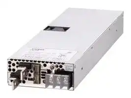
FETA2500BA-48
AC/DC Enclosed Power Supply (PSU), ITE, 1 Outputs, 2.496 kW, 48 V, 52 A
⚠️ Reference pricing provided. In case of supply shortages, we will connect you with our trusted procurement partners to ensure your project's continuity.
- Manufacturer: COSEL
- Product type: AC / DC Enclosed Power Supplies
- SVHC: Lead (04-Feb-2026)
- Product Range: FET Series
- No. of Outputs: 1Outputs
- Output Power Max: 2.496kW
- Current, Output 4: -
- Input Voltage VAC: 170V AC to 264V AC
- Power Supply Output Type: Fixed
- Output Current - Output 1: 52A
- Output Current - Output 2: -
- Output Current - Output 3: -
- Output Voltage - Output 1: 48V
- Output Voltage - Output 2: -
- Output Voltage - Output 3: -
- Output Voltage - Output 4: -
- Power Supply Applications: ITE
| Delivery and price | |
|---|---|
| Units per pack | 1 |
| Price | 465.68 € |
| Current stock | 10+ |
| Lead time | 30 days |
Datasheet

**AC-DC Power Supplies Enclosed Type** ~~|~~ E ~~ss~~ 1U ~~ii~~ Power We Safety EMI Rs 0) Inrush OCP sh ted OVP Remote E ~~S~~ Parallel High output Factor Approvals current ON/OFF Operation voltage Correction limiting

## **FETA-series**

## **Feature**

**3-year warranty** (Refer to Instruction Manual)

High power density

Low profile (Meets 1U height.) High output voltage (FETA3000BC-250, FETA7000T-144, FETA7000ST-144) High efficiency High-speed response (FETA3000BC) Harmonic attenuator

( FETA2500BA, 3000BA, 3000BC, 7000ST : Complies with IEC61000-3-2 Class A FETA7000T : Complies with IEC61000-3-12) Complies with SEMI F47 Parallel Operation / Parallel Redundancy Operation Alarm signals, Remote ON / OFF and other functions

## **Safety agency approvals**

UL62368-1, C-UL(CSA62368-1), EN62368-1

## **EMI**

## **CE marking**

Low voltage Directive RoHS Directive

## **UKCA marking**

Electrical Equipment Safety Regulations RoHS Regulations

**EMS Compliance** : EN61204-3, EN61000-6-2

EN61000-4-2 EN61000-4-3 EN61000-4-4 EN61000-4-5 EN61000-4-6 EN61000-4-8 EN61000-4-11

Complies with FCC Part 15-A, CISPR32-A, EN55032-A, VCCI-A

( FETA7000ST : Complies with FCC Part 15-A, CISPR32-A, EN55032-A, VCCI-A by connecting an external EMI/EMC filter)

**FETA-1**

www.cosel.co.jp/en/

July 13, 2023

**AC-DC Power Supplies Enclosed Type FETA2500BA** ~~|~~

**Ordering information**

## **FET A 2500 B A -** OO **-** O

1 2 3 4 5 6 7

**==> picture [2 x 3] intentionally omitted <==**

**----- Start of picture text -----**<br>
R<br>**----- End of picture text -----**<br>


**Example recommended EMI/EMC filter NAC-20-472**

- 1Series name

- 2Single output

- 3Output wattage 4200/230V input

- 5Version

- 6Output voltage

- 7Optional

F2: Reverse air exhaust R:  with Remote ON/OFF High voltage pulse noise type : NAP seriesLow leakage current type : NAM series Positive logic control *A higher current rating EMI/EMC filter may be recommended in view of the other devices that could be connected in parallel with the power supply.

*Make sure necessary tests will be carried out on your end equipment with the power supply installed in accordance with any required EMC/EMI regulations.

||**MODEL**<br>~~a~~|**MODEL**<br>~~a~~|**FETA2500BA-36**|**FETA2500BA-48**|
|---|---|---|---|---|
|**INPUT**|**VOLTAGE[V]**<br>~~ee~~||AC170- 264 1f (Outputderatingisrequired at AC170V - 180V.  Refer to“Derating”)<br>~~ee~~||
||**CURRENT[A]**<br>~~ee~~|**ACIN 200V**<br>~~ee~~|11.3typ<br>~~ee~~|13.8typ|
||**FREQUENCY[Hz]**||50 / 60 (47 -63)||
||**EFFICIENCY[%]**<br>~~|~~|**ACIN 230V**|80typ (Io=10%)<br>~~PO~~|83typ (Io=10%)|
||||87typ (Io=20%)<br>~~PO~~|89typ (Io=20%)|
||||91typ (Io=50%)<br>~~PO~~<br>~~ot~~|92.5typ (Io=50%)|
||||90typ (Io=100%)<br>~~PO~~<br>~~ot~~|91.5typ (Io=100%)|
||**POWER FACTOR**<br>~~ee~~|**ACIN 230V**<br>~~ee~~|0.98typ (Io=100%)||
||**INRUSH CURRENT[A]**<br>~~ee~~|**ACIN 200V**<br>*2 <br>~~ee~~|20max/ 60max(Primaryinrushcurrent/Secondaryinrushcurrent) (Morethan 10 sec. tore-start)||
||**LEAKAGE CURRENT[mA]**||0.85max(ACIN 240V60Hz,Io=100%,AccordingtoIEC62368-1)||
|**OUTPUT**<br>~~ee~~<br>~~————~~<br>~~fF~~|**VOLTAGE[V]**<br>~~a~~<br>~~le~~<br>~~ee~~||36<br>~~ee~~|48|
||**CURRENT[A]**<br>~~le~~|**ACIN 170V-180V**<br>~~ee~~|Outputderatingisrequired at ACIN 180Vor less (refer to“Derating”)<br>~~ee~~||
|||**ACIN 180V-264V**<br>~~ee~~|55<br>~~ee~~|52|
||**LINE REGULATION[mV]**<br>~~le~~<br>~~ee~~<br>~~ee~~||144max<br>~~ee~~<br>~~ee~~|192max|
||**LOAD REGULATION[mV]**<br>~~ee~~<br>~~ee~~||360max<br>~~ee~~<br>~~ee~~|480max<br>~~ee~~|
||**RIPPLE[mVp-p]**<br>~~ee~~<br>~~ee~~|**0 to +50**C<br>*3|300max<br>~~ee~~|360max<br>~~ee~~|
|||**-10 to 0**C<br>*3 <br>~~_—,~~|360max<br>~~ee~~<br>~~_—,~~|480max<br>~~ee~~|
||**RIPPLE NOISE[mVp-p]**<br>~~ee~~<br>~~ee~~|**0 to +50**C<br>*3 <br>~~_—,~~|360max<br>~~ee~~<br>~~_—,~~|480max<br>~~ee~~|
|||**-10 to 0**C<br>*3 <br>~~_—,~~|480max<br>~~_—,~~|600max|
||**TEMPERATURE REGULATION[mV]**<br>~~ee~~<br>~~__~~<br>~~————~~|**0 to +50**C<br>~~_—,~~<br>~~__~~|360max<br>~~_—,~~<br>~~__~~|480max|
|||**-10 to +50**C<br>~~__~~|440max<br>~~__~~|600max|
||**DRIFT[mV]**<br>*4<br>~~————~~||144max|192max|
||**START-UP TIME[s]**<br>~~————~~<br>~~——~~||1.7max(ACIN 200V,Io=100%)<br>~~——————~~||
||**HOLD-UP TIME[ms]**<br>~~————~~<br>~~——~~|**ACIN 200V**<br>~~——~~|10typ (Io=100%)<br>~~——————~~||
||||20typ (Io=50%)<br>~~——————~~||
||**OUTPUT VOLTAGE ADJUSTMENT RANGE[V]** *5<br>~~——~~||28.80-39.60<br>~~——————~~|38.40-52.80 *6|
||**OUTPUT VOLTAGE SETTING[V]**<br>~~—— ~~<br>~~Qe~~<br>~~fF~~||36.00-37.44<br> ~~——————~~<br>~~Qe~~|48.00- 49.92|
|**PROTECTION**<br>**CIRCUIT AND**<br>**OTHERS**<br>~~fFee~~<br>~~——~~<br>~~fC~~|**OVERCURRENT PROTECTION**<br>~~fFee~~||Activate over 105% - 120% of rated current and recovers automatically.<br>(Output voltage shuts down when the output voltage continuously drops dueto overcurrentprotection.) *7||
||**OVERVOLTAGE PROTECTION[V]**<br>*7<br>~~fFee~~<br>~~——~~||42.00- 45.00|56.00-60.00|
||**DC_OK LAMP**<br>~~ee~~<br>~~——~~||LED(Green)||
||**ALARM LAMP**<br>~~——PO~~<br>~~fC~~<br>~~—“‘;‘“C:C*S*sSCSCSC*dzr~~||LED(Amber)||
||**REMOTEON/OFF**<br>~~fC~~<br>~~—“‘;‘“C:C*S*sSCSCSC*dzr~~||Provided||
|**ISOLATION**<br>~~fC~~<br>~~——~~|**INPUT-OUTPUT**-**AUX**-**RC**-**WRN**-**PG**<br>~~fC~~<br>~~—“‘;‘“C:C*S*sSCSCSC*dzr~~<br>~~Po~~||AC3,000V 1minute, Cutoffcurrent = 25mA,DC500V50MWmin(At room temperature)||
||**INPUT-FG**<br>~~Po~~<br>~~——~~||AC2,000V 1minute, Cutoffcurrent = 25mA,DC500V50MWmin(At room temperature)||
||**OUTPUT**-**AUX**-**RC**-**WRN**-**PG-FG**<br>~~——~~||AC500V 1minute, Cutoffcurrent = 100mA,DC500V50MWmin(At room temperature)||
||**OUTPUT-AUX**-**RC**-**WRN**-**PG**<br>~~——Po~~||AC100V 1minute, Cutoffcurrent = 100mA,DC100V50MWmin(At room temperature)||
|**ENVIRONMENT**<br>~~——~~<br>~~|~~|**OPERATING TEMP.,HUMID.AND ALTITUDE**<br>~~Po~~<br>~~——~~||-10to+70C (Refer to“Derating”),20-90%RH(Noncondensing), 3,000m(10,000feet)max||
||**STORAGE TEMP.,HUMID.AND ALTITUDE**<br>~~——~~||-20to+85C,20-90%RH(Noncondensing), 9,000m(30,000feet)max||
||**VIBRATION**<br>~~——Po~~<br>~~|~~||10-55Hz,19.6m/s2 (2G), 3minutes period, 60minutes eachalongX,YandZaxis||
||**IMPACT**<br>~~|~~<br>C—“(ti‘“C:sSCSCSCSCidr||196.1m/s2 (20G),11ms, once eachalongX,YandZaxis||
|**SAFETY AND**<br>**NOISE REGULATIONS**<br>~~|~~<br>~~——~~<br>~~_~~|**AGENCY APPROVALS**<br>~~|~~<br>~~Po~~<br>~~——~~||UL62368-1, C-UL(CSA62368-1),EN62368-1||
||**CONDUCTED NOISE**<br>~~——~~||Complieswith FCCPart 15-A, CISPR32-A,EN55032-A,VCCI-A||
||**HARMONIC ATTENUATOR**<br>~~——~~<br>~~Po~~<br>~~_~~||Complieswith IEC61000-3-2ClassA*8||
|**OTHERS**<br>~~_~~|**CASE SIZE/WEIGHT**<br>*9<br>~~_~~||102X41X340mm[4.02X1.61X13.39 inches] (WXHXD)/ 2.3kgmax||
||**COOLING METHOD**<br>~~_~~||Forced cooling (internal fan)||


- *1 AUX output power is not included.

- *2 The current of input surge to a built-in noise filter (0.2ms or less) is excluded.

- *3 Measured by 500MHz oscilloscope.

   - Ripple and ripple noise is measured on measuring board with capacitor of 22mF within 150mm from the output terminal.

- *4 Drift is the change in DC output for an eight hour period after a half-hour warm-up at 25C, with the input voltage held constant at the rated input/output.

   - *7 Output voltage recovers from protection by shutting down the input voltage and waiting more than 10 seconds then turning on AC input again, or turning off the output voltage by remote control.

   - *8 Please contact us about another class.

   - *9 Case size contains neither the terminal blocks, connector and screw.

      - To meet the specifications, do not operate over-loaded condition.

   -

   - A sound may occur from power supply at peak loading.

- *5 Can't be used above the rated output current and the rated output power.

- *6 When the output voltage is adjusted to higher than 49.92V and the load factor is over 70% of the rated current, if the load current changes quickly (< 200msec), the output voltage drops approximately 5V below the setting voltage.

**FETA-2**

www.cosel.co.jp/en/

July 13, 2023

**FETA2500BA**

## **Block diagram**

**==> picture [478 x 281] intentionally omitted <==**

**----- Start of picture text -----**<br>
FUSE 250V 30A<br>AC IN L NOISE INRUSH RECTIFIER<br>170  -  264V N CURRENT INVERTER AND<br>FILTER LIMIT FILTER<br>FG<br>VOLTAGE CURRENT<br>SENSING SENSING<br>VOLTAGE<br>CONTROL<br>SENSING<br>RECTIFIER<br>INVERTER AND DC OUT<br>FILTER<br>CURRENT<br>SENSING<br>SYNCHRONIZING CURRENT THERMAL THERMAL<br>SIGNAL SENSING PROTECTION PROTECTION<br>MASTER VB (VOLTAGE BALANCE)<br>SLAVE<br>CONTROL CB (CURRENT BALANCE)<br>OVER VOLTAGE<br>PROTECTION TRM (ADJUSTMENT OF<br> OUTPUT VOLTAGE)<br>CONTROL CONTROL<br>RC (REMOTE ON / OFF)<br>CONTROL ALARM PG (POWER GOOD)<br>REGULATORINTERNAL FAN WARNINGSIGNAL WRN (WARNING)<br>AUX  ( 12V 0.15A )<br>**----- End of picture text -----**<br>


## **External view**

**==> picture [473 x 348] intentionally omitted <==**

**----- Start of picture text -----**<br>
7.5<br>[0.30]<br>2-M4<br>15 288±0.5<br>[0.59] [11.34] Mounting Hole<br>LED(Alarm)Amber (35) 340<br>[1.38] (17) [13.39]<br>LED(DC OK)Green Outputterminal(-) [0.67] (12.5)[0.49] Name plate<br>Output<br>terminal(+)<br>Output  voltage<br>adjustable<br>potentiometer<br>CN1 2-M4<br>CN2<br>FG(   )<br>AC(N)<br>AC(L)<br>10.7 M4 Name plate 19max Input terminal cover 2-M4<br>[0.42] [0.75]<br>16.6 2-f7 Mounting Hole<br>[0.65]<br>[0.28]<br>AIR FLOW<br>47 235±0.5<br>[1.85] [9.25]<br>3-M4<br>Mounting Hole<br>(Bottom)<br> PCB material / thickness : FR-4 / 1.6mm [0.06]<br>-m maxm max<br>-m maxm max [0.98]25 [10.43]265±0.5<br>13 [0.51] 6 [0.24]<br>(12) [0.47] 20 [0.79]<br>(16) [0.63]<br>13 [0.51]6 [0.24]<br>(13) [0.51]3 [0.12]<br>(13) [0.51]<br>3<br>[0.12] 102 [4.02]<br>75.5 [2.97]<br>44.5 [1.75] 11 [0.43] 68.5 [2.70] 9[0.35] f9.8)( [0.39]<br>(10.5) [0.41]<br>41 [1.61]<br>20 [0.79]<br>22 [0.87]<br>±0.5<br>30 [1.18]<br>±0.5<br>60 [2.36]<br>**----- End of picture text -----**<br>


- Tolerance ±1 [±0.04]

- Weight : 2.3kg max

- PCB material / thickness : FR-4 / 1.6mm [0.06]

- Chassis material : Stainless steel

- Dimensions in mm, [  ]=inches

- Maunting torque : 1.2N-m maxm max

- Screw tightening torque : 1.6N-m maxm max

- Please connect safety ground to FG terminal on the unit.

**FETA-3**

www.cosel.co.jp/en/

July 13, 2023

**AC-DC Power Supplies Enclosed Type FETA3000BA** ~~|~~

**Ordering information**

## **FET A 3000 B A -** OO **-** O

1 2 3 4 5 6 7

**==> picture [2 x 3] intentionally omitted <==**

**----- Start of picture text -----**<br>
R<br>**----- End of picture text -----**<br>


**Example recommended EMI/EMC filter NAC-20-472**

1Series name 2Single output

3Output wattage

- 4200/230V input

- 5Version

High voltage pulse noise type : NAP series Low leakage current type : NAM series *A higher current rating EMI/EMC filter may be recommended in view of the other devices that could be connected in parallel with the power supply.

6Output voltage 7Optional R:  with Remote ON/OFF Positive logic control

*Make sure necessary tests will be carried out on your end equipment with the power supply installed in accordance with any required EMC/EMI regulations.

|~~-————~~|**MODEL**<br>~~PO~~<br>~~-————~~<br>~~"J~~|**MODEL**<br>~~PO~~<br>~~-————~~<br>~~"J~~|**FETA3000BA-48**<br>~~"J~~|
|---|---|---|---|
|**INPUT**<br>~~-————~~|**VOLTAGE[V]**<br>~~-————~~<br>~~"J~~||AC170- 264 1f (Outputderatingisrequired at AC170V - 180V.  Refer to“Derating”)<br>~~"J~~|
||**CURRENT[A]**<br>~~-————~~|**ACIN 200V**<br>~~"J~~|16.6typ<br>~~"J~~|
||**FREQUENCY[Hz]**<br>~~-————~~<br>~~"J~~||50 / 60 (47 -63)<br>~~"J~~|
||**EFFICIENCY[%]**<br>~~|~~|**ACIN 230V**|82typ (Io=10%)|
||||90typ (Io=20%)|
||||93typ (Io=50%)|
||||91.5typ (Io=100%)|
||**POWER FACTOR**<br>~~|~~|**ACIN 230V**|0.98typ (Io=100%)|
||**INRUSH CURRENT[A]**<br>~~ee~~|**ACIN 200V**<br>*2 <br>~~ee~~|20max/ 80max(Primaryinrushcurrent/Secondaryinrushcurrent) (Morethan 10 sec. tore-start)|
||**LEAKAGE CURRENT[mA]**||0.85max(ACIN 240V60Hz,Io=100%,AccordingtoIEC62368-1)|
|**OUTPUT**<br>~~fF~~|**VOLTAGE[V]**<br>~~Po~~<br>~~eeee~~||48<br>~~ee~~|
||**CURRENT[A]**<br>~~ee~~|**ACIN 170V-180V**<br>~~ee~~|Outputderatingisrequired at ACIN 180Vor less (refer to“Derating”)<br>~~ee~~|
|||**ACIN 180V-264V**<br>~~ee~~|62<br>~~ee~~|
||**LINE REGULATION[mV]**<br>~~ee ee~~<br>~~[J~~||192max<br>~~ee~~|
||**LOAD REGULATION[mV]**<br>~~[J~~<br>~~eleee~~||480max<br>~~eee~~|
||**RIPPLE[mVp-p]**<br>~~el~~<br>~~el~~|**0 to +50**C<br>*3 <br>~~eee~~|360max(Vo=15-52.8[V]) *4<br>~~eee~~|
|||**-10 to 0**C<br>*3 <br>~~eee~~<br>~~eee~~|480max(Vo=15-52.8[V]) *4<br>~~eee~~|
||**RIPPLE NOISE[mVp-p]**<br>~~el ~~<br>~~el~~<br>~~el~~|**0 to +50**C<br>*3 <br> ~~eee~~<br>~~eee~~|600max(Vo=15-52.8[V]) *4<br>~~eee~~|
|||**-10 to 0**C<br>*3 <br>~~eee~~<br>~~eee~~|720max(Vo=15-52.8[V]) *4|
||**TEMPERATURE REGULATION[mV]**<br>~~el ~~<br>~~el~~|**0 to +50**C<br> ~~eee~~<br>~~eee~~|480max|
|||**-10 to +50**C<br>~~eee~~|600max|
||**DRIFT[mV]**<br>*4<br>~~el eee~~<br>~~[J~~||192max|
||**START-UP TIME[s]**<br>*5<br>~~[J~~<br>~~ee~~||1.7max(ACIN 200V,Io=100%)|
||**HOLD-UP TIME[ms]**<br>~~ee~~|**ACIN 200V**<br>~~ee~~<br>~~ee~~|10typ (Io=100%)|
||||20typ (Io=50%)|
||**OUTPUT VOLTAGE ADJUSTMENT RANGE[V]** *6<br>~~ee~~||38.40-52.80|
||**OUTPUT VOLTAGE SETTING[V]**<br>~~Po~~<br>~~fF~~||48.00- 49.00|
|**PROTECTION**<br>**CIRCUIT AND**<br>**OTHERS**<br>~~fF~~<br>~~——~~<br>~~fC~~|**OVERCURRENT PROTECTION**<br>~~fF~~||Activate over 105% - 120% of rated current and recovers automatically.<br>(Output voltage shuts down when the output voltage continuously drops dueto overcurrentprotection.) *7|
||**OVERVOLTAGE PROTECTION[V]**<br>*7<br>~~fF——~~<br>~~——~~||56.00-60.00|
||**DC_OK LAMP**<br>~~——~~||LED(Green)|
||**ALARM LAMP**<br>~~——PO~~<br>~~fC~~<br>~~—“‘;‘“C:C*S*sSCSCSC*dzr~~||LED(Amber)|
||**REMOTEON/OFF**<br>~~fC~~<br>~~—“‘;‘“C:C*S*sSCSCSC*dzr~~||Provided|
|**ISOLATION**<br>~~fC~~<br>~~——~~|**INPUT-OUTPUT**-**AUX**-**RC**-**WRN**-**PG**<br>~~fC~~<br>~~—“‘;‘“C:C*S*sSCSCSC*dzr~~<br>~~Po~~||AC3,000V 1minute, Cutoffcurrent = 25mA,DC500V50MWmin(At room temperature)|
||**INPUT-FG**<br>~~Po~~<br>~~——~~||AC2,000V 1minute, Cutoffcurrent = 25mA,DC500V50MWmin(At room temperature)|
||**OUTPUT**-**AUX**-**RC**-**WRN**-**PG-FG**<br>~~——~~||AC500V 1minute, Cutoffcurrent = 100mA,DC500V50MWmin(At room temperature)|
||**OUTPUT-AUX**-**RC**-**WRN**-**PG**<br>~~——Po~~||AC100V 1minute, Cutoffcurrent = 100mA,DC100V50MWmin(At room temperature)|
|**ENVIRONMENT**<br>~~——~~<br>~~|~~|**OPERATING TEMP.,HUMID.AND ALTITUDE**<br>~~Po~~<br>~~——~~||-10to+70C (Refer to“Derating”),20-90%RH(Noncondensing), 3,000m(10,000feet)max|
||**STORAGE TEMP.,HUMID.AND ALTITUDE**<br>~~——~~||-20to+85C,20-90%RH(Noncondensing), 9,000m(30,000feet)max|
||**VIBRATION**<br>~~——Po~~<br>~~|~~||10-55Hz,19.6m/s2 (2G), 3minutes period, 60minutes eachalongX,YandZaxis|
||**IMPACT**<br>~~|~~<br>C—“(ti‘“C:sSCSCSCSCidr||196.1m/s2 (20G),11ms, once eachalongX,YandZaxis|
|**SAFETY AND**<br>**NOISE REGULATIONS**<br>~~|~~<br>~~——~~<br>~~_~~|**AGENCY APPROVALS**<br>~~|~~<br>~~Po~~<br>~~——~~||UL62368-1, C-UL(CSA62368-1),EN62368-1|
||**CONDUCTED NOISE**<br>~~——~~||Complieswith FCCPart 15-A, CISPR32-A,EN55032-A,VCCI-A|
||**HARMONIC ATTENUATOR**<br>~~——~~<br>~~Po~~<br>~~_~~||Complieswith IEC61000-3-2ClassA*8|
|**OTHERS**<br>~~_~~|**CASE SIZE/WEIGHT**<br>*9<br>~~_~~||102X41X340mm[4.02X1.61X13.39 inches] (WXHXD)/ 2.3kgmax|
||**COOLING METHOD**<br>~~_~~||Forced cooling (internal fan)|


- *1 AUX output power is not included.

- *2 The current of input surge to a built-in noise filter (0.2ms or less) is excluded.

- *3 Measured by 500MHz oscilloscope.

   - Ripple and ripple noise is measured on measuring board with capacitor of 22mF within 150mm from the output terminal.

- *4 The output voltage should not be adjusted to 15V or less because the ripple and ripple noise would be out of specs and the unit would make the audible noise.

more than 10 seconds then turning on AC input again, or turning off the output voltage by remote control.

   - *8 Please contact us about another class.

   - *9 Case size contains neither the terminal blocks, connector and screw.

      - To meet the specifications, do not operate over-loaded condition.

   -

   - A sound may occur from power supply at peak loading.

- *5 Drift is the change in DC output for an eight hour period after a half-hour warm-up at 25C, with the input voltage held constant at the rated input/output.

- *6 Can't be used above the rated output current and the rated output power.

- *7 Output voltage recovers from protection by shutting down the input voltage and waiting

**FETA-4**

www.cosel.co.jp/en/

July 13, 2023

**FETA3000BA**

## **Block diagram**

**==> picture [478 x 281] intentionally omitted <==**

**----- Start of picture text -----**<br>
FUSE 250V 30A<br>AC IN L NOISE INRUSH RECTIFIER<br>170  -  264V N CURRENT INVERTER AND<br>FILTER LIMIT FILTER<br>FG<br>VOLTAGE CURRENT<br>SENSING SENSING<br>VOLTAGE<br>CONTROL<br>SENSING<br>RECTIFIER<br>INVERTER AND DC OUT<br>FILTER<br>CURRENT<br>SENSING<br>SYNCHRONIZING CURRENT THERMAL THERMAL<br>SIGNAL SENSING PROTECTION PROTECTION<br>MASTER VB (VOLTAGE BALANCE)<br>SLAVE<br>CONTROL CB (CURRENT BALANCE)<br>OVER VOLTAGE<br>PROTECTION TRM (ADJUSTMENT OF<br> OUTPUT VOLTAGE)<br>CONTROL CONTROL<br>RC (REMOTE ON / OFF)<br>CONTROL ALARM PG (POWER GOOD)<br>REGULATORINTERNAL FAN WARNINGSIGNAL WRN (WARNING)<br>AUX  ( 12V 0.15A )<br>**----- End of picture text -----**<br>


## **External view**

**==> picture [473 x 348] intentionally omitted <==**

**----- Start of picture text -----**<br>
7.5<br>[0.30]<br>2-M4<br>15 288±0.5<br>[0.59] [11.34] Mounting Hole<br>LED(Alarm)Amber (35) 340<br>[1.38] (17) [13.39]<br>LED(DC OK)Green Outputterminal(-) [0.67] (12.5)[0.49] Name plate<br>Output<br>terminal(+)<br>Output  voltage<br>adjustable<br>potentiometer<br>CN1 2-M4<br>CN2<br>FG(   )<br>AC(N)<br>AC(L)<br>10.7 M4 Name plate 19max Input terminal cover 2-M4<br>[0.42] [0.75]<br>16.6 2-f7 Mounting Hole<br>[0.65]<br>[0.28]<br>AIR FLOW<br>47 235±0.5<br>[1.85] [9.25]<br>3-M4<br>Mounting Hole<br>(Bottom)<br> PCB material / thickness : FR-4 / 1.6mm [0.06]<br>-m maxm max<br>-m maxm max [0.98]25 [10.43]265±0.5<br>13 [0.51] 6 [0.24]<br>(12) [0.47] 20 [0.79]<br>(16) [0.63]<br>13 [0.51]6 [0.24]<br>(13) [0.51]3 [0.12]<br>(13) [0.51]<br>3<br>[0.12] 102 [4.02]<br>75.5 [2.97]<br>44.5 [1.75] 11 [0.43] 68.5 [2.70] 9[0.35] f9.8)( [0.39]<br>(10.5) [0.41]<br>41 [1.61]<br>20 [0.79]<br>22 [0.87]<br>±0.5<br>30 [1.18]<br>±0.5<br>60 [2.36]<br>**----- End of picture text -----**<br>


- Tolerance ±1 [±0.04]

- Weight : 2.3kg max

- PCB material / thickness : FR-4 / 1.6mm [0.06]

- Chassis material : Stainless steel

- Dimensions in mm, [  ]=inches

- Maunting torque : 1.2N-m maxm max

- Screw tightening torque : 1.6N-m maxm max

- Please connect safety ground to FG terminal on the unit.

**FETA-5**

www.cosel.co.jp/en/

July 13, 2023

**Ordering information**

## **AC-DC Power Supplies Enclosed Type FETA3000BC** ~~Yd~~

**==> picture [2 x 3] intentionally omitted <==**

**----- Start of picture text -----**<br>
R<br>**----- End of picture text -----**<br>


## **FET A 3000 B C -** OO **-** O

1 2 3 4 5 6 7

- 1Series name 2Single output

**Example recommended EMI/EMC filter NAC-20-472**

- 3Output wattage 4200/230V input

- 5Version

High voltage pulse noise type : NAP series Low leakage current type : NAM series *A higher current rating EMI/EMC filter may be recommended in view of the other devices that could be connected in parallel with the power supply.

- 6Output voltage 7Optional R:  with Remote ON/OFF Positive logic control

*Make sure necessary tests will be carried out on your end equipment with the power supply installed in accordance with any required EMC/EMI regulations.

||**MODEL**<br>~~Po~~|**MODEL**<br>~~Po~~|**FETA3000BC-250**|
|---|---|---|---|
|**INPUT**|**VOLTAGE[V]**<br>~~—_—~~||AC170- 264 1f (Outputderatingisrequired at AC170V - 180V.  Refer to“Derating”)|
||**CURRENT[A]**<br>~~—_—~~|**ACIN 200V**<br>~~—_—~~|16.8typ|
||**FREQUENCY[Hz]**<br>~~—_—~~||50 / 60 (47 -63)|
||**EFFICIENCY[%]**<br>~~ee~~|**ACIN 230V**<br>~~ee~~<br>~~ee~~|93typ (Io=50%)|
||||91.5typ (Io=100%)<br>~~ee~~|
||**POWER FACTOR**<br>~~ee~~|**ACIN 230V**<br>~~ee~~<br>~~ee~~|0.98typ (Io=100%)<br>~~ee~~|
||**INRUSH CURRENT[A]**<br>~~ee~~<br>~~————~~|**ACIN 200V**<br>*1 <br>~~ee~~<br>~~ee~~<br>~~————~~|20max/ 80max(Primaryinrushcurrent/Secondaryinrushcurrent) (Morethan 10 sec. tore-start)<br>~~ee~~|
||**LEAKAGE CURRENT[mA]**<br>~~————~~||0.85max(ACIN 240V60Hz,Io=100%,AccordingtoIEC62368-1)|
|**OUTPUT**|**VOLTAGE[V]**<br>~~Po~~||250|
||**CURRENT[A]**<br>~~——~~|**ACIN 170V-180V**<br>~~——~~|Outputderatingisrequired at ACIN 180Vor less (refer to“Derating”)|
|||**ACIN 180V-264V**<br>~~——~~|12|
||**LINE REGULATION[V]**||1.0max|
||**LOAD REGULATION[V]**<br>~~Po~~||2.5max|
||**RIPPLE[Vp-p]**<br>~~—~~|**0 to +40**C<br>*2 <br>~~—~~|12max|
|||**-10 to 0**C<br>*2 <br>~~—~~|13.2max|
||**RIPPLE NOISE[Vp-p]**<br>~~—~~|**0 to +40**C<br>*2 <br>~~—~~|12max|
|||**-10 to 0**C<br>*2 <br>~~—~~|13.2max|
||**TEMPERATURE REGULATION[V]**<br>~~—__—~~|**0 to +40**C<br>~~—__—~~|2.5max|
|||**-10 to 40**C<br>~~—__—~~|3.2max|
||**DRIFT[V]**<br>*3 <br>~~—__—~~||1.0max|
||**START-UP TIME[s]**<br>~~Po~~||1.0max(ACIN 200V,Io=100%)|
||**HOLD-UP TIME[ms]**<br>~~——_t~~|**ACIN 200V**<br>~~——_t~~|10typ (Io=100%)|
||||20typ (Io=50%)|
||**OUTPUT VOLTAGE ADJUSTMENT RANGE[V]** *4 <br>~~——_t~~||180-350|
||**OUTPUT VOLTAGE SETTING[V]**<br>~~Po~~||250- 253|
|**PROTECTION**<br>**CIRCUIT AND**<br>**OTHERS**|**OVERCURRENT PROTECTION**<br>~~—_~~||Activate over 105% - 120% of rated current and recovers automatically.<br>(Output voltage shuts down when the output voltage continuously drops dueto overcurrentprotection.) *5|
||**OVERVOLTAGE PROTECTION[V]**<br>*5 <br>~~Po~~||400- 450 (Active over 160%-180% of ratedvoltage.) *6|
||**DC_OK LAMP**<br>~~Po~~||LED(Green)|
||**ALARM LAMP**<br>~~Po~~||LED(Amber)|
||**REMOTEON/OFF**<br>~~PT~~||Provided|
|**ISOLATION**|**INPUT-OUTPUT**-**RC**-**WRN**-**PG**<br>~~Po~~||AC3,000V 1minute, Cutoffcurrent = 25mA,DC500V50MΩmin(At room temperature)|
||**INPUT-FG**<br>~~Po~~||AC2,000V 1minute, Cutoffcurrent = 25mA,DC500V50MΩmin(At room temperature)|
||**OUTPUT-FG**<br>~~Po~~||AC2,000V 1minute, Cutoffcurrent = 25mA,DC500V50MΩmin(At room temperature)|
||**RC**-**WRN**-**PG-FG**<br>~~Po~~||AC500V 1minute, Cutoffcurrent = 100mA,DC500V50MΩmin(At room temperature)|
||**OUTPUT-RC**-**WRN**-**PG**<br>~~Po~~||AC3,000V 1minute, Cutoffcurrent = 25mA,DC500V50MΩmin(At room temperature)|
|**ENVIRONMENT**|**OPERATING TEMP.,HUMID.AND ALTITUDE**<br>~~Po~~||-10to+70C (Refer to“Derating”),20-90%RH(Noncondensing), 3,000m(10,000feet)max|
||**STORAGE TEMP.,HUMID.AND ALTITUDE**<br>~~Po~~||-20to+85C,20-90%RH(Noncondensing), 9,000m(30,000feet)max|
||**VIBRATION**<br>~~Po~~||10-55Hz,19.6m/s2 (2G), 3minutes period, 60minutes eachalongX,YandZaxis|
||**IMPACT**<br>~~Po~~||196.1m/s2 (20G),11ms, once eachalongX,YandZaxis|
|**SAFETY AND**<br>**NOISE REGULATIONS**|**AGENCY APPROVALS**<br>~~Po~~||UL62368-1, C-UL(CSA62368-1),EN62368-1|
||**CONDUCTED NOISE**<br>~~Po~~||Complieswith FCCPart 15-A, CISPR32-A,EN55032-A,VCCI-A|
||**HARMONIC ATTENUATOR**<br>~~PO~~||Complieswith IEC61000-3-2ClassA*7|
|**OTHERS**|**CASE SIZE/WEIGHT**<br>*8 <br>~~Po~~||102X41X340mm[4.02X1.61X13.39 inches] (WXHXD)/ 2.3kgmax|
||**COOLING METHOD**<br>~~Po~~||Forced cooling (internal fan)|


- *1 The current of input surge to a built-in noise filter (0.2ms or less) is excluded.

- *2 Measured by 500MHz oscilloscope.

   - Ripple and ripple noise is measured on measuring board with capacitor of 2.2μF within 150mm from the output terminal.

- *3 Drift is the change in DC output for an eight hour period after a half-hour warm-up at 25C, with the input voltage held constant at the rated input/output.

   - *6 Since the voltage adjustment range is wide, the operating voltage of the overvoltage protection is set high.

   - *7 Please contact us about another class.

   - *8 Case size contains neither the terminal blocks, connector and screw.

   - To meet the specifications, do not operate over-loaded condition.

   - A sound may occur from power supply at peak loading.

- *4 Can't be used above the rated output current and the rated output power.

- *5 Output voltage recovers from protection by shutting down the input voltage and waiting more than 10 seconds then turning on AC input again, or turning off the output voltage by remote control.

**FETA-6**

www.cosel.co.jp/en/

July 13, 2023

**FETA3000BC**

## **Block diagram**

**==> picture [484 x 260] intentionally omitted <==**

**----- Start of picture text -----**<br>
FUSE 250V 30A<br>AC IN L NOISE INRUSH RECTIFIER<br>170 - 264V N CURRENT INVERTER AND<br>FILTER LIMIT FILTER<br>FG<br>VOLTAGE CURRENT<br>SENSING SENSING<br>VOLTAGE<br>CONTROL<br>SENSING<br>RECTIFIER<br>INVERTER AND DC OUT<br>FILTER<br>CURRENT<br>SENSING<br>SYNCHRONIZING CURRENT THERMAL THERMAL<br>SIGNAL SENSING PROTECTION PROTECTION<br>MASTER VB (VOLTAGE BALANCE)<br>SLAVE<br>CONTROL CB (CURRENT BALANCE)<br>OVER VOLTAGE<br>PROTECTION TRM (ADJUSTMENT OF<br> OUTPUT VOLTAGE)<br>CONTROL CONTROL 制御<br>RC (REMOTE ON / OFF)<br>CONTROL ALARM PG (POWER GOOD)<br>REGULATORINTERNAL FAN WARNINGSIGNAL WRN (WARNING)<br>**----- End of picture text -----**<br>


## **External view**

**==> picture [477 x 345] intentionally omitted <==**

**----- Start of picture text -----**<br>
7.5<br>[0.30]<br>LED(Alarm)Amber (35)[1.38] [0.59]15 288[11.34]340±0.5 Mounting Hole2-M4<br>LED(DC OK)Green Outputterminal(-) (17)[0.67] (12.5)[0.49] Name plate [13.39]<br>Outputterminal(+)<br>Output  voltage<br>adjustable<br>potentiometer<br>CN1 2-M4<br>CN2<br>CN3<br>FG ( )<br>AC(N)<br>AC(L)<br>[0.42]10.7 M4 Name plate 19max Input terminal cover 2-M4<br>16.6 [0.75] Mounting Hole<br>[0.65] 2- f 7<br>[0.28]<br>AIR FLOW<br>47 235±0.5<br>[1.85] [9.25]<br>3-M4<br>Mounting Hole<br>(Bottom)<br> PCB material / thickness : FR-4 / 1.6mm [0.06]<br> Chassis material : Stainless steel<br> Dimensions in mm, [  ]=inches<br>-m maxm max<br> Screw tightening torque : 1.6N-m max-m maxm max [0.98]25 265[10.43]±0.5<br>13 [0.51] 6 [0.24]<br>)(12 [0.47] 20 [0.79]<br>(16) [0.63]<br>13 [0.51] 6 [0.24]<br>)(13 [0.51]3 [0.12]<br>)(13 [0.51]<br>3<br>[0.12]<br>102 [4.02]<br>44.5 [1.75] 11 [0.43] 75.5 [2.97] 68.5 [2.70] 9[0.35] f 9.8)(0.39][<br>)(10.5 [0.41]<br>41 [1.61]<br>20 [0.79]<br>22 [0.87]<br>30±0.5 [1.18]<br>60±0.5 [2.36]<br>**----- End of picture text -----**<br>


- Tolerance ±1 [±0.04]

- Weight : 2.3kg max

- PCB material / thickness : FR-4 / 1.6mm [0.06]

- Chassis material : Stainless steel

- Dimensions in mm, [  ]=inches

- Mounting torque : 1.2N-m maxm max

- Screw tightening torque : 1.6N-m max-m maxm max

- Please connect safety ground to FG terminal on the unit.

**FETA-7**

www.cosel.co.jp/en/

July 13, 2023

**AC-DC Power Supplies Enclosed Type FETA7000T** ~~|~~ R Wi; D) C ~~E~~ YK ——

**Ordering information**

**FET A 7000 T -** OO

1

2 3 4 5

**Example recommended EMI/EMC filter**

## **TAC-30-683**

1Series name 2Single output 3Output wattage 4Triple input phase 5Output voltage

**==> picture [80 x 25] intentionally omitted <==**

**----- Start of picture text -----**<br>
*A higher current rating EMI/EMC filter<br>may be recommended in view of the<br>other devices that could be connected<br>in parallel with the power supply.<br>**----- End of picture text -----**<br>


*Make sure necessary tests will be carried out on your end equipment with the power supply installed in accordance with any required EMC/EMI regulations.

||**MODEL**<br>~~a~~|**MODEL**<br>~~a~~|**FETA7000T-48**|**FETA7000T-144**|
|---|---|---|---|---|
|**INPUT**|**VOLTAGE[V]**||AC170- 2643f (Outputderatingisrequired at AC170V - 180V.  Refer to“Derating”)||
||**CURRENT[A]**<br>~~a~~|**ACIN 200V**|22.7typ|23.9typ|
||**FREQUENCY[Hz]**||50 / 60 (47 -63)||
||**EFFICIENCY[%]**<br>~~a~~|**ACIN 230V**<br>~~|~~|90.5% (Io=100%)<br>~~|~~|90.5% (Io=100%)|
||**POWER FACTOR**|**ACIN 230V**<br>~~ee~~|0.98typ (Io=100%)<br>~~ee~~||
||**INRUSH CURRENT[A]**<br>~~ee~~|**ACIN 200V**<br>*2 <br>~~ee~~<br>~~ee~~|30max/ 60max(Primaryinrushcurrent/Secondaryinrushcurrent) (Morethan 10 sec. tore-start)<br>~~ee~~||
||**LEAKAGE CURRENT[mA]**<br>~~ee~~<br>~~ee~~||3.0max(ACIN 240V60Hz,Io=100%,AccordingtoIEC62368-1)<br>~~ee~~||
|**OUTPUT**<br>~~PS~~<br>~~CO~~<br>~~FP~~|**VOLTAGE[V]**<br>~~a~~<br>~~eeees~~||48<br>~~|~~<br>~~eee~~|144<br>~~eee~~|
||**CURRENT[A]**<br>~~ee~~|**ACIN 170V-180V**<br>~~ees~~|Outputderatingisrequired at ACIN 180Vor less (refer to“Derating”)<br>~~eee~~||
|||**ACIN 180V-264V**<br>~~ees~~|148.2<br>~~eee~~|52<br>~~eee~~|
||**LINE REGULATION[mV]**<br>~~ee ees ~~||192max<br> ~~eee~~|360max<br>~~eee~~|
||**LOAD REGULATION[mV]**<br>~~a~~<br>~~PS~~||960max|1800max|
||**RIPPLE[mVp-p]**<br>~~PS~~|**0 to +40**C<br>*3 <br>|360max|720max|
|||**-10 to 0**C<br>*3 <br>|480max|960max|
||**RIPPLE NOISE[mVp-p]**<br>~~PS|~~<br>~~ee~~|**0 to +40**C<br>*3 <br>~~|~~|480max|960max|
|||**-10 to 0**C<br>*3 <br>~~|~~<br>~~es~~|600max<br>~~ees~~|1200max<br>~~ees~~|
||**TEMPERATURE REGULATION[mV]**<br>~~ee~~|**0 to +40**C<br>~~es~~|480max<br>~~ees~~|2200max<br>~~ees~~|
|||**-10 to +40**C<br>~~es~~|600max<br>~~ees~~|2800max<br>~~ees~~|
||**DRIFT[mV]**<br>*4<br>~~ee~~<br>~~es~~||192max<br>~~ees~~|384max<br>~~ees~~|
||**START-UP TIME[s]**<br>~~Po~~||1.7max(ACIN 200V,Io=100%)||
||**HOLD-UP TIME[ms]**<br>~~CO~~|**ACIN 200V**|10typ (Io=100%)||
||||20typ (Io=50%)||
||**OUTPUT VOLTAGE ADJUSTMENT RANGE[V]** *5<br>~~CO~~||28.8-52.8 *6|86.4 - 158.4*7|
||**OUTPUT VOLTAGE SETTING[V]**<br>~~CO~~<br>~~a~~<br>~~FP~~||47 - 49<br>~~|~~|141 - 147|
|**PROTECTION**<br>**CIRCUIT AND**<br>**OTHERS**<br>~~FP~~|**OVERCURRENT PROTECTION**<br>~~FP~~||Works over 105% of rating (Recovers automatically, Hiccup overcurrent)<br>(Output voltage shuts down when the output voltage continuously drops dueto overcurrentprotection.) *8||
||**OVERVOLTAGE PROTECTION[V]**<br>*8<br>~~FPa~~||56-60<br>~~|~~|168- 180|
||**DC_OK LAMP**<br>~~Po~~||LED(Green)||
||**ALARM LAMP**<br>~~Po~~||LED(Amber)||
||**REMOTEON/OFF**<br>~~PO~~||Provided||
|**ISOLATION**|**INPUT-OUTPUT**-**AUX**-**RC**-**WRN**-**PG**<br>~~Po~~||AC3,000V 1minute, Cutoffcurrent = 100mA,DC500V50MWmin(At room temperature)||
||**INPUT-FG**<br>~~Po~~||AC2,000V 1minute, Cutoffcurrent = 100mA,DC500V50MWmin(At room temperature)||
||**OUTPUT**-**AUX**-**RC**-**WRN**-**PG-FG**<br>~~Po~~||AC500V 1minute, Cutoffcurrent = 100mA,DC500V50MWmin(At room temperature)||
||**OUTPUT-AUX**-**RC**-**WRN**-**PG**<br>~~Pe~~||AC100V 1minute, Cutoffcurrent = 100mA,DC100V50MWmin(At room temperature)||
|**ENVIRONMENT**|**OPERATING TEMP.,HUMID.AND ALTITUDE**<br>~~Po~~||-10to+60C (Refer to“Derating”),20-90%RH(Noncondensing), 3,000m(10,000feet)max||
||**STORAGE TEMP.,HUMID.AND ALTITUDE**<br>~~Po~~||-20to+75C,20-90%RH(Noncondensing), 9,000m(30,000feet)max||
||**VIBRATION**<br>~~Po~~||10-55Hz,19.6m/s2 (2G), 3minutes period, 60minutes eachalongX,YandZaxis||
||**IMPACT**<br>~~PO~~||196.1m/s2 (20G),11ms, once eachalongX,YandZaxis||
|**SAFETY AND**<br>**NOISE REGULATIONS**|**AGENCY APPROVALS**<br>~~Po~~||UL62368-1, C-UL(CSA62368-1),EN62368-1||
||**CONDUCTED NOISE**<br>~~Po~~||Complieswith FCCPart15-A, CISPR32-A,EN55032-A,VCCI-A||
||**HARMONIC ATTENUATOR**<br>~~Po~~||Complieswith IEC61000-3-12||
|**OTHERS**|**CASE SIZE/WEIGHT**<br>*9<br>~~Po~~||388X43X475mm[15.28X1.69X18.70 inches] (WXHXD)/ 11kgmax||
||**COOLING METHOD**<br>~~Po~~||Forced cooling (internal fan)||


- *1 AUX output power is not included.

- *2 The current of input surge to a built-in noise filter (0.2ms or less) is excluded.

- *3 Measured by 500MHz oscilloscope.

   - Ripple and ripple noise is measured on measuring board with capacitor of 22mF within 150mm from the output terminal.

- *4 Drift is the change in DC output for an eight hour period after a half-hour warm-up at 25C, with the input voltage held constant at the rated input/output.

- *5 Can't be used above the rated output current and the rated output power.

- *6 When the output voltage is adjusted to higher than 49.92V and the load factor is over 70% of the rated current, if the load current changes quickly (< 200msec), the output voltage drops approximately 5V below the setting voltage.

- *7

   - When the output voltage is adjusted to higher than 149.82V and the load factor is over 70% of the rated current, if the load current changes quickly (<200msec), the output voltage drops approximately 15V below the setting voltage.

- *8

   - Output voltage recovers from protection by shutting down the input voltage and waiting more than 10 seconds then turning on AC input again, or turning off the output voltage by remote control.

- *9 Case size contains neither the terminal blocks, connector and screw.

   - To meet the specifications, do not operate over-loaded condition.

-

-

- A sound may occur from power supply at peak loading.

**FETA-8**

www.cosel.co.jp/en/

July 13, 2023

## **FETA7000T**

## **Block diagram**

## ¿ FETA7000T-48

**==> picture [472 x 302] intentionally omitted <==**

**----- Start of picture text -----**<br>
AC IN 170 ~ 264V<br>(3 f ) AUX (12V 0.15A)<br>R L DC OUT DC OUT<br>WRN<br>NOISE<br>S N PG<br>FILTER<br>RC<br>INTERNAL MODULE 1<br>T VB<br>TRM<br>FG FG CB RC (REMOTE ON / OFF)<br>AUX<br>WARNING<br>L DC OUT SIGNAL WRN (WARNING)<br>WRN<br>N PG<br>INTERNAL MODULE 2 RC CONTROL ALARM PG (POWER GOOD)<br>VB<br>TRM<br>FG CB<br>MASTER SLAVE<br>AUX CONTROL VB (VOLTAGE BALANCE)<br>L DC OUT TRM<br>WRN (ADJUSTMENT OF OUTPUT VOLTAGE)<br>N PG<br>RC<br>INTERNAL MODULE 3<br>VB<br>TRM<br>FG CB CB (CURRENT BALANCE)<br>AUX<br>INTERNAL<br>REGULATOR<br>**----- End of picture text -----**<br>


## ¿ FETA7000T-144

**==> picture [472 x 303] intentionally omitted <==**

**----- Start of picture text -----**<br>
AC IN 170 ~ 264V<br>(3 f ) AUX (12V 0.15A)<br>R L DC OUT DC OUT<br>WRN<br>NOISE<br>S N PG<br>FILTER<br>RC<br>INTERNAL MODULE 1<br>T VB<br>TRM<br>FG FG CB RC (REMOTE ON / OFF)<br>AUX<br>WARNING<br>L DC OUT SIGNAL WRN (WARNING)<br>WRN<br>N PG<br>INTERNAL MODULE 2 RC CONTROL ALARM PG (POWER GOOD)<br>VB<br>TRM<br>FG CB<br>MASTER SLAVE<br>AUX CONTROL VB (VOLTAGE BALANCE)<br>L DC OUT TRM<br>WRN (ADJUSTMENT OF OUTPUT VOLTAGE)<br>N PG<br>RC<br>INTERNAL MODULE 3<br>VB<br>TRM<br>FG CB CB (CURRENT BALANCE)<br>AUX<br>INTERNAL<br>REGULATOR<br>**----- End of picture text -----**<br>


**FETA-9**

www.cosel.co.jp/en/

July 13, 2023

## **FETA7000T**

## **Block diagram of internal module**

**==> picture [477 x 281] intentionally omitted <==**

**----- Start of picture text -----**<br>
FUSE 250V 30A<br>AC IN L NOISE INRUSH RECTIFIER<br>170  -  264V N CURRENT INVERTER AND<br>FILTER LIMIT FILTER<br>FG<br>VOLTAGE CURRENT<br>SENSING SENSING<br>VOLTAGE<br>CONTROL<br>SENSING<br>RECTIFIER<br>INVERTER AND DC OUT<br>FILTER<br>CURRENT<br>SENSING<br>SYNCHRONIZING CURRENT THERMAL THERMAL<br>SIGNAL SENSING PROTECTION PROTECTION<br>MASTER VB (VOLTAGE BALANCE)<br>SLAVE<br>CONTROL CB (CURRENT BALANCE)<br>OVER VOLTAGE<br>PROTECTION TRM (ADJUSTMENT OF<br> OUTPUT VOLTAGE)<br>CONTROL CONTROL<br>RC (REMOTE ON / OFF)<br>CONTROL ALARM PG (POWER GOOD)<br>REGULATORINTERNAL FAN WARNINGSIGNAL WRN (WARNING)<br>AUX  ( 12V 0.15A )<br>**----- End of picture text -----**<br>


**FETA-10**

www.cosel.co.jp/en/

July 13, 2023

## **FETA7000T**

## **External view**

**==> picture [502 x 328] intentionally omitted <==**

**----- Start of picture text -----**<br>
24.6 11±0.5<br>11±0.5 [0.97] [0.43] 2-M3<br>6-M3 [0.43] Mounting Hole<br>Mounting Hole<br>-V<br>+V<br>Name plate<br>Output voltage<br>adjustable potentiometer<br>LED(Alarm) Amber 21max<br>[0.83]<br>LED(DC OK) Green<br>CN1<br>CN2<br>FG<br>R<br>S<br>T<br>11±0.5 17 11 132.5±0.5 132.5±0.5 25<br>[0.43] [0.67] [0.43] [5.22] [5.22] [0.98]<br>24.6 11±0.5 14-M4 161±0.5 161±0.5 28±0.5 26<br>[0.97] [0.43] Mounting Hole [6.34] [6.34] [1.10] [1.02]<br>6-M4<br>Mounting Hole<br>* Tolerance ±1 [±0.04]<br>* Weight : 11kg max<br>* PCB material / thickness : FR-4 / 1.6mm [0.06] 12.5 244.5±0.5 AIR FLOW<br>* Chassis material : Stainless steel [0.49] [9.63] 444.5±0.5<br>* Dimensions in mm, [  ]=inches [17.50] 475<br>* Screw tightening torque : -m maxm max [18.70]<br>14 [0.55]<br>16 [0.63]<br>16 [0.63] 128±0.5 [5.04]<br>Terminal cover<br>388 [15.28] ±0.5<br>335 [13.19]372 [14.65] 346±0.5 [13.62] 117 [4.61]<br>16 [0.63] 295 [11.61]<br>16 [0.63] 186 [7.32]<br>127±0.5 [5.00]<br>107 [4.21]<br>16 [0.63] 14 [0.55]<br>21 [0.83]<br>94 [1.93] 8 [0.31] 8 [0.31]<br>20±0.5 [0.79]<br>43 [1.69]<br>13.8 [0.54]<br>**----- End of picture text -----**<br>


- Screw tightening torque : M3 Mounting Hole 0.6N-m maxm max

   - M4 Mounting Hole 1.2N-m max

   - M5 Input terminal 3.0N-m max

- Please connect safety ground to FG terminal on the unit.

**FETA-11**

www.cosel.co.jp/en/

July 13, 2023

**AC-DC Power Supplies Enclosed Type FETA7000ST** ~~rs~~

**Ordering information**

## **FET A 7000 ST -** OO

1 2 3 4 5

R Wi; O) C ~~E~~ LK

1Series name **Example recommended EMI/EMC filter YAC-25-685** 2Single output 3Output wattage | 43f 4-Wire 5Output voltage teal *A higher current rating EMI/EMC filter may be recommended in view of the other devices that could be connected in parallel with the power supply.

*Make sure necessary tests will be carried out on your end equipment with the power supply installed in accordance with any required EMC/EMI regulations.

||**MODEL**<br>~~Pe~~<br>~~ee~~|**MODEL**<br>~~Pe~~<br>~~ee~~|**FETA7000ST-48**<br>~~Pe~~|**FETA7000ST-144**|
|---|---|---|---|---|
|**INPUT**|**VOLTAGE[V]**<br>~~ee~~||AC300- 480 3f4-Wire (Outputderatingisrequired at AC300V -320V. Refer to“Derating”)||
||**CURRENT[A]**<br>~~ee~~|**ACIN 400V**<br>*2 <br>~~ee~~|11.4typ|12.0typ|
||**FREQUENCY[Hz]**<br>~~ee~~<br>~~a~~||50 / 60 (47 -63)||
||**EFFICIENCY[%]**<br>~~a~~|**ACIN 400V**|90.5% (Io=100%)|90.5% (Io=100%)|
||**POWER FACTOR**<br>~~——~~|**ACIN 400V**<br>~~——~~|0.98typ (Io=100%)||
||**INRUSH CURRENT[A]**<br>~~——~~|**ACIN 400V**<br>*3 <br>~~——~~|40max/ 80max(Primaryinrushcurrent/Secondaryinrushcurrent) (Morethan 10 sec. tore-start)||
||**LEAKAGE CURRENT[mA]**<br>~~——~~||5.0max(ACIN 480V60Hz,Io=100%,AccordingtoIEC62368-1)||
|**OUTPUT**<br>~~p~~|**VOLTAGE[V]**<br>~~a~~<br>~~Reeee~~||48<br>~~een~~|144|
||**CURRENT[A]**<br>~~Re~~|**ACIN 300V-320V**<br>~~eee~~|Outputderatingisrequired at ACIN320Vor less (refer to“Derating”)<br>~~een~~||
|||**ACIN 320V-480V**<br>~~eee~~|148.2<br>~~een~~|52|
||**LINE REGULATION[mV]**<br>~~Re eee~~||192max<br>~~een~~|360max|
||**LOAD REGULATION[mV]**<br>~~a~~<br>~~eeee~~||960max|1800max|
||**RIPPLE[mVp-p]**<br>~~ee~~<br>~~ee~~|**0 to +40**C<br>*4 <br>~~ee~~|360max|720max|
|||**-10 to 0**C<br>*4 <br>~~ee~~<br>~~ee~~|480max<br>~~ee~~|960max|
||**RIPPLE NOISE[mVp-p]**<br>~~ee ~~<br>~~ee~~|**0 to +40**C<br>*4 <br> ~~ee~~<br>~~ee~~|480max<br>~~ee~~|960max|
|||**-10 to 0**C<br>*4 <br>~~ee~~|600max<br>~~ee~~|1200max|
||**TEMPERATURE REGULATION[mV]**<br>~~ee~~<br>~~ee~~|**0 to +40**C<br>~~ee~~<br>~~ee~~|480max<br>~~ee~~<br>~~ee~~|2200max|
|||**-10 to +40**C<br>~~ee~~|600max<br>~~ee~~|2800max|
||**DRIFT[mV]**<br>*5||192max|384max|
||**START-UP TIME[s]**<br>~~Po~~||1.7max(ACIN 400V,Io=100%)||
||**HOLD-UP TIME[ms]**<br>~~of~~|**ACIN 400V**<br>~~of~~|10typ (Io=100%)||
||||20typ (Io=50%)||
||**OUTPUT VOLTAGE ADJUSTMENT RANGE[V]** *6||28.8-52.8 *7|86.4 - 158.4*8|
||**OUTPUT VOLTAGE SETTING[V]**<br>~~RC~~<br>~~p~~||47 - 49<br>~~RC~~<br>|141 - 147|
|**PROTECTION**<br>**CIRCUIT AND**<br>**OTHERS**<br>~~p~~|**OVERCURRENT PROTECTION**<br>~~p~~||Works over 105% of rating (Recovers automatically, Hiccup overcurrent)<br>(Output voltage shuts down when the output voltage continuously drops dueto overcurrentprotection.) *9<br>||
||**OVERVOLTAGE PROTECTION[V]**<br>*9<br>~~pPO~~||56-60<br>~~PO~~|168- 180|
||**DC_OK LAMP**<br>~~Po~~||LED(Green)||
||**ALARM LAMP**<br>~~Po~~||LED(Amber)||
||**REMOTEON/OFF**<br>~~Po~~||Provided||
|**ISOLATION**|**INPUT-OUTPUT**-**AUX**-**RC**-**WRN**-**PG**<br>~~Po~~||AC3,000V 1minute, Cutoffcurrent = 100mA,DC500V50MWmin(At room temperature)||
||**INPUT-FG**<br>~~Po~~||AC2,000V 1minute, Cutoffcurrent = 100mA,DC500V50MWmin(At room temperature)||
||**OUTPUT**-**AUX**-**RC**-**WRN**-**PG-FG**<br>~~Po~~||AC500V 1minute, Cutoffcurrent = 100mA,DC500V50MWmin(At room temperature)||
||**OUTPUT-AUX**-**RC**-**WRN**-**PG**<br>~~Po~~||AC100V 1minute, Cutoffcurrent = 100mA,DC100V50MWmin(At room temperature)||
|**ENVIRONMENT**|**OPERATING TEMP.,HUMID.AND ALTITUDE**<br>~~Po~~||-10to+60C (Refer to“Derating”),20-90%RH(Noncondensing), 3,000m(10,000feet)max||
||**STORAGE TEMP.,HUMID.AND ALTITUDE**<br>~~Po~~||-20to+75C,20-90%RH(Noncondensing), 9,000m(30,000feet)max||
||**VIBRATION**<br>~~Po~~||10-55Hz,19.6m/s2 (2G), 3minutes period, 60minutes eachalongX,YandZaxis||
||**IMPACT**<br>~~Po~~||196.1m/s2 (20G),11ms, once eachalongX,YandZaxis||
|**SAFETY AND**<br>**NOISE REGULATIONS**|**AGENCY APPROVALS**<br>~~Po~~||UL62368-1, C-UL(CSA62368-1),EN62368-1||
||**CONDUCTED NOISE**<br>~~pO~~||Complies with FCC Part15-A, CISPR32-A, EN55032-A, VCCI-A with an external EMI/EMC filter. (refer to<br>Instruction manual)||
||**HARMONIC ATTENUATOR**<br>~~Po~~||Complieswith IEC61000-3-2ClassA*10||
|**OTHERS**|**CASE SIZE/WEIGHT**<br>*11<br>~~Po~~||388X43X475mm[15.28X1.69X18.70 inches] (WXHXD)/ 11kgmax||
||**COOLING METHOD**<br>~~Po~~||Forced cooling (internal fan)||


- *1 AUX output power is not included. *2 The current flowing through the neutral line increases when AC input voltage is over AC456V 3f 4-Wire. The flowing current will vary according to the input voltage and the load current. The maximum flowing current will be 18A.

- *3 The current of input surge to a built-in noise filter (0.2ms or less) is excluded.

- *4 Measured by 500MHz oscilloscope.

   - Ripple and ripple noise is measured on measuring board with capacitor of 22mF within 150mm from the output terminal.

- *5 Drift is the change in DC output for an eight hour period after a half-hour warm-up at 25C, with the input voltage held constant at the rated input/output.

- *6 Can't be used above the rated output current and the rated output power.

- *7 When the output voltage is adjusted to higher than 49.92V and the load factor is over 70%

of the rated current, if the load current changes quickly (< 200msec), the output voltage drops approximately 5V below the setting voltage.

- *8

When the output voltage is adjusted to higher than 149.82V and the load factor is over 70% of the rated current, if the load current changes quickly (<200msec), the output voltage drops approximately 15V below the setting voltage.

- *9 Output voltage recovers from protection by shutting down the input voltage and waiting more than 10 seconds then turning on AC input again, or turning off the output voltage by remote control.

- *10  Please contact us about another class.

- *11  Case size contains neither the terminal blocks, connector and screw.

- To meet the specifications, do not operate over-loaded condition.

- A sound may occur from power supply at peak loading.

**FETA-12**

www.cosel.co.jp/en/

July 13, 2023

## **FETA7000ST**

## **Block diagram**

## ¿ FETA7000ST-48

AC IN 300 ~ 480V (3 f 4-Wire)

**==> picture [467 x 309] intentionally omitted <==**

**----- Start of picture text -----**<br>
FETA7000ST-48<br>AUX (12V 0.15A)<br>L3 L DC OUT DC OUT<br>L2 WRN<br>NOISE<br>L1 PG<br>FILTER<br>N N RC<br>INTERNAL MODULE 1<br>VB<br>TRM<br>FG FG CB RC (REMOTE ON / OFF)<br>AUX<br>WARNING<br>L DC OUT SIGNAL WRN (WARNING)<br>WRN<br>PG<br>N INTERNAL MODULE 2 RC CONTROL ALARM PG (POWER GOOD)<br>VB<br>TRM<br>FG CB<br>MASTER SLAVE<br>AUX CONTROL VB (VOLTAGE BALANCE)<br>L DC OUT TRM<br>WRN (ADJUSTMENT OF OUTPUT VOLTAGE)<br>PG<br>N RC<br>INTERNAL MODULE 3<br>VB<br>TRM<br>FG CB CB (CURRENT BALANCE)<br>AUX<br>INTERNAL<br>REGULATOR<br>**----- End of picture text -----**<br>


## ¿ FETA7000ST-144

AC IN 300 ~ 480V (3 f 4-Wire)

## FETA7000ST-144

**==> picture [467 x 282] intentionally omitted <==**

**----- Start of picture text -----**<br>
AUX (12V 0.15A)<br>L3 L DC OUT DC OUT<br>L2 WRN<br>NOISE<br>L1 PG<br>FILTER<br>N N RC<br>INTERNAL MODULE 1<br>VB<br>TRM<br>FG FG CB RC (REMOTE ON / OFF)<br>AUX<br>WARNING<br>L DC OUT SIGNAL WRN (WARNING)<br>WRN<br>PG<br>N INTERNAL MODULE 2 RC CONTROL ALARM PG (POWER GOOD)<br>VB<br>TRM<br>FG CB<br>MASTER SLAVE<br>AUX CONTROL VB (VOLTAGE BALANCE)<br>L DC OUT TRM<br>WRN (ADJUSTMENT OF OUTPUT VOLTAGE)<br>PG<br>N RC<br>INTERNAL MODULE 3<br>VB<br>TRM<br>FG CB CB (CURRENT BALANCE)<br>AUX<br>INTERNAL<br>REGULATOR<br>**----- End of picture text -----**<br>


**FETA-13**

www.cosel.co.jp/en/

July 13, 2023

## **FETA7000ST**

## **Block diagram of internal module**

**==> picture [477 x 281] intentionally omitted <==**

**----- Start of picture text -----**<br>
FUSE 250V 30A<br>AC IN L NOISE INRUSH RECTIFIER<br>173  -  277V N CURRENT INVERTER AND<br>FILTER LIMIT FILTER<br>FG<br>VOLTAGE CURRENT<br>SENSING SENSING<br>VOLTAGE<br>CONTROL<br>SENSING<br>RECTIFIER<br>INVERTER AND DC OUT<br>FILTER<br>CURRENT<br>SENSING<br>SYNCHRONIZING CURRENT THERMAL THERMAL<br>SIGNAL SENSING PROTECTION PROTECTION<br>MASTER VB (VOLTAGE BALANCE)<br>SLAVE<br>CONTROL CB (CURRENT BALANCE)<br>OVER VOLTAGE<br>PROTECTION TRM (ADJUSTMENT OF<br> OUTPUT VOLTAGE)<br>CONTROL CONTROL<br>RC (REMOTE ON / OFF)<br>CONTROL ALARM PG (POWER GOOD)<br>REGULATORINTERNAL FAN WARNINGSIGNAL WRN (WARNING)<br>AUX  ( 12V 0.15A )<br>**----- End of picture text -----**<br>


## **External view**

**==> picture [501 x 350] intentionally omitted <==**

**----- Start of picture text -----**<br>
24.6 11±0.5<br>6-M3 11±0.5 [0.97] [0.43] 2-M3 (Depth:10mm max)<br>(Depth:10mm max) [0.43] Mounting Hole<br>Mounting Hole<br>-V<br>+V<br>Name plate<br>Output voltage<br>adjustable potentiometer<br>LED(Alarm) Amber 21max<br>[0.83]<br>LED(DC OK) Green<br>CN1<br>CN2<br>FG<br>N<br>L1<br>L2<br>L3<br>11±0.5 17 11 132.5±0.5 132.5±0.5 25<br>[0.43] [0.97]24.6 11[0.43]±0.5 14-M4 (Depth:15mm max)Mounting Hole[0.67] [0.43] 161[6.34]±0.5 [5.22] 161[6.34]±0.5 [5.22] 28[1.10]±0.5 [1.02][0.98]26<br>6-M4<br>(Depth:15mm max)<br>Mounting Hole<br>* Tolerance ±1 [±0.04]<br>* Weight : 11kg max<br>* PCB Material / thickness : FR-4 / 1.6mm [0.06] 12.5 244.5±0.5 AIR FLOW<br>* Chassis Material : Stainless steel [0.49] [9.63] 444.5±0.5<br>* Dimensions in mm, [  ]=inches [17.50] 475<br>* Screw tightening torque : M3 Mounting Hole 0.6N-m max [18.70]<br>M4 Mounting Hole 1.2N-m max<br>M5 Terminal block 3.0N-m max<br>14 [0.55]<br>16 [0.63]<br>16 [0.63] 128±0.5 [5.04]<br>Terminal cover<br>372 [14.65] 388 [15.28] 117±0.5 [4.61]<br>335 [13.19] ±0.5<br>346 [13.62]<br>16 [0.63] 295 [11.61]<br>16 [0.63] 186 [7.32]<br>107 [4.21] 127±0.5 [5.00]<br>16 [0.63] 14 [0.55]<br>21 [0.83]<br>49 [1.93] 8 [0.31] 8 [0.31]<br>20±0.5 [0.79]<br>43 [1.69]<br>13.8 [0.54]<br>**----- End of picture text -----**<br>


- Please connect safety ground to FG terminal on the unit.

**FETA-14**

www.cosel.co.jp/en/

July 13, 2023

## **FETA-series**

## **Terminal Blocks**

## ¿ FETA2500BA, 3000BA

**==> picture [185 x 111] intentionally omitted <==**

**----- Start of picture text -----**<br>
5 4 3 2 1<br>0 9 8 7 6<br>**----- End of picture text -----**<br>


- 1 AC (L)  Input Terminals  AC170 - 264V 1 f 47 - 63Hz

2 AC (N)  (M4)

3 Frame ground (M4 )

4 +Output

- 5 Output

6 Output voltage adjustable potentiometer

7 CN1

- 8 CN2[Connectors]

9 LED for output voltage confirmation (DC_OK)

- 0 LED for fault condition detection (ALARM)

## ¿ FETA2500BA, 3000BA

Pin Configuration and Functions of CN1, CN2

**==> picture [112 x 109] intentionally omitted <==**

**----- Start of picture text -----**<br>
11 12<br>CN1<br>1 2<br>11 12<br>CN2 1 2<br>**----- End of picture text -----**<br>


Pin Configuration and Function of CN1, CN2

|Pin No.|Pin No.|Pin Name|Pin Name|Function|Function|Function|
|---|---|---|---|---|---|---|
|1||AUXG||Auxiliary power output (GND)|||
|2||AUX||Auxiliary power output|||
|3||WRNG||Warning signal (GND)|||
|4||WRN||Warning signal|||
|5||PGG||Alarm signal (GND)|||
|6||PG||Alarm signal|||
|7||RCG||Remote ON/OFF (GND)|||
|8||RC||Remote ON/OFF|||
|9||COM||Signal ground|||
|10||TRM||Adjustment of output voltage|||
|11||VB||Voltage Balance|||
|12||CB||Current Balance|||
|Mating connector and terminal|||||||
|Connector|||Housing||Terminal|Mfr.|
|CN1|S12B-PUDSS-1||PUDP-12V-S||Reel : SPUD-001T-P0.5<br>`or`SPUD-002T-P0.5|J.S.T|
|<br>CN2|||||||


## ¿ FETA3000BC

**==> picture [173 x 111] intentionally omitted <==**

**----- Start of picture text -----**<br>
5 4 3 2 1<br>å 0 9 8 7 6<br>**----- End of picture text -----**<br>


1 AC (L)  Input Terminals  AC170 - 264V 1 f 47 - 63Hz

2 AC (N)  (M4)

3 Frame ground (M4 )

4 +Output

- 5 Output

- 6 Output voltage adjustable potentiometer

7 CN1

8 CN2   Connectors

9 CN3

0 LED for output voltage confirmation (DC_OK) å LED for fault condition detection (ALARM)

## ¿ FETA3000BC

Pin Configuration and Function of CN1,CN2, CN3

**==> picture [116 x 114] intentionally omitted <==**

**----- Start of picture text -----**<br>
7 8<br>CN1<br>1 2<br>7 8<br>CN2<br>1 2<br>5 6<br>CN3 1 2<br>**----- End of picture text -----**<br>


Pin Configuration and Functions of CN1, CN2

|Pin No.|Pin No.|Pin Name|Function|Function|Function|
|---|---|---|---|---|---|
|1||N.C.|-|||
|2||N.C.|-|||
|3||N.C.|-|||
|4||N.C.|-|||
|5||COM|Signal ground|||
|6||TRM|Adjustment of output voltage|||
|7||VB|Voltage Balance|||
|8||CB|Current Balance|||
|Pin Confguration and Functions of CN3||||||
|Pin No.||Pin Name|Function|||
|1||WRNG|Warning signal (GND)|||
|2||WRN|Warning signal|||
|3||PGG|Alarm signal (GND)|||
|4||PG|Alarm signal|||
|5||RCG|Remote ON/OFF(GND)|||
|6||RC|Remote ON/OFF|||
|Mating connector and terminal||||||
|Connector<br>Ho|||using|Terminal|Mfr.|
|CN1|S8B-PUDSS-1<br>PUD||P-8V-S|Reel :  SPUD-001T-P0.5<br>or SPUD-002T-P0.5|J.S.T|
|CN2||||||
|CN3|DF11-6DP-2DSDF11-||6DS-2C|Reel :DF11-22SCF<br>or DF11-2428SCF|Hirose|


**FETA-15**

www.cosel.co.jp/en/

July 13, 2023

## **FETA-series**

## **Terminal Blocks**

## ¿ FETA7000T

**==> picture [239 x 140] intentionally omitted <==**

**----- Start of picture text -----**<br>
6 5 4 3 2 1<br>å 0 9 8 7<br>**----- End of picture text -----**<br>


1 AC (T) 2 AC (S)[ Input Terminals  AC170 - 264V 3][f][47 - 63Hz] 3 AC (R)[ (M5)]

4 Frame ground (M5 )

5 +Output

- 6 Output

7 CN2 8 CN1[Connectors]

9 LED for output voltage confirmation (DC_OK)

- 0 LED for fault condition detection (ALARM)

- å Output voltage adjustable potentionmeter

**==> picture [241 x 156] intentionally omitted <==**

**----- Start of picture text -----**<br>
¿  FETA7000ST<br>7 6 5 4 3 2 1<br>∫ å 0 9 8<br>**----- End of picture text -----**<br>


1 AC (L3)

2 AC (L2)   Input Terminals  AC170 - 264V 3 f - 4 wire 47 - 63Hz 3 AC (L1)   (M5)

4 AC (N)

5 Frame ground (M5 )

6 +Output

- 7 Output

8 CN2 9 CN1[Connectors]

0 LED for output voltage confirmation (DC_OK)

å LED for fault condition detection (ALARM)

- ∫ Output voltage adjustable potentionmeter

## ¿ FETA7000T

Pin Configuration and Functions of CN1, CN2

## ¿ FETA7000ST

Pin Configuration and Functions of CN1, CN2

**==> picture [146 x 70] intentionally omitted <==**

**----- Start of picture text -----**<br>
CN1 CN2<br>1 11 1 11<br>2 12 2 12<br>**----- End of picture text -----**<br>


**==> picture [145 x 70] intentionally omitted <==**

**----- Start of picture text -----**<br>
CN1 CN2<br>1 11 1 11<br>2 12 2 12<br>**----- End of picture text -----**<br>


Pin Configuration and Function of CN1, CN2

Pin Configuration and Function of CN1, CN2

|Pin No.|Pin No.|Pin Name|Pin Name|Function|||Pin No.|Pin No.|Pin Name|Pin Name|Function||
|---|---|---|---|---|---|---|---|---|---|---|---|---|
||1|AUXG||Auxiliary power output(GND)||||1|AUXG||Auxiliary power output(GND)||
||2|AUX||Auxiliary power output||||2|AUX||Auxiliary power output||
||3|WRNG||Warningsignal(GND)||||3|WRNG||Warningsignal(GND)||
||4|WRN||Warningsignal||||4|WRN||Warningsignal||
||5|PGG||Alarm signal(GND)||||5|PGG||Alarm signal(GND)||
||6|PG||Alarm signal||||6|PG||Alarm signal||
||7|RCG||Remote ON/OFF(GND)||||7|RCG||Remote ON/OFF(GND)||
||8|RC||Remote ON/OFF||||8|RC||Remote ON/OFF||
||9|COM||Signalground||||9|COM||Signalground||
|10||TRM||Adjustment of output voltage|||10||TRM||Adjustment of output voltage||
|11||VB||Voltage Balance|||11||VB||Voltage Balance||
|12||CB||Current Balance|||12||CB||Current Balance||
|||Mating connector and terminal|||||||Mating connector and terminal||||
||Connector||Housing<br>Terminal||Mfr.|||Connector||Housing<br>Terminal||Mfr.|
|CN1 <br>CN2|S12B-PUDSS-1||PUDP-12V-S Reel : SPUD-001T-P0.5<br>or SPUD-002T-P0.5||J.S.T||CN1 <br>CN2|S12B-PUDSS-1||PUDP-12V-S Reel : SPUD-001T-P0.5<br>`or`SPUD-002T-P0.5||J.S.T|


**FETA-16**

www.cosel.co.jp/en/

July 13, 2023

## **FETA-series**

## **Assembling and Installation Method**

## Installation Method

- ¡ Screw mounting requires considering the product weight for safety fixtures.

- ¡ To keep enough insulation distance between screws and internal components, length of the mounting screw should not exceed recommendation as shown in right figure.

**==> picture [163 x 98] intentionally omitted <==**

**----- Start of picture text -----**<br>
Chassis of<br>Chassis of<br> FETA series<br>customer system<br>Mounting Screw<br>a<br>**----- End of picture text -----**<br>


|Model|Mountinghole|a(Maxpenetration length)|
|---|---|---|
|FETA2500BA, 3000BA,<br>3000BC|Bottom|6mm max|
||Side|4.5mm max|
|FETA7000T,7000ST|Side|15mm max|


- ¡ The power supplies have a built-in forced cooling fan. Do notblock ventilation at the suction side and its opposite side.

- Reverse airflow option (-F2) is available for FETA2500BA. Refer to Instruction manual.

- ¡ If you use a power supply in a dusty environment, it can cause a failure. Please consider taking such countermeasures as installing an air filter near the suction area of the system to prevent a failure.

**==> picture [490 x 213] intentionally omitted <==**

**----- Start of picture text -----**<br>
FETA2500BA, 3000BA, 3000BC ¿  FETA7000T, 7000ST<br>Exhaust opening<br>Air flow<br>Intake opening Exhaust opening Air flow<br>Air flow<br>Air flow<br>Intake opening<br>(a) Front side (b) Rear side (a) Front side (b) Rear side<br>30mm min 30mm min 30mm min 30mm min<br>Intake  Exhaust<br>FETA2500BA, 3000BA, 3000BC opening FETA7000T, 7000ST opening<br>**----- End of picture text -----**<br>


## ¿ FETA2500BA, 3000BA, 3000BC

- ¡ When mounting the power supply with screws, it is recommended that this be done as shown below. If other methods are used, be sure the weight of the power supply is taken into account.

## ¿ FETA2500BA, 3000BA, 3000BC

**==> picture [125 x 11] intentionally omitted <==**

**----- Start of picture text -----**<br>
¿  FETA7000T, 7000ST<br>**----- End of picture text -----**<br>


**==> picture [488 x 178] intentionally omitted <==**

**----- Start of picture text -----**<br>
Fixed screw<br>(6 pcs.)<br>Fixed screw (2 pcs.)<br>-V<br>+V -V -V +V Input<br>+V<br>+V Input<br>Fixed screw -V Fixed screw (6 pcs.)  Fixed screw (6 pcs.)<br> (3 pcs.)<br>Fixed screw (3 pcs.)<br>Fixed screw<br>Fixed screw (2 pcs.) (6 pcs.)<br>(A) (B) (C) (a) (b)<br>www.cosel.co.jp/en/ July 13, 2023<br>Input<br>Input Input +V<br>-V<br>**----- End of picture text -----**<br>


**FETA-17**

www.cosel.co.jp/en/

**FETA-series**

## **Derating** ~~DO~~

¿ Input Voltage Derating Curve FETA2500BA, 3000BA, 3000BC, 7000T

## FETA7000ST

**==> picture [121 x 79] intentionally omitted <==**

**----- Start of picture text -----**<br>
100<br>85<br>170 180 [AC V]<br>Load [%]<br>**----- End of picture text -----**<br>


**==> picture [121 x 79] intentionally omitted <==**

**----- Start of picture text -----**<br>
100<br>85<br>300 320 [AC V]<br>Load [%]<br>**----- End of picture text -----**<br>


- ¿ Ambient Temperature Derating Curve FETA2500BA, FETA3000BA

**==> picture [199 x 291] intentionally omitted <==**

**----- Start of picture text -----**<br>
100<br>80<br>60<br>40<br>20<br>0<br>- 10 0 10 20 30 40 50 60 70 80<br>Ambient temperature [ C ]<br>FETA7000T, FETA7000ST<br>100<br>80<br>60<br>40<br>20<br>0<br>- 10 0 10 20 30 40 50 60 70 80<br>Ambient temperature [ C ]<br>Load factor [%]<br>Load factor [%]<br>**----- End of picture text -----**<br>


## FETA7000T, FETA7000ST

## FETA3000BC

**==> picture [200 x 122] intentionally omitted <==**

**----- Start of picture text -----**<br>
100<br>80<br>60<br>40<br>20<br>0<br>-10 0 10 20 30 40 50 60 70 80<br>Ambient temperature [ C ]<br>Load factor [%]<br>**----- End of picture text -----**<br>


¡ Specifications for ripple and ripple noise changes in the shadedarea.

## **Instruction Manual** ~~DF~~

◆ It is neccessary to read the “Instruction Manual” and “Before using our product” before you use our product.

Instruction Manual Before using our product

https://www.cosel.co.jp/redirect/catalog/en/FETA/ https://en.cosel.co.jp/technical/caution/index.html **FETA NOTICE**

**FETA-18**

www.cosel.co.jp/en/

July 13, 2023

## **FETA-series**

## **Basic Characteristics Data**

**==> picture [506 x 187] intentionally omitted <==**

**----- Start of picture text -----**<br>
Switching Input Rated currentInrush PCB/Pattern operation availabilitSeries/Parallel y<br>Model Circuit method frequency current<br>[kHz] [A] input fuse protectioncircuit Material Singlesided Doublesided operationSeries operationParallel<br>Active filter 47<br>FETA2500BA Phase-shift Full- 13.8 250V 30A Relay FR-4 Yes Yes Yes<br>94<br>bridge converter<br>Active filter 47<br>FETA3000BA Phase-shift Full- 16.6 250V 30A Relay FR-4 Yes Yes Yes<br>94<br>bridge converter<br>Active filter 47<br>FETA3000BC Phase-shift Full- 16.8 250V 30A Relay FR-4 Yes Yes<br>94<br>bridge converter<br>Active filter 47<br>FETA7000T Phase-shift Full- 23.9 250V 30A Relay FR-4 Yes Yes Yes<br>94<br>bridge converter<br>**----- End of picture text -----**<br>


*  The value of input current is at ACIN 200V and rated laod.

**==> picture [506 x 72] intentionally omitted <==**

**----- Start of picture text -----**<br>
Switching Input Rated currentInrush PCB/Pattern operation availabilitSeries/Parallel y<br>Model Circuit method frequency current<br>[kHz] [A] input fuse protectioncircuit Material Singlesided Doublesided operationSeries operationParallel<br>Active filter 47<br>FETA7000ST Phase-shift Full- 12.0 250V 30A Relay FR-4 Yes Yes Yes<br>94<br>bridge converter<br>**----- End of picture text -----**<br>


*  The value of input current is at ACIN 400V and rated load.

**FETA-19**

www.cosel.co.jp/en/

July 13, 2023
Updated at June 4, 2026
About Novapart
Novapart is a B2B electronic component broker specialising in stock shortages and cost reduction. We source hard-to-find parts and identify compliant alternatives across a catalogue of 410,000+ components from 500+ manufacturers.
Learn more →Stock Shortage Specialist
When a component is unavailable, discontinued or has an unacceptable lead time, we tap into our network of vetted European and Asian distributors to source what you need — without compromising on quality or traceability.
Request a quote →Compliant Alternatives
We identify pin-to-pin, electrically equivalent substitutes that meet the same certifications (RoHS, AEC-Q100, REACH) as your original specification — validated against datasheets, not just part numbers. Often at a lower cost.
BOM Analysis service →