
Image not available
Illustrative purposes only

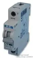
FAZ-C3/1-SP
CIRCUIT BREAKER, THERMAL MAGNETIC, 1P, 3A
⚠️ Reference pricing provided. In case of supply shortages, we will connect you with our trusted procurement partners to ensure your project's continuity.
- Manufacturer: EATON CUTLER HAMMER
- Product type: Thermal Magnetic Circuit Breakers
- Product Range:FAZ Series; Current Rating:3A; No. of Poles:1 Pole; Voltage Rating VDC:48V; Voltage Rating VAC:400V; Circuit Breaker Mounting:DIN Rail 34M1952
- No. of Poles: 1 Pole
- Product Range: FAZ Series
- Current Rating: 3A
- Voltage Rating VAC: 400V
- Voltage Rating VDC: 48V
- Circuit Breaker Mounting: DIN Rail
| Delivery and price | |
|---|---|
| Units per pack | 250 |
| Price | 33.23 € |
| Current stock | 25+ |
| Lead time | 30 days |
Datasheet

Product Guide

UL 489 and UL 1077 DIN rail miniature circuit breakers

## Application guidelines for UL 489 circuit breakers and UL 1077 supplementary protectors

**==> picture [451 x 359] intentionally omitted <==**

**----- Start of picture text -----**<br>
UL 489<br>Breaker<br>Sie. |<br>P\p<br>ca 7 UL 489<br>UL 1077 Branch<br>Internal Receptacle External<br>Receptacle<br>Electronics<br>UL 1077 UL 489<br>Branch External<br>Motor<br>Other<br>_— NN _—NN<br>Sensitive  M<br>Devices<br>UL 489<br>Branch<br>ry ——_<br>External<br>UL 489 = =F)<br>Motor<br>Branch<br>M<br>UL 1077 Motor<br>HACR Controller<br>LN<br>Example of UL 489 and UL 1077 Application<br>**----- End of picture text -----**<br>


## **UL 489 circuit breakers**

Used for branch circuit protection, internal/external receptacles, external motors and HACR equipment (heating, air conditioning and refrigeration).

## **UL 1077 supplementary protectors**

Used for overcurrent protection within appliances or electrical equipment, where branch circuit protection is already provided or not required.

**Notee:** UL 489 devices can be used in place of UL 1077; UL 1077 devices cannot be used in place of UL 489.

**ii**

**eaton corporation** UL 489 and UL 1077 DIN Rail Miniature Circuit Breakers

## UL 489 and UL 1077 DIN rail miniature circuit breakers

|**UL 489 DIN rail branch circuit breakers**||
|---|---|
|Product overview <br>2||
|Product selection||
|FAZ-NA—B curve (3–5X_I_ncurrent rating)  . . . . . . . . . . . . . . . . . . . . . . . . . . . . . . . . . . . . . . . . . . . . . . .<br>4||
|FAZ-NA—C curve (5–10X_I_ncurrent rating) . . . . . . . . . . . . . . . . . . . . . . . . . . . . . . . . . . . . . . . . . . . . . . .<br>5||
|FAZ-NA—D curve (10–20X_I_ncurrent rating)  . . . . . . . . . . . . . . . . . . . . . . . . . . . . . . . . . . . . . . . . . . . . .<br>6||
|FAZ-NA-DC—10 kAIC at 125 Vdc per pole . . . . . . . . . . . . . . . . . . . . . . . . . . . . . . . . . . . . . . . . . . . . . . .<br>7||
|Accessories<br>8||
|Technical data<br>10||
|Accessory technical data|14|
|**UL 1077 DIN rail supplementary protectors**||
|Product overview|17|
|Product selection||
|FAZ—B curve (3–5X_I_ncurrent rating)  . . . . . . . . . . . . . . . . . . . . . . . . . . . . . . . . . . . . . . . . . . . . . . . . . .<br>19||
|FAZ—C curve (5–10X_I_ncurrent rating) . . . . . . . . . . . . . . . . . . . . . . . . . . . . . . . . . . . . . . . . . . . . . . . . . .<br>20||
|FAZ—D curve (10–20X_I_ncurrent rating)  . . . . . . . . . . . . . . . . . . . . . . . . . . . . . . . . . . . . . . . . . . . . . . . .<br>21||
|FAZ—K curve (8–12X_I_ncurrent rating . . . . . . . . . . . . . . . . . . . . . . . . . . . . . . . . . . . . . . . . . . . . . . . . . .<br>22||
|FAZ—S curve (13–17X_I_ncurrent rating)  . . . . . . . . . . . . . . . . . . . . . . . . . . . . . . . . . . . . . . . . . . . . . . . .<br>23||
|FAZ—Z curve (2–3X_I_ncurrent rating)  . . . . . . . . . . . . . . . . . . . . . . . . . . . . . . . . . . . . . . . . . . . . . . . . . .<br>24||
|Accessories<br>27||
|Technical data<br>28||
|Accessory technical data|33|
|**Miniature circuit breaker application**||
|FAZ circuit breakers|37|


**eaton corporation** UL 489 and UL 1077 DIN Rail Miniature Circuit Breakers **1**

## UL 489 DIN rail branch circuit breakers

## FAZ-NA circuit breakers

## **PRODUCT OVERVIEW**

## **Optimum and efficient protection**

- Suitable for branch circuit device protection

- Thermal-magnetic overcurrent protection

- Three levels of short-circuit protection, categorized by B, C and D curves

- Trip-free design—breaker can not be defeated by holding the handle in the ON position

- Captive screws cannot be lost

- SWD (switching duty)—suitable for switching fluorescent lighting loads (In ≤ 20A)

- Fulfill UL 489, CSA C22.2 No.5 and also IEC 60947-2 Standard

- For use in applications for which UL 1077 or CSA C22.2 No.235 are also allowed

- Field installable shunt trip and auxiliary switch subsequent mounting

Optimum product quality, tested reliability and safety stand for best protection of personnel, installations and plant. Eaton’s FAZ-NA DIN rail mountable circuit breaker is designed for use in branch service applications.

- Separate version for ring-tongue connection (Type FAZ-RT), terminal screws can be removed (on both sides)

- Module width of only 17.7 mm (per pole)

- Contact Position Indicator (red/green)

## **Powerful offering for machine and system builders**

The FAZ-NA is available with B, C and D characteristics in accordance with UL[®] 489, CSA[®] C22.2 No.5; UL 1077, CSA C22.2 No.235 and IEC 60947-2. These devices are CE marked.

## **Typical applications**

Feeder and branch circuit protection

- Convenience receptacle circuits (internal/external)

- Motor control circuits

- Load circuits leaving the equipment (external)

- HACR equipment (heating, air conditioning, refrigeration) (internal/external)

- PLC I/O points

- Computers

- Power supplies

- Control instrumentation

- Relays

- UPS

- Power conditioners

## **Features**

- Complete range of UL 489 listed DIN rail mounted miniature circuit breakers up to 40A current rating

- Standard ratings of 10 kAIC up to 277/480 Vac

- Select amperages available at 14 kAIC up to 277/480 Vac and 10 kAIC up to 125 Vdc per pole

- Current limiting design provides fast short-circuit interruption that reduces the let-through energy, which can damage the circuit

- Easy installation on DIN rail

- Possibility for sealing the toggle in ON or OFF position

**FAZ-NA complies with the latest national and international standards**

## **Standards—Feeder and Branch Circuit Protection**

**UL 489** Standard for molded case circuit breakers (MCCB) for feeder and branch circuit protection. Products meet the requirements of the National Electrical Code[®] (NEC[®] ). ~~—~~ **CSA C22.2 No.5** ~~@~~ Standard for molded case circuit breakers (MCCB) for feeder and branch circuit protection (corresponds closely to UL 489 Standard). Products meet the requirements of the ~~G&S~~ Canadian Electrical Code (CEC). **RoHS** These devices are RoHS compliant. ~~RBS~~ **VDE** These devices are VDE compliant. ~~OO~~ **ABS** These devices are ABS compliant. ~~— EABs:~~

**2**

**eaton corporation** UL 489 and UL 1077 DIN Rail Miniature Circuit Breakers

FAZ-NA circuit breakers **PRODUCT OVERVIEW**

## UL 489 DIN rail branch circuit breakers

## **Tripping curves to choose from**

Eaton FAZ-NA branch circuit breakers are available with “B,” “C” and “D” tripping characteristics. B-curve devices are suitable for applications where low levels of inrush current are expected.

C-curve devices are suitable for applications where medium levels of inrush current are expected. Applications include small transformers, lighting, pilot devices, control circuits and coils. C-curve devices provide a medium magnetic trip point.

D-curve devices are suitable for applications where high levels of inrush current are expected. The high magnetic trip point prevents nuisance tripping in high inductive applications such as motors, transformers and power supplies.

Eaton FAZ-NA devices are current limiting, which means they interrupt fault currents within one half cycle of the fault. Current limiting devices offer superior protection by reducing peak let-through current and energy.

## **Device printing on front and side**

## Installation options

These branch circuit breakers are available in two terminal configurations: standard box terminals that accept multiple conductors and ring-tongue terminals, ideally suited to demanding requirements of the semi-conductor industry. All breakers mount on standard 35 mm DIN rail. Bus connectors and feeder terminal facilitate mounting and wiring of multiple miniature circuit breaker arrays in control panel assemblies. These circuit breakers can also be reverse feed.

## **Catalog Numbering System**

## **FAZ - C 6 / 1 - NA SP**

|**Breaker Family**<br>**FAZ**= FAZ UL<br>circuit breaker<br>**Trip**<br>**Characteristic**a<br>**B**= 3–5X_I_n<br>**C**= 5–10X_I_n<br>**D**= 10–20X_I_n<br>**Ampere Rating**b<br>**0.5**= 0.5A<br>**1**= 1A<br>**1.5**= 1.5A<br>**2**= 2A<br>**3**= 3A<br>**4**= 4A<br>**5**= 5A<br>**6**= 6A<br>**7**= 7A<br>**8**= 8A<br>**10**= 10A<br>**13**= 13A<br>**15**= 15A<br>**16**= 16A<br>**20**= 20A<br>**25**= 25A<br>**30**= 30A<br>**32**= 32A<br>**35**= 35A<br>**40**= 40A|**Breaker Family**<br>**FAZ**= FAZ UL<br>circuit breaker<br>**Trip**<br>**Characteristic**a<br>**B**= 3–5X_I_n<br>**C**= 5–10X_I_n<br>**D**= 10–20X_I_n<br>**Ampere Rating**b<br>**0.5**= 0.5A<br>**1**= 1A<br>**1.5**= 1.5A<br>**2**= 2A<br>**3**= 3A<br>**4**= 4A<br>**5**= 5A<br>**6**= 6A<br>**7**= 7A<br>**8**= 8A<br>**10**= 10A<br>**13**= 13A<br>**15**= 15A<br>**16**= 16A<br>**20**= 20A<br>**25**= 25A<br>**30**= 30A<br>**32**= 32A<br>**35**= 35A<br>**40**= 40A|**Breaker Family**<br>**FAZ**= FAZ UL<br>circuit breaker<br>**Trip**<br>**Characteristic**a<br>**B**= 3–5X_I_n<br>**C**= 5–10X_I_n<br>**D**= 10–20X_I_n<br>**Ampere Rating**b<br>**0.5**= 0.5A<br>**1**= 1A<br>**1.5**= 1.5A<br>**2**= 2A<br>**3**= 3A<br>**4**= 4A<br>**5**= 5A<br>**6**= 6A<br>**7**= 7A<br>**8**= 8A<br>**10**= 10A<br>**13**= 13A<br>**15**= 15A<br>**16**= 16A<br>**20**= 20A<br>**25**= 25A<br>**30**= 30A<br>**32**= 32A<br>**35**= 35A<br>**40**= 40A|
|---|---|---|
||**0.5**= 0.5A<br>**1**= 1A<br>**1.5**= 1.5A<br>**2**= 2A<br>**3**= 3A<br>**4**= 4A<br>**5**= 5A<br>**6**= 6A<br>**7**= 7A<br>**8**= 8A|**10**= 10A<br>**13**= 13A<br>**15**= 15A<br>**16**= 16A<br>**20**= 20A<br>**25**= 25A<br>**30**= 30A<br>**32**= 32A<br>**35**= 35A<br>**40**= 40A|


**Single Package Terminal SP** = Single package **Number of Poles NA** = UL 489 branch for C and D **1** = Single-pole circuit with screw curve single- **2** = Two-pole terminals pole only **3** = Three-pole **RT** = UL 489 branch **Blank** = Standard circuit with ring packaging tongue terminals **DC** = UL 489 branch circuit at 125 Vdc per pole

> a _I_ n = Rated current for instantaneous trip characteristics.

b B curve starts at 1 ampere.

**3**

**eaton corporation** UL 489 and UL 1077 DIN Rail Miniature Circuit Breakers

## UL 489 DIN rail branch circuit breakers

## FAZ-NA circuit breakers

## **PRODUCT SELECTION**

## **FAZ-NA product selection**

- UL approved (UL 489) and CSA Certified (CSA C22.2 No.5-02) as branch circuit breakers

- Interrupting capacity: 10 kA UL/CSA; 15 kA IEC 60947-2

- Current limiting device

- UL file number E235139

**==> picture [238 x 302] intentionally omitted <==**

**----- Start of picture text -----**<br>
7200 Zoe<br>3600 Specified non-tripping  a  2.55 IN:<br>current t = 1–60 s (IN < 32A)<br>1200 yA INT = 1.13 x IN for t > 1 h t = 1–120 s (IN > 32A)<br>600 PA Specified tripping current b  Type B: 3 x IN: t > 0.1 s<br>300 PA IT = 1.45 x IN for t < 1 h c  Type B: 5 x IN: t < 0.1 s<br>120<br>moe<br>60 1<br>| Ao TTI | | hE<br>30<br>PND<br>10<br>|RT<br>5<br>Lt} |<br>2<br>es 7m PP<br>1 a 7<br>ee 1 77|e<br>0.5<br>877 ee<br>0.2<br>ee<br>0.1 3<br>0.05 Poa 2 A77 B<br>0.02<br>VA<br>0.01 PT 77|<br>0.005<br>0.002<br>0.001 eeee<br>0.0005 J ee<br>1 2 3 4 5 6 7 8 9 10 15 20 30 40 50<br>I / I N<br>1.13 1.45<br>t [sec]<br>**----- End of picture text -----**<br>


**FAZ-NA UL 489 Circuit Breakers—10 kAIC, 14 kAIC B Curve (15–25A)**

**FAZ-RT UL 489 Circuit Breakers with Ring-Tongue Terminals—10 kAIC, 14 kAIC B Curve (15–25A)**

||**Single-pole**a|**two-pole**|**three-pole**|||**Single-pole**a|**two-pole**<br>**three-pole**|**two-pole**<br>**three-pole**|
|---|---|---|---|---|---|---|---|---|
|**amperes**|**catalog number**|**catalog number**|**catalog number**||**amperes**|**catalog number**|**catalog number**<br>**catalog number**||
|**B Curve (3–5X****_I_n Current Rating)**|||||**B Curve with Ring-Tongue Terminals (3–5X****_I_n Current Rating)**||||
|1|**FAZ-B1/1-NA**|**FAZ-B1/2-NA**|**FAZ-B1/3-NA**||1|**FAZ-B1/1-RT**|**FAZ-B1/2-RT**<br>**FAZ-B1/3-RT**||
|1.5|**FAZ-B1.5/1-NA**|**FAZ-B1.5/2-NA**|**FAZ-B1.5/3-NA**||1.5|**FAZ-B1.5/1-RT**|**FAZ-B1.5/2-RT**<br>**FAZ-B1.5/3-RT**||
|2|**FAZ-B2/1-NA**|**FAZ-B2/2-NA**|**FAZ-B2/3-NA**||2|**FAZ-B2/1-RT**|**FAZ-B2/2-RT**<br>**FAZ-B2/3-RT**||
|3|**FAZ-B3/1-NA**|**FAZ-B3/2-NA**|**FAZ-B3/3-NA**||3|**FAZ-B3/1-RT**|**FAZ-B3/2-RT**<br>**FAZ-B3/3-RT**||
|4|**FAZ-B4/1-NA**|**FAZ-B4/2-NA**|**FAZ-B4/3-NA**||4|**FAZ-B4/1-RT**|**FAZ-B4/2-RT**<br>**FAZ-B4/3-RT**||
|5|**FAZ-B5/1-NA**|**FAZ-B5/2-NA**|**FAZ-B5/3-NA**||5|**FAZ-B5/1-RT**|**FAZ-B5/2-RT**<br>**FAZ-B5/3-RT**||
|6|**FAZ-B6/1-NA**|**FAZ-B6/2-NA**|**FAZ-B6/3-NA**||6|**FAZ-B6/1-RT**|**FAZ-B6/2-RT**<br>**FAZ-B6/3-RT**||
|7|**FAZ-B7/1-NA**|**FAZ-B7/2-NA**|**FAZ-B7/3-NA**||7|**FAZ-B7/1-RT**|**FAZ-B7/2-RT**<br>**FAZ-B7/3-RT**||
|8|**FAZ-B8/1-NA**|**FAZ-B8/2-NA**|**FAZ-B8/3-NA**||8|**FAZ-B8/1-RT**|**FAZ-B8/2-RT**<br>**FAZ-B8/3-RT**||
|10|**FAZ-B10/1-NA**|**FAZ-B10/2-NA**|**FAZ-B10/3-NA**||10|**FAZ-B10/1-RT**|**FAZ-B10/2-RT**<br>**FAZ-B10/3-RT**||
|13|**FAZ-B13/1-NA**|**FAZ-B13/2-NA**|**FAZ-B13/3-NA**||13|**FAZ-B13/1-RT**|**FAZ-B13/2-RT**<br>**FAZ-B13/3-RT**||
|15|**FAZ-B15/1-NA**|**FAZ-B15/2-NA**|**FAZ-B15/3-NA**||15|**FAZ-B15/1-RT**|**FAZ-B15/2-RT**<br>**FAZ-B15/3-RT**||
|16|**FAZ-B16/1-NA**|**FAZ-B16/2-NA**|**FAZ-B16/3-NA**||16|**FAZ-B16/1-RT**|**FAZ-B16/2-RT**<br>**FAZ-B16/3-RT**||
|20|**FAZ-B20/1-NA**|**FAZ-B20/2-NA**|**FAZ-B20/3-NA**||20|**FAZ-B20/1-RT**|**FAZ-B20/2-RT**<br>**FAZ-B20/3-RT**||
|25|**FAZ-B25/1-NA**|**FAZ-B25/2-NA**|**FAZ-B25/3-NA**||25|**FAZ-B25/1-RT**|**FAZ-B25/2-RT**|**FAZ-B25/3-RT**|
|30|**FAZ-B30/1-NA**|**FAZ-B30/2-NA**|**FAZ-B30/3-NA**||30|**FAZ-B30/1-RT**|**FAZ-B30/2-RT**|**FAZ-B30/3-RT**|
|32|**FAZ-B32/1-NA**|**FAZ-B32/2-NA**|**FAZ-B32/3-NA**||32|**FAZ-B32/1-RT**|**FAZ-B32/2-RT**|**FAZ-B32/3-RT**|
|35b|**FAZ-B35/1-NA**|**FAZ-B35/2-NA**|**FAZ-B35/3-NA**||35b|**FAZ-B35/1-RT**|**FAZ-B35/2-RT**|**FAZ-B35/3-RT**|
|40b|**FAZ-B40/1-NA**|**FAZ-B40/2-NA**|**FAZ-B40/3-NA**||40b|**FAZ-B40/1-RT**|**FAZ-B40/2-RT**|**FAZ-B40/3-RT**|


a Two-piece order. Quantities of two per box. b 240 Vac rated only.

**4**

**eaton corporation** UL 489 and UL 1077 DIN Rail Miniature Circuit Breakers

## UL 489 DIN rail branch circuit breakers

## FAZ-NA circuit breakers **PRODUCT SELECTION**

## **FAZ-NA product selection**

- UL approved (UL 489) and CSA Certified (CSA C22.2 No.5-02) as branch circuit breakers

- Interrupting capacity: 10 kA UL/CSA; 15 kA IEC 60947-2

- Current limiting device

- UL file number E235139

**==> picture [235 x 302] intentionally omitted <==**

**----- Start of picture text -----**<br>
7200 EZ<br>3600 Specified non-tripping  a  Type C: 5 x IN: t > 0.1 s<br>1200 oo currentINT = 1.13 x IN for t > 1 h b  Type C: 10 x IN: t < 0.1 s<br>600 PVA Specified tripping current<br>300 PY IT = 1.45 x IN for t < 1 h<br>120<br>PO<br>60<br>7a eee<br>30<br>PND<br>10<br>|SIT<br>5<br>2<br>1<br>77<br>0.5<br>0.2<br>7) ee<br>0.1 2<br>0.05 rr ee 1 777 C ||<br>0.02<br>7) eel<br>0.01<br>0.005<br>0.002<br>0.001 a<br>0.0005 a<br>ee eee eee<br>1 2 3 4 5 6 7 8 9 10 15 20 30 40 50<br>I / I N<br>1.13 1.45<br>t [sec]<br>**----- End of picture text -----**<br>


## **FAZ-NA UL 489 Circuit Breakers—10 kAIC, 14 kAIC C Curve (15–25A)**

**FAZ-RT UL 489 Circuit Breakers with Ring-Tongue Terminals—10 kAIC, 14 kAIC C Curve (15–25A)**

||**Single-pole**a|**two-pole**|**three-pole**|||**Single-pole**|**two-pole**||**three-pole**|
|---|---|---|---|---|---|---|---|---|---|
|**amperes**|**catalog number**|**catalog number**|**catalog number**||**amperes**|**catalog number**|**catalog number**||**catalog number**|
|**C Curve (5–10X****_I_n Current Rating)**|||||**C Curve with Ring-Tongue Terminals (5–10X****_I_n Current Rating)**|||**Current Rating)**||
|0.5|**FAZ-C0.5/1-NA-SP**|**FAZ-C0.5/2-NA**|**FAZ-C0.5/3-NA**||0.5|**FAZ-C0.5/1-RT-SP**|**FAZ-C0.5/2-RT**<br>**FAZ-C0.5/3-RT**|||
|1|**FAZ-C1/1-NA-SP**|**FAZ-C1/2-NA**|**FAZ-C1/3-NA**||1|**FAZ-C1/1-RT-SP**|**FAZ-C1/2-RT**|**FAZ-C1/3-RT**||
|1.5|**FAZ-C1.5/1-NA-SP**|**FAZ-C1.5/2-NA**|**FAZ-C1.5/3-NA**||1.5|**FAZ-C1.5/1-RT-SP**|**FAZ-C1.5/2-RT**<br>**FAZ-C1.5/3-RT**|||
|2|**FAZ-C2/1-NA-SP**|**FAZ-C2/2-NA**|**FAZ-C2/3-NA**||2|**FAZ-C2/1-RT-SP**|**FAZ-C2/2-RT**|**FAZ-C2/3-RT**||
|3|**FAZ-C3/1-NA-SP**|**FAZ-C3/2-NA**|**FAZ-C3/3-NA**||3|**FAZ-C3/1-RT-SP**|**FAZ-C3/2-RT**|**FAZ-C3/3-RT**||
|4|**FAZ-C4/1-NA-SP**|**FAZ-C4/2-NA**|**FAZ-C4/3-NA**||4|**FAZ-C4/1-RT-SP**|**FAZ-C4/2-RT**|**FAZ-C4/3-RT**||
|5|**FAZ-C5/1-NA-SP**|**FAZ-C5/2-NA**|**FAZ-C5/3-NA**||5|**FAZ-C5/1-RT-SP**|**FAZ-C5/2-RT**|**FAZ-C5/3-RT**||
|6|**FAZ-C6/1-NA-SP**|**FAZ-C6/2-NA**|**FAZ-C6/3-NA**||6|**FAZ-C6/1-RT-SP**|**FAZ-C6/2-RT**|**FAZ-C6/3-RT**||
|7|**FAZ-C7/1-NA-SP**|**FAZ-C7/2-NA**|**FAZ-C7/3-NA**||7|**FAZ-C7/1-RT-SP**|**FAZ-C7/2-RT**|**FAZ-C7/3-RT**||
|8|**FAZ-C8/1-NA-SP**|**FAZ-C8/2-NA**|**FAZ-C8/3-NA**||8|**FAZ-C8/1-RT-SP**|**FAZ-C8/2-RT**|**FAZ-C8/3-RT**||
|10|**FAZ-C10/1-NA-SP**|**FAZ-C10/2-NA**|**FAZ-C10/3-NA**||10|**FAZ-C10/1-RT-SP**|**FAZ-C10/2-RT**<br>**FAZ-C10/3-RT**|||
|13|**FAZ-C13/1-NA-SP**|**FAZ-C13/2-NA**|**FAZ-C13/3-NA**||13|**FAZ-C13/1-RT-SP**|**FAZ-C13/2-RT**<br>**FAZ-C13/3-RT**|||
|15|**FAZ-C15/1-NA-SP**|**FAZ-C15/2-NA**|**FAZ-C15/3-NA**||15|**FAZ-C15/1-RT-SP**|**FAZ-C15/2-RT**<br>**FAZ-C15/3-RT**|||
|16|**FAZ-C16/1-NA-SP**|**FAZ-C16/2-NA**|**FAZ-C16/3-NA**||16|**FAZ-C16/1-RT-SP**|**FAZ-C16/2-RT**<br>**FAZ-C16/3-RT**|||
|20|**FAZ-C20/1-NA-SP**|**FAZ-C20/2-NA**|**FAZ-C20/3-NA**||20|**FAZ-C20/1-RT-SP**|**FAZ-C20/2-RT**<br>**FAZ-C20/3-RT**|||
|25|**FAZ-C25/1-NA-SP**|**FAZ-C25/2-NA**|**FAZ-C25/3-NA**||25|**FAZ-C25/1-RT-SP**|**FAZ-C25/2-RT**||**FAZ-C25/3-RT**|
|30|**FAZ-C30/1-NA-SP**|**FAZ-C30/2-NA**|**FAZ-C30/3-NA**||30|**FAZ-C30/1-RT-SP**|**FAZ-C30/2-RT**||**FAZ-C30/3-RT**|
|32|**FAZ-C32/1-NA-SP**|**FAZ-C32/2-NA**|**FAZ-C32/3-NA**||32|**FAZ-C32/1-RT-SP**|**FAZ-C32/2-RT**||**FAZ-C32/3-RT**|
|35b|**FAZ-C35/1-NA-SP**|**FAZ-C35/2-NA**|**FAZ-C35/3-NA**||35b|**FAZ-C35/1-RT-SP**|**FAZ-C35/2-RT**||**FAZ-C35/3-RT**|
|40b|**FAZ-C40/1-NA-SP**|**FAZ-C40/2-NA**|**FAZ-C40/3-NA**||40b|**FAZ-C40/1-RT-SP**|**FAZ-C40/2-RT**||**FAZ-C40/3-RT**|


a Option for single packaging on single-pole C and D curves only; add suffix SP when ordering.

b 240 Vac rated only.

**eaton corporation** UL 489 and UL 1077 DIN Rail Miniature Circuit Breakers

**5**

## UL 489 DIN rail branch circuit breakers

## FAZ-NA circuit breakers

## **PRODUCT SELECTION**

## **FAZ-NA product selection**

- UL approved (UL 489) and CSA Certified (CSA C22.2 No.5-02) as branch circuit breakers

- Interrupting capacity: 10 kA UL/CSA; 15 kA IEC 60947-2

- Current limiting device

- UL file number E235139

**==> picture [238 x 302] intentionally omitted <==**

**----- Start of picture text -----**<br>
7200<br>3600 Specified non-tripping  a  2.55 IN:<br>current t = 1–60 s (IN < 32A)<br>1200 va INT = 1.13 x IN for t > 1 h t = 1–120 s (IN > 32A)<br>600 PVA Specified tripping current b  Type D: 10 x IN: t > 0.1 s<br>300 avenue IT = 1.45 x IN for t < 1 h c  Type D: 20 x  IN: t < 0.1 s<br>120<br>|<br>60 1<br>7 weeee<br>30<br>eo ee<br>10 aeeee<br>5<br>2<br>1<br>1<br>0.5<br>a ee "7<br>0.2<br>|<br>0.1 a 77 3<br>0.05 2 D<br>re ee 7i777 |  ee e<br>0.02 77<br>0.01<br>a eZoe<br>0.005<br>0.002<br>0.001 a eeee<br>0.0005 es ee<br>1 2 3 4 5 6 7 8 9 10 15 20 30 40 50<br>I / I N<br>1.13 1.45<br>t [sec]<br>**----- End of picture text -----**<br>


**FAZ-NA UL 489 Circuit Breakers—10 kAIC, 14 kAIC D Curve (13–20A)**

**FAZ-RT UL 489 Circuit Breakers with Ring-Tongue Terminals—10 kAIC, 14 kAIC D Curve (13–20A)**

||**Single-pole**a|**two-pole**|**three-pole**|||**Single-pole**|**two-pole**|**three-pole**|
|---|---|---|---|---|---|---|---|---|
|**amperes**|**catalog number**|**catalog number**|**catalog number**||**amperes**|**catalog number**|**catalog number**|**catalog number**|
|**D Curve (10–20X****_I_n Current Rating)**|||||**D Curve with Ring-Tongue Terminals (10–20X****_I_n Current Rating)**|||**Current Rating)**|
|0.5|**FAZ-D0.5/1-NA-SP**|**FAZ-D0.5/2-NA**|**FAZ-D0.5/3-NA**||0.5|**FAZ-D0.5/1-RT-SP**|**FAZ-D0.5/2-RT**|**FAZ-D0.5/3-RT**|
|1|**FAZ-D1/1-NA-SP**|**FAZ-D1/2-NA**|**FAZ-D1/3-NA**||1|**FAZ-D1/1-RT-SP**|**FAZ-D1/2-RT**|**FAZ-D1/3-RT**|
|1.5|**FAZ-D1.5/1-NA-SP**|**FAZ-D1.5/2-NA**|**FAZ-D1.5/3-NA**||1.5|**FAZ-D1.5/1-RT-SP**|**FAZ-D1.5/2-RT**|**FAZ-D1.5/3-RT**|
|2|**FAZ-D2/1-NA-SP**|**FAZ-D2/2-NA**|**FAZ-D2/3-NA**||2|**FAZ-D2/1-RT-SP**|**FAZ-D2/2-RT**|**FAZ-D2/3-RT**|
|3|**FAZ-D3/1-NA-SP**|**FAZ-D3/2-NA**|**FAZ-D3/3-NA**||3|**FAZ-D3/1-RT-SP**|**FAZ-D3/2-RT**|**FAZ-D3/3-RT**|
|4|**FAZ-D4/1-NA-SP**|**FAZ-D4/2-NA**|**FAZ-D4/3-NA**||4|**FAZ-D4/1-RT-SP**|**FAZ-D4/2-RT**|**FAZ-D4/3-RT**|
|5|**FAZ-D5/1-NA-SP**|**FAZ-D5/2-NA**|**FAZ-D5/3-NA**||5|**FAZ-D5/1-RT-SP**|**FAZ-D5/2-RT**|**FAZ-D5/3-RT**|
|6|**FAZ-D6/1-NA-SP**|**FAZ-D6/2-NA**|**FAZ-D6/3-NA**||6|**FAZ-D6/1-RT-SP**|**FAZ-D6/2-RT**|**FAZ-D6/3-RT**|
|7|**FAZ-D7/1-NA-SP**|**FAZ-D7/2-NA**|**FAZ-D7/3-NA**||7|**FAZ-D7/1-RT-SP**|**FAZ-D7/2-RT**|**FAZ-D7/3-RT**|
|8|**FAZ-D8/1-NA-SP**|**FAZ-D8/2-NA**|**FAZ-D8/3-NA**||8|**FAZ-D8/1-RT-SP**|**FAZ-D8/2-RT**|**FAZ-D8/3-RT**|
|10|**FAZ-D10/1-NA-SP**|**FAZ-D10/2-NA**|**FAZ-D10/3-NA**||10|**FAZ-D10/1-RT-SP**|**FAZ-D10/2-RT**|**FAZ-D10/3-RT**|
|13|**FAZ-D13/1-NA-SP**|**FAZ-D13/2-NA**|**FAZ-D13/3-NA**||13|**FAZ-D13/1-RT-SP**|**FAZ-D13/2-RT**|**FAZ-D13/3-RT**|
|15|**FAZ-D15/1-NA-SP**|**FAZ-D15/2-NA**|**FAZ-D15/3-NA**||15|**FAZ-D15/1-RT-SP**|**FAZ-D15/2-RT**|**FAZ-D15/3-RT**|
|16|**FAZ-D16/1-NA-SP**|**FAZ-D16/2-NA**|**FAZ-D16/3-NA**||16|**FAZ-D16/1-RT-SP**|**FAZ-D16/2-RT**|**FAZ-D16/3-RT**|
|20|**FAZ-D20/1-NA-SP**|**FAZ-D20/2-NA**|**FAZ-D20/3-NA**||20|**FAZ-D20/1-RT-SP**|**FAZ-D20/2-RT**|**FAZ-D20/3-RT**|
|25|**FAZ-D25/1-NA-SP**|**FAZ-D25/2-NA**|**FAZ-D25/3-NA**||25|**FAZ-D25/1-RT-SP**|**FAZ-D25/2-RT**|**FAZ-D25/3-RT**|
|30|**FAZ-D30/1-NA-SP**|**FAZ-D30/2-NA**|**FAZ-D30/3-NA**||30|**FAZ-D30/1-RT-SP**|**FAZ-D30/2-RT**|**FAZ-D30/3-RT**|
|32|**FAZ-D32/1-NA-SP**|**FAZ-D32/2-NA**|**FAZ-D32/3-NA**||32|**FAZ-D32/1-RT-SP**|**FAZ-D32/2-RT**|**FAZ-D32/3-RT**|
|35b|**FAZ-D35/1-NA-SP**|**FAZ-D35/2-NA**|**FAZ-D35/3-NA**||35b|**FAZ-D35/1-RT-SP**|**FAZ-D35/2-RT**|**FAZ-D35/3-RT**|
|40b|**FAZ-D40/1-NA-SP**|**FAZ-D40/2-NA**|**FAZ-D40/3-NA**||40b|**FAZ-D40/1-RT-SP**|**FAZ-D40/2-RT**|**FAZ-D40/3-RT**|


a Option for single packaging on single-pole C and D curves only; add suffix SP when ordering. b 240 Vac rated only.

**6**

**eaton corporation** UL 489 and UL 1077 DIN Rail Miniature Circuit Breakers

## UL 489 DIN rail branch circuit breakers

FAZ-NA circuit breakers

**PRODUCT SELECTION**

## **FAZ-NA-DC product selection**

- UL approved (UL 489) and CSA Certified (CSA C22.2 No.5-02) as Branch Circuit Breakers

- Interrupting capacity: 10 kA at 125 Vdc UL/CSA, 10 kA at 250 Vdc

- 125 Vdc for one-pole, 250 Vdc for two-pole in series

- Current limiting device

- Polarity (+/–) sensitive and not for use on photovoltaic string application

- UL file number E235139

**FAZ-NA-DC UL 489 Circuit Breakers— 10 kAIC at 125 Vdc per pole**

|**amperes**<br>**Single-pole**a<br>**two-pole**<br>**catalog number**<br>**catalog number**<br>~~———~~|**amperes**<br>**Single-pole**a<br>**two-pole**<br>**catalog number**<br>**catalog number**<br>~~———~~|**amperes**<br>**Single-pole**a<br>**two-pole**<br>**catalog number**<br>**catalog number**<br>~~———~~|
|---|---|---|
|**C Curve (5–10X****_I_n Current Rating)**|||
|2|**FAZ-C2/1-NA-DC-SP**|**FAZ-C2/2-NA-DC**|
|3|**FAZ-C3/1-NA-DC-SP**|**FAZ-C3/2-NA-DC**|
|4|**FAZ-C4/1-NA-DC-SP**|**FAZ-C4/2-NA-DC**|
|5|**FAZ-C5/1-NA-DC-SP**|**FAZ-C5/2-NA-DC**|
|6|**FAZ-C6/1-NA-DC-SP**|**FAZ-C6/2-NA-DC**|
|7|**FAZ-C7/1-NA-DC-SP**|**FAZ-C7/2-NA-DC**|
|8|**FAZ-C8/1-NA-DC-SP**|**FAZ-C8/2-NA-DC**|
|10|**FAZ-C10/1-NA-DC-SP**|**FAZ-C10/2-NA-DC**|
|13|**FAZ-C13/1-NA-DC-SP**|**FAZ-C13/2-NA-DC**|
|15|**FAZ-C15/1-NA-DC-SP**|**FAZ-C15/2-NA-DC**|
|16|**FAZ-C16/1-NA-DC-SP**|**FAZ-C16/2-NA-DC**|
|20|**FAZ-C20/1-NA-DC-SP**|**FAZ-C20/2-NA-DC**|
|25|**FAZ-C25/1-NA-DC-SP**|**FAZ-C25/2-NA-DC**|
|30|**FAZ-C30/1-NA-DC-SP**|**FAZ-C30/2-NA-DC**|
|32|**FAZ-C32/1-NA-DC-SP**|**FAZ-C32/2-NA-DC**|
|35|**FAZ-C35/1-NA-DC-SP**|**FAZ-C35/2-NA-DC**|
|40|**FAZ-C40/1-NA-DC-SP**|**FAZ-C40/2-NA-DC**|


a Option for single packaging on single-pole C curves only; add suffix SP when ordering.

**eaton corporation** UL 489 and UL 1077 DIN Rail Miniature Circuit Breakers **7**

## UL 489 DIN rail branch circuit breakers

## FAZ-NA circuit breakers

## **ACCESSORIES**

## **Tripping signal switch Z-NHK, Z-IHK-NA**

- Design according to IEC/EN 60947-5-1, IEC/EN 62019

- Field installable

- The specified minimum voltages are per contact—take into account particularly in case of series connection

- Self-cleaning contacts

- Contact material and design particularly suitable for extra low voltage

- Z-NHK: the function of one of the two change-over contacts can be switched from “auxiliary switch” to “tripping signal switch”

- Tripping signal contact transmits message of electric tripping, not mechanical switch-off

- Test key for contact function “electrical tripping”

- Z-IHK-NA: will allow for > 480Y/277 Vac rating

**FAZ-NA UL 489 Breakers**

**==> picture [515 x 281] intentionally omitted <==**

**----- Start of picture text -----**<br>
accessory circuit Diagram Description catalog number<br>eee<br>4.14/ Two-pole auxiliary contact/trip indicating contact Z-NHK  [a]<br>4.12/ 4.12<br>4.14<br>4.11<br>1.11<br>1.14<br>1.12<br>21 Auxiliary contact Z-IHK-NA<br>13<br>r<br>4<br>14<br>22<br>Same Polarity<br>a a Shunt trip 110–415 Vac FAZ-XAA-NA110-415VAC<br>Shunt trip 12–110 Vac FAZ-XAA-NA12-110VAC<br>m,<br>,<br>Padlock hasp IS/SPE-1TE<br>**----- End of picture text -----**<br>


a Voltage of FAZ-NA circuit breaker is limited to 300V with this auxiliary contact installed.

**8**

**eaton corporation** UL 489 and UL 1077 DIN Rail Miniature Circuit Breakers

**ACCESSORIES**

## UL 489 DIN rail branch circuit breakers

FAZ-NA circuit breakers

## **FAZ-NA UL 489 Breakers, continued**

|**accessory**<br>**circuit Diagram**<br>**Description**<br>**catalog number**<br>~~iss~~|**accessory**<br>**circuit Diagram**<br>**Description**<br>**catalog number**<br>~~iss~~|**accessory**<br>**circuit Diagram**<br>**Description**<br>**catalog number**<br>~~iss~~|**accessory**<br>**circuit Diagram**<br>**Description**<br>**catalog number**<br>~~iss~~|**accessory**<br>**circuit Diagram**<br>**Description**<br>**catalog number**<br>~~iss~~|**accessory**<br>**circuit Diagram**<br>**Description**<br>**catalog number**<br>~~iss~~|
|---|---|---|---|---|---|
|||||Busbar—one-pole, 6 terminalsbcde|**Z-SV/UL-16/1P-1TE/6**|
|||||Busbar—one-pole, 12 terminalsbcde|**Z-SV/UL-16/1P-1TE/12**|
|t r wwe G|||,|Busbar—one-pole, 18 terminalsbcde<br>Busbar—two-pole, 6 terminalsbcde<br>~~SSS~~|**Z-SV/UL-16/1P-1TE/1**<br>**Z-SV/UL-16/2P-2TE/6**|
|||||Busbar—two-pole, 12 terminalsbcde|**Z-SV/UL-16/2P-2TE/12**|
|||||Busbar—two-pole, 18 terminalsbcde|**Z-SV/UL-16/2P-2TE/18**|
|||||Busbar—three-pole, 6 terminalsbcde|**Z-SV/UL-16/3P-3TE/6**|
|||||Busbar—three-pole, 12 terminalsbcde|**Z-SV/UL-16/3P-3TE/12**|
|||||Busbar—three-pole, 18 terminalsbcde|**Z-SV/UL-16/3P-3TE/18**|
|||||Three-pole busbar shroud|**ZV-BS-UL**|
|||||Extension terminal—25 mm2(2–14 AWG)|**Z-EK/35/UL**|


|Bus connector—|**Z-EB/50/UL**|
|---|---|
|conductors up to 50 mm2(~1/0 AWG)||


## b Do not cut commoning link.

c A maximum of three commoning links may be used in conjunction. Each breaker connected to the commoning link must have the same number of poles for proper use. d Not for use with ring-tongue circuit breakers.

e Bus may be center fed for high current capacity.

## **Busbar Connection Example**

**9**

**eaton corporation** UL 489 and UL 1077 DIN Rail Miniature Circuit Breakers

## UL 489 DIN rail branch circuit breakers

## FAZ-NA circuit breakers

## **TECHNICAL DATA**

## **Miniature circuit breakers FAZ-NA Connection Diagrams**

**==> picture [189 x 8] intentionally omitted <==**

**----- Start of picture text -----**<br>
Single-Pole Two-Pole Three-Pole<br>**----- End of picture text -----**<br>


## **Miniature Circuit Breakers FAZ-NA**

|**Description**<br>~~eee~~|**Description**<br>~~eee~~|
|---|---|
|**Electrical**<br>Design accordingto|UL 489, CSA C22.2 No.5, IEC 60947-2|
|Rated voltage FAZ-NA||
|UL/CSA<br>UL/CSA<br>UL/CSA<br>IEC 947-2|10 kAIC at 277/480V from 0.5A to 32A<br>14 kAIC at select amperages<br>B and C Curves (15–25A), D Curve (13–20A)<br>10 kAIC at 240 Vac for 35A and 40A<br>10 kAIC at 48 Vdc per pole<br>15 kAIC at 240/415 Vac|
|Rated voltage FAZ-NA-DC||
|UL/CSA|10 kAIC at 125 Vdc per pole|
||(two poles maximum)|
||10 kAIC at 250 Vdc with two poles connected|
||in series|
|Rated frequency|50/60 Hz|
|Characteristic|B, C, D|
|Endurance|≥ 20,000 Operations|
|Line voltage connection|Suitable for reverse feed|
|**Mechanical**||
|Frame size|45 mm|
|Device height|105 mm|
|Device width|17.7 mm per pole|
|Terminal protection|Finger and hand touch safe according to|
||BGV A3, OVE-EN 6|
|Mounting|Quick fastening with two lock-in positions on|
||IEC/EN 60715|
|Upper and lower terminals|Open mouth/lift terminals|
|Terminal capacity|One wire<br>AWG 18–6|
||Two wires<br>AWG 18–10|
|Terminal fastening torque|AWG 18-21: 21 lb-in|
||AWG 10-8: 25 lb-in|
||AWG 6: 36 lb-in|
|Mounting|Independent ofposition|
|Calibration temperature||
|UL 489, CSA C22.2 No.5|40°C|
|IEC 60947-2|30°C|


## **Dimensions Miniature Circuit Breakers**

FAZ-NA

**==> picture [151 x 164] intentionally omitted <==**

**----- Start of picture text -----**<br>
Single-Pole Two-Pole<br>f e ) fala]<br>4.13 4.13<br>(105.0) el (105.0) bog}<br>~ Sy<br>fl .70 fle) .70<br>(17.7) (17.7)<br>a 1.39<br>(35.3)<br>**----- End of picture text -----**<br>


**==> picture [80 x 163] intentionally omitted <==**

**----- Start of picture text -----**<br>
Three-Pole<br>fel<br>4.13<br>(105.0) fk<br>“a .70 l .70 ee<br>(17.7)(17.7)<br>ee 2.09<br>(53.1)<br>**----- End of picture text -----**<br>


**10**

**eaton corporation** UL 489 and UL 1077 DIN Rail Miniature Circuit Breakers

## UL 489 DIN rail branch circuit breakers

## FAZ-NA circuit breakers **TECHNICAL DATA**

## **Let-through energy Characteristic B (1–32A), 277V**

## **Characteristic C (0.5–32A), 277V**

## **Characteristic B (35–40A), 240V**

**Characteristic C (40A), 240V**

**eaton corporation** UL 489 and UL 1077 DIN Rail Miniature Circuit Breakers

**11**

## UL 489 DIN rail branch circuit breakers FAZ-NA circuit breakers **TECHNICAL DATA**

## **Characteristic D (0.5–32A), 277V**

## **Characteristic D (40A), 240V**

**12**

**eaton corporation** UL 489 and UL 1077 DIN Rail Miniature Circuit Breakers

**TECHNICAL DATA**

## UL 489 DIN rail branch circuit breakers

FAZ-NA circuit breakers

**Influence of Ambient Temperature T on Load Carrying Capacity**

|**Device Market**<br>**current rating**<br>**_I_n (a) at 40°c**<br>**_I_n (a) at Higher ambient temperature**<br>**15°c**<br>**20°c**<br>**25°c**<br>**30°c**<br>**40°c**<br>**50°c**<br>**55°c**<br>**60°c**<br>~~Eo~~|**Device Market**<br>**current rating**<br>**_I_n (a) at 40°c**<br>**_I_n (a) at Higher ambient temperature**<br>**15°c**<br>**20°c**<br>**25°c**<br>**30°c**<br>**40°c**<br>**50°c**<br>**55°c**<br>**60°c**<br>~~Eo~~|**Device Market**<br>**current rating**<br>**_I_n (a) at 40°c**<br>**_I_n (a) at Higher ambient temperature**<br>**15°c**<br>**20°c**<br>**25°c**<br>**30°c**<br>**40°c**<br>**50°c**<br>**55°c**<br>**60°c**<br>~~Eo~~|**Device Market**<br>**current rating**<br>**_I_n (a) at 40°c**<br>**_I_n (a) at Higher ambient temperature**<br>**15°c**<br>**20°c**<br>**25°c**<br>**30°c**<br>**40°c**<br>**50°c**<br>**55°c**<br>**60°c**<br>~~Eo~~|**Device Market**<br>**current rating**<br>**_I_n (a) at 40°c**<br>**_I_n (a) at Higher ambient temperature**<br>**15°c**<br>**20°c**<br>**25°c**<br>**30°c**<br>**40°c**<br>**50°c**<br>**55°c**<br>**60°c**<br>~~Eo~~|**Device Market**<br>**current rating**<br>**_I_n (a) at 40°c**<br>**_I_n (a) at Higher ambient temperature**<br>**15°c**<br>**20°c**<br>**25°c**<br>**30°c**<br>**40°c**<br>**50°c**<br>**55°c**<br>**60°c**<br>~~Eo~~|**Device Market**<br>**current rating**<br>**_I_n (a) at 40°c**<br>**_I_n (a) at Higher ambient temperature**<br>**15°c**<br>**20°c**<br>**25°c**<br>**30°c**<br>**40°c**<br>**50°c**<br>**55°c**<br>**60°c**<br>~~Eo~~|**Device Market**<br>**current rating**<br>**_I_n (a) at 40°c**<br>**_I_n (a) at Higher ambient temperature**<br>**15°c**<br>**20°c**<br>**25°c**<br>**30°c**<br>**40°c**<br>**50°c**<br>**55°c**<br>**60°c**<br>~~Eo~~|**Device Market**<br>**current rating**<br>**_I_n (a) at 40°c**<br>**_I_n (a) at Higher ambient temperature**<br>**15°c**<br>**20°c**<br>**25°c**<br>**30°c**<br>**40°c**<br>**50°c**<br>**55°c**<br>**60°c**<br>~~Eo~~|
|---|---|---|---|---|---|---|---|---|
|0.5|0.6|0.5|0.5|0.5|0.5|0.5|0.5|0.5|
|1.0|1.1|1.1|1.1|1.0|1.0|1.0|0.9|0.9|
|1.5|1.7|1.6|1.6|1.6|1.5|1.4|1.4|1.4|
|2.0|2.2|2.2|2.1|2.1|2.0|1.9|1.9|1.8|
|3.0|3.3|3.2|3.2|3.1|3.0|2.9|2.9|2.8|
|4.0|4.4|4.3|4.2|4.2|4.0|3.8|3.8|3.7|
|5.0|5.5|5.4|5.3|5.2|5.0|4.8|4.7|4.6|
|6.0|6.6|6.5|6.4|6.2|6.0|5.8|5.6|5.5|
|7.0|7.7|7.6|7.4|7.3|7.0|6.7|6.6|6.4|
|8.0|8.8|8.6|8.5|8.3|8.0|7.7|7.5|7.4|
|10.0|11.0|10.8|10.6|10.4|10.0|9.6|9.4|9.2|
|13.0|14.3|14.0|13.8|13.5|13.0|12.5|12.5|12.0|
|15.0|16.5|16.2|15.9|15.6|15.0|14.4|14.1|13.8|
|16.0|17.6|17.3|17.0|16.6|16.0|15.4|15.0|14.7|
|20.0|22.0|21.6|21.2|20.8|20.0|19.2|18.8|18.4|
|25.0|27.5|27.0|26.5|26.0|25.0|24.0|23.3|23.0|
|30.0|33.0|32.4|31.8|31.2|30.0|28.8|28.2|27.6|
|32.0|35.2|34.6|33.9|33.3|32.0|30.7|30.1|29.4|
|40.0|44.0|43.2|42.4|41.6|40.0|38.4|37.6|36.8|


## **Load Carrying Capacity of Adjoining Miniature Circuit Breakers**

||||||||1.00|||||||||
|---|---|---|---|---|---|---|---|---|---|---|---|---|---|---|---|
|**Load Factor KT [I/IN]**|aleered<br>eR)|||||**Rated Diversity Factor**|1<br>2<br>3<br>4<br>5<br>6<br>7<br>8<br>0.70<br>0.80<br>0.90<br>ECRREEE|||||||||
||||||||||**Number of Circuit Breakers**|||||||
||||**Ambient Temperature T [°C]**|||||||||||||
||Maximum Load ILat ambient temperature T: IL(T) = INK||||KT(T)|||||||||||
|**Power Loss at****_l_n**||||||||||||||||
|**_I_n [a]**<br>**characteristic B**<br>**characteristic c**<br>**characteristic D**<br>**Single-pole**<br>**two-pole**<br>**three-pole**<br>**Single-pole**<br>**two-pole**<br>**three-pole**<br>**Single-pole**<br>**two-pole**<br>**three-pole**<br>**p [W]**<br>**p [W]**<br>**p [W]**<br>**p [W]**<br>**p [W]**<br>**p [W]**<br>**p [W]**<br>**p [W]**<br>**p [W]**<br>~~ee~~||||||||||||||||
|0.5||—|—|—|1.6|3.2|4.7||1.6||3.2||4.8|||
|1||1.1|2.2|3.4|1.1|2.2|3.4||0.8||1.5||2.3|||
|1.5||2.2|4.4|6.6|1.3|2.6|3.9||1.0||2.1||3.1|||
|2||1.4|2.8|4.3|1.4|2.8|4.3||1.0||2.1||3.1|||
|3|2.1||4.2|6.4|1.2|2.4|3.6||1.2||2.4||3.6|||
|4|1.4||2.9|4.3|1.4|2.9|4.3||1.4||2.9||4.3|||
|5|1.8||3.7|5.5|1.9|3.7|5.6||1.5||2.9||4.4|||
|6|1.7||3.5|5.2|1.2|2.3|3.5||1.2||2.3||3.5|||
|7|2.0||4.0|6.0|1.4|2.8|4.3||1.4||2.8||4.3|||
|8|2.0||3.9|5.9|1.4|2.8|4.2||1.2||2.4||3.7|||
|10|1.8||3.6|5.3|1.8|3.6|5.3||1.5||3.0||4.5|||
|13|2.4||4.7|7.1|2.4|4.7|7.1||2.0||4.1||6.1|||
|15|1.9||3.8|5.6|1.9|3.8|5.6||1.5||3.1||4.6|||
|16|2.1||4.3|6.4|2.1|4.3|6.4||1.7||3.5||5.2|||
|20|2.9||5.8|8.7|2.9|5.8|8.7||1.8||3.7||5.5|||
|25|3.1||6.2|9.3|3.1|6.2|9.3||2.6||5.1||7.7|||
|30|3.0||6.0|9.0|3.0|6.0|9.0||2.7||5.4||8.1|||
|32|3.4||6.8|10.2|3.4|6.8|10.2||3.1||6.2||9.3|||
|35|4.0||8.1|12.1|3.7|7.4|11.0||3.8||7.6||11.3|||
|40|4.0||8.1|12.1|4.0|8.1|12.1||3.9||7.8||11.6|||


**13**

**eaton corporation** UL 489 and UL 1077 DIN Rail Miniature Circuit Breakers

**accessory technical Data**

## UL 489 DIN rail branch circuit breakers

## FAZ-NA circuit breakers

## **ACCESSORY TECHNICAL DATA**

## **Dimensions (mm)**

**==> picture [175 x 7] intentionally omitted <==**

**----- Start of picture text -----**<br>
Z-SV/UL-16/6 Z-SV/UL-18...12<br>**----- End of picture text -----**<br>


**==> picture [57 x 7] intentionally omitted <==**

**----- Start of picture text -----**<br>
Z-SV/UL-16.../18<br>**----- End of picture text -----**<br>


## **Z-EK/35/UL**

|**Description**|**UL 489**|**iec/en 60947-2**|
|---|---|---|
|Ue|480 Vac/96 Vdc|240/415 Vac|
|f|50/60 Hz|50/60 Hz|
|Uimp<br>Ie<br>~~oe~~|—<br>80A at 40°C<br>#2–14 AWG 60/75°C Cu<br>0.56 in|9.5 kV<br>80A at 30°C<br>2.5–35 mm2Cu<br>14 mm<br>~~a AT =~~~|
|**Z-EB/50/UL**|||
|**Description**|**UL 489**|**iec/en 60947-2**|
|Ue|480 Vac/96 Vdc|240/415 Vac|
|f|50/60 Hz|50/60 Hz|
|Uimp<br>Ie|—<br>115A at 40°C|9.5 kV<br>160A at 30°C|
|~~ii~~i|#1–14 AWG 60/75°C Cu|1.5–50 mm2Cu|
|~~t~~<br>~~a~~<br>~~>~~|0.56 in|14 mm|


## **Lockout attachment IS/SPE-ITE**

**==> picture [33 x 6] intentionally omitted <==**

**----- Start of picture text -----**<br>
ZV-BS-UL<br>**----- End of picture text -----**<br>


**==> picture [40 x 7] intentionally omitted <==**

**----- Start of picture text -----**<br>
Z-EK/35/UL<br>**----- End of picture text -----**<br>


**14**

**eaton corporation** UL 489 and UL 1077 DIN Rail Miniature Circuit Breakers

## UL 489 DIN rail branch circuit breakers

## FAZ-NA circuit breakers **ACCESSORY TECHNICAL DATA**

## **Accessories**

|**Description**|**Z-nHK**|**Z-iHK-na**|
|---|---|---|
|**Electrical**|||
|Contact function|2CO|1NO + 1NC|
|Rated voltage|230V|250V|
|Frequency|50/60 Hz|50/60 Hz|
|Rated current|2A|6A|
|Rated thermal current Ith|2A|6A|
|Utilization category AC13|||
|Rated operational current Ie|3A/250 Vac|3A/250 Vac|
|Utilization category AC15|||
|Rated operational current Ie|2A/250 Vac|2A/250 Vac|
|Utilization category DC12|||
|Rated operational current Ie|0.5A/110 Vdc|0.5A/110 Vdc<br>0.25A/220 Vdc|
|Rated insulation voltage UI|250 Vac|250 Vac|
|Minimum operational voltageper contact Umin|5 Vdc|5 Vdc|
|Minimum operational current Imin|10 mA DC|10 mA AC/DC|
|Rated peak withstand voltage Uimp(1.2/50µ)|2.5 kV|4 kV|
|Conditional short-circuit current Ikwith backupfuse 6A|1 kA|1 kA|
|Max. backupfuse, overload and short circuit|6AgL|—|
|**Mechanical**|||
|Trippingindicator “electrical tripping”|Blue/white|—|
|Frame size|45 mm|45 mm|
|Device height|80 mm|80 mm|
|Device width|8.8 mm(0.5MU)|8.8 mm(0.5MU)|
|Mounting|Onto switchingdevice|—|
|Degree ofprotection, built-in|IP40|IP40|
|Terminal protection|Finger and hand touch safe<br>Accordingto BGV A3, ÖVE-EN 6|Finger and hand touch safe<br>Accordingto BGV A3, ÖVE-EN 6|
|Terminals|Lift terminals|Lift terminals|
|Terminal capacity|20–14 AWG|0.5–2.5 mm2|
|Terminal screws|M3(Posidrive Z0)|M3(Posidrive Z0)|
|Fasteningtorque of terminal screws|7 lb-in|Max. 1.2 Nm|


**eaton corporation** UL 489 and UL 1077 DIN Rail Miniature Circuit Breakers

**15**

## UL 489 DIN rail branch circuit breakers

## FAZ-NA circuit breakers

## **ACCESSORY TECHNICAL DATA**

## **Shunt trip release FAZ-XAA-NA**

- Remote release for subsequent mounting onto FAZ-NA/RT

- Additional installation of standard auxiliary switch is possible

- Position indicator red–green

## **Connection Diagram**

## **Busbar block UL 489 (pin)**

- Tested according to UL 489

- Do not cut

- Extension terminal 35 mm[2] Z-EK/35/UL for copper conductors

- Incoming terminal 50 mm[2] Z-EB/50/UL

- For covering of not used pins, use busbar tag shrouds ZV-BS-UL

## **Connection Diagram**

|||||Three-Pole Busbar|Two-Pole Busbar|Two-Pole Busbar|Two-Pole Busbar|Single-Pole Busbar|
|---|---|---|---|---|---|---|---|---|
|**Shunt Trip Release FAZ-XAA-NA**||||**Busbar Block UL 489 (Pin)**|||**Busbar Block UL 489 (Pin)**||
|**Description**<br>**FaZ-Xaa-na12-110Vac**<br>**FaZ-Xaa-na110-415Vac**<br>**Electrical**<br>~~es ~~|||=|**Description**<br>**Electrical**||**UL 489**||**iec/en 60947-2**|
|Can be|FAZ-NA / FAZ-NA-DC /|FAZ-NA / FAZ-NA-DC /||Rated operational voltage||480/277 Vac||—|
|mounted onto|FAZ-RT|FAZ-RT||||96 Vdc|||
|Operational<br>voltage range|12–110 Vac<br>12–60 Vdc|110–415 Vac<br>110–230 Vdc||Rated frequency<br>Rated voltage||50/60 Hz<br>480 Vac||—<br>690 Vac|
|Frequency|50/60 Hz|50/60 Hz||Overvoltage category||—||III|
|**Mechanical**||||Rated impulse||—||9.5 kV|
|Frame size|45 mm|45 mm||withstand voltage Uimp|||||
|Device height|105 mm|105 mm||Rated current||80A at 40°C||80A at 30°C|
|Device width|17.5 mm|17.5 mm||Rated conditional short-||—||15 kA|
|Mounting<br>Degree of protection,<br>built-in|Quick fasteningwith two lock-inpositions on EN 50022<br>IP40<br>IP40|||circuit current AC with<br>350AgG<br>Short-circuit current||10 kA||—|
|Terminalprotection|Finger and hand touch safe accordingto BGV A3, ÖVE-EN 6|||**Mechanical**|||||
|Terminals<br>Terminal capacity<br>One and two wires|Open mouthed/lift<br>18–10 AWG|Open mouthed/lift<br>18–10 AWG||Busbar cross section<br>Flame class according to<br>UL 94||—<br>V0||16 mm2Cu<br>—|
|||||Pollution degree||—||2|
|||||Comparative trackingindex||—||CTI 600|
|||||Minimum clearance||—||> 9.5/25.4 mm|
|||||(internal/external)|||||
|||||Minimum creepage||—||> 12.7/50.8 mm|
|||||distance(internal/external)|||||
|||||Resistance to climatic||—||According to|
|||||conditions||||DIN/EN 60068|


**16**

**eaton corporation** UL 489 and UL 1077 DIN Rail Miniature Circuit Breakers

## UL 1077 DIN rail supplementary protectors

## FAZ circuit breakers **PRODUCT OVERVIEW**

## **Optimum and efficient protection**

## **Features**

- Complete range of UL 1077 recognized DIN rail mounted miniature circuit breakers up to 63A current rating

- Standard ratings of 10 kAIC up to 277/480 Vac

- Current limiting design provides fast short-circuit interruption that reduces the let-through energy, which can damage the circuit

- Suitable for supplementary protection

- Thermal-magnetic overcurrent protection

- Six levels of short-circuit protection, categorized by B, C, D, K, S, and Z curves

Optimum product quality, tested reliability and safety stand for best protection of personnel, installations and plant. Eaton’s FAZ DIN rail mountable circuit breaker is designed for use in control panel applications.

## **Powerful offering for machine and system builders**

The FAZ is available with B, C, D, K, S, and Z characteristics in accordance with UL 1077, CSA C22.2 No.235 and IEC 60947-2. These devices are CE marked.

- Trip-free design—breaker can not be defeated by holding the handle in the ON position

- Captive screws cannot be lost

- Fulfill UL 1077, CSA C22.2 No.235 and also IEC 60947-2 Standard

- Field-installable shunt trip and auxiliary switch subsequent mounting

- Module width of only 17.7 mm (per pole)

- Contact position indicator (red/green)

## **Typical applications**

Supplementary protection

   - Easy installation on DIN rail

   - Possibility for sealing the toggle in ON or OFF position

- Control circuits

- Lighting

- Business equipment

- Appliances

## **FAZ complies with the latest national and international standards**

## **Standards—Supplementary Protection**

## **UL 1077, CSA C22.2 No. 235**

Apply to supplementary protectors intended for use as overcurrent, or overvoltage or undervoltage protection within an appliance or other electrical equipment where branch circuit protection is already provided, or is not required.

**RoHS** These devices are RoHS compliant. COMPLIANT ~~is~~ **VDE** Devices with B, C, and D curves are VDE compliant. ~~Se~~

**CCC** Devices with B, C, and D curves are CCC compliant. **ABS** These devices are ABS compliant. ~~ass~~

**eaton corporation** UL 489 and UL 1077 DIN Rail Miniature Circuit Breakers

**17**

## UL 1077 DIN rail supplementary protectors

## FAZ circuit breakers

## **PRODUCT OVERVIEW**

**Discover these advanced features**

**==> picture [253 x 82] intentionally omitted <==**

**----- Start of picture text -----**<br>
Breakers install on   Captive Posidrive<br>standard DIN rail terminal screws<br>with finger and<br>back-of-hand<br>protection (IP20)<br>Available in one-, two-,  Trip-free design;<br>three-, four-pole, 1+N  breaker cannot be<br>and 3+N models defeated by holding<br>the handle in the<br>ON position<br>**----- End of picture text -----**<br>


**==> picture [253 x 28] intentionally omitted <==**

**----- Start of picture text -----**<br>
Color-coded indicator   Breaker information<br>provides breaker   printed on the front<br>status for easy   of the device for<br>troubleshooting quick identification<br>**----- End of picture text -----**<br>


## **Six tripping curves to choose from**

Eaton FAZ supplementary protectors are available with six different tripping characteristics, including Type B, C, D, K, S, and Z. Definitions for each trip curve are contained on the ordering pages and can be used to determine the optimal characteristic for your application. For example, low-level short-circuit faults in control wiring, such as PLCs, are best protected by devices with Type B trip characteristics (3–5X continuous rating of the device ( _I_ n).

Even though not required by NEC or CEC for supplementary protectors, Eaton’s FAZ devices are current limiting, which means that they interrupt fault currents within one half cycle. Current limiting devices offer superior protection by reducing peak let-through current and energy.

**==> picture [246 x 304] intentionally omitted <==**

**----- Start of picture text -----**<br>
7200 Time-current characteristic acc. to UL 1077<br>3600 To a  Conventional   c  2.55 I N :<br>non-tripping current  t = 1–60 s (IN < 32A)<br>1200 I nt  = 1.13 I N : t > 1 h t = 1–120 s (I N  < 32A)<br>600 | | b  Conventional tripping  d  Type B: 3 I N : t > 0.1 s<br>300120 current It = 1.45 IN: t < 1 h e  f  Type B: 5 IType C: 5 I N N: t < 0.1 s: t > 0.1 s<br>60 ANG ee g  Type C: 10 I N : t < 0.1 s<br>30 h  Type D: 10 I N : t > 0.1 s<br>10 Sari i  Type D: 20 IN: t < 0.1 s<br>5<br>2<br>I WSS<br>1 D<br>0.5<br>0.2<br>0.1 FINE Z B C K S<br>0.05<br>0.02<br>0.01<br>0.005<br>0.002<br>TASS<br>0.001<br>0.0005<br>1  2  3  4 5 6 7 8 9 10 15 20  30 40 50<br>I/ I n<br>1.05 1.30<br>1.13 1.45<br> (sec) t<br>**----- End of picture text -----**<br>


**Catalog Numbering System FAZ - C 6 / 1 SP Breaker Family Single Package FAZ** = Supplementary **CharacteristicTrip Ampere Rating Number of Poles SP** = Single packaging of protector **1** = Single-pole **4** = Four-pole single-pole curve B, C and **BCDKSZ** = 2–3X  = 5–10X  = 8–12X  = 13–17X  = 3–5X  = 10–20X _II_ nn _II_ nn[a][a] _II_ nn[a][a][a][a] **0.5123456** = 1A = 2A = 3A = 4A = 5A = 6A = 0.5A **13151620253032** = 13A = 15A = 16A = 20A = 25A = 30A = 32A **23** = Two-pole = Three-pole **1N3N** = 1 + neutral = 3 + neutral **Blank** = Standard  D for select amperes onlypackaging **7** = 7A **40** = 40A **8** = 8A **50** = 50A **10** = 10A **63** = 63A ~~—mT———~~ a _I_ n = Rated current for instantaneous trip characteristics. **18 eaton corporation** UL 489 and UL 1077 DIN Rail Miniature Circuit Breakers

## UL 1077 DIN rail supplementary protectors

## FAZ circuit breakers

## **PRODUCT SELECTION**

**FAZ product selection—B curve (3–5X** _**I**_ **n current rating)**

- Designed for resistive or slightly inductive loads

- Response time of instantaneous trip: 3–5X _I_ n current rating

- UL recognized and CSA Certified as supplementary protectors

- For international and domestic use (conform to IEC 60947-2)

- UL file number 177451

Suitable for applications where protection against low-level shortcircuit faults in control wiring is desired. Instantaneous trip is 3–5X continuous rating of device ( _I_ n). Applications include PLC wiring, business equipment, lighting, appliances and some motors. Low magnetic trip point.

**==> picture [238 x 302] intentionally omitted <==**

**----- Start of picture text -----**<br>
7200 | Ef<br>3600 Specified non-tripping current a  2.55 It = 1–60 s (IN:  N < 32A)<br>1200 INT = 1.13 x IN for t > 1 h t = 1–120 s (IN > 32A)<br>600300 APVA Specified tripping currentIT = 1.45 x IN for t < 1 h b c  Type B: 3 x IType B: 5 x INN: t > 0.1 s: t < 0.1 s<br>aces<br>120<br>A<br>60 1<br>| Ao TTT | | hE<br>30<br>PND<br>10<br>|RT<br>5<br>7<br>2 77 ee<br>1 a 1 77 |ee<br>0.5<br>877<br>0.2<br>ee<br>0.1 3<br>0.05 Poa 2 A B 7 ee<br>77|e<br>0.02<br>ae) Ce<br>0.01<br>0.005<br>0.002<br>0.001<br>ee eeee<br>0.0005 a ee<br>1 2 3 4 5 6 7 8 9 10 15 20 30 40 50<br>I / I N<br>1.13 1.45<br>t [sec]<br>**----- End of picture text -----**<br>


**B Curve (3–5X In Current Rating)—designed for resistive or slightly inductive loads**[a]

||**Single-pole**b|**two-pole**|**three-pole**|**Four-pole**|**Single-pole + neutral**|**three-pole + neutral**|
|---|---|---|---|---|---|---|
|**amperes**|**catalog**<br>**number**|**catalog**<br>**number**|**catalog**<br>**number**|**catalog**<br>**number**|**catalog**<br>**number**|**catalog**<br>**number**|
|1|**FAZ-B1/1-SP**|**FAZ-B1/2**|**FAZ-B1/3**|**FAZ-B1/4**|**FAZ-B1/1N**|**FAZ-B1/3N**|
|2|**FAZ-B2/1-SP**|**FAZ-B2/2**|**FAZ-B2/3**|**FAZ-B2/4**|**FAZ-B2/1N**|**FAZ-B2/3N**|
|3|**FAZ-B3/1-SP**|**FAZ-B3/2**|**FAZ-B3/3**|**FAZ-B3/4**|**FAZ-B3/1N**|**FAZ-B3/3N**|
|4|**FAZ-B4/1-SP**|**FAZ-B4/2**|**FAZ-B4/3**|**FAZ-B4/4**|**FAZ-B4/1N**|**FAZ-B4/3N**|
|5|**FAZ-B5/1-SP**|**FAZ-B5/2**|**FAZ-B5/3**|**FAZ-B5/4**|**FAZ-B5/1N**|**FAZ-B5/3N**|
|6|**FAZ-B6/1-SP**|**FAZ-B6/2**|**FAZ-B6/3**|**FAZ-B6/4**|**FAZ-B6/1N**|**FAZ-B6/3N**|
|7|**FAZ-B7/1-SP**|**FAZ-B7/2**|**FAZ-B7/3**|**FAZ-B7/4**|**FAZ-B7/1N**|**FAZ-B7/3N**|
|8|**FAZ-B8/1-SP**|**FAZ-B8/2**|**FAZ-B8/3**|**FAZ-B8/4**|**FAZ-B8/1N**|**FAZ-B8/3N**|
|10|**FAZ-B10/1-SP**|**FAZ-B10/2**|**FAZ-B10/3**|**FAZ-B10/4**|**FAZ-B10/1N**|**FAZ-B10/3N**|
|12|**FAZ-B12/1-SP**|**FAZ-B12/2**|**FAZ-B12/3**|**FAZ-B12/4**|**FAZ-B12/1N**|**FAZ-B12/3N**|
|13|**FAZ-B13/1-SP**|**FAZ-B13/2**|**FAZ-B13/3**|**FAZ-B13/4**|**FAZ-B13/1N**|**FAZ-B13/3N**|
|15|**FAZ-B15/1-SP**|**FAZ-B15/2**|**FAZ-B15/3**|**FAZ-B15/4**|**FAZ-B15/1N**|**FAZ-B15/3N**|
|16|**FAZ-B16/1-SP**|**FAZ-B16/2**|**FAZ-B16/3**|**FAZ-B16/4**|**FAZ-B16/1N**|**FAZ-B16/3N**|
|20|**FAZ-B20/1-SP**|**FAZ-B20/2**|**FAZ-B20/3**|**FAZ-B20/4**|**FAZ-B20/1N**|**FAZ-B20/3N**|
|25|**FAZ-B25/1-SP**|**FAZ-B25/2**|**FAZ-B25/3**|**FAZ-B25/4**|**FAZ-B25/1N**|**FAZ-B25/3N**|
|30|**FAZ-B30/1-SP**|**FAZ-B30/2**|**FAZ-B30/3**|**FAZ-B30/4**|**FAZ-B30/1N**|**FAZ-B30/3N**|
|32|**FAZ-B32/1-SP**|**FAZ-B32/2**|**FAZ-B32/3**|**FAZ-B32/4**|**FAZ-B32/1N**|**FAZ-B32/3N**|
|40|**FAZ-B40/1-SP**|**FAZ-B40/2**|**FAZ-B40/3**|**FAZ-B40/4**|**FAZ-B40/1N**|**FAZ-B40/3N**|
|50|**FAZ-B50/1-SP**|**FAZ-B50/2**|**FAZ-B50/3**|**FAZ-B50/4**|**FAZ-B50/1N**|**FAZ-B50/3N**|
|63|**FAZ-B63/1-SP**|**FAZ-B63/2**|**FAZ-B63/3**|**FAZ-B63/4**|**FAZ-B63/1N**|**FAZ-B63/3N**|


a In North America, these switches are UL recognized and CSA Certified as supplementary protection devices. Per the intent of NEC (National Electrical Code), Article 240, and CEC (Canadian Electrical Code), Part 1 C22.1, supplementary breakers cannot be used as a substitute for the branch circuit protective device. They can be used to provide overcurrent protection within an appliance or other electrical equipment where branch circuit overcurrent protection is already provided, or is not required.

b Option for single packaging on single-pole B, C and D curves only; add suffix SP when ordering.

**19**

**eaton corporation** UL 489 and UL 1077 DIN Rail Miniature Circuit Breakers

## UL 1077 DIN rail supplementary protectors

## FAZ circuit breakers **PRODUCT SELECTION**

**FAZ product selection—C curve (5–10X** _**I**_ **n current rating)**

|**FAZ product selection—C curve (5–10X**|**FAZ product selection—C curve (5–10X**|**FAZ product selection—C curve (5–10X****_I_n current rating) current rating)**|**FAZ product selection—C curve (5–10X****_I_n current rating) current rating)**|**FAZ product selection—C curve (5–10X****_I_n current rating) current rating)**|**n current rating) current rating)**|**n current rating) current rating)**||1.13<br>1.45||||||||||||||
|---|---|---|---|---|---|---|---|---|---|---|---|---|---|---|---|---|---|---|---|---|---|
|•Designed for inductive loads<br>•Response time of instantaneous trip: 5–10X_I_ncurrent rating<br>•UL recognized and CSA Certified as supplementary protectors|||||||7200<br>3600<br>1200<br>~~Zo~~<br>~~va~~|||||Specified non-tripping<br>current<br>INT= 1.13 x INfor t > 1 h|||||Specified non-tripping<br>for t > 1 h|aType C: 5 x IN: t > 0.1 s<br>bType C: 10 x IN: t < 0.1 s||||
|•For international and domestic use (conform to IEC 60947-2)<br>•UL file number 177451<br>Suitable for applications where medium levels of inrush current<br>are expected. Instantaneous trip is 5–10X rating of device (_I_n).<br>Applications include small transformers, lighting, pilot devices,||||||||600<br>300<br>120<br>60<br>30<br>10<br>~~nem~~<br>~~PO~~<br>~~7a~~<br>~~7OSE~~|||~~OSE~~|Specified tripping current<br>IT= 1.45 x INfor t < 1 h<br>~~eee~~<br>~~OSE~~|Specified tripping current<br>for t < 1 h<br>~~eee~~<br>~~OSE~~|||||~~eee~~<br>~~OSE~~|~~eee~~<br>~~OSE~~|~~eee~~<br>~~OSE~~|~~eee~~<br>~~OSE~~|
|control circuits, and coils. Medium magnetic trip point.|||||control circuits, and coils. Medium magnetic trip point.||t [sec]|5<br>2<br>1<br>0.5<br>0.2<br>~~al~~<br>~~7~~|||||~~al~~|~~al~~|~~al~~|~~al~~|~~al~~|~~al~~<br>~~eee~~|~~al~~<br>~~eee~~|~~al~~<br>~~eee~~|~~al~~<br>~~eee~~|
||||||||0.0005<br>0.1<br>0.05<br>0.02<br>0.005<br>0.01<br>0.002<br>0.001<br>1<br>C<br>~~7)~~<br>~~a 22~~<br>~~J~~<br>~~ee~~||||||||~~22~~|~~22~~|2<br>~~22~~|~~22~~|~~22~~|~~22~~|~~22~~|
|||||||||2<br>1||3||8<br>7<br>6<br>5<br>4||10<br>9||||40<br>30<br>20<br>15||50||
|||||||||||||I / I|I / I|N||||||||
|**C Curve (5–10X I**|**C Curve (5–10X In current rating)—designed for inductive loads**a|||||||||||||||||||||
|||**Single-pole**b|**two-pole**|||**three-pole**||**Four-pole**||||**Single-pole + neutral**||||||**three-pole + neutral**||||
|**amperes**||**catalog number**|**catalog number**|||**catalog number**||**catalog number**||||**catalog number**||||||**catalog number**||||
|0.5|**FAZ-C0.5/1-SP**||**FAZ-C0.5/2**||**FAZ-C0.5/3**|||**FAZ-C0.5/4**|||**FAZ-C0.5/1N**|||||||**FAZ-C0.5/3N**||||
|1|**FAZ-C1/1-SP**||**FAZ-C1/2**||**FAZ-C1/3**|||**FAZ-C1/4**|||**FAZ-C1/1N**|||||||**FAZ-C1/3N**||||
|1.6|**FAZ-C1.6/1-SP**||**FAZ-C1.6/2**||**FAZ-C1.6/3**|||**FAZ-C1.6/4**|||**FAZ-C1.6/1N**|||||||**FAZ-C1.6/3N**||||
|2|**FAZ-C2/1-SP**||**FAZ-C2/2**||**FAZ-C2/3**|||**FAZ-C2/4**|||**FAZ-C2/1N**|||||||**FAZ-C2/3N**||||
|3|**FAZ-C3/1-SP**||**FAZ-C3/2**||**FAZ-C3/3**|||**FAZ-C3/4**|||**FAZ-C3/1N**|||||||**FAZ-C3/3N**||||
|4|**FAZ-C4/1-SP**||**FAZ-C4/2**||**FAZ-C4/3**|||**FAZ-C4/4**|||**FAZ-C4/1N**|||||||**FAZ-C4/3N**||||
|5|**FAZ-C5/1-SP**||**FAZ-C5/2**||**FAZ-C5/3**|||**FAZ-C5/4**|||**FAZ-C5/1N**|||||||**FAZ-C5/3N**||||
|6|**FAZ-C6/1-SP**||**FAZ-C6/2**||**FAZ-C6/3**|||**FAZ-C6/4**|||**FAZ-C6/1N**|||||||**FAZ-C6/3N**||||
|7|**FAZ-C7/1-SP**||**FAZ-C7/2**||**FAZ-C7/3**|||**FAZ-C7/4**|||**FAZ-C7/1N**|||||||**FAZ-C7/3N**||||
|8|**FAZ-C8/1-SP**||**FAZ-C8/2**||**FAZ-C8/3**|||**FAZ-C8/4**|||**FAZ-C8/1N**|||||||**FAZ-C8/3N**||||
|10|**FAZ-C10/1-SP**||**FAZ-C10/2**||**FAZ-C10/3**|||**FAZ-C10/4**|||**FAZ-C10/1N**|||||||**FAZ-C10/3N**||||
|13|**FAZ-C13/1-SP**||**FAZ-C13/2**||**FAZ-C13/3**|||**FAZ-C13/4**|||**FAZ-C13/1N**|||||||**FAZ-C13/3N**||||
|15|**FAZ-C15/1-SP**||**FAZ-C15/2**||**FAZ-C15/3**|||**FAZ-C15/4**|||**FAZ-C15/1N**|||||||**FAZ-C15/3N**||||
|16|**FAZ-C16/1-SP**||**FAZ-C16/2**||**FAZ-C16/3**|||**FAZ-C16/4**|||**FAZ-C16/1N**|||||||**FAZ-C16/3N**||||
|20|**FAZ-C20/1-SP**||**FAZ-C20/2**||**FAZ-C20/3**|||**FAZ-C20/4**|||**FAZ-C20/1N**|||||||**FAZ-C20/3N**||||
|25|**FAZ-C25/1-SP**||**FAZ-C25/2**||**FAZ-C25/3**|||**FAZ-C25/4**|||**FAZ-C25/1N**|||||||**FAZ-C25/3N**||||
|30|**FAZ-C30/1-SP**||**FAZ-C30/2**||**FAZ-C30/3**|||**FAZ-C30/4**|||**FAZ-C30/1N**|||||||**FAZ-C30/3N**||||
|32|**FAZ-C32/1-SP**||**FAZ-C32/2**||**FAZ-C32/3**|||**FAZ-C32/4**|||**FAZ-C32/1N**|||||||**FAZ-C32/3N**||||
|40|**FAZ-C40/1-SP**||**FAZ-C40/2**||**FAZ-C40/3**|||**FAZ-C40/4**|||**FAZ-C40/1N**|||||||**FAZ-C40/3N**||||
|50|**FAZ-C50/1-SP**||**FAZ-C50/2**||**FAZ-C50/3**|||**FAZ-C50/4**|||**FAZ-C50/1N**|||||||**FAZ-C50/3N**||||
|63|**FAZ-C63/1-SP**||**FAZ-C63/2**||**FAZ-C63/3**|||**FAZ-C63/4**|||**FAZ-C63/1N**|||||||**FAZ-C63/3N**||||


a In North America, these switches are UL recognized and CSA Certified as supplementary protection devices. Per the intent of NEC (National Electrical Code), Article 240, and CEC (Canadian Electrical Code), Part 1 C22.1, supplementary breakers cannot be used as a substitute for the branch circuit protective device. They can be used to provide overcurrent protection within an appliance or other electrical equipment where branch circuit overcurrent protection is already provided, or is not required. b Option for single packaging on single-pole B, C and D curves only; add suffix SP when ordering.

**20**

**eaton corporation** UL 489 and UL 1077 DIN Rail Miniature Circuit Breakers

## UL 1077 DIN rail supplementary protectors

## FAZ circuit breakers **PRODUCT SELECTION**

**FAZ product selection—D curve (10–20X** _**I**_ **n current rating)**

|**FAZ product selection—D curve (10–20X**|**FAZ product selection—D curve (10–20X**|**FAZ product selection—D curve (10–20X**|**FAZ product selection—D curve (10–20X****_I_n current rating) current rating)**|**n current rating) current rating)**|**n current rating) current rating)**||1.13<br>1.45|||||||
|---|---|---|---|---|---|---|---|---|---|---|---|---|---|
|•Designed for highly inductive loads<br>•Response time of instantaneous trip: 10–20X_I_ncurrent rating<br>•UL recognized and CSA Certified as supplementary protectors<br>•For international and domestic use (conform to IEC 60947-2)||||||7200<br>3600<br>1200<br>600<br>300<br>~~Zoe~~<br>~~va~~<br>~~PY~~|||Specified non-tripping<br>current<br>INT= 1.13 x INfor t > 1 h<br>Specified tripping current<br>IT= 1.45 x INfor t < 1 h|||a2.55 IN:<br>t = 1–60 s (IN< 32A)<br>t = 1–120 s (IN> 32A)<br>bType D: 10 x IN: t > 0.1 s<br>cType D: 20 x  IN: t < 0.1 s||
|•UL file number 177451<br>Suitable for applications where high levels of inrush current are<br>expected. Instantaneous trip is 10–20X rating of device (_I_n).<br>The high magnetic trip point prevents nuisance tripping in high<br>inductive applications such as motors, transformers and<br>power supplies.||||||t [sec]|120<br>60<br>30<br>10<br>5<br>2<br>1<br>~~PO~~<br>~~Tol~~<br>~~TT TIT~~<br>~~oT TT TT~~<br>~~PD~~<br>~~PO~~<br>~~eee~~|||||||
|||||||0.0005<br>1<br>0.5<br>0.2<br>0.1<br>0.05<br>0.02<br>0.005<br>0.01<br>0.002<br>0.001<br>D<br>1<br>2<br>3<br>~~a~~<br>~~7/7~~<br>~~Pe eiZW eee~~<br>~~nell |~~<br>~~re~~<br>~~777~~<br>~~ei~~<br>~~a~~<br>~~ee~~<br>~~i oe~~<br>~~aee~~||||||||
||||||||3<br>2<br>1||10<br>9<br>8<br>7<br>6<br>5<br>4|||50<br>40<br>30<br>20<br>15||
||||||||||N<br>I / I|||||
|**D Curve (10–20X In current rating)—designed for inductive loads**||**current rating)—designed for inductive loads**||**current rating)—designed for inductive loads**a||||||||||
||**Single-pole**b<br>om||**two-pole**<br>0)|**three-pole**<br>wee|||**Four-pole**<br>eee|**Single-pole + neutral**<br>we||||**three-pole + neutral**<br>ry<br>|||
|**amperes**<br>**catalog number**||**catalog number**||**catalog number**|||**catalog number**|**catalog number**||||**catalog number**||
|0.5|**FAZ-D0.5/1-SP**||**FAZ-D0.5/2**||**FAZ-D0.5/3**||**FAZ-D0.5/4**||**FAZ-D0.5/1N**|||**FAZ-D0.5/3N**||
|1|**FAZ-D1/1-SP**||**FAZ-D1/2**||**FAZ-D1/3**||**FAZ-D1/4**||**FAZ-D1/1N**|||**FAZ-D1/3N**||
|2|**FAZ-D2/1-SP**||**FAZ-D2/2**||**FAZ-D2/3**||**FAZ-D2/4**||**FAZ-D2/1N**|||**FAZ-D2/3N**||
|3|**FAZ-D3/1-SP**||**FAZ-D3/2**||**FAZ-D3/3**||**FAZ-D3/4**||**FAZ-D3/1N**|||**FAZ-D3/3N**||
|4|**FAZ-D4/1-SP**||**FAZ-D4/2**||**FAZ-D4/3**||**FAZ-D4/4**||**FAZ-D4/1N**|||**FAZ-D4/3N**||
|5|**FAZ-D5/1-SP**||**FAZ-D5/2**||**FAZ-D5/3**||**FAZ-D5/4**||**FAZ-D5/1N**|||**FAZ-D5/3N**||
|6|**FAZ-D6/1-SP**||**FAZ-D6/2**||**FAZ-D6/3**||**FAZ-D6/4**||**FAZ-D6/1N**|||**FAZ-D6/3N**||
|7|**FAZ-D7/1-SP**||**FAZ-D7/2**||**FAZ-D7/3**||**FAZ-D7/4**||**FAZ-D7/1N**|||**FAZ-D7/3N**||
|8|**FAZ-D8/1-SP**||**FAZ-D8/2**||**FAZ-D8/3**||**FAZ-D8/4**||**FAZ-D8/1N**|||**FAZ-D8/3N**||
|10|**FAZ-D10/1-SP**||**FAZ-D10/2**||**FAZ-D10/3**||**FAZ-D10/4**||**FAZ-D10/1N**|||**FAZ-D10/3N**||
|13|**FAZ-D13/1-SP**||**FAZ-D13/2**||**FAZ-D13/3**||**FAZ-D13/4**||**FAZ-D13/1N**|||**FAZ-D13/3N**||
|15|**FAZ-D15/1-SP**||**FAZ-D15/2**||**FAZ-D15/3**||**FAZ-D15/4**||**FAZ-D15/1N**|||**FAZ-D15/3N**||
|16|**FAZ-D16/1-SP**||**FAZ-D16/2**||**FAZ-D16/3**||**FAZ-D16/4**||**FAZ-D16/1N**|||**FAZ-D16/3N**||
|20|**FAZ-D20/1-SP**||**FAZ-D20/2**||**FAZ-D20/3**||**FAZ-D20/4**||**FAZ-D20/1N**|||**FAZ-D20/3N**||
|25|**FAZ-D25/1-SP**||**FAZ-D25/2**||**FAZ-D25/3**||**FAZ-D25/4**||**FAZ-D25/1N**|||**FAZ-D25/3N**||
|30|**FAZ-D30/1-SP**||**FAZ-D30/2**||**FAZ-D30/3**||**FAZ-D30/4**||**FAZ-D30/1N**|||**FAZ-D30/3N**||
|32|**FAZ-D32/1-SP**||**FAZ-D32/2**||**FAZ-D32/3**||**FAZ-D32/4**||**FAZ-D32/1N**|||**FAZ-D32/3N**||
|40|**FAZ-D40/1-SP**||**FAZ-D40/2**||**FAZ-D40/3**||**FAZ-D40/4**||**FAZ-D40/1N**|||**FAZ-D40/3N**||
|50c|**FAZ-D50/1-SP**||**FAZ-D50/2**||**FAZ-D50/3**||**FAZ-D50/4**||**FAZ-D50/1N**|||**FAZ-D50/3N**||
|63c|**FAZ-D63/1-SP**||**FAZ-D63/2**||**FAZ-D63/3**||**FAZ-D63/4**||**FAZ-D63/1N**|||**FAZ-D63/3N**||


a In North America, these switches are UL recognized and CSA Certified as supplementary protection devices. Per the intent of NEC (National Electrical Code), Article 240, and CEC (Canadian Electrical Code), Part 1 C22.1, supplementary breakers cannot be used as a substitute for the branch circuit protective device. They can be used to provide overcurrent protection within an appliance or other electrical equipment where branch circuit overcurrent protection is already provided, or is not required.

b Option for single packaging on single-pole B, C and D curves only; add suffix SP when ordering. c IEC 60947-2 only.

**21**

**eaton corporation** UL 489 and UL 1077 DIN Rail Miniature Circuit Breakers

## UL 1077 DIN rail supplementary protectors

## FAZ circuit breakers **PRODUCT SELECTION**

**FAZ product selection—K curve (8–12X** _**I**_ **n current rating)**

- Designed for motors, transformers, and upstream electronics

- Response time of instantaneous trip: 8–12X _I_ n current rating

- UL recognized and CSA Certified as supplementary protectors

- For international and domestic use (conform to IEC 60947-2)

- UL file number 177451

Suitable for applications where medium levels of inrush current are expected. Instantaneous trip is 8–12X rating of device (Applications include small transformers, lighting, pilot devices, _I_ n). control circuits, and coils. Medium magnetic trip point.

**==> picture [229 x 273] intentionally omitted <==**

**----- Start of picture text -----**<br>
72003600 1 Specified non-tripping current<br>1200 el for t > 1 h I nt = 1.05 u   I n<br>600 Ae eeee Specified<br>300 P\\ | | | Ee tripping current<br>120 P\\L ELLE I t = 1.30 u   I n<br>for t < 1 h<br>60 we Ge<br>30<br>| XH<br>105 PONEaPENeEE<br>2<br>0.51 eeeeKNNe K eeeeee<br>0.2 ee ee ee eee<br>0.1 eeee ee ee ee<br>0.05 ee<br>0.02 ee eeee ee ee eee<br>0.01 ee<br>0.005 ee eeeee e ee ee oSeee<br>0.002 PTTET TYE<br>0.001 PT TJ<br>0.0005 PTTET TE<br>1  2  3  4 5 6 7 8 9 10 15 20  30 40 50<br>U-rated Current<br>1.13 1.45<br> (sec) t<br>**----- End of picture text -----**<br>


**designed for inductive loads K Curve (8–12X In current rating)—**[ab]

|||**Single-pole**c|**two-pole**|**three-pole**|**Four-pole**|**Single-pole + neutral**|**three-pole + neutral**|
|---|---|---|---|---|---|---|---|
|**amperes**||**catalog number**|**catalog number**|**catalog number**|**catalog number**|**catalog number**|**catalog number**|
|0.5||**FAZ-K0.5/1**|**FAZ-K0.5/2**|**FAZ-K0.5/3**|**FAZ-K0.5/4**|**FAZ-K0.5/1N**|**FAZ-K0.5/3N**|
|1||**FAZ-K1/1**|**FAZ-K1/2**|**FAZ-K1/3**|**FAZ-K1/4**|**FAZ-K1/1N**|**FAZ-K1/3N**|
|1.6||**FAZ-K1.6/1**|**FAZ-K1.6/2**|**FAZ-K1.6/3**|**FAZ-K1.6/4**|**FAZ-K1.6/1N**|**FAZ-K1.6/3N**|
|2||**FAZ-K2/1**|**FAZ-K2/2**|**FAZ-K2/3**|**FAZ-K2/4**|**FAZ-K2/1N**|**FAZ-K2/3N**|
|3||**FAZ-K3/1**|**FAZ-K3/2**|**FAZ-K3/3**|**FAZ-K3/4**|**FAZ-K3/1N**|**FAZ-K3/3N**|
|4||**FAZ-K4/1**|**FAZ-K4/2**|**FAZ-K4/3**|**FAZ-K4/4**|**FAZ-K4/1N**|**FAZ-K4/3N**|
|6||**FAZ-K6/1**|**FAZ-K6/2**|**FAZ-K6/3**|**FAZ-K6/4**|**FAZ-K6/1N**|**FAZ-K6/3N**|
|8||**FAZ-K8/1**|**FAZ-K8/2**|**FAZ-K8/3**|**FAZ-K8/4**|**FAZ-K8/1N**|**FAZ-K8/3N**|
|10||**FAZ-K10/1**|**FAZ-K10/2**|**FAZ-K10/3**|**FAZ-K10/4**|**FAZ-K10/1N**|**FAZ-K10/3N**|
|13||**FAZ-K13/1**|**FAZ-K13/2**|**FAZ-K13/3**|**FAZ-K13/4**|**FAZ-K13/1N**|**FAZ-K13/3N**|
|16||**FAZ-K16/1**|**FAZ-K16/2**|**FAZ-K16/3**|**FAZ-K16/4**|**FAZ-K16/1N**|**FAZ-K16/3N**|
|20||**FAZ-K20/1**|**FAZ-K20/2**|**FAZ-K20/3**|**FAZ-K20/4**|**FAZ-K20/1N**|**FAZ-K20/3N**|
|25||**FAZ-K25/1**|**FAZ-K25/2**|**FAZ-K25/3**|**FAZ-K25/4**|**FAZ-K25/1N**|**FAZ-K25/3N**|
|32||**FAZ-K32/1**|**FAZ-K32/2**|**FAZ-K32/3**|**FAZ-K32/4**|**FAZ-K32/1N**|**FAZ-K32/3N**|
|40||**FAZ-K40/1**|**FAZ-K40/2**|**FAZ-K40/3**|**FAZ-K40/4**|**FAZ-K40/1N**|**FAZ-K40/3N**|
|50||**FAZ-K50/1**|**FAZ-K50/2**|**FAZ-K50/3**|**FAZ-K50/4**|**FAZ-K50/1N**|**FAZ-K50/3N**|
|63||**FAZ-K63/1**|**FAZ-K63/2**|**FAZ-K63/3**|**FAZ-K63/4**|**FAZ-K63/1N**|**FAZ-K63/3N**|
|a|In North America, these switches are UL recognized and CSA Certified as supplementary protection devices. Per the intent of NEC (National Electrical Code), Article 240, and CEC (Canadian Electrical|||In North America, these switches are UL recognized and CSA Certified as supplementary protection devices. Per the intent of NEC (National Electrical Code), Article 240, and CEC (Canadian Electrical||||
||Code), Part 1 C22.1, supplementary breakers cannot be used as a substitute for the branch circuit protective device. They can be used to provide overcurrent protection within an appliance or other||||||Code), Part 1 C22.1, supplementary breakers cannot be used as a substitute for the branch circuit protective device. They can be used to provide overcurrent protection within an appliance or other|
||electrical equipment where branch circuit overcurrent protection is already provided, or is not required.|||||||
|b|These breakers are available by special order and may result in additional delivery time.||These breakers are available by special order and may result in additional delivery time.|These breakers are available by special order and may result in additional delivery time.||||
|c|Two-piece box order, quantities of 2.|||||||


**22**

**eaton corporation** UL 489 and UL 1077 DIN Rail Miniature Circuit Breakers

## UL 1077 DIN rail supplementary protectors

## FAZ circuit breakers

## **PRODUCT SELECTION**

**FAZ product selection—S curve (13–17X** _**I**_ **n current rating)**

- Designed for control circuits with high inrush

- Response time of instantaneous trip: 13–17X _I_ n current rating

- UL recognized and CSA Certified as supplementary protectors

- For international and domestic use (conform to IEC 60947-2)

- UL file number 177451

Suitable for applications where high levels of inrush current are expected. Instantaneous trip is 13–17X rating of device ( _I_ n). The high magnetic trip point prevents nuisance tripping in high inductive applications such as motors, transformers and power supplies.

## **designed for inductive loads S Curve (13–17X In current rating)—**[ab]

|**amperes**<br>**Single-pole**c<br>**two-pole**<br>**catalog number**<br>**catalog number**<br>o><br>i<br>a<br>~~Rs~~|**amperes**<br>**Single-pole**c<br>**two-pole**<br>**catalog number**<br>**catalog number**<br>o><br>i<br>a<br>~~Rs~~|**amperes**<br>**Single-pole**c<br>**two-pole**<br>**catalog number**<br>**catalog number**<br>o><br>i<br>a<br>~~Rs~~|
|---|---|---|
|1|**FAZ-S1/1**|**FAZ-S1/2**|
|2|**FAZ-S2/1**|**FAZ-S2/2**|
|3|**FAZ-S3/1**|**FAZ-S3/2**|
|4|**FAZ-S4/1**|**FAZ-S4/2**|
|6|**FAZ-S6/1**|**FAZ-S6/2**|
|10|**FAZ-S10/1**|**FAZ-S10/2**|
|16|**FAZ-S16/1**|**FAZ-S16/2**|
|20|**FAZ-S20/1**|**FAZ-S20/2**|
|25|**FAZ-S25/1**|**FAZ-S25/2**|
|32|**FAZ-S32/1**|**FAZ-S32/2**|
|40|**FAZ-S40/1**|**FAZ-S40/2**|


**==> picture [229 x 273] intentionally omitted <==**

**----- Start of picture text -----**<br>
72003600 | Specified non-tripping current<br>I nt = 1.05 u   I n<br>1200 NY foTTT for t > 1 h<br>600 [V\ | ft Specified<br>300 [\\ fF fTPptTt [tt] tripping current<br>120 p\N I t = 1.30 u   I n<br>60 ANSE for t < 1 h<br>30<br>| \ Xi<br>10 PONE TT<br>5 aNN eeeee<br>NN ee ee<br>2 a<br>1 a Ne eee<br>0.5 PoE PT A S NE<br>0.2 ee eee<br>0.1 a ee ee<br>0.05<br>ee ee eee<br>0.02<br>0.01 pTeeTP eee<br>0.005 a —<br>0.002 P| TN<br>0.001<br>0.0005 2hhli(<‘(C;:;:*;*~*:S<br>1  po 2  3  4 5 6 7 8 9 10 15 20  | 30 40 50<br>U-rated Current<br>1.05 1.30<br> (sec) t<br>**----- End of picture text -----**<br>


- a In North America, these switches are UL recognized and CSA Certified as supplementary protection devices. Per the intent of NEC (National Electrical Code), Article 240, and CEC (Canadian Electrical Code), Part 1 C22.1, supplementary breakers cannot be used as a substitute for the branch circuit protective device. They can be used to provide overcurrent protection within an appliance or other electrical equipment where branch circuit overcurrent protection is already provided, or is not required.

b These breakers are available by special order and may result in additional delivery time.

- c Two-piece box order, quantities of 2.

**23**

**eaton corporation** UL 489 and UL 1077 DIN Rail Miniature Circuit Breakers

## UL 1077 DIN rail supplementary protectors

## FAZ circuit breakers

## **PRODUCT SELECTION**

**FAZ product selection—Z curve (2–3X** _**I**_ **n current rating)**

|**FAZ product selection—Z curve (2–3X****_I_n current rating) current rating)**|**FAZ product selection—Z curve (2–3X****_I_n current rating) current rating)**|||||||||
|---|---|---|---|---|---|---|---|---|---|
|**FAZ product selection—Z curve (2–3X****_I_n current rating) current rating)**<br>•Designed for protection of electronic devices||1.05<br>1.30||||||||
|•Response time of instantaneous trip: 2–3X_I_ncurrent rating<br>•UL recognized and CSA Certified as supplementary protectors<br>•For international and domestic use (conform to IEC 60947-2)<br>Suitable for applications where low levels of inrush current<br>are expected. Instantaneous trip is 2–3X rating of device (_I_n).<br>Applications include small transformers, lighting, pilot devices,<br>control circuits, and coils. Medium magnetic trip point.||7200<br>3600<br>1200<br>600<br>300<br>120<br>60<br>30<br>10<br>5<br>2<br>1<br>0.5<br>0.2<br>0.1<br>0.05<br>0.02<br>0.01<br>0.005<br>0.002<br>0.001<br>0.0005<br>_t_(sec)<br>Specified<br>non-tripping current<br>_I_nt = 1.05 u_I_n<br>for t > 1 h<br>Specified<br>tripping current<br>_I_t = 1.30 u_I_n<br>for t < 1 h<br>**Z**<br>~~Eth~~<br>~~oS~~a<br>P\\L<br>|~~ELL~~<br>~~Cee~~<br>~~AEE~~<br>~~Pp oNNTUT~~<br>~~EE Ta~~<br>~~ee ~~ee<br>~~ae eee~~<br>~~es ~~ee<br>~~ee ~~ee<br>~~ae eee~~<br>~~es ~~ee<br>~~es ~~ee<br>~~ee eee~~<br>~~|~~<br>~~a~~<br>~~PN~~<br>~~SEH~~<br>~~|~~<br>_—<br>~~ee~~<br>~~a~~||||||||
|||1<br>2||2<br>3||4 5 6 7 8 9 10 15 20<br>30 40 50||||
|||||||U-rated Current||||
|**Z Curve (2–3X In current rating)—**||||||||||
|**designed for inductive loads**ab<br>**Single-pole**c<br>**two-pole**||**three-pole**||||**Four-pole**||||
|**amperes**<br>**catalog number**<br>**catalog number**||**catalog number**||||**catalog number**||||
|0.5<br>**FAZ-Z0.5/1**<br>**FAZ-Z0.5/2**||**FAZ-Z0.5/3**||||**FAZ-Z0.5/4**||||
|1<br>**FAZ-Z1/1**<br>**FAZ-Z1/2**||**FAZ-Z1/3**||||**FAZ-Z1/4**||||
|1.6<br>**FAZ-Z1.6/1**<br>**FAZ-Z1.6/2**||**FAZ-Z1.6/3**||||**FAZ-Z1.6/4**||||
|2<br>**FAZ-Z2/1**<br>**FAZ-Z2/2**||**FAZ-Z2/3**||||**FAZ-Z2/4**||||
|3<br>**FAZ-Z3/1**<br>**FAZ-Z3/2**||**FAZ-Z3/3**||||**FAZ-Z3/4**||||
|4<br>**FAZ-Z4/1**<br>**FAZ-Z4/2**||**FAZ-Z4/3**||||**FAZ-Z4/4**||||
|6<br>**FAZ-Z6/1**<br>**FAZ-Z6/2**||**FAZ-Z6/3**||||**FAZ-Z6/4**||||
|8<br>**FAZ-Z8/1**<br>**FAZ-Z8/2**||**FAZ-Z8/3**||||**FAZ-Z8/4**||||
|10<br>**FAZ-Z10/1**<br>**FAZ-Z10/2**||**FAZ-Z10/3**||||**FAZ-Z10/4**||||
|13<br>**FAZ-Z13/1**<br>**FAZ-Z13/2**||**FAZ-Z13/3**||||**FAZ-Z13/4**||||
|16<br>**FAZ-Z16/1**<br>**FAZ-Z16/2**||**FAZ-Z16/3**||||**FAZ-Z16/4**||||
|20<br>**FAZ-Z20/1**<br>**FAZ-Z20/2**||**FAZ-Z20/3**||||**FAZ-Z20/4**||||
|25<br>**FAZ-Z25/1**<br>**FAZ-Z25/2**||**FAZ-Z25/3**||||**FAZ-Z25/4**||||
|32<br>**FAZ-Z32/1**<br>**FAZ-Z32/2**||**FAZ-Z32/3**||||**FAZ-Z32/4**||||
|40<br>**FAZ-Z40/1**<br>**FAZ-Z40/2**||**FAZ-Z40/3**||||**FAZ-Z40/4**||||
|50<br>**FAZ-Z50/1**<br>**FAZ-Z50/2**||**FAZ-Z50/3**||||**FAZ-Z50/4**||||
|63<br>**FAZ-Z63/1**<br>**FAZ-Z63/2**||**FAZ-Z63/3**||||**FAZ-Z63/4**||||


**designed for inductive loads Z Curve (2–3X In current rating)—**[ab]

a In North America, these switches are UL recognized and CSA Certified as supplementary protection devices. Per the intent of NEC (National Electrical Code), Article 240, and CEC (Canadian Electrical Code), Part 1 C22.1, supplementary breakers cannot be used as a substitute for the branch circuit protective device. They can be used to provide overcurrent protection within an appliance or other electrical equipment where branch circuit overcurrent protection is already provided, or is not required.

b These breakers are available by special order and may result in additional delivery time.

c Two-piece box order, quantities of 2.

**24**

**eaton corporation** UL 489 and UL 1077 DIN Rail Miniature Circuit Breakers

FAZ circuit breakers

**ACCESSORIES**

## UL 1077 DIN rail supplementary protectors

**Auxiliary Contacts and Voltage Trips**

|**Module**<br>**circuit**<br>**Diagram**<br>**Description**<br>**rated operational**<br>**Voltage**<br>**catalog**<br>**number**<br>~~|~~|**Module**<br>**circuit**<br>**Diagram**<br>**Description**<br>**rated operational**<br>**Voltage**<br>**catalog**<br>**number**<br>~~|~~|**Module**<br>**circuit**<br>**Diagram**<br>**Description**<br>**rated operational**<br>**Voltage**<br>**catalog**<br>**number**<br>~~|~~|**Module**<br>**circuit**<br>**Diagram**<br>**Description**<br>**rated operational**<br>**Voltage**<br>**catalog**<br>**number**<br>~~|~~|**Module**<br>**circuit**<br>**Diagram**<br>**Description**<br>**rated operational**<br>**Voltage**<br>**catalog**<br>**number**<br>~~|~~|**Module**<br>**circuit**<br>**Diagram**<br>**Description**<br>**rated operational**<br>**Voltage**<br>**catalog**<br>**number**<br>~~|~~|**Module**<br>**circuit**<br>**Diagram**<br>**Description**<br>**rated operational**<br>**Voltage**<br>**catalog**<br>**number**<br>~~|~~|**Module**<br>**circuit**<br>**Diagram**<br>**Description**<br>**rated operational**<br>**Voltage**<br>**catalog**<br>**number**<br>~~|~~|**Module**<br>**circuit**<br>**Diagram**<br>**Description**<br>**rated operational**<br>**Voltage**<br>**catalog**<br>**number**<br>~~|~~|**Module**<br>**circuit**<br>**Diagram**<br>**Description**<br>**rated operational**<br>**Voltage**<br>**catalog**<br>**number**<br>~~|~~|**Module**<br>**circuit**<br>**Diagram**<br>**Description**<br>**rated operational**<br>**Voltage**<br>**catalog**<br>**number**<br>~~|~~|**Module**<br>**circuit**<br>**Diagram**<br>**Description**<br>**rated operational**<br>**Voltage**<br>**catalog**<br>**number**<br>~~|~~|**Module**<br>**circuit**<br>**Diagram**<br>**Description**<br>**rated operational**<br>**Voltage**<br>**catalog**<br>**number**<br>~~|~~|**Module**<br>**circuit**<br>**Diagram**<br>**Description**<br>**rated operational**<br>**Voltage**<br>**catalog**<br>**number**<br>~~|~~|**Module**<br>**circuit**<br>**Diagram**<br>**Description**<br>**rated operational**<br>**Voltage**<br>**catalog**<br>**number**<br>~~|~~|**Module**<br>**circuit**<br>**Diagram**<br>**Description**<br>**rated operational**<br>**Voltage**<br>**catalog**<br>**number**<br>~~|~~|**Module**<br>**circuit**<br>**Diagram**<br>**Description**<br>**rated operational**<br>**Voltage**<br>**catalog**<br>**number**<br>~~|~~||
|---|---|---|---|---|---|---|---|---|---|---|---|---|---|---|---|---|---|
|**Standard Auxiliary Contacts**||||||||||||||||||
|||||||||||||||• 1NO/1NC|230 Vac|**FAZ-XHIN11**||
|||||||||||||||• Installs on left side of FAZ or shunt trip||||
|||||||||||||||• Max. one per FAZ (1077) device||||
|||||||||||||||• Switches when FAZ is tripped||||
|||||||||||||||electrically or manually||||
|||||12||||||14||||• 1 changeover contact<br>• Installs on left side of FAZ or shunt trip|230 Vac|**FAZ-XHINW1**||
|||||||||||||||• Max. one per FAZ (1077) device||||
|||||||||||||||• Switches when FAZ is tripped||||
|||||||||||||||electrically or manually||||
|||||||||11||||||||||
|**Auxiliary/Trip Indicating Contact**||||||||||||||||||
|||||||||||||||• Small selector screw changes mode|230 Vac|**FAZ-XAM002**||
|||||||||||||||• Two Form C (changeover) contacts||||
|||||||||||||||• Installs on left side of FAZ or||||
|Two-pole auxiliary mode<br>shunt trip<br>• Auxiliary contacts switch when FAZ is<br>tripped electrically or manually<br>• Trip indicating contact switches only<br>when FAZ is tripped electrically<br>~~/~~||||||||||||||||||
|Trip indicating mode|||||||Trip indicating mode|||||||||||
|**Undervoltage Trip**||||||||||||||||||
|||||||||||||||• Prevents FAZ from operating unless|115 Vac|**FAZ-XUA(115VAC)**||
|||||||||||||||voltage is present||||
|||||||||||||||• Installs on left side of FAZ||||
||||||||D1|||||||• Includes test button|230 Vac|**FAZ-XUA(230VAC)**||
||||||U|||||||||||||
||||||||D2||||||||400 Vac|**FAZ-XUA(400VAC)**||
|**Shunt Trip**||||||||||||||||||
|||||||||||||||• Allows remote trip of FAZ|12–110 Vac|**FAZ-XAA-C-12-110VAC**||
|||||||||||||||• Installs on left side of FAZ|12–60 Vdc|||
|||||||||C1||||||||||
|||||||||C2|||||||110–415 Vac<br>110–230 Vdc|**FAZ-XAA-C-110-415VAC**||


## **Allowable Combinations of Accessories**

**==> picture [368 x 79] intentionally omitted <==**

**----- Start of picture text -----**<br>
1 6 eo fP R E e e FB<br>AUX AUX FAZ AUX AUX FAZ FAZ<br>TRIP TRIP<br>or or<br>Circuit Shunt Circuit UnderV Circuit<br>Breaker Trip Breaker Trip Breaker<br>7 h ?Hy ||Bo HeAo| ee ife ||<br>**----- End of picture text -----**<br>


**25**

**eaton corporation** UL 489 and UL 1077 DIN Rail Miniature Circuit Breakers

## UL 1077 DIN rail supplementary protectors

## FAZ circuit breakers

## **ACCESSORIES**

## **Busbar System**

|**Description**||||**rated operational**<br>**current**|**number of poles**<br>**per Device**|**number of**<br>**terminals**|**catalog**<br>**number**a|
|---|---|---|---|---|---|---|---|
|**Without Auxiliary Contacts**||||||||
|For connecting FAZ supplementary|For connecting FAZ supplementary|||80A|1|57|**BB-UL-18/1P-1M/57**|
|protectors without auxiliary contacts.||||||||
|May be fed from line or load side.||||||||
||||||2|56|**BB-UL-18/2P-2M/56**|
|||||||||
||||||3|57|**BB-UL-18/3P-3M/57**|
||FAZ<br>FAZ<br>FAZ|||||||
|||||100A|1|57|**BB-UL-25/1P-1M/57**|
||~~alale~~||||2<br>56<br>**BB-UL-25/2P-2M/56**<br>~~BC~~|||
||||||3|57|**BB-UL-25/3P-3M/57**|
|||||||||
|||||||||
|**Auxiliary/Trip Indicating Contact**||||||||
|For connecting FAZ supplementary|For connecting FAZ supplementary|||80A|1|37|**BB-UL-18/1P-1,5M/37**|
|protectors with auxiliary contacts.|||protectors with auxiliary contacts.|||||
|May be fed from line or load side.||||||||
||||||2|46|**BB-UL-18/2P+AS-2,5M/46**|
|||||||||
||FAZ<br>FAZ<br>a ~~@ f~~a~~l 2]~~|||100A<br>~~a~~|3<br>1<br>~~a~~|48<br>37<br>~~a~~|**BB-UL-18/3P+AS-3,5M/48**<br>**BB-UL-25/1P-1,5M/37**<br>~~a~~|
|||||||||
|||||||||
||~~|}~~<br>~~Fe Pa)~~||||2|46|**BB-UL-25/2P+AS-2,5M/46**|
||||||3|48|**BB-UL-25/3P+AS-3,5M/48**|


a Bus may be center fed for high current capacity.

**26**

**eaton corporation** UL 489 and UL 1077 DIN Rail Miniature Circuit Breakers

FAZ circuit breakers **ACCESSORIES**

## UL 1077 DIN rail supplementary protectors

## **Pin Type Incoming Supply Terminals**

## **Bus Incoming Supply Terminals**

|**accessories**|**accessories**|**accessories**|**accessories**|**accessories**|**accessories**|**accessories**|**accessories**|**accessories**|**accessories**|**accessories**|**accessories**|**accessories**|**accessories**|**accessories**|**accessories**|**accessories**|||**Description**|**installation**|**catalog**<br>**number**<br>~~me~~|**catalog**<br>**number**<br>~~me~~|||**accessories**|**accessories**|**accessories**|**accessories**|**accessories**|**accessories**|**accessories**|**accessories**|**accessories**|**accessories**|**accessories**|**accessories**|**accessories**|**accessories**|**accessories**|**accessories**||||**Description**|**Description**|**installation**|**catalog**<br>**number**|
|---|---|---|---|---|---|---|---|---|---|---|---|---|---|---|---|---|---|---|---|---|---|---|---|---|---|---|---|---|---|---|---|---|---|---|---|---|---|---|---|---|---|---|---|---|---|---|---|
|**Incoming Terminal**||||||||||||**Incoming Terminal**||||||||||||**Incoming Terminal**||||||||||||||||||||||||
||||||||||||||||||||• Accommodates||**BB-UL-TEP/35**|||||||||||||||||||||||• 50 mm|• 50 mm2||**BB-UL-TE/50**|
|~~ye~~<br>\|||||||||||||||||||conductors from<br>6–35 mm2/<br>#10–2 AWG<br>• 4–5.5 Nm/<br>35–50 lb-in<br>• Two- and<br>three-pole|||||• #14–1 AWG<br>• 75 Deg wire<br>• 115 A/Y, 480V UL<br>• 160 A/Y 690V IEC<br>**Busbar End Cap**<br>~~ne~~||||||||||||||||||||||||
||||||||||||||||||||||||||**accessories**|||||||||||||||||||**Description**||**poles**|**catalog**<br>**number**|
|||||||||||||||||||||||||**Fork Connector**|||||**Fork Connector**|||||||||||||||• Install after|• Install after|2 and 3|**BB-UL-EC/3**|
|**Pin Type Incoming Supply Terminals—Single-Phase Only**||||||||||||||||||||||||||||||||||||||||||||• Protects end|cutting busbar<br>• Protects end|||
|**accessories**|||||||||||||||||||**Description**|**poles**||**catalog**<br>**number**|||||||||||||||||||||||of busbar|||
|||||||||||||||||||||||||||||||||||||||||||||||||
|||||||||||||||||||||||||||||||||||||||||||||||||
||||||||||||||||||||• Accommodates|||**BB-UL-TEPA/35**||||||||||||||||||||||||||
||||||||||||||||||||conductors from|||||||||||||||||||||||||||||
||||||||||||||||||||6–35 mm2/|||||||||||||||||||||||||||||
|||||||||||C|C|C|C|C|C|C|||#10–1/10 AWG<br>• 4–5.5 Nm/|||||||||||||||||||||||||||1|**BB-UL-EC/1**|


- **catalog**

- **accessories Description poles number** • Accommodates **BB-UL-TEPA/35** conductors from 6–35 mm[2] / #10–1/10 AWG

- • 4–5.5 Nm/ 35–50 Ib-in

- [C]

## **Protective Accessories**

|**Protective Accessories**|**Protective Accessories**<br>**accessories**|**Protective Accessories**<br>**accessories**|**Protective Accessories**<br>**accessories**|**Protective Accessories**<br>**accessories**|**Protective Accessories**<br>**accessories**|**Protective Accessories**<br>**accessories**|**Protective Accessories**<br>**accessories**|**Protective Accessories**<br>**accessories**|**Protective Accessories**<br>**accessories**|**Protective Accessories**|**Protective Accessories**|**Protective Accessories**|**Protective Accessories**<br>**Description**|**catalog**<br>**number**<br>~~mee ~~|~~SS OO~~<br>~~UU—C~~|
|---|---|---|---|---|---|---|---|---|---|---|---|---|---|---|---|
|**Busbar Terminal Cover**||||||||||||||||
|||||||~~FF~~|||||||For covering<br>unused terminals|**BB-IP/5**||
|||||||||||||||||
||||||||||||||||||
|||||||||||||||||
|||||||||||||||||
|||||||||||||||||
|**Padlock Hasp**||||||||||||||||
|||||pe|pe|pe|pe|pe|pe|pe|pe|pe|• Prevents reactivation<br>of the device during<br>maintenance<br>• Holds one padlock|**IS/SPE-1TE**||


**27**

**eaton corporation** UL 489 and UL 1077 DIN Rail Miniature Circuit Breakers

## UL 1077 DIN rail supplementary protectors

## FAZ circuit breakers

## **TECHNICAL DATA**

## **Technical Data**

**==> picture [515 x 15] intentionally omitted <==**

**----- Start of picture text -----**<br>
Description B curve c curve D curve<br>**----- End of picture text -----**<br>


|**Electrical**||||
|---|---|---|---|
|Approvals|UR(UL 1077), CSA(CSA 22.2 No. 235), CE|||
|Standards|IEC/EN 60947-2|||
|Short-circuit tripresponse|3–5_I_n|5–10_I_n|10–20_I_n|
|**Supplementary Protectors—UL/CSA**||||
|Current range|1–63A|0.5–63A|0.5–40A|
|Maximum voltage ratings—UL/CSA||||
|Single-pole, single-pole + neutral|277 Vac|277 Vac|277 Vac|
||48 Vdc|48 Vdc|48 Vdc|
|Two-, three-pole, four-pole and||||
|three-pole + neutral|480Y/277 Vac|480Y/277 Vac|480Y/277 Vac|
|Twopoles in series|96 Vdc|96 Vdc|96 Vdc|
|Thermal tripping characteristics||||
|Single-pole<br>Multi-pole|1.35 x In@ 40°C<br>1.45 x In@ 40°C|1.35 x In@ 40°C<br>1.45 x In@ 40°C|1.35 x In@ 40°C<br>1.45 x In@ 40°C|
|Short-circuit ratings (at max. voltage)||||
|Single-pole|10 kA (5 kA for 40–63A device)|10 kA (5 kA for 40–63A device)|5 kA|
|Two-, three-pole|10 kA (5 kA for 40–63A device)|10 kA (5 kA for 40–63A device)|5 kA|
|Single-pole|10 kA @ 48 Vdc|10 kA @ 48 Vdc|10 kA @ 48 Vdc|
|Twopoles in series|10 kA @ 96 Vdc|10 kA @ 96 Vdc|10 kA @ 96 Vdc|
|**Miniature Circuit Breaker—IEC**||||
|Current range|1–63A|0.5–63A|0.5–63A|
|Maximum voltage ratings—IEC 68898-1||||
|Single-pole|230 Vac|230 Vac|230 Vac|
|Two-, three-pole|230/400 Vac|230/400 Vac|230/400 Vac|
|Maximum voltage ratings—IEC 60947-2||||
|Single-pole|240 Vac|240 Vac|240 Vac|
||48 Vdc|48 Vdc|48 Vdc|
|Two-, three-pole|240/415 Vac|240/415 Vac|240/415 Vac|
|Twopoles in series|96 Vdc|96 Vdc|96 Vdc|
|Thermal tripping characteristics||||
|Single-pole<br>Multi-pole|> 1 hour @ 1.05 x In<br>< 1 hour @ 1.3 x In|> 1 hour @ 1.05 x In<br>< 1 hour @ 1.3 x In|> 1 hour @ 1.05 x In<br>< 1 hour @ 1.3 x In|
|Interrupt ratings (at max. voltage)||||
|IEC 60947-2|15 kA|15 kA|15 kA (10 kA for 50 and 63A)|
|IEC 60898|10 kA|10 kA|10 kA (50 and 63A not available)|
|Operational switching capacity|7.5 kA|7.5 kA|7.5 kA|
|Max. backup fuse [gL/gG]|125A|125A|125A|
|Rated impulse withstand—_U_imp<br>Rated insulation voltage—_U_i|4000 Vac<br>440 Vac|4000 Vac<br>440 Vac|4000 Vac<br>440 Vac|
|**Environmental/General**||||
|Selectivity class|3|3|3|
|Lifespan (operations)|> 10,000 (1 operation = ON/OFF)|> 10,000 (1 operation = ON/OFF)|> 10,000 (1 operation = ON/OFF)|
|Shock (IEC 68-2-22)|10g–120 ms|10g–120 ms|10g–120 ms|
|Operating temperature range|–40 to +167°F (–40 to +75°C)|–40 to +167°F (–40 to +75°C)|–40 to +167°F (–40 to +75°C)|
|Shipment and short-term storage|–40 to +185°F (–40 to +85°C)|–40 to +185°F (–40 to +85°C)|–40 to +185°F (–40 to +85°C)|
|Housingmaterial|Nylon|Nylon|Nylon|
|**Mechanical**||||
|Standard front dimension||||
|Device height|80 mm|80 mm|80 mm|
|Terminal protection|Finger and back-of-hand proof to IEC 536|Finger and back-of-hand proof to IEC 536|Finger and back-of-hand proof to IEC 536|
|Mounting width per pole|17.5 mm|17.5 mm|17.5 mm|
|Mounting|IEC/EN 60715 top-hat rail|IEC/EN 60715 top-hat rail|IEC/EN 60715 top-hat rail|
|Degree of protection|IP20|IP20|IP20|
|Terminals top and bottom|Twin-purpose terminals|Twin-purpose terminals|Twin-purpose terminals|
|Supply connection|Line or load side|Line or load side|Line or load side|
|Terminal capacity [mm2]|1 x 25 (AWG 4–18)/2 x 10 (AWG 8–18)|1 x 25 (AWG 4–18)/2 x 10 (AWG 8–18)|1 x 25 (AWG 4–18)/2 x 10 (AWG 8–18)|
|Torque|2.4 Nm|2.4 Nm|2.4 Nm|
|Imperial torque|21 lb-in (AWG 18–12), 25 lb-in|21 lb-in (AWG 18–12), 25 lb-in|21 lb-in (AWG 18–12), 25 lb-in|
||(AWG 10–8), 36 lb-in (AWG 6–4)|(AWG 10–8), 36 lb-in (AWG 6–4)|(AWG 10–8), 36 lb-in (AWG 6–4)|
|Thickness of busbar material|0.8–2 mm|0.8–2 mm|0.8–2 mm|
|Mounting position|As required|As required|As required|


**28**

**eaton corporation** UL 489 and UL 1077 DIN Rail Miniature Circuit Breakers

## UL 1077 DIN rail supplementary protectors

## FAZ circuit breakers **TECHNICAL DATA**

## **Technical Data (continued)**

**==> picture [515 x 15] intentionally omitted <==**

**----- Start of picture text -----**<br>
Description K curve S curve Z curve<br>**----- End of picture text -----**<br>


|**Electrical**||||
|---|---|---|---|
|Approvals|UR(UL 1077), CSA(CSA 22.2 No. 235), CE|||
|Standards|IEC/EN 60947-2, E177451, 204453|||
|Short-circuit tripresponse|8–12_I_n|13–17_I_n|2–3_I_n|
|**Supplementary Protectors—UL/CSA**||||
|Current range|0.5–63A|0.5–40A|1–63A|
|Maximum voltage ratings—UL/CSA||||
|Single-pole, single-pole + neutral|277 Vac|277 Vac|277 Vac|
||48 Vdc|48 Vdc|48 Vdc|
|Two-, three-, four-pole and||||
|three-pole + neutral|480Y/277 Vac|480Y/277 Vac|480Y/277 Vac|
|Twopoles in series|96 Vdc|96 Vdc|96 Vdc|
|Thermal tripping characteristics||||
|Single-pole<br>Multi-pole|1.35 x In@ 40°C<br>1.45 x In@ 40°C|1.35 x In@ 40°C<br>1.45 x In@ 40°C|1.35 x In@ 40°C<br>1.45 x In@ 40°C|
|Short-circuit ratings (at max. voltage)||||
|Single-pole|5 kA @ 277 Vac|5 kA @ 277 Vac|5 kA @ 277 Vac|
|Single-pole + neutral|5 kA @ 277 Vac|5 kA @ 277 Vac|5 kA @ 277 Vac|
|Two-, three-, four-pole|5 kA @ 480Y/277 Vac|5 kA @ 480Y/277 Vac|5 kA @ 480Y/277 Vac|
|Twopoles in series|—|—|—|
|**Miniature Circuit Breaker—IEC**||||
|Current range|0.5–63A|0.5–40A|1–63A|
|Maximum voltage ratings—IEC 60947-2||||
|Single-pole, single-pole + neutral|240 Vac|240 Vac|240 Vac|
|Two-, three-, four-pole,||||
|three-pole + neutral|240/415 Vac|240/415 Vac|240/415 Vac|
|Thermal tripping characteristics||||
|Single-pole<br>Multi-pole|> 1 Hour @ 1.05 x In<br>< 1 Hour @ 1.3 x In|> 1 Hour @ 1.05 x In<br>< 1 Hour @ 1.3 x In|> 1 Hour @ 1.05 x In<br>< 1 Hour @ 1.3 x In|
|Interrupt ratings (at max. voltage)||||
|IEC 60947-2|15 kA|10 kA|10 kA|
|Operational switching capacity|7.5 kA|7.5 kA|7.5 kA|
|Max. backup fuse [gL/gG]|125A|125A|125A|
|Rated impulse withstand—_U_imp<br>Rated insulation voltage—_U_i|4000 Vac<br>440 Vac|4000 Vac<br>440 Vac|4000 Vac<br>440 Vac|
|**Environmental/General**||||
|Selectivity class|3|3|3|
|Lifespan (operations)|> 10,000 (1 operation = ON/OFF)|> 10,000 (1 operation = ON/OFF)|> 10,000 (1 operation = ON/OFF)|
|Shock (IEC 68-2-22)|10g–120 ms|10g–120 ms|10g–120 ms|
|Operating temperature range|–40 to +167°F (–40 to +75°C)|–40 to +167°F (–40 to +75°C)|–40 to +167°F (–40 to +75°C)|
|Shipment and short-term storage|–40 to +185°F (–40 to +85°C)|–40 to +185°F (–40 to +85°C)|–40 to +185°F (–40 to +85°C)|
|Housingmaterial|Nylon|Nylon|Nylon|
|**Mechanical**||||
|Standard front dimension||||
|Device height|80 mm|80 mm|80 mm|
|Terminal protection|Finger and back-of-hand proof to IEC 536|Finger and back-of-hand proof to IEC 536|Finger and back-of-hand proof to IEC 536|
|Mounting width per pole|17.7 mm|17.7 mm|17.7 mm|
|Mounting|IEC/EN 60715 top-hat rail|IEC/EN 60715 top-hat rail|IEC/EN 60715 top-hat rail|
|Degree of protection|IP20|IP20|IP20|
|Terminals top and bottom|Twin-purpose terminals|Twin-purpose terminals|Twin-purpose terminals|
|Supply connection|Line or load side|Line or load side|Line or load side|
|Terminal capacity [mm2]|1 x 25 (AWG 4–18) / 2 x 10 (AWG 8–18)|1 x 25 (AWG 4–18) / 2 x 10 (AWG 8–18)|1 x 25 (AWG 4–18) / 2 x 10 (AWG 8–18)|
|Torque|2.4 Nm|2.4 Nm|2.4 Nm|
|Imperial torque|21 lb-in (AWG 18–12), 25 lb-in|21 lb-in (AWG 18–12), 25 lb-in|21 lb-in (AWG 18–12), 25 lb-in|
||(AWG 10–8), 36 lb-in (AWG 6–4)|(AWG 10–8), 36 lb-in (AWG 6–4)|(AWG 10–8), 36 lb-in (AWG 6–4)|
|Thickness of busbar material|0.8–2 mm|0.8–2 mm|0.8–2 mm|
|Mounting position|As required|As required|As required|


**29**

**eaton corporation** UL 489 and UL 1077 DIN Rail Miniature Circuit Breakers

## UL 1077 DIN rail supplementary protectors

## FAZ circuit breakers

## **TECHNICAL DATA**

## **Let-through energy I[2] t Characteristic B and C**

## **Let-through current ID Characteristic B and C**

**==> picture [466 x 249] intentionally omitted <==**

**----- Start of picture text -----**<br>
[A∫i [2][2] dts] 108 [5] 63 A 50 A  [A] l D 1098 [4] 63 A<br>6 40 A  7 40 A  [50 A ]<br>4 32 A 25 A 20 A 16 A  6 25 A 16 A 32 A 20 A<br>13 A  5 13 A<br>10 A  10 A<br>4<br>6 A<br>2 4 A<br>1.5 6 A 4 A  3 3 A<br>10 [4] 3 A<br>8 2<br>2 A<br>6<br>2 A  1.5<br>4<br>10 [3]<br>2 1 A<br>1.5 0.5 A<br>1  A<br>10 [3] 0.5 A  5<br>8<br>6<br>4<br>3<br>2<br>0.5 1 1.5 2 3 4 5 6 7 8 910 15 0.5 1 1.5 2 3 4 5 6 7 8 910 15<br>I cc rms [kA] I cc rms [kA]<br>**----- End of picture text -----**<br>


## **Characteristic D**

## **Characteristic D**

**==> picture [190 x 249] intentionally omitted <==**

**----- Start of picture text -----**<br>
[A∫i [2][2] dts] 108 [5] 40 A 32 A<br>25 A<br>6 20 A<br>16 A<br>13 A<br>4<br>10 A<br>6 A<br>2<br>1.5<br>10 [4]<br>8<br>6<br>4<br>2<br>1.5<br>10 [3]<br>8<br>6<br>4<br>0.5 1 1.5 2 3 4 5 6 7 8 910 15<br>I cc rms [kA]<br>**----- End of picture text -----**<br>


**==> picture [197 x 247] intentionally omitted <==**

**----- Start of picture text -----**<br>
l D 109 [4]<br>[A] 8 40 A 32 A<br>7 25 A<br>20 A<br>6 16 A<br>13 A<br>5 10 A<br>6 A<br>4<br>3<br>2<br>1.5<br>10 [3]<br>5<br>2<br>0.5 1 1.5 2 3 4 5 6 7 8 910 15<br>I cc rms [kA]<br>**----- End of picture text -----**<br>


**30**

**eaton corporation** UL 489 and UL 1077 DIN Rail Miniature Circuit Breakers

## UL 1077 DIN rail supplementary protectors

## FAZ circuit breakers **TECHNICAL DATA**

## **Let-through energy I[2] t Characteristic K**

## **Characteristic S**

**==> picture [209 x 278] intentionally omitted <==**

**----- Start of picture text -----**<br>
l D 10 [4]<br>[A]<br>8<br>6 63 A 50 A<br>40 A<br>32 A<br>20 A  [25 A ]<br>13 A 16 A<br>4<br>10 A<br>6 A<br>3 4 A<br>2 2 A<br>1.6 A<br>1.5<br>1 A<br>10 [3]<br>5<br>0.5 A<br>0.5 1 1.5 2 3 4 5 6 7 8 9 10<br>I cc rms [kA]<br>3 A<br>**----- End of picture text -----**<br>


**==> picture [191 x 278] intentionally omitted <==**

**----- Start of picture text -----**<br>
l D 10 [4]<br>[A]<br>8<br>6 40 A<br>32 A<br>25 A<br>20 A<br>16 A<br>10 A<br>4<br>6 A<br>4 A<br>3<br>2 A<br>2<br>1 A<br>1.5<br>10 [3]<br>5<br>0.5 1 1.5 2 3 4 5 6 7 8 9 10<br>I cc rms [kA]<br>3 A<br>**----- End of picture text -----**<br>


## **Characteristic Z**

**==> picture [209 x 277] intentionally omitted <==**

**----- Start of picture text -----**<br>
l D 10 [4]<br>[A]<br>8<br>6 63 A<br>40 A  [50 A ]<br>32 A<br>20 A  [25 A ] 16 A<br>4<br>10 A<br>8 A<br>3 6 A<br>2<br>4 A<br>1.5<br>2 A<br>10 [3]<br>5<br>1.6 A<br>1 A<br>0.5 A<br>0.5 1 1.5 2 3 4 5 6 7 8 9 10<br>I cc rms [kA]<br>3 A<br>**----- End of picture text -----**<br>


**31**

**eaton corporation** UL 489 and UL 1077 DIN Rail Miniature Circuit Breakers

## UL 1077 DIN rail supplementary protectors

## FAZ circuit breakers

## **TECHNICAL DATA**

**Influence of the Ambient Temperature on the Thermal Tripping Behavior** Corrected values of the rated current dependent on the ambient temperature

**==> picture [516 x 26] intentionally omitted <==**

**----- Start of picture text -----**<br>
ambient temperature t<br>I n (a)  –40°c –30°c –20°c –10°c 0°c 10°c 20°c 30°c 35°c 40°c 45°c 50°c 55°c 60°c 65°c 70°c 75°c<br>**----- End of picture text -----**<br>


|**_I_n (a)**<br>|**–40°c**<br>|**–30°c**<br>|**–20°c**<br>|**–10°c**<br>|**0°c**<br>|**10°c**<br>|**20°c**<br>|**30°c**<br>|**35°c**<br>|**40°c**<br>|**45°c**<br>|**50°c**<br>|**55°c**<br>|**60°c**<br>|**65°c**<br>|**70°c**<br>|**75°c**<br>|
|---|---|---|---|---|---|---|---|---|---|---|---|---|---|---|---|---|---|
|0.16|0.20|0.20|0.19|0.19|0.18|0.17|0.17|0.16|0.16|0.15|0.15|0.15|0.14|0.14|0.14|0.14|0.13|
|0.25|0.32|0.31|0.30|0.29|0.28|0.27|0.26|0.25|0.25|0.24|0.24|0.23|0.23|0.22|0.22|0.21|0.21|
|0.50|0.64|0.62|0.60|0.58|0.56|0.54|0.52|0.50|0.49|0.48|0.47|0.46|0.45|0.44|0.43|0.42|0.41|
|0.75|0.96|0.93|0.90|0.87|0.84|0.81|0.78|0.75|0.74|0.73|0.71|0.69|0.68|0.66|0.65|0.64|0.62|
|1.00|1.30|1.20|1.20|1.20|1.10|1.10|1.00|1.00|0.99|0.97|0.95|0.93|0.90|0.89|0.87|0.85|0.83|
|1.50|1.90|1.90|1.80|1.70|1.70|1.60|1.60|1.50|1.50|1.50|1.40|1.40|1.40|1.30|1.30|1.30|1.20|
|1.60|2.00|2.00|1.90|1.90|1.80|1.70|1.70|1.60|1.60|1.50|1.50|1.50|1.40|1.40|1.40|1.40|1.30|
|2.00|2.60|2.50|2.40|2.30|2.20|2.20|2.10|2.00|2.00|1.90|1.90|1.90|1.80|1.80|1.70|1.70|1.70|
|2.50|3.20|3.10|3.00|2.90|2.80|2.70|2.60|2.50|2.50|2.40|2.40|2.30|2.30|2.20|2.20|2.10|2.10|
|3.00|3.80|3.70|3.60|3.50|3.40|3.30|3.10|3.00|3.00|2.90|2.80|2.80|2.70|2.70|2.60|2.50|2.50|
|3.50|4.50|4.40|4.20|4.10|3.90|3.80|3.70|3.50|3.40|3.40|3.30|3.20|3.20|3.10|3.00|3.00|2.90|
|4.00|5.10|5.00|4.80|4.70|4.50|4.30|4.20|4.00|3.90|3.90|3.80|3.70|3.60|3.50|3.50|3.40|3.30|
|5.00|6.40|6.20|6.00|5.80|5.60|5.40|5.20|5.00|4.90|4.80|4.70|4.60|4.50|4.40|4.30|4.20|4.10|
|6.00|7.70|7.50|7.20|7.00|6.70|6.50|6.30|6.00|5.90|5.80|5.70|5.60|5.40|5.30|5.20|5.10|5.00|
|7.00|9.00|8.70|8.40|8.20|7.80|7.60|7.40|7.00|6.90|6.80|6.70|6.50|6.30|6.20|6.10|6.00|5.80|
|8.00|10.20|9.90|9.60|9.30|9.00|8.70|8.40|8.00|7.90|7.70|7.60|7.40|7.20|7.10|6.90|6.80|6.60|
|10.00|13.00|12.00|12.00|12.00|11.00|11.00|10.00|10.00|9.90|9.70|9.50|9.30|9.00|8.90|8.70|8.50|8.30|
|12.00|15.00|15.00|14.00|14.00|13.00|13.00|13.00|12.00|12.00|12.00|11.00|11.00|11.00|11.00|10.00|10.00|10.00|
|13.00|17.00|16.00|16.00|15.00|15.00|14.00|14.00|13.00|13.00|13.00|12.00|12.00|12.00|12.00|11.00|11.00|11.00|
|15.00|19.00|19.00|18.00|17.00|17.00|16.00|16.00|15.00|15.00|15.00|14.00|14.00|14.00|13.00|13.00|13.00|12.00|
|16.00|20.00|20.00|19.00|19.00|18.00|17.00|17.00|16.00|16.00|15.00|15.00|15.00|14.00|14.00|14.00|14.00|13.00|
|20.00|26.00|25.00|24.00|23.00|22.00|22.00|21.00|20.00|20.00|19.00|19.00|19.00|18.00|18.00|17.00|17.00|17.00|
|25.00|32.00|31.00|30.00|29.00|28.00|27.00|26.00|25.00|25.00|24.00|24.00|23.00|23.00|22.00|22.00|21.00|21.00|
|32.00|41.00|40.00|38.00|37.00|36.00|35.00|33.00|32.00|32.00|31.00|30.00|30.00|29.00|28.00|28.00|27.00|26.00|
|35.00|45.00|43.00|41.00|41.00|38.00|38.00|36.00|35.00|35.00|34.00|33.00|32.00|32.00|32.00|30.00|29.00|29.00|
|40.00|51.00|50.00|48.00|47.00|45.00|43.00|42.00|40.00|39.00|39.00|38.00|37.00|36.00|35.00|35.00|34.00|33.00|
|50.00|64.00|62.00|60.00|58.00|56.00|54.00|52.00|50.00|49.00|48.00|47.00|46.00|45.00|44.00|43.00|42.00|41.00|
|63.00|81.00|78.00|76.00|73.00|71.00|68.00|66.00|63.00|62.00|61.00|60.00|58.00|57.00|56.00|55.00|53.00|52.00|


## **Influence of the Mains Frequency**

Influence of the mains frequency on the tripping behavior _I_ MA of the instantaneous release

||**Mains Frequency f [Hz]**|
|---|---|
||**16 2/3 50**<br>**60**<br>**100**<br>**200**<br>**300**<br>**400**|
|_I_MA(f)_I_MA (50 Hz) [%]|91<br>100<br>101<br>106<br>115<br>134<br>141|


## **Load Carrying Capacity of Adjoining Miniature Circuit Breakers**

**==> picture [222 x 147] intentionally omitted <==**

**----- Start of picture text -----**<br>
1.00<br>0.90<br>0.80<br>0.70<br>1 2 3 4 5 6 7 8<br>Number of Circuit Breakers<br>Rated Diversity Factor<br>**----- End of picture text -----**<br>


**32**

**eaton corporation** UL 489 and UL 1077 DIN Rail Miniature Circuit Breakers

## UL 1077 DIN rail supplementary protectors

## FAZ circuit breakers **ACCESSORY TECHNICAL DATA**

## **Technical Data**

**==> picture [515 x 21] intentionally omitted <==**

**----- Start of picture text -----**<br>
FaZ-XHin<br>Description FaZ-XaM002 FaZ-Xaa-c FaZ-XUa<br>**----- End of picture text -----**<br>


|**Electrical**||||
|---|---|---|---|
|Contact function|1A + 1B|—|—|
||2 C/O|—|—|
|Rated operational voltage_U_n|250 Vac|—|115 Vac<br>230 Vac|
||||400 Vac|
|Voltage range|—|12–110 Vac|—|
|||12–60 Vdc||
|Voltage range|—|110–415 Vac|—|
|||110–230 Vdc||
|Closingthreshold[x_U_n]|—|—|0.8|
|Trippingthreshold[x_U_n]|—|—|0.5|
|Rated frequency ƒ|50/60 Hz|50/60 Hz|50/60 Hz|
|General use (UL/CSA)||||
|AC—230/240 Vac|2/2A|—|—|
|DC—110/120 Vdc|0.5/0.5A|—|—|
|Pilot duty|A600/Q600|—|—|
|Conventional free air thermal current_I_th|4A|—|—|
|Rated operational current||||
|AC-13_I_e<br>AC-15_I_e<br>DC-13_I_e|3A (250 Vac)<br>2A (250 Vac)<br>0.5A(110 Vdc)|—<br>—<br>—|—<br>—<br>—|
|Rated insulation voltage_U_i|250 Vac|—|—|
|Minimum operatingvoltageper contract_U_min|5 Vdc|—|—|
|Rated impulse withstand voltage(1.2/50μ) _U_imp|2.5 kV|—|—|
|Rated conditional short-circuit current with 6A backupfuse_I_SC|1 kA|—|—|
|Max. admissible backupfuse|4AgL|—|—|
|**Mechanical**||||
|Standard front dimension|45 mm|45 mm|45 mm|
|Device height|80 mm|80 mm|80 mm|
|Mountingwidth|8.8 mm|17.6 mm|17.8 mm|
|Mounting|On MCB|IEC/EN 60715 top-hat rail|IEC/EN 60715 top-hat rail|
|Degree of protection||||
|enclosed|IP40|IP40|IP40|
|Terminal protection|Protection against|Protection against|Protection against|
||electric shock to IEC 536|electric shock to IEC 536|electric shock to IEC 536|
|Terminals|Lift terminals|Twin-purpose terminals|Twin-purpose terminals|
|Terminal capacity||||
|Solid|0.5–2.5 mm2|1–2.5 mm2|2 x (1–2.5) mm2|
|Flexible|0.5–2.5 mm2|1–2.5 mm2|2 x(1–2.5)mm2|
|Tighteningtorque of terminal screws|0.8–1.0 Nm(7–9 lb-in)|2.4 Nm(21 lb-in)|0.8 Nm(7 lb-in)|


**33**

**eaton corporation** UL 489 and UL 1077 DIN Rail Miniature Circuit Breakers

## UL 1077 DIN rail supplementary protectors

## FAZ circuit breakers

## **ACCESSORY TECHNICAL DATA**

**Dimensions are in millimeters, and not intended for manufacturing purposes. Miniature circuit breakers**

FAZ

**==> picture [159 x 22] intentionally omitted <==**

**----- Start of picture text -----**<br>
17.7 35.4 53.1<br>**----- End of picture text -----**<br>


**==> picture [227 x 125] intentionally omitted <==**

**----- Start of picture text -----**<br>
9.4<br>70.8 5.5 44<br>60<br>80 45<br>**----- End of picture text -----**<br>


## **Auxiliary Contacts**

FAZ-XHI11 and FAZ-XH1NW1

FAZ-XAM002

**==> picture [149 x 127] intentionally omitted <==**

**----- Start of picture text -----**<br>
44<br>8.8 5.5<br>60<br>80 45<br>**----- End of picture text -----**<br>


**==> picture [148 x 127] intentionally omitted <==**

**----- Start of picture text -----**<br>
44<br>8.8 5.5<br>60<br>80 45<br>**----- End of picture text -----**<br>


## **Shunt Releases**

FAZ-XAA

## **Undervoltage Releases**

FAZ-XUA

**==> picture [175 x 135] intentionally omitted <==**

**----- Start of picture text -----**<br>
17.6 30.5<br>5.5 10<br>26.2 44<br>60<br>80 45<br>**----- End of picture text -----**<br>


**==> picture [173 x 128] intentionally omitted <==**

**----- Start of picture text -----**<br>
17.8 44<br>5.5<br>60<br>80 45<br>**----- End of picture text -----**<br>


**34**

**eaton corporation** UL 489 and UL 1077 DIN Rail Miniature Circuit Breakers

## UL 1077 DIN rail supplementary protectors

## FAZ circuit breakers **ACCESSORY TECHNICAL DATA**

## **Busbar and Accessory Weights and Dimensions**

**==> picture [253 x 27] intentionally omitted <==**

**----- Start of picture text -----**<br>
Unit<br>Weight  Length  Width  Height<br>catalog number (kg) (mm) (mm) (mm)<br>**----- End of picture text -----**<br>


||||||
|---|---|---|---|---|
|**BB-UL-18/1P-1M/57**|0.29|1009|15|15|
|**BB-UL-18/2P-2M/56**|0.64|991|22|37|
|**BB-UL-18/3P-3M/57**|0.83|1009|22|37|
|**BB-UL-18/1P-1.5M/37**|0.26|985|15|15|
|**BB-UL-18/2P+AS-2.5M/46**|0.63|1009|22|37|
|**BB-UL-18/3P+AS-3.5M/48**|0.79|982|22|37|
|**BB-UL-25/1P-1M/57**|0.36|1009|15|15|
|**BB-UL-25/2P-2M/56**|0.79|991|22|37|
|**BB-UL-25/3P-3M/57**|1.04|1009|22|37|
|**BB-UL-25/1P-1.5M/37**|0.31|985|15|15|
|**BB-UL-25/2P+AS-2.5M/46**|0.73|1009|22|37|
|**BB-UL-25/3P+AS-3.5M/48**|0.97|982|22|37|
|**BB-UL-TEP/35**|0.03|60|17|29|
|**BB-UL-TEPA/35**|0.03|36|17|29|
|**BB-UL-TE/50**|0.03|40|18|30|
|**BB-IP/5**|0.003|85|12|24|
|**BB-UL-EC/3**|0.001|14|5|10|
|**BB-UL-EC/1**|0.001|24|22|10|


L

W H

**35**

**eaton corporation** UL 489 and UL 1077 DIN Rail Miniature Circuit Breakers

## UL 1077 DIN rail supplementary protectors

## Application guidelines for UL 489 circuit breakers and UL 1077 supplementary protectors

**==> picture [451 x 359] intentionally omitted <==**

**----- Start of picture text -----**<br>
UL 489<br>Breaker<br>Sie. |<br>P\p<br>ca 7 UL 489<br>UL 1077 Branch<br>Internal Receptacle External<br>Receptacle<br>Electronics<br>UL 1077 UL 489<br>Branch External<br>Motor<br>Other<br>_— NN _—NN<br>Sensitive  M<br>Devices<br>UL 489<br>Branch<br>ry ——_<br>External<br>UL 489 = =F)<br>Motor<br>Branch<br>M<br>UL 1077 Motor<br>HACR Controller<br>LN<br>Example of UL 489 and UL 1077 Application<br>**----- End of picture text -----**<br>


## **UL 489 circuit breakers**

Used for branch circuit protection, internal/external receptacles, external motors and HACR equipment (heating, air conditioning and refrigeration).

## **UL 1077 supplementary protectors**

Used for overcurrent protection within appliances or electrical equipment, where branch circuit protection is already provided or not required.

**Notee:** UL 489 devices can be used in place of UL 1077; UL 1077 devices cannot be used in place of UL 489.

**36**

**eaton corporation** UL 489 and UL 1077 DIN Rail Miniature Circuit Breakers

## Miniature circuit breaker application

## FAZ circuit breakers **PRODUCT OVERVIEW**

## **Applying branch circuit breakers and supplementary protectors in North America**

## **Characteristics of IEC-style miniature circuit breakers**

Because FAZ miniature circuit breakers are IEC-style devices, it is important to understand their inherent characteristics before examining them in the context of UL/CSA requirements.

- IEC-style miniature circuit breakers are thermal-magnetic, inverse time protective devices, with both a fixed thermal and a fixed magnetic trip setting

- They are toggle operated, and like all modern circuit breakers, feature a “trip-free” mechanism; this means that the tripping action works independently of the handle position for safety purposes

- They all mount on a standard 35 mm DIN rail and share a common single pole width of 17.5 mm

- Most comply with EN/IEC 60898 and EN/IEC 60947-2, which are the relevant international performance and testing standards for low voltage (<1000V) circuit breakers in Europe and the rest of the IEC world

- Outside North America, they can be used in both residential and industrial applications as feeder and branch circuit protective devices

The Eaton series offer two types of miniature circuit breakers for use in North America. The first version, FAZ-NA(RT), fully complies with the molded-case circuit breaker standard UL 489 and the Canadian equivalent CSA 22.2 No. 5-09, which states that devices within that range can be applied legitimately as feeder and branch circuit protective devices per the U.S. and Canadian electrical codes.

A second version, FAZ, is recognized per UL 1077 and certified per CSA C22.2 No. 235 as a supplementary protector and can be fully used per the NEC and CEC Codes in that capacity. For international purposes, the entire FAZ family is CE marked and in full conformity with the applicable IEC standards for miniature circuit breakers, EN/IEC 60898 and EN/IEC 60947-2.

- In North America, most European miniature circuit breakers are only UL recognized and CSA certified as “supplementary protectors,” meaning that they cannot be utilized as feeder or branch circuit protective devices per the local electrical codes. This commonly restricts their use to applications where “closer” protection is desired than that offered by a branch circuit protection device

- Some variations, like the FAZ-NA(RT) line have been specially designed to meet UL and CSA requirements for molded-case circuit breakers and are marked accordingly. This makes them suitable for feeder and branch circuit protection applications in North America

Both FAZ and FAZ-NA(RT) are offered in various ampere ranges and tripping characteristics. This paper will focus on the main technical aspects of the entire line and should assist in the proper selection and application of all versions.

**37**

**eaton corporation** UL 489 and UL 1077 DIN Rail Miniature Circuit Breakers

## Miniature circuit breaker application

## FAZ circuit breakers

## **PRODUCT OVERVIEW**

## **Supplementary protectors**

As mentioned, the standard FAZ line fulfills all of the criteria per code of “supplementary overcurrent protective devices,” or “supplementary protectors,” as they are better known.

## **What is the definition of a supplementary protector per North American standards?**

A supplementary protector is a manual reset device designed to open the circuit automatically on a predetermined value of time versus current or voltage within an appliance or other electrical equipment. It may also be provided with manual means for opening or closing the circuit. (Source: UL 1077)

In the United States (and similarly in Canada) the NEC 2005 further defines supplementary protectors as devices intended to provide limited overcurrent protection for specific applications, such as lighting fixtures and appliances. This limited protection is in addition to the protection provided in the required branch circuit by the branch circuit overcurrent protective device.

Clearly, the underlying message in those definitions is that supplementary protectors are not branch circuit overcurrent protective devices per code, and neither are they tested that way per UL and CSA standards. They cannot replace the primary protective role performed by listed and certified molded case circuit breakers and fuses.

That explains, in part, their status by UL as “recognized only” devices. Supplementary protectors will never bear a UL listing mark, simply because their suitability as protective devices is dependent on a number of acceptability conditions that can vary from make to make and ultimately define the manner in which they can be properly applied per code. The manufacturer should be consulted in all cases when evaluating the suitability of “recognized only” components such as UL 1077 supplementary protectors.

FAZ protectors are not subject to any specific restrictions in this respect, other than, like all supplementary protectors, they must never be used as a substitute for true listed and certified primary overcurrent protective devices.

## **Where can supplementary protectors be used effectively per code standards?**

Eaton series FAZ supplementary protectors can be used in a number of significant areas. To more clearly illustrate potential applications, however, let’s first present the NEC’s definition of a branch circuit:

## **The circuit conductors between the final overcurrent device protecting the circuit and the outlets. (Sourcee: NEC)**

A branch circuit is that portion of the electrical distribution system that extends beyond the final branch circuit overcurrent protective device and is intended to serve lighting, appliance, motors, and/or other individual loads.

Typically, the branch circuit overcurrent protective device (BOPD) will be either a listed molded-case circuit breaker or a fuse. Supplementary protectors, such as FAZ devices from the Eaton series, can therefore be added to any of these branch circuits to “supplement” the branch circuit protection. Examples of applications ideally suited for these devices can include:

- Any type of OEM electrical equipment that is fed from a service panel board and that often requires additional protection for sensitive internal circuitry and components (test and medical equipment, copiers and printers, computers and power supplies, etc.)

- The need for manual reset devices with optional accessories such as auxiliary contacts and voltage trips to accomplish fuseless protective circuit designs and enhance operational diagnostics

- Isolation and protection of control cable, coils, contacts, and circuit elements of motor control circuits tapped from the load side of the branch circuit protective device (per NEC 430.72)

- Protection of control circuit transformers, especially in the secondary where the manual reset protector can be used to isolate, as well as protect, secondary circuit conductors and loads

IEC-based miniature circuit breakers, such as the entire FAZ line, are much more than just conventional supplementary protectors from an internal design point of view and can provide an ideal means to enhance the protective capabilities of any circuit.

- As mentioned, they are in full compliance with the pertinent EN/IEC standards (EN/IEC 60898, EN/IEC 60947-2) for miniature circuit breakers and can thus be applied, outside of North America, as full-fledged stand-alone overcurrent protective devices in both residential and industrial applications

- As this typical let-through current curve shows, they are highly current limiting devices that appreciably limit the amount of let-through current and destructive energy within their ratings to minimize damage levels to downstream loads and circuits

Circuit breakers that are classified as “current limiting” have the ability to clear damaging short-circuit currents within the first half-cycle of the fault, resulting in better overall protection for all circuit components.

- They come in a variety of tripping characteristics, which is ideal when customizing protection to match specific load requirements. FAZ supplementary protectors offer a total of six different protection characteristics for this purpose: B, C, D, K, S, and Z tripping characteristics

- They feature a number of electrical accessories to enhance the performance and diagnostic capabilities of control panels, as well as a means to facilitate panel mounting and wiring

**38**

**eaton corporation** UL 489 and UL 1077 DIN Rail Miniature Circuit Breakers

## Miniature circuit breaker application

## FAZ circuit breakers **PRODUCT OVERVIEW**

## **Typical let-through curve profile of a current-limiting device**

- The X axis shows the prospective short-circuit current levels

- The Y axis indicates the actual let-through values (let-through current in the example shown) at those prospective fault ratings for each FAZ device plotted

As can be interpreted from the bend in the plotted curves, each device acts to limit the damaging let-through energy (and current) at those values of short-circuit current.

By design, all Eaton series FAZ supplementary protectors and miniature molded-case circuit breakers are current-limiting protective devices.

## **Characteristic B and C**

**==> picture [221 x 278] intentionally omitted <==**

**----- Start of picture text -----**<br>
l D 10 [4]<br>[A]<br>8 63 A<br>40 A  [50 A ]<br>32 A<br>25 A<br>6 20 A<br>16 A<br>13 A<br>10 A<br>4<br>6 A<br>4 A<br>3<br>2<br>2 A<br>1.5<br>10 [3]<br>1 A<br>0.5 A<br>5<br>2<br>0.5 1 1.5 2 3 4 5 6 7 8 9 10 15<br>I cc rms [kA]<br>3 A<br>**----- End of picture text -----**<br>


The following magnetic response times apply to each of the characteristic letters referenced in Eaton series FAZ part numbers:

- B: Instantaneous response of 3–5x Irating of each unit)—ideally suited for resistive loads,  n (In = fixed current such as conductors or heaters

- C: Instantaneous response of 5–10x Ifor inductive loads, such as motors and solenoidsn—ideally suited

- D: Instantaneous response of 10–20x Ifor highly inductive loads, such as lighting and higher  n—ideally suited efficiency motors

- K: Instantaneous response of 8–12x In—ideally suited for highly inductive loads, similar to D but with a narrower range

- S: Instantaneous response of 13–17x Ifor highly inductive loads, especially in control circuits  n—ideally suited with coils and light filaments

- Z: Instantaneous response of 2–3x Isetting to provide tighter protection for loads that are more  n—very low instantaneous sensitive to the effects of overcurrents

## **Typical “inverse time” tripping characteristic of a miniature circuit breaker**

- “Inverse time” refers to the device’s tripping characteristic; as the curve shows, the higher the current, the lower the tripping time

- The trip response on the thermal portion is uniform throughout the line

- The instantaneous response differs, depending on the characteristic selected. (i.e., B, C, or D)

- Tripping is very quick (less than a half-cycle) in the upper range of overcurrents (bottom right) due to the current-limiting design of the Eaton series miniature circuit breakers

## **Tripping characteristics**

Miniature circuit breakers are thermal-magnetic, inverse-time tripping devices. From a thermal point of view, all FAZ protectors are calibrated to trip at the same level, which is 135% of the device’s fixed current rating for single-pole and 145% for multi-pole at an ambient reference temperature of 40°C.

**Notee:** Higher ambient temperatures, as well as density of mounting groups, can all be accommodated but may be subject to de-rating factors. Please consult technical data for further information and appropriate curves.

It is the response time of the magnetic trip that differentiates each characteristic and for which an identifying letter is assigned. The IEC 898 standard only specifically covers the B, C, and D characteristics. The rest can vary from brand to brand, but essentially follow a uniform convention.

**39**

**eaton corporation** UL 489 and UL 1077 DIN Rail Miniature Circuit Breakers

## Miniature circuit breaker application

## FAZ circuit breakers **PRODUCT OVERVIEW**

## **Typical FAZ miniature circuit breaker characteristic**

**==> picture [209 x 250] intentionally omitted <==**

**----- Start of picture text -----**<br>
7200 Specified non-tripping current<br>3600 Int = 1.13 X In for t > 1 h<br>Specified tripping current<br>1200<br>600300                      t = 1 – 120 s (II ➀ t = 1.45 X I 2.55 X In : t = 1 – 60 s (In for t < 1 h nn < 32 A) > 32 A)<br>120 ➁  Type B: 3 X In : t > 0.1 s<br>60 ➀ ➂  Type B: 5 X In : t < 0.1 s<br>30 ➃➄  Type C: 5 X I Type C: 10 X In : t > 0.1 sn : t < 0.1 s<br>10 ➅  Type D: 10 X In : t > 0.1 s<br>5 ➆  Type D: 20 X In : t < 0.1 s<br>2<br>1<br>0.5 ➀<br>0.2<br>0.1 ➂ ➄ ➆<br>0.05 ➁ B ➃ C ➅ D<br>0.02<br>0.01<br>0.005<br>0.002<br>0.001<br>0.0005<br>1  2  3  4 5 6 7 8 9 10 15 20  30 40 50<br>Multiples of In<br>1.13 1.45<br> (sec) t<br>**----- End of picture text -----**<br>


## **FAZ-NA(RT) miniature circuit breakers**

As previously mentioned, we have expanded our FAZ line of miniature circuit breakers to include a version that is listed and certified as a molded-case circuit breaker (UL 489 and CSA No. 5).

This line is rated up to 40A and comes in single-, two-, and three-pole versions with instantaneous trip characteristics B, C and D. Of course, the line is also in conformity with the IEC standard for molded-case circuit breakers, IEC 60947-2, and can therefore be universally applied.

The NEC defines a circuit breaker as follows:

## **A device designed to open and close a circuit by nonautomatic means and to open the circuit automatically on a predetermined overcurrent** _**without damage to itself when properly applied within its rating.**_

Note the text in italics. In the eyes of the code, that definition sets circuit breakers apart from any other protective device and establishes their role as primary overcurrent protective switches in all types of electrical circuits. UL listing (and CSA Certification) requires additionally that regular testing on circuit breakers be conducted by UL and CSA at the manufacturer’s plant to monitor construction and verify their performance.

The Eaton series new miniature molded-case circuit breaker line includes two types: the FAZ-NA with traditional box terminals for multiple wires, and the FAZ-RT which accommodates ring-tongue terminals.

## **The advantages of a current-limiting device**

**==> picture [208 x 262] intentionally omitted <==**

**----- Start of picture text -----**<br>
7200<br>3600<br>1200<br>600<br>300<br>120<br>60<br>30<br>10<br>5<br>2<br>1 D<br>0.5<br>0.2<br>Z B C K S<br>0.1<br>0.05<br>0.02<br>0.01<br>0.005<br>0.002<br>0.001<br>0.0005<br>1 2 3 4 5 6 7 8 9 10 15 20 30 40 50<br>Multiples of  I n<br>1.05 1.30<br>1.13 1.45<br>(s)<br>t<br>**----- End of picture text -----**<br>


As already mentioned, all Eaton series FAZ devices are current-limiting by design. In the case of the UL 489 devices, they are also classified by UL/CSA in that manner and are marked on the label.

A circuit breaker that is marked as a current-limiting device is one that does not use a fusible element and, when operating within its current-limiting range, limits the let-through energy (I[2] t) to less than the energy of a half-cycle wave of the available symmetrical current.

The label on FAZ-NA(RT) devices lists the actual let-through energy (I[2] t = 60 kA2 s) and peak let-through current (6.2 kA) at the maximum interrupting rating of 10 kA.

Current-limiting circuit breakers substantially reduce the amount of damage sustained by downstream components in the event of a high short-circuit fault by clearing the fault in the shortest amount of time possible due to the quick separation of its contacts and ensuing extinction of the arc current.

## **HACR and SWD**

FAZ-NA(RT) circuit breakers are also marked “HACR” for use in heating, air conditioning, and refrigeration applications. In addition, the abbreviation “SWD” on the label indicates that the devices are suitable for switching fluorescent lighting loads on a regular basis.

**40**

**eaton corporation** UL 489 and UL 1077 DIN Rail Miniature Circuit Breakers

## Miniature circuit breaker application FAZ circuit breakers **TECHNICAL DATA**

## **Short-circuit markings on FAZ devices**

Below is a tabulated summary of short-circuit rating values that apply to the FAZ line of supplementary protectors and moldedcase circuit breakers.

It is important to keep in mind that short-circuit markings on FAZ supplementary protectors (UL 1077) and FAZ-NA(RT) molded-case circuit breakers (UL 489) must not be interpreted in the same manner.

Supplementary protectors have short-circuit markings in association with upstream primary overcurrent protective devices. Conversely, molded-case circuit breakers are primary overcurrent protective devices, and their ratings thus refer to their short-circuit interrupting capability.

## **Short-Circuit Rating Values for FAZ Supplementary Protectors and Branch Circuit Breakers**

**==> picture [515 x 28] intentionally omitted <==**

**----- Start of picture text -----**<br>
trip   Maximum   Maximum   Short-circuit<br>Description characteristic amperes Volts rating<br>FAZ Supplementary Protectors (UL 1077)<br>**----- End of picture text -----**<br>


|Single-pole, single-pole + neutral|B and C|0.5–35A|277 Vac<br>10 kA|
|---|---|---|---|
|||40–63A|277 Vac<br>5 kA|
|||0.5–63A|48 Vdc<br>10 kA|
||D, K, S, and Z|0.5–40A|277 Vac<br>5 kA|
||||48 Vdc<br>10 kA|
|Two-, three-, four-pole|B and C|0.5–35A|480Y/277 Vaca<br>10 kA|
|||40–63A|480Y/277 Vaca<br>5 kA|
|Twopoles in series||6–25A|96 Vdc<br>10 kA|
|Two-,three-,four-pole|D, K, S, and Z|0.5–40A|480Y/277 Vaca<br>5 kA|
|Twopoles in series|||96 Vdc<br>10 kA|
|**FAZ-NA(RT) Branch Circuit Breakers (UL 489)**||||
|Single-pole<br>B, C and D||0.5–32A|277 Vac<br>10 kA|
|||35–40A|240 Vac<br>10 kA|
|Single-pole—(NA)only<br>B, C and D||0.5–40A|48 Vdc<br>10 kA|
|Two-, three-pole<br>B, C and D||0.5–32A|480Y/277 Vaca<br>10 kA|
|||35–40A|240 Vac<br>10 kA|
|Two-pole—(NA)only<br>C and D||0.5–40A|96 Vdc<br>10 kA|
|**FAZ-NA(RT) Branch Circuit Breakers (UL 489)**<br>Single-pole<br>B and C||15–25A|277 Vac<br>14 kA|
|Two-,three-pole<br>B and C||15–25A|480Y/277 Vaca<br>14 kA|
|Single-pole<br>D||13–20A|277 Vac<br>14 kA|
|Two-,three-pole<br>D||13–20A|480Y/277 Vaca<br>14 kA|
|**FAZ-(NA)-DC Branch Circuit Breakers (UL 489)**||||
|Single-pole<br>C||2–40A|125 Vdc<br>10 kA|
|Twopoles in series<br>C||2–40A|250 Vdc<br>10 kA|


a A circuit breaker with a 480Y/277 Vac rating can be applied in a solidly grounded circuit where the nominal voltage of any conductor to ground does not exceed the lower value of the circuit breaker’s rating (e.g., 277 Vac) and the nominal voltage between any two conductors does not exceed its higher value (480 Vac). These ratings typically can be found on protective devices such as molded-case circuit breakers and self-protected “Type E” combination motor controllers.

**41**

**eaton corporation** UL 489 and UL 1077 DIN Rail Miniature Circuit Breakers

**Eaton Corporation** Electrical Sector 1111 Superior Avenue Cleveland, OH 44114 USA Eaton.com

© 2013 Eaton Corporation All Rights Reserved Printed in USA Publication No. PG01101009E / Z13096 January 2013

Eaton is a registered trademark of Eaton Corporation. All other trademarks are property of their respective owners.
Updated at June 7, 2026
About Novapart
Novapart is a B2B electronic component broker specialising in stock shortages and cost reduction. We source hard-to-find parts and identify compliant alternatives across a catalogue of 410,000+ components from 500+ manufacturers.
Learn more →Stock Shortage Specialist
When a component is unavailable, discontinued or has an unacceptable lead time, we tap into our network of vetted European and Asian distributors to source what you need — without compromising on quality or traceability.
Request a quote →Compliant Alternatives
We identify pin-to-pin, electrically equivalent substitutes that meet the same certifications (RoHS, AEC-Q100, REACH) as your original specification — validated against datasheets, not just part numbers. Often at a lower cost.
BOM Analysis service →