
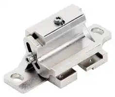


F39-LGA
MOUNTING BRACKET, SAFETY LIGHT CURTAIN
- Manufacturer: OMRON INDUSTRIAL AUTOMATION
- Product type:
- SVHC: To Be Advised
- For Use With: Omron F3SG-R Series Safety Light Curtains
| Delivery and price | |
|---|---|
| Units per pack | 1 |
| Price | 33.8 € |
| Current stock | 10+ |
| Lead time | 30 days |
## **Safety Light Curtain F3SG-RA**

## **Advanced Safety Light Curtain in Rugged, IP67 Rated Housing**

- Rugged, IP67 rated housing resists washdown

- Space-saving slim profile of 35x35 mm (1.37 in.)

- Scan QR code with smart phone for local language support and troubleshooting guide

- Built-in muting; requires no external muting controller

- All models designed for global use. PNP/NPN output selection by DIP switch

- Resolution: 14 mm (finger protection) and 30 mm (hand and arm protection) models

- Cascaded designs possible: 3 segments, up to 255 beams

- “Smart click” 1/8 turn quick connect M12 cables: for fast installation and proper torque to ensure IP67 connection

- 14mm resolution up to 10.0 m (32 ft.) range in 160 to 2080 mm (6.3 to 81.9 inch) protective heights

- 30mm resolution up to 20.0 m (65 ft.) range in 190 to 2510 mm (7.3 to 98.7 inch) protective heights

## **Online Multilanguage Support Built-in Muting and Blanking**

To acces **s** troublesho **o** ting support **f** or safety light curt **a** in errors in y **o** ur local lan **g** uage use your tabl **e** t or smartph **o** ne to scan **a** QR code sticker th **a** t can be ap **p** lied to the m **a** chine.

Buil **t** -in muting to pass throug **h** materials in **t** o the haz **a** rd zone req **u** ires no external muting controller. The bl **a** nking functi **o** n disables spe **c** ific beams o **f** the safety li **g** ht curtain. A war **n** ing zone ca **n** be set to al **e** rt people be **f** ore they enter a dan **g** er zone usin **g** single or s **e** riescon **n** ected units **w** hen horizon **t** ally mounte **d** .

## **Reduced Wiring Work**

Also acc **e** ssible by co **m** puter, oper **a** tors can check th **e** error details in 8 languag **e** s and download manuals fro **m** a dedicate **d** website.

The inter **a** ctive diagno **s** tics ask abo **u** t error indicator **c** olor, indicat **o** r flashing frequency and DIP switch settings to **t** horoughly a **n** alyze the cause of **a** n error.

Languag **e** s include En **g** lish, Spanis **h** , French, Chinese, Korean, Jap **a** nese, Germ **a** n, and Italian.

“Sm **a** rt click” 1/8 **t** urn quick-co **n** nect M12 c **a** bles allo **w** fast installa **t** ion and pro **p** er torque to ens **u** re IP67 con **n** ection.

**1**

**F3SG-RA**

## **Ordering Information**

## **Main Units**

## **Safety Light Curtain**

## **Finger protection**

|**Model**|**Number of beams**|**Protective height**<br>**(mm)**|
|---|---|---|
|**F3SG-4RA0160-14**|15|160|
|**F3SG-4RA0240-14**|23|240|
|**F3SG-4RA0320-14**|31|320|
|**F3SG-4RA0400-14**|39|400|
|**F3SG-4RA0480-14**|47|480|
|**F3SG-4RA0560-14**|55|560|
|**F3SG-4RA0640-14**|63|640|
|**F3SG-4RA0720-14**|71|720|
|**F3SG-4RA0800-14**|79|800|
|**F3SG-4RA0880-14**|87|880|
|**F3SG-4RA0960-14**|95|960|
|**F3SG-4RA1040-14**|103|1,040|
|**F3SG-4RA1120-14**|111|1,120|
|**F3SG-4RA1200-14**|119|1,200|
|**F3SG-4RA1280-14**|127|1,280|
|**F3SG-4RA1360-14**|135|1,360|
|**F3SG-4RA1440-14**|143|1,440|
|**F3SG-4RA1520-14**|151|1,520|
|**F3SG-4RA1600-14**|159|1,600|
|**F3SG-4RA1680-14**|167|1,680|
|**F3SG-4RA1760-14**|175|1,760|
|**F3SG-4RA1840-14**|183|1,840|
|**F3SG-4RA1920-14**|191|1,920|
|**F3SG-4RA2000-14**|199|2,000|
|**F3SG-4RA2080-14**|207|2,080|


## **Hand and arm protection**

|**Model**|**Number of beams**|**Protective height**<br>**(mm)**|
|---|---|---|
|**F3SG-4RA0190-30**|8|190|
|**F3SG-4RA0270-30**|12|270|
|**F3SG-4RA0350-30**|16|350|
|**F3SG-4RA0430-30**|20|430|
|**F3SG-4RA0510-30**|24|510|
|**F3SG-4RA0590-30**|28|590|
|**F3SG-4RA0670-30**|32|670|
|**F3SG-4RA0750-30**|36|750|
|**F3SG-4RA0830-30**|40|830|
|**F3SG-4RA0910-30**|44|910|
|**F3SG-4RA0990-30**|48|990|
|**F3SG-4RA1070-30**|52|1,070|
|**F3SG-4RA1150-30**|56|1,150|
|**F3SG-4RA1230-30**|60|1,230|
|**F3SG-4RA1310-30**|64|1,310|
|**F3SG-4RA1390-30**|68|1,390|
|**F3SG-4RA1470-30**|72|1,470|
|**F3SG-4RA1550-30**|76|1,550|
|**F3SG-4RA1630-30**|80|1,630|
|**F3SG-4RA1710-30**|84|1,710|
|**F3SG-4RA1790-30**|88|1,790|
|**F3SG-4RA1870-30**|92|1,870|
|**F3SG-4RA1950-30**|96|1,950|
|**F3SG-4RA2030-30**|100|2,030|
|**F3SG-4RA2110-30**|104|2,110|
|**F3SG-4RA2190-30**|108|2,190|
|**F3SG-4RA2270-30**|112|2,270|
|**F3SG-4RA2350-30**|116|2,350|
|**F3SG-4RA2430-30**|120|2,430|
|**F3SG-4RA2510-30**|124|2,510|


**2**

**F3SG-RA**

## **Accessories (Sold separately)**

**Single-ended Connector Cable**

> **Appearance** ~~A~~ **Type Cable length Specifications Model** For emitter ~~|~~ 3 m7 m 1 2 12 +24 VDCTEST BrownBlack **F39-JG3A-LF39-JG7A-L** M12 connector ~~sl~~ 10 m 6S 5 3 0 VDC Blue **F39-JG10A-L** (5-pin), 5 wires 4 3 4 Not used White 15 m 5 Not used Yellow **F39-JG15A-L** | Color: Gray ~~as)~~ Female ~~J~~ 20 m **F39-JG20A-L** 7€y ~~>~~ 3 m 1 RESET Yellow **F39-JG3A-D** ~~”~~ For receiverM12 connector (8-pin), 8 wires ~~CT~~ 10 m7 m ZEN 76 1 58 243 3425 MUTE A MUTE B+24 VDCOSSD 1 GrayPinkBrownBlack **F39-JG7A-DF39-JG10A-D** Color: Black 15 m 6 OSSD 2 White **F39-JG15A-D** Female 7 0 VDC Blue 20 m 8 AUX Red **F39-JG20A-D** ~~-—~~ **Double-ended Cable For cable extension and simple wiring**

|**Appearance**|**Type**<br>~~ey~~|**Cable length**<br>~~ey~~|**Specifications**<br>~~ey~~|**Model**|
|---|---|---|---|---|
|_<br>f|For emitter<br>M12 connector<br>(5-pin)<br>on both ends<br>Color: Gray|0.5 m<br>~~r~~|Brown<br>Blue<br>Black<br>White<br>Yellow<br>1<br>3<br>2<br>4<br>5<br>5<br>3<br>2<br>1<br>4<br>Brown<br>Blue<br>Black<br>White<br>Yellow<br>1<br>3<br>2<br>4<br>5<br>Female<br>5<br>4<br>1<br>2<br>3<br>Male<br>Connected to Power Cable<br>or Double-Ended Cable<br>Connected to Single-Ended Cable, or<br>Double-Ended cable<br>~~Ce~~<br>~~CHESS~~<br>~~FN~~|**F39-JGR5B-L**|
|||1 m<br>~~sl~~||**F39-JG1B-L**|
|||3 m<br>~~Ce~~<br>~~CH~~||**F39-JG3B-L**|
|||5 m<br>~~Ce~~<br>~~CH~~||**F39-JG5B-L**|
|||7 m<br>~~CH~~<br>~~FN~~||**F39-JG7B-L**|
|||10 m<br>~~CH~~<br>~~FN~~||**F39-JG10B-L**|
|||15 m<br>~~CH~~<br>~~FN~~||**F39-JG15B-L**|
|||20 m||**F39-JG20B-L**|
||For receiver<br>M12 connector<br>(8-pin)<br>on both ends<br>Color: Black|0.5 m<br>~~sl~~|Brown<br>Blue<br>Black<br>White<br>Yellow<br>Red<br>Gray<br>Pink<br>Blue<br>Black<br>White<br>Yellow<br>Red<br>Gray<br>Pink<br>2<br>7<br>5<br>6<br>1<br>8<br>3<br>4<br>Brown<br>5<br>8<br>4<br>3<br>2<br>1<br>7<br>6<br>5<br>8<br>6<br>7<br>1<br>2<br>3<br>4<br>2<br>7<br>5<br>6<br>1<br>8<br>3<br>4<br>Connected to Power Cable<br>or Double-Ended Cable<br>Connected to Single-Ended Cable, or<br>Double-Ended cable<br>Female<br>Male<br>—_<br>5<br>rx}<br>HJ<br>OA<br>~~—@~~E~~SSs=~~<br>~~——_~~e ~~ao~~<br>FE} <<<br>4|**F39-JGR5B-D**|
|||1 m<br>~~sl~~<br>~~—@~~||**F39-JG1B-D**|
|||3 m<br>~~sl~~<br>~~—@~~||**F39-JG3B-D**|
|||5 m<br>~~—@~~||**F39-JG5B-D**|
|||7 m<br>~~—@~~<br>~~——_~~||**F39-JG7B-D**|
|||10 m<br>~~—@~~<br>~~——_~~<br>~~|~~||**F39-JG10B-D**|
|||15 m<br>~~——_~~<br>~~|~~||**F39-JG15B-D**|
|||20 m<br>~~|~~||**F39-JG20B-D**|


**Y-Joint Plug/Socket Connector for Advance type F3SG-RA**

**==> picture [467 x 140] intentionally omitted <==**

**----- Start of picture text -----**<br>
Appearance a Type Cable length Specifications Model<br>F3SG-RA F3SG-RA<br>Emitter Receiver<br>M12 connectors.<br>Used for reduced 0.5 m : F39-GCNY2<br>Y-Joint Plug/<br>wiring. Socket Connector for Advance<br>F39-GCNY2<br>Double-ended Cable<br>F39-JG@B-L(Gray)<br>Single-ended Connector<br>Cable<br>F39-JG@A-D(Black)<br>**----- End of picture text -----**<br>


**Cascading Cable (Two cables per set, for emitter and receiver)**

**==> picture [468 x 123] intentionally omitted <==**

**----- Start of picture text -----**<br>
Appearance a Type Cable length Specifications Model<br>Secondary  Secondary<br>sensor 1  sensor 1<br>(Emitter) (Receiver)<br>Emitter cable:<br>Cap (5-pin), M12  Cascading Cable<br>connector (5-pin) 0.2 m F39-JGR2W F39-JGR2W<br>Receiver cable: Primary  Primary<br>Cap (8-pin), M12  sensor (Emitter) sensor (Receiver)<br>connector (8-pin)<br>Cable Cable<br>F39-JG@@@-D F39-JG@@@-L<br>**----- End of picture text -----**<br>


**3**

**F3SG-RA**

## **Sensor Mounting Brackets**

|**Appearance**|**Specification**|**Application**|**Model**|
|---|---|---|---|
|Me a|Standard Fixed<br>Bracket|Bracket to mount the F3SG-R.<br>Side mounting and backside mounting possible.<br>(Included in the F3SG-R product package. See *1 below<br>for the number of included brackets.)|**F39-LGF**|
|Fe|Standard<br>Adjustable<br>Bracket|Bracket to mount the F3SG-R.<br>Beam alignment after mounting<br>possible.The angle adjustment range is±15°.<br>Side mounting and backside mounting possible.<br>(Sold separately. See*1below for the number of required brackets.)|**F39-LGA**|
||Top/Bottom<br>Adjustable Bracket *2|Bracket to mount the F3SG-R. Use this bracket at the<br>top and bottom positions of the F3SG-R.<br>Beam alignment after mounting possible.<br>The angle adjustment range is±22.5°.<br>Side mounting and backside mounting possible.<br>(Sold separately. 4 brackets per set.)|**F39-LGTB**|
||Top/Bottom<br>Adjustable Bracket *2<br>(For user-made<br>mounting part)|Top/Bottom Adjustable Bracket without a bracket to<br>mount to the wall. Use the user's own wall mounting part<br>to suit the machine.<br>(Sold separately. 4 brackets per set.)|**F39-LGTB-1**|


- *1 Two brackets per set

   - [for F3SG-@RA@@@@-14]

   - Protective height of 0160 to 1200: 2 sets,  Protective height of 1280 to 2080: 3 sets

   - [for F3SG-@RA@@@@-30]

   - Protective height of 0190 to 1230: 2 sets,  Protective height of 1310 to 2270: 3 sets, Protective height of 2350 to 2510: 4 sets

- *2 Top/Bottom Adjustable Bracket cannot be used with the Standard Fixed Bracket. Use with the Standard Adjustable Bracket. (See *1 for the number of required brackets.)

## **Interface units and configuration tool SD Manager 2**

|||**Appearance**|**Type**|**Specifications**|**Model**|
|---|---|---|---|---|---|
|||||The Configuration Tool SD Manager 2 is available to||
|||||download from our website at||
||||SD Manager2|http://www.omron247.com/safety_light_curtain/<br>f3sg_ra/Software tools/SD Manager 2 Configurator.|−|
|||||To change the settings of the F3SG-RA using SD||
|||||Manager 2, it is necessary to set the receiver's two||
|||||DIP switches No. 8 to ON.||
||||Interface Unit|F39-GIF interface unit to connect the F3SG-RA<br>receiver to a USB port of the PC|**F39-GIF**|
|||a|Bluetooth unit|F39-BT bluetooth unit to enable bluetooth on the<br>F3SG-RA|**F39-BT**|
||**Lamp**|||||
|**End Cap**<br>**Appearance**<br>**Type**<br>**Specifications**<br>**Model**<br>Lamp unit<br>The lamp unit can be connected to a receiver and<br>turned ON based on the operation of F3SG-RA.<br>The lamp can indicate red, orange, and green colors,<br>to which three different states can be assigned.<br>**F39-LP**<br>Bluetooth + Lamp unit<br>**F39-BTLP**<br>**Appearance**<br>**Specifications**<br>**Model**<br>Housing color: Black<br>For both emitter and receiver<br>(Attached to the F3SG-R. The End Cap can be purchased if lost.)<br>**F39-CNM**<br>~~i.ee~~||||||
|»»|»»|omRON||||
|**4**<br>»»|»»|omRON||||


**F3SG-RA**

## **Spatter Protection Cover(Two covers per set, for emitter and receiver)**

## Spatter Protection Covers include mounting brackets.

For Safety Light Curtain models of the protective height of 2,000 mm or longer, use two Spatter Protection Covers of different lengths.

|**Appearance**|**Safety Light Curtain Model**|**Safety Light Curtain Model**|**Model**|
|---|---|---|---|
||**Finger protection**|**Hand and arm protection**||
||**F3SG-**@**RA0160-14**|**F3SG-**@**RA0190-30**|**F39-HGA0200**|
||**F3SG-**@**RA0240-14**|**F3SG-**@**RA0270-30**|**F39-HGA0280**|
||**F3SG-**@**RA0320-14**|**F3SG-**@**RA0350-30**|**F39-HGA0360**|
||**F3SG-**@**RA0400-14**|**F3SG-**@**RA0430-30**|**F39-HGA0440**|
||**F3SG-**@**RA0480-14**|**F3SG-**@**RA0510-30**|**F39-HGA0520**|
||**F3SG-**@**RA0560-14**|**F3SG-**@**RA0590-30**|**F39-HGA0600**|
||**F3SG-**@**RA0640-14**|**F3SG-**@**RA0670-30**|**F39-HGA0680**|
||**F3SG-**@**RA0720-14**|**F3SG-**@**RA0750-30**|**F39-HGA0760**|
||**F3SG-**@**RA0800-14**|**F3SG-**@**RA0830-30**|**F39-HGA0840**|
||**F3SG-**@**RA0880-14**|**F3SG-**@**RA0910-30**|**F39-HGA0920**|
||**F3SG-**@**RA0960-14**|**F3SG-**@**RA0990-30**|**F39-HGA1000**|
||**F3SG-**@**RA1040-14**|**F3SG-**@**RA1070-30**|**F39-HGA1080**|
||**F3SG-**@**RA1120-14**|**F3SG-**@**RA1150-30**|**F39-HGA1160**|
||**F3SG-**@**RA1200-14**|**F3SG-**@**RA1230-30**|**F39-HGA1240**|
||**F3SG-**@**RA1280-14**|**F3SG-**@**RA1310-30**|**F39-HGA1320**|
||**F3SG-**@**RA1360-14**|**F3SG-**@**RA1390-30**|**F39-HGA1400**|
||**F3SG-**@**RA1440-14**|**F3SG-**@**RA1470-30**|**F39-HGA1480**|
||**F3SG-**@**RA1520-14**|**F3SG-**@**RA1550-30**|**F39-HGA1560**|
||**F3SG-**@**RA1600-14**|**F3SG-**@**RA1630-30**|**F39-HGA1640**|
||**F3SG-**@**RA1680-14**|**F3SG-**@**RA1710-30**|**F39-HGA1720**|
||**F3SG-**@**RA1760-14**|**F3SG-**@**RA1790-30**|**F39-HGA1800**|
||**F3SG-**@**RA1840-14**<br>~~——~~|**F3SG-**@**RA1870-30**<br>~~——~~|**F39-HGA1880**|
||**F3SG-**@**RA1920-14**<br>~~——~~|**F3SG-**@**RA1950-30**<br>~~——~~|**F39-HGA1960**|
||**F3SG-**@**RA2000-14**|**F3SG-**@**RA2030-30**|**F39-HGA1480**|
||||**F39-HGA0550**|
||**F3SG-**@**RA2080-14**<br>~~re~~|**F3SG-**@**RA2110-30**<br>~~re~~|**F39-HGA1560**|
||||**F39-HGA0550**|
||−<br>~~re~~|**F3SG-**@**RA2190-30**<br>~~re~~|**F39-HGA1640**|
||||**F39-HGA0550**|
||−<br>~~re~~|**F3SG-**@**RA2270-30**<br>~~re~~|**F39-HGA1720**|
||||**F39-HGA0550**|
||−<br>~~re~~<br>~~re~~|**F3SG-**@**RA2350-30**<br>~~re~~<br>~~re~~|**F39-HGA1800**|
||||**F39-HGA0550**|
||−<br>~~re~~<br>~~a~~|**F3SG-**@**RA2430-30**<br>~~re~~<br>~~a~~|**F39-HGA1880**|
||||**F39-HGA0550**|
||−<br>~~ee~~|**F3SG-**@**RA2510-30**<br>~~ee~~|**F39-HGA1960**|
||||**F39-HGA0550**|


## **Test Rod**

|**Diameter**|**Model**|
|---|---|
|14 mm dia.|**STI-TO14**|
|30 mm dia.|**STI-TO30**|


**5** omRONn ~~a~~

**F3SG-RA**

**Ratings and Specifications**

## **Main unit**

||||**F3SG-4RA**����**-14**|**F3SG-4RA**����**-14**|**F3SG-4RA**����**-30**|
|---|---|---|---|---|---|
|**Type of ESPE (IEC 61496-1)**||**Type 4**|F3SG-4RA����-14/-30|||
|||||||
|**Performance**|**Object Resolution**<br>**(Detection Capability)**||Opaque objects|||
||||14-mm dia.||30-mm dia.|
||**Beam Gap**||10 mm||20 mm|
||**Number of Beams**||15 to 207||8 to 124|
||**Lens Size**||5.2 × 3.4(W × H)mm||7-mm dia.|
||**Protective Height**||160 to 2080 mm(6.3 to 81.9 inch)||190 to 2510 mm(7.3 to 98.7 inch)|
||**Operating Range**|**Long**|0.3 to 10.0 m(1 to 32 ft.)||0.3 to 20.0 m(1 to 65 ft.)|
|||**Short**|0.3 to 3.0 m(1 to 10 ft.)||0.3 to 7.0 m(1 to 23 ft.)|
||**Response Time**|**ON to OFF**|Normal mode: 8 to 18 ms max. *1<br>Slow mode: 16 to 36 ms max. *1 *2|||
|||**OFF to ON**|40 to 90 ms max. *1|||
|||*1 Response time when used in one segment system or in cascaded connection.<br>Refer to page 8.<br>*2 Selectable byConfiguration Tool.||||
||**Effective Aperture Angle**<br>**(EAA) (IEC 61496-2)**|**Type 4**|±2.5° max., emitter and receiver at operating range of 3 m or greater|||
|||||||
||**Light Source**||Infrared LEDs, Wavelength: 870 nm|||
||**Startup Waiting Time**||2 s max.|||
|**Electrical**|**Power Supply Voltage (Vs)**||SELV/PELV 24 VDC±20%(ripplep-p10% max.)|||
||**Current Consumption**|||Refer topage 8 .||
||**Safety Outputs (OSSD)**||Two PNP or NPN transistor outputs (PNP or NPN is selectable by DIP Switch.)<br>Load current of 300 mA max., Residual voltage of 2 V max. (except for voltage drop due to cable<br>extension), Capacitive load  of 1μF max., Inductive load  of 2.2 H max. *1<br>Leakage current of 1 mA max. (PNP), 2 mA max. (NPN) *2<br>*1<br>The load inductance is the maximum value when the safety output frequently repeats ON and<br>OFF. When you use the safety output at 4 Hz or less, the usable load inductance becomes<br>larger.<br>*2<br>These values must be taken into consideration when connecting elements including a<br>capacitive load such as a capacitor.|||
||**Auxiliary Output**||One PNP or NPN transistor output (PNP or NPN is selectable by DIP Switch.)<br>Load current of 100 mA max., Residual voltage  of 2 V max .|||
||**Output Operation**<br>**Mode**|**Safety Output**|Light-ON(Safetyoutput is enabled when the receiver receives an emittingsignal.)|||
|||**Auxiliary Output**|Mutingor Override output(default) (Configurable byConfiguration Tool)|||
||**Input Voltage**|**ON Voltage**|TEST:<br>24 V Active: 9 V to Vs (sink current 3 mA max.) *<br>0 V Active: 0 to 3 V (source current 3 mA max.)<br>MUTE A/B:<br>PNP: Vs to Vs-3 V (sink current 3 mA max.) *<br>NPN: 0 to 3 V (source current 3 mA max.)<br>RESET:<br>PNP: Vs to Vs-3 V (sink current 5 mA max.) *<br>NPN: 0 to 3 V(source current 5 mA max.)|||
|||**OFF Voltage**|TEST:<br>24 V Active : 0 to 1.5 V or open<br>0 V Active :  9 V to Vs or open<br>MUTE A/B, RESET:<br>PNP: 0 to 1/2 Vs, or open *<br>NPN: 1/2 Vs to Vs, or open *|||
|||* The Vs indicates a supplyvoltage value inyour environment.||||
||**Overvoltage Category (IEC 60664-1)**||II|||
||**Indicators**|||Refer topage10.||
||**Protective Circuit**||Output shortprotection, Power supplyreversepolarity protection|||
||**Insulation Resistance**||20 MΩor higher(500 VDC megger)|||
||**Dielectric Strength**||1,000 VAC, 50/60 Hz(1 min)|||
|**Functional**|**Mutual Interference Prevention(Scan Code)**||This functionprevents mutual interference in upto two F3SG-RA systems.|||
||**Cascade Connection**||Number of cascaded segments: 3 max.<br>Total number of beams: 255 max.<br>Cable lengths between sensors: 10 m max.|||
||**Test Function**||Self-test (at power-on, and during operation)<br>External test(light emission stopfunction bytest input)|||
||**Safety-Related Functions**||Interlock<br>External device monitoring (EDM)<br>Pre-reset<br>Fixed blanking/Floating blanking<br>Reduced resolution<br>Muting/Override<br>Scan code selection<br>PNP/NPN selection<br>Response time adjustment|||


**6**

**F3SG-RA**

||||**F3SG-4RA**����**-14**|**F3SG-4RA**����**-14**|**F3SG-4RA**����**-30**|
|---|---|---|---|---|---|
|**Environ-**<br>**mental**|**Ambient Temperature**|**Operating**|-10 to 55°C(14 to 131°F) (non-icing)|||
|||**Storage**|-25 to 70°C(-13 to 158°F)|||
||**Ambient Humidity**|**Operating**|35% to 85%(non-condensing)|||
|||**Storage**|35% to 95%|||
||**Ambient Illuminance**||Incandescent lamp: 3,000 Ix max. on receiver surface<br>Sunlight: 10,000 Ix max. on receiver surface|||
||**Degree of Protection(IEC 60529)**||IP65 and IP67|||
||**Vibration Resistance(IEC 61496-1)**||10 to 55 Hz, Multiple amplitude of 0.7 mm, 20 sweeps for all 3 axes|||
||**Shock Resistance(IEC 61496-1)**||100 m/s2, 1000 shocks for all 3 axes|||
||**Pollution Degree(IEC 60664-1)**||Pollution Degree 3|||
|**Connec-**<br>**tions**|**Power cable**|**Type of Connection**|M12 connectors: 5-pin emitter and 8-pin receiver, IP67 rated when mated, Cablesprewired to the sensors|||
|||**Number of Wires**|Emitter: 5, Receiver: 8|||
|||**Cable Length**|0.3 m|||
|||**Cable Diameter**|6 mm|||
|||**Minimum Bending**<br>**Radius**|R5 mm|||
||**Cascading cable**|**Type of Connection**|M12 connectors: 5-pin emitter and 8-pin receiver, IP67 rated when mated|||
|||**Number of Wires**|Emitter: 5, Receiver: 8|||
|||**Cable Length**|0.2 m|||
|||**Cable Diameter**|6 mm|||
|||**Minimum Bending**<br>**Radius**|R5 mm|||
||**Extension cable**<br>**- Single-ended cable**<br>**- Double-ended cable**|**Type of Connection**|M12 connectors: 5-pin emitter and 8-pin receiver, IP67 rated when mated|||
|||**Number of Wires**|Emitter: 5, Receiver: 8|||
|||**Cable Length**||Refer topage 3.||
|||**Cable Diameter**|6.6 mm|||
|||**Minimum Bending**<br>**Radius**|R36 mm|||
||**Extension of Power Cable**||100 m max.|||
|**Material**|**Material**||Housing: Aluminum<br>Cap: PBT<br>Front window: PMMA<br>Cable: Oil resistant PVC<br>Mounting Bracket: ZDC2<br>FEplate: SUS|||
||**Weight(packaged)**|||Refer topage 8.||
||**Included Accessories**||Safety Precautions, Quick Installation Manual, Standard Fixed Bracket*, Troubleshooting Guide<br>Sticker, Warning Zone Label<br>* The quantity of Standard Fixed Brackets included varies depending on the protective height.<br>[F3SG-�RA����-14]<br>- Protective height of 0160 to 1200: 2 sets<br>- Protective height of 1280 to 2080: 3 sets<br>[F3SG-�RA����-30]<br>- Protective height of 0190 to 1230: 2 sets<br>- Protective height of 1310 to 2270: 3 sets<br>- Protective height of 2350 to 2510: 4 sets|||
|**Conformity**|**Conforming standards**|||Refer topage 19.||
||**Type of ESPE (IEC 61496-1)**||Type 4|||
||**Performance Level**<br>**(PL)/Safety category**|**Type 4**|PL e/Category 4 (EN ISO 13849-1:2008)|||
|||||||
||**PFHd**||1.1 × 10⁻⁸ (IEC 61508)|||
||**Proof test interval TM**||Every20years(IEC 61508)|||
||**SFF**||99%(IEC 61508)|||
||**HFT**||1(IEC 61508)|||
||**Classification**||Type B(IEC 61508-2)|||


**7**

**F3SG-RA**

## **List of Models/Response Time/Current Consumption/Weight**

## **F3SG-4RA** ���� **-14**

|**Model**|**Number of**<br>**Beams**|**Protective**<br>**Height**<br>**[mm]**|**Response Time [ms]**|**Response Time [ms]**|**Response Time [ms]**|**Current**<br>**Consumption[mA]**|**Current**<br>**Consumption[mA]**|**Weight**<br>**[kg]*2**|
|---|---|---|---|---|---|---|---|---|
||||**ON**→<br>**OFF*1**|**OFF**<br>**(Synchronized)**<br>→**ON**|**OFF**<br>**(Not synchronized)**<br>→**ON**|**Emitter**|**Receiver**||
|**F3SG-4RA0160-14**|15|160|8|40|140|40|75|1.8|
|**F3SG-4RA0240-14**|23|240|8|40|140|45|75|2.0|
|**F3SG-4RA0320-14**|31|320|8|40|140|55|75|2.2|
|**F3SG-4RA0400-14**|39|400|8|40|140|60|80|2.7|
|**F3SG-4RA0480-14**|47|480|13|65|165|50|80|2.9|
|**F3SG-4RA0560-14**|55|560|13|65|165|55|80|3.1|
|**F3SG-4RA0640-14**|63|640|13|65|165|60|85|3.3|
|**F3SG-4RA0720-14**|71|720|13|65|165|65|85|3.9|
|**F3SG-4RA0800-14**|79|800|13|65|165|65|90|4.1|
|**F3SG-4RA0880-14**|87|880|13|65|165|70|90|4.3|
|**F3SG-4RA0960-14**|95|960|13|65|165|75|90|4.5|
|**F3SG-4RA1040-14**|103|1040|13|65|165|80|95|4.7|
|**F3SG-4RA1120-14**|111|1120|13|65|165|85|95|4.8|
|**F3SG-4RA1200-14**|119|1200|13|65|165|90|100|5.0|
|**F3SG-4RA1280-14**|127|1280|13|65|165|95|100|5.2|
|**F3SG-4RA1360-14**|135|1360|13|65|165|95|105|5.6|
|**F3SG-4RA1440-14**|143|1440|18|90|190|85|105|5.8|
|**F3SG-4RA1520-14**|151|1520|18|90|190|90|105|6.0|
|**F3SG-4RA1600-14**|159|1600|18|90|190|90|110|6.6|
|**F3SG-4RA1680-14**|167|1680|18|90|190|95|110|6.8|
|**F3SG-4RA1760-14**|175|1760|18|90|190|100|115|7.0|
|**F3SG-4RA1840-14**|183|1840|18|90|190|100|115|7.2|
|**F3SG-4RA1920-14**|191|1920|18|90|190|105|120|7.3|
|**F3SG-4RA2000-14**|199|2000|18|90|190|105|120|7.5|
|**F3SG-4RA2080-14**|207|2080|18|90|190|110|125|8.1|


- *1 The response times are values when Scan Code is set at Code B. The response times for Code A are 1 ms shorter than these values.

- *2 The weight includes an emitter, a receiver and included brackets in a product package.

## **F3SG-4RA** ���� **-30**

|**Model**|**Number of**<br>**Beams**|**Protective**<br>**Height**<br>**[mm]**|**Response Time [ms]**|**Response Time [ms]**|**Response Time [ms]**|**Current**<br>**Consumption[mA]**|**Current**<br>**Consumption[mA]**|**Weight**<br>**[kg]*2**|
|---|---|---|---|---|---|---|---|---|
||||**ON**→<br>**OFF*1**|**OFF**<br>**(Synchronized)**<br>→**ON**|**OFF**<br>**(Not synchronized)**<br>→**ON**|**Emitter**|**Receiver**||
|**F3SG-4RA0190-30**|8|190|8|40|140|35|75|1.8|
|**F3SG-4RA0270-30**|12|270|8|40|140|35|75|2.0|
|**F3SG-4RA0350-30**|16|350|8|40|140|40|75|2.2|
|**F3SG-4RA0430-30**|20|430|8|40|140|45|75|2.7|
|**F3SG-4RA0510-30**|24|510|8|40|140|50|75|2.9|
|**F3SG-4RA0590-30**|28|590|8|40|140|50|75|3.1|
|**F3SG-4RA0670-30**|32|670|8|40|140|55|75|3.3|
|**F3SG-4RA0750-30**|36|750|8|40|140|60|80|3.9|
|**F3SG-4RA0830-30**|40|830|8|40|140|65|80|4.0|
|**F3SG-4RA0910-30**|44|910|13|65|165|50|80|4.2|
|**F3SG-4RA0990-30**|48|990|13|65|165|50|80|4.4|
|**F3SG-4RA1070-30**|52|1070|13|65|165|55|80|4.6|
|**F3SG-4RA1150-30**|56|1150|13|65|165|55|85|4.8|
|**F3SG-4RA1230-30**|60|1230|13|65|165|55|85|4.9|
|**F3SG-4RA1310-30**|64|1310|13|65|165|60|85|5.1|
|**F3SG-4RA1390-30**|68|1390|13|65|165|60|85|5.6|
|**F3SG-4RA1470-30**|72|1470|13|65|165|65|85|5.8|
|**F3SG-4RA1550-30**|76|1550|13|65|165|65|90|6.0|
|**F3SG-4RA1630-30**|80|1630|13|65|165|70|90|6.5|
|**F3SG-4RA1710-30**|84|1710|13|65|165|70|90|6.7|
|**F3SG-4RA1790-30**|88|1790|13|65|165|70|90|6.9|
|**F3SG-4RA1870-30**|92|1870|13|65|165|75|90|7.1|
|**F3SG-4RA1950-30**|96|1950|13|65|165|75|95|7.3|
|**F3SG-4RA2030-30**|100|2030|13|65|165|80|95|7.4|
|**F3SG-4RA2110-30**|104|2110|13|65|165|80|95|8.0|
|**F3SG-4RA2190-30**|108|2190|13|65|165|85|95|8.2|
|**F3SG-4RA2270-30**|112|2270|13|65|165|85|100|8.4|
|**F3SG-4RA2350-30**|116|2350|13|65|165|85|100|8.8|
|**F3SG-4RA2430-30**|120|2430|13|65|165|90|100|8.9|
|**F3SG-4RA2510-30**|124|2510|13|65|165|90|100|9.1|


- *1 The response times are values when Scan Code is set at Code B. The response times for Code A are 1 ms shorter than these values. The maximum speed of movement of a test rod up to which the detection capability is maintained is 2.0 m/s.

- *2 The weight includes an emitter, a receiver and included brackets in a product package.

**8**

**F3SG-RA**

## **Legislation and Standards**

1. The F3SG-R does not receive type approval provided by Article 44-2 of the Industrial Safety and Health Act of Japan. When using the F3SG-R in Japan as a "safety system for pressing or shearing machines" prescribed in Article 42 of that law, the machine control system must receive type approval.

2. The F3SG-R is electro-sensitive protective equipment (ESPE) in accordance with European Union (EU) Machinery Directive Index Annex V, Item 2.

3. EC Declaration of Conformity

- OMRON declares that the F3SG-R is in conformity with the requirements of the following EC Directives: Machinery Directive 2006/42/EC

EMC Directive 2004/108/EC

4. Conforming Standards

- (1) European standards

   - EN61496-1 (Type 4 ESPE), EN 61496-2 (Type 4 AOPD), EN61508-1 through -4 (SIL 3 for Type 4), EN ISO 13849-1:2008 (PL e, Category 4 for Type 4 and PL c)

- (2) International standards

IEC61496-1 (Type 4 ESPE), IEC61496-2 (Type 4 AOPD), IEC61508-1 through -4 (SIL 3 for Type 4), ISO 13849-1:2006 (PL e, Category 4 for Type 4

5.

- (1) JIS standards

JIS B 9704-1 (Type 4 ESPE), JIS B 9704-2 (Type 4 AOPD)

- (2) North American standards

UL61496-1(Type 4 ESPE), UL61496-2(Type 4 AOPD), UL508, UL1998, CAN/CSA C22.2 No.14, CAN/CSA C22.2 No.0.8

- (3) Chinese standards

GB4584(Specification of active opto-electronic protective devices for presses)

6. Third-Party Certifications

- (1) TÜV SÜD

   - EC Type-Examination certificate:

EU Machinery Directive, Type 4 ESPE (EN61496-1), Type 4 AOPD (EN 61496-2)

- Certificate:

Type 4 ESPE (EN61496-1), Type 4 AOPD (EN61496-2), EN 61508-1 through -4 (SIL 3 for Type 4), EN ISO 13849-1:2008 (PL e, Category 4 for Type 4, )

## (2) UL

   - UL Listing:

- Type 4  ESPE (UL61496-1), Type 4 AOPD (UL61496-2), UL508, UL1998, CAN/CSA C22.2 No.14, CAN/CSA C22.2 No.0.8

- (3) China National Casting and Forging Machines Quality Supervision and Inspection Center

   - Certificate:

GB4584 (Specification of active opto-electronic protective devices for presses)

7. Other Standards

The F3SG-R is designed according to the standards listed below. To make sure that the final system complies with the following standards and regulations, you are asked to design and use it in accordance with all other related standards, laws, and regulations. If you have any questions, consult with specialized organizations such as the body responsible for prescribing and/or enforcing machinery safety regulations in the location where the equipment is to be used.

- European Standards: EN415-4, EN691-1, EN692, EN693, IEC/TS 62046

- U.S. Occupational Safety and Health Standards: OSHA 29 CFR 1910.212

- U.S. Occupational Safety and Health Standards: OSHA 29 CFR 1910.217

- American National Standards: ANSI B11.1 to B11.19

- American National Standards: ANSI/RIA R15.06

- Canadian Standards Association CSA Z142, Z432, Z434

- SEMI Standards SEMI S2

- Japan Ministry of Health, Labour and Welfare "Guidelines for Comprehensive Safety Standards of Machinery", Standard Bureau's Notification No. 0731001 dated July 31, 2007.rms and Conditions Agreement

- Chinese National Standards: GB17120, GB27607

**9**

**F3SG-RA Indicator**

## **Emitter**

|**Name of Indicator**|**Name of Indicator**|**Color**|**Illuminated**|**Blinking**|
|---|---|---|---|---|
|Test|TEST|Green|−|External Test is being performed|
|Operating range|LONG|Green|Long range mode is selected|Lockout state due to DIP Switch setting error<br>or Operating range selection setting error|
|Power|POWER|Green|Power is ON.|Error due to noise|
|Lockout|LOCKOUT|Red|−|Lockout state due to error in emitter|


## **Receiver**

|**Name of Indicator**|**Name of Indicator**|**Color**|**Illuminated**|**Blinking**|
|---|---|---|---|---|
|Top-beam-state|TOP|Blue|The top beam is unblocked|Muting/Override state, or Lockout state due to Cap<br>error or Other sensor error|
|PNP/NPN mode|NPN|Green|NPN mode is selected by DIP Switch|−|
|Response time|SLOW|Green|Response Time Adjustment is enabled|−|
|Sequence error|SEQ|Yellow|−|Sequence error in Muting or Pre-reset mode|
|Blanking|BLANK|Green|Blanking, Warning Zone or Reduced Resolution is<br>enabled|Teach-in mode, or Blanking Monitoring error|
|Configuration|CFG|Green|−|Teach-in mode, zone measurement beng performed<br>by Dynamic Muting, or Lockout state due to<br>Parameter error or Cascading Configuration error|
|Interlock|INT-LK|Yellow|Interlock state|Pre-reset mode|
|External device<br>monitoring|EDM|Green|RESET input is in ON state|Lockout state due to EDM error|
|Internal error|INTERNAL|Red|−|Lockout state due to Internal error, or error due<br>to abnormal power supply or noise|
|Lockout|LOCKOUT|Red|−|Lockout state due to error in receiver|
|Stable-state|STB|Green|Incident light level is 170% or higher of  ON-threshold|Safety output is instantaneously turned OFF due to<br>ambient light or vibration|
|ON/OFF|ON/OFF|Green|Safety output is in ON state|−|
|||Red|Safety output is in OFF state, or the sensor is in<br>Setting state|Lockout state due to Safety Output error, or error due<br>to abnormal power supply or noise|
|Communication|COM|Green|Synchronization between emitter and receiver is<br>maintained|Lockout state due to Communication error, or error<br>due to abnormal power supply or noise|
|Bottom-beam-state|BTM|Blue|The bottom beam is unblocked|Muting/Override state, or Lockout state due to DIP<br>Switch setting error|


## **Interface Unit**

|**Interface Unit**||
|---|---|
|**Main unit**|PC/AT compatible machine (computer that runs Microsoft Windows)|
|**Operating system (OS)**|Windows 7 (32-bit/64-bit), Windows 8 (32-bit/64-bit)|
|**Communication port**|USB port×1|
|**Ambient temperature**|Operating: -10 to 55°C, Storage: -30 to 70°C(non-icing and non-condensing)|
|**Ambient humidity**|Operating: 35% to 85%, Storage: 35% to 95%(non-condensing)|


## **Lamp**

|**Item**|**F39-LP**|
|---|---|
|**Applicable Sensor**|F3SG-@RA Series Safety Light Curtain (Receiver)|
|**LED Light Color**|Red/Green/Orange|
|**Power Supply Voltage**|24 VDC±20%, ripple p-p 10% max.(shares sensor′s power supply)|
|**Current Consumption**|25 mA max. (shares sensor′s power supply.)|
|**Ambient Temperature**|Operating: -10 to 55°C, Storage: -25 to 70°C|
|**Ambient Humidity**|Operating: 35% to 85%, Storage: 35% to 95%|
|**Vibration Resistance**|10 to 55 Hz, Multiple amplitude of 0.7 mm,20 sweeps for all 3 axes|
|**Shock Resistance**|100 m/s2, 1000 shocks for all 3 axes|
|**Degree of Protection**|IP65 and IP67(When attached to F3SG)|
|**Type of Connection**|Connectable to F3SG-RA′s terminal connector|
|**Material**|Lighting element: PC, Other body parts: PBT|
|**Weight**|45 g (when packaged)|


**10**

**F3SG-RA**

## **Connections (Basic Wiring Diagram)**

## **Standalone F3SG-RA using PNP Outputs**

The following is the example of External Device Monitoring enabled, Manual Reset mode, PNP output and External Test in 24 V Active.

## **DIP Switch settings *2**

**==> picture [442 x 544] intentionally omitted <==**

**----- Start of picture text -----**<br>
Function DIP-SW1 DIP-SW2<br>EDM Enabled 2 ON 2 ON<br>3 ON 3 ON<br>Receiver Manual Reset<br>4 ON 4 ON<br>PNP (factory default setting) 7 ON 7 ON<br>Emitter External Test: 24 V Active (factory default setting) 4 ON<br>� : Indicates a switch position.<br>Configure functions with the DIP Switches before wiring.<br>Wiring Example<br>F39-JG@A-L F39-JG@A-D<br>S2 KM1 KM2<br>S1 KM1<br>KM2<br>KM1<br>KM2<br>M<br>+24 VDC<br>S1: Test Switch (Connect the line to 0 V  Functional Earth<br>Power Supply       if this switch is not required)<br>0 VDC S2: Lockout/Interlock Reset Switch<br>KM1, KM2: Safety relay with forcibly guided contacts (G7SA)<br>or magnetic contactor<br>M: 3-phase motor<br>*1.Also used as EDM input line.<br>*2.The functions are configurable with DIP Switch. Refer to<br>Safety Light Curtain F3SG-R Series User's Manual  for more<br>information on setting the functions by the DIP Switch.<br>Unblocked<br>Beam state Blocked<br>Test Switch (S1)<br>Reset Switch (S2)<br>OSSD<br>Emitter Receiver<br>0 VDC : Blue Not used : White Not used : Yellow  TEST : Black 24 VDC : Brown 0 VDC : Blue RESET : Yellow *1 MUTE A : Gray MUTE B : Pink AUX : Red OSSD1 : Black OSSD2 : White 24 VDC : Brown<br>**----- End of picture text -----**<br>


**Note:** The wiring examples in later pages do not indicate functional earth. To use functional earth, wire an earth cable according to the example above. Refer to _Safety Light Curtain F3SG-R Series User's Manual_ for more information.

**11**

**F3SG-RA**

## **Standalone F3SG-RA using NPN Outputs**

The following is the example of External Device Monitoring enabled, Manual Reset mode, NPN output and External Test in 0 V Active.

## **DIP Switch settings *2**

**==> picture [427 x 555] intentionally omitted <==**

**----- Start of picture text -----**<br>
Function DIP-SW1 DIP-SW2<br>EDM Enabled 2 ON 2 ON<br>3 ON 3 ON<br>Receiver Manual Reset<br>4 ON 4 ON<br>NPN 7 ON 7 ON<br>Emitter External Test: 0 V Active 4 ON<br>� : Indicates a switch position.<br>Configure functions with the DIP Switches before wiring.<br>Wiring Example<br>F39-JG@A-L F39-JG@A-D<br>KM1 KM2<br>KM1<br>S2<br>S1 KM2<br>KM1<br>KM2<br>M<br>+24 VDC<br>S1: Test Switch (Connect the line to 24 V if this switch is not required)<br>Power Supply S2: Lockout/Interlock Reset Switch<br>KM1, KM2: Safety relay with forcibly guided contacts (G7SA)<br>0 VDC or magnetic contactor<br>M: 3-phase motor<br>*1.Also used as EDM input line.<br>*2.The functions are configurable with DIP Switch. Refer to<br>Safety Light Curtain F3SG-R Series User's Manual  for more<br>information on setting the functions by the DIP Switch.<br>Unblocked<br>Beam state Blocked<br>Test Switch (S1)<br>Reset Switch (S2)<br>OSSD<br>Emitter Receiver<br>0 VDC : Blue Not used : White Not used : Yellow TEST : Black 24 VDC : Brown 0 VDC : Blue RESET : Yellow *1 MUTE A : Gray MUTE B : Pink AUX : Red OSSD1 : Black OSSD2 : White 24 VDC : Brown<br>**----- End of picture text -----**<br>


**12**

**F3SG-RA**

## **Standard Muting Mode/Exit-Only Muting Mode using PNP Outputs**

The following is the example of External Device Monitoring disabled, Auto Reset mode, PNP output and External Test in 24 V Active.

## **DIP Switch settings *6**

||**Function**|**DIP-SW1**|**DIP-SW2**|
|---|---|---|---|
|Receiver|EDM Disabled (factory default setting)|2<br>ON|2<br>ON|
||Auto Reset (factory default setting)|3<br>ON|3<br>ON|
|||4<br>ON|4<br>ON|
||PNP (factory default setting)|7<br>ON|7<br>ON|
|Emitter|External Test: 24 V Active (factory default setting)|4<br>ON||


� : Indicates a switch position.

Configure functions with the DIP Switches before wiring.

## **Wiring Example**

**==> picture [423 x 373] intentionally omitted <==**

**----- Start of picture text -----**<br>
F39-JG@A-L F39-JG@A-D<br>ML<br>S2<br>S1 *2<br>+ 24 VDC<br>Power Supply<br>0  VDC<br>S1: Test Switch (Connect the line to 0 V if this switch  IN1 IN2<br>       is not required) Muting<br>S2: Lockout/Interlock Reset Switch, Actuator *5 Safety<br>Override Switch  Controller *3 *4<br>      or Override Cancel Switch<br>ML: Muting lamp<br>*1.Also used as Override input line.<br>*2.Make sure to connect an override cancel switch to the Reset Unblocked<br>Beam state<br>line when using the override function. Otherwise the override Blocked<br>state may not be released by the override cancel switch,<br>resulting in serious injury. Test Switch (S1)<br>*3.Refer to page 29 for more information.<br>*4.The safety controller and the F3SG-R must share the power MUTE A<br>supply or be connected to the common terminal of the power<br>supply.<br>*5.Refer to  Smart Muting Actuator F3W-MA Series User's Manual MUTE B<br>for more information.<br>*6.The functions are configurable with DIP Switch. Refer to OSSD<br>Safety Light Curtain F3SG-R Series User's Manual  for more<br>Emitter Receiver<br>y<br>0 VDC : Blue Not used : White Not used : Yellow TEST : Black 24 VDC : Brown 0 VDC : Blue RESET : Yellow *1 MUTE A : Gra MUTE B : Pink AUX : Red OSSD1 : Black OSSD2 : White 24 VDC : Brown<br>**----- End of picture text -----**<br>


- *6.The functions are configurable with DIP Switch. Refer to _Safety Light Curtain F3SG-R Series User's Manual_ for more information on setting the functions by the DIP Switch.

**13**

**F3SG-RA**

## **Standard Muting Mode/Exit-Only Muting Mode using NPN Outputs**

The following is the example of External Device Monitoring enabled, Auto Reset mode, NPN output and External Test in 0 V Active.

## **DIP Switch settings *3**

**==> picture [466 x 371] intentionally omitted <==**

**----- Start of picture text -----**<br>
Function DIP-SW1 DIP-SW2<br>EDM Enabled 2 ON 2 ON<br>3 ON 3 ON<br>Receiver Auto Reset (factory default setting)<br>4 ON 4 ON<br>NPN 7 ON 7 ON<br>Emitter External Test: 0 V Active 4 ON<br>� : Indicates a switch position.<br>Configure functions with the DIP Switches before wiring.<br>Wiring Example<br>F39-JG@A-L F39-JG@A-D<br>KM1<br>KM2<br>ML KM1 KM2<br>+ 24 VDC<br>S3 Power Supply M<br>S1 S2 S4 S5<br>*2 0  VDC<br>KM1<br>KM2<br>Emitter Receiver<br>0 VDC : Blue Not used : White Not used : Yellow TEST : Black 24 VDC : Brown 0 VDC : Blue RESET : Yellow *1 MUTE A : Gray MUTE B : Pink  AUX : Red OSSD1 : Black OSSD2 : White 24 VDC : Brown<br>**----- End of picture text -----**<br>


S1: Test Switch (Connect the line to 24 V if this switch is not required)

- S2: Override Cancel Switch

- S3: Lockout/Interlock Reset Switch or Override Switch

- S4, S5: Muting sensor

KM1, KM2: Safety relay with forcibly guided contacts (G7SA) or magnetic contactor

M: 3-phase motor

ML: Muting lamp

- *1.Also used as Override input line.

- *2.Make sure to connect an override cancel switch to the Reset line when using the override function. Otherwise the override state may not be released by the override cancel switch, resulting in serious injury.

- *3.The functions are configurable with DIP Switch. Refer to _Safety Light Curtain F3SG-R Series User's Manual_ for more information on setting the functions by the DIP Switch.

**==> picture [67 x 91] intentionally omitted <==**

**----- Start of picture text -----**<br>
Unblocked<br>Beam state<br>Blocked<br>Test Switch (S1)<br>MUTE A<br>MUTE B<br>OSSD<br>**----- End of picture text -----**<br>


**==> picture [139 x 90] intentionally omitted <==**

**14**

**F3SG-RA**

## **Standard Muting Mode/Exit-Only Muting Mode with two Muting Sensors using PNP Outputs**

The following is the example of External Device Monitoring disabled, Auto Reset mode, PNP output and External Test in 24 V Active.

## **DIP Switch settings *5**

||**Function**|**DIP-SW1**|**DIP-SW2**|
|---|---|---|---|
|Receiver|EDM Disabled (factory default setting)|2<br>ON|2<br>ON|
||Auto Reset (factory default setting)|3<br>ON|3<br>ON|
|||4<br>ON|4<br>ON|
||PNP (factory default setting)|7<br>ON|7<br>ON|
|Emitter|External Test: 24 V Active (factory default setting)|4<br>ON||


� : Indicates a switch position.

Configure functions with the DIP Switches before wiring.

## **Wiring Example**

**==> picture [305 x 324] intentionally omitted <==**

**----- Start of picture text -----**<br>
F39-JG@A-L F39-JG@A-D<br>ML<br>S1 S2<br>*2<br>IN1 IN2<br>Safety<br>Controller *3 *4<br>Muting  +24 VDC<br>Sensor<br>A1 (PNP  B1 Power Supply<br>output) 0  VDC<br>Reflector<br>Emitter Receiver<br>0 VDC : Blue Not used : White Not used : Yellow TEST : Black 24 VDC : Brown 0 VDC : Blue RESET : Yellow *1 MUTE A : Gray MUTE B : Pink AUX : Red OSSD1 : Black OSSD2 : White 24 VDC : Brown<br>**----- End of picture text -----**<br>


S1: Test Switch (Connect the line to 0 V if this switch is not required)

S2: Lockout/Interlock Reset Switch,Override Switch or Override Cancel Switch

ML: Muting lamp

A1, B1: Muting sensor

**==> picture [67 x 91] intentionally omitted <==**

**----- Start of picture text -----**<br>
Unblocked<br>Beam state<br>Blocked<br>Test Switch (S1)<br>MUTE A<br>MUTE B<br>OSSD<br>**----- End of picture text -----**<br>


**==> picture [139 x 90] intentionally omitted <==**

- *1.Also used as Override input line.

- *2.Make sure to connect an override cancel switch to the Reset line when using the override function. Otherwise the override state may not be released by the override cancel switch, resulting in serious injury.

- *3.Refer to  page 29 for more information.

- *4.The safety controller and the F3SG-R must share the power supply or be connected to the common terminal of the power supply.

- *5.The functions are configurable with DIP Switch. Refer to _Safety Light Curtain F3SG-R Series User's Manual_ for more information on setting the functions by the DIP Switch.

**15**

**F3SG-RA**

## **Standard Muting Mode/Exit-Only Muting Mode with two Muting Sensors using NPN Outputs**

The following is the example of External Device Monitoring enabled, Auto Reset mode, NPN output and External Test in 0 V Active.

## **DIP Switch settings *3**

**==> picture [461 x 657] intentionally omitted <==**

**----- Start of picture text -----**<br>
Function DIP-SW1 DIP-SW2<br>EDM Enabled 2 ON 2 ON<br>3 ON 3 ON<br>Receiver Auto Reset (factory default setting)<br>4 ON 4 ON<br>NPN 7 ON 7 ON<br>Emitter External Test: 0 V Active 4 ON<br>� : Indicates a switch position.<br>Configure functions with the DIP Switches before wiring.<br>Wiring Example<br>F39-JG@A-L F39-JG@A-D<br>ML KM1 KM2<br>S1 S2 S3<br>*2<br>KM1<br>KM2<br>KM1<br>KM2<br>M<br>+24 VDC<br>Muting<br>A1 Sensor  B1 Power Supply<br>(NPN<br>0 VDC<br>output)<br>Reflector<br>*1.Also used as Override input line.<br>S1: Test Switch (Connect the line to 24 V if this switch is  *2.Make sure to connect an override cancel switch to the Reset line<br>       not required) when using the override function. Otherwise the override state<br>S2: Override Cancel Switch may not be released by the override cancel switch, resulting in<br>S3: Lockout/Interlock Reset Switch or Override Switch serious injury.<br>KM1, KM2: Safety relay with forcibly guided contacts (G7SA)  *3.The functions are configurable with DIP Switch. Refer to  Safety<br>or magnetic contactor Light Curtain F3SG-R Series User's Manual  for more information<br>M: 3-phase motor on setting the functions by the DIP Switch.<br>ML: Muting lamp<br>A1, B1: Muting sensor<br>Unblocked<br>Beam state Blocked<br>Test Switch (S1)<br>MUTE A<br>MUTE B<br>OSSD<br>Emitter Receiver<br>y<br>0 VDC : Blue Not used : White Not used : Yellow TEST : Black 24 VDC : Brown 0 VDC : Blue RESET : Yellow *1 MUTE A : Gra MUTE B : Pink AUX : Red OSSD1 : Black OSSD2 : White 24 VDC : Brown<br>**----- End of picture text -----**<br>


**16**

**F3SG-RA**

## **Standard Muting Mode with four Muting Sensors using PNP Outputs**

The following is the example of External Device Monitoring disabled, Auto Reset mode, PNP output and External Test in 24 V Active.

## **DIP Switch settings *5**

**==> picture [440 x 539] intentionally omitted <==**

**----- Start of picture text -----**<br>
Function DIP-SW1 DIP-SW2<br>EDM Disabled (factory default setting) 2 ON 2 ON<br>3 ON 3 ON<br>Receiver Auto Reset (factory default setting)<br>4 ON 4 ON<br>PNP (factory default setting) 7 ON 7 ON<br>Emitter External Test: 24 V Active (factory default setting) 4 ON<br>� : Indicates a switch position.<br>Configure functions with the DIP Switches before wiring.<br>Wiring Example<br>F39-JG@A-L F39-JG@A-D<br>ML<br>S1 S2<br>*2<br>IN1 IN2<br>Safety<br>Controller *3 *4<br>B1 B2<br>Reflector<br>+24 VDC<br>Power Supply<br>Muting<br>Sensor  0  VDC<br>A1 A2<br>(PNP<br>output)<br>S1: Test Switch (Connect the line to 0 V if this<br>       switch is not required)<br>S2: Lockout/Interlock Reset Switch,<br>Override Switch or Override Cancel Switch<br>ML: Muting lamp<br>A1, A2, B1, B2: Muting sensor<br>Emitter Receiver<br>0 VDC : Blue Not used : White Not used : Yellow TEST : Black 24 VDC : Brown 0 VDC : Blue RESET : Yellow *1 MUTE A : Gray MUTE B : Pink AUX : Red OSSD1 : Black OSSD2 : White 24 VDC : Brown<br>F3SG<br>F3SG<br>**----- End of picture text -----**<br>


Configure functions with the DIP Switches before wiring.

- *1.Also used as Override input line.

- *2.Make sure to connect an override cancel switch to the Reset line when using

- the override function. Otherwise the override state may not be released by the override cancel switch, resulting in serious injury.

- *3.Refer to page 1 9 for more information.

- *4.The safety controller and the F3SG-R must share the power supply or be connected to the common terminal of the power supply.

- *5.The functions are configurable with DIP Switch. Refer to _Safety Light Curtain_

- _F3SG-R Series User's Manual_ for more information on setting the functions by the DIP Switch.

**==> picture [69 x 90] intentionally omitted <==**

**----- Start of picture text -----**<br>
Unblocked<br>Beam state<br>Blocked<br>Test Switch (S1)<br>MUTE A<br>MUTE B<br>OSSD<br>**----- End of picture text -----**<br>


**==> picture [140 x 90] intentionally omitted <==**

**17**

**F3SG-RA**

## **Standard Muting Mode with four Muting Sensors using NPN Outputs**

The following is the example of External Device Monitoring enabled, Auto Reset mode, NPN output and External Test in 0 V Active.

## **DIP Switch settings *3**

||**Function**|**DIP-SW1**|**DIP-SW2**|
|---|---|---|---|
|Receiver|EDM Enabled|2<br>ON|2<br>ON|
||Auto Reset (factory default setting)|3<br>ON|3<br>ON|
|||4<br>ON|4<br>ON|
||NPN|7<br>ON|7<br>ON|
|Emitter|External Test: 0 V Active|4<br>ON||


� : Indicates a switch position.

Configure functions with the DIP Switches before wiring.

## **Wiring Example**

**==> picture [465 x 522] intentionally omitted <==**

**----- Start of picture text -----**<br>
F39-JG@A-L F39-JG@A-D<br>ML KM1 KM2<br>S1 S2 S3<br>*2<br>KM1<br>KM2<br>KM1<br>KM2<br>M<br>Reflector B1 B2 +24 VDC<br>Power Supply<br>0 VDC<br>Muting<br>Sensor  S1: Test Switch (Connect the line to 24 V if this switch is<br>A1 A2        not required)<br>(NPN<br>S2: Override Cancel Switch<br>output) S3: Lockout/Interlock Reset Switch or Override Switch<br>KM1, KM2: Safety relay with forcibly guided contacts (G7SA)<br>or magnetic contactor<br>M: 3-phase motor<br>ML: Muting lamp<br>A1, A2, B1, B2: Muting sensor<br>*1.Also used as Override input line. Unblocked<br>Beam state<br>*2.Make sure to connect an override cancel switch to the Reset line when Blocked<br>using the override function. Otherwise the override state maynot be<br>released by the override cancel switch, resulting in serious injury. Test Switch (S1)<br>*3.The functions are configurable with DIP Switch. Refer to  Safety Light<br>Curtain F3SG-R Series User's Manual  for more information on setting<br>MUTE A<br>the functions by the DIP Switch.<br>MUTE B<br>OSSD<br>Emitter Receiver<br>0 VDC : Blue Not used : White Not used : Yellow TEST : Black 24 VDC : Brown 0 VDC : Blue RESET : Yellow *1 MUTE A : Gray MUTE B : Pink AUX : Red OSSD1 : Black OSSD2 : White 24 VDC : Brown<br>F3SG<br>F3SG<br>**----- End of picture text -----**<br>


**18**

**F3SG-RA**

## **Pre-Resest Mode using PNP Output**

The following is the example of External Device Monitoring disabled, Pre-Reset mode, PNP output and External Test in 24 V Active. **DIP Switch settings *4**

**==> picture [507 x 489] intentionally omitted <==**

**----- Start of picture text -----**<br>
Function DIP-SW1 DIP-SW2<br>EDM Disabled (factory default setting) 2 ON 2 ON<br>3 ON 3 ON<br>Receiver Pre-Reset<br>4 ON 4 ON<br>PNP (factory default setting) 7 ON 7 ON<br>Emitter External Test: 24 V Active (factory default setting) 4 ON<br>� : Indicates a switch position.<br>Configure functions with the DIP Switches before wiring.<br>Wiring Example<br>F39-JG@A-L F39-JG@A-D<br>S2 S3<br>S1<br>+24 VDC<br>Power Supply<br>0 VDC<br>S1: Test Switch (Connect the line to 0 V if this switch is<br>      not required) IN IN1 IN2<br>S2: Lockout/Interlock Reset Switch<br>PLC *3<br>S3: Pre-Reset Switch Safety<br>PLC: Programmable controller Controller *1 *2<br>       (Used for monitoring only. NOT related to safety system.)<br>*1.Refer to the following list "Connectable Safety Control Pre-Reset Switch (S3)<br>Units" on this page.<br>*2.The safety controller and the F3SG-R must share thepower supply or be connected to the common terminal Beam state UnblockedBlocked<br>of the power supply.<br>*3.When connecting to the PLC, the output mode must be Reset Switch (S2)<br>changed with the Configuration Tool.<br>*4.The functions are configurable with DIP Switch. Refer to OSSD<br>Safety Light Curtain F3SG-R Series User's Manual  for T1 T3<br>more information on setting the functions by the DIP T2<br>Switch.<br>T1: Push time: must be T1 >= 300ms<br>Emitter Receiver<br>y<br>0 VDC : Blue Not used : White Not used : Yellow TEST : Black 24 VDC : Brown 0 VDC : Blue RESET : Yellow PRE-RESET : Gra Not used : Pink AUX : Red OSSD1 : Black OSSD2 : White 24 VDC : Brown<br>**----- End of picture text -----**<br>


Configure functions with the DIP Switches before wiring.

T2: Pre-reset limit time between Pre-reset and Reset: must be T2 <= 60s

T3: Push time: must be T3 >= 300ms

## **Connectable Safety Control Units**

The F3SG-RA with PNP output can be connected to the safety control units listed in the table below.

|**Connectable Safety Control Units (PNP output)**|**Connectable Safety Control Units (PNP output)**|**Connectable Safety Control Units (PNP output)**|
|---|---|---|
|**G9SA-301**<br>**G9SA-321**<br>**G9SA-501**<br>**G9SB-200-B**<br>**G9SB-200-D**<br>**G9SB-301-B**<br>**G9SB-301-D**<br>**G9SE-201**<br>**G9SE-401**<br>**G9SE-221-T**@|**G9SX-AD322-T**<br>**G9SX-ADA222-T**<br>**G9SX-BC202**<br>**G9SX-GS226-T15**|**G9SP-N10S**<br>**G9SP-N10D**<br>**G9SP-N20S**<br>**NE0A-SCPU01**<br>**NE1A-SCPU01**<br>**NE1A-SCPU02**<br>**DST1-ID12SL**<br>**DST1-MD16SL**<br>**DST1-MRD08SL**<br>**NX-SIH400**<br>**NX-SID800**<br>**F3SP-T01**|


**19**

**F3SG-RA**

## **Pre-Reset Mode using NPN Output**

The following is the example of External Device Monitoring enabled, Pre-Reset mode, NPN output and External Test in 0 V Active.

## **DIP Switch settings *2**

|||||||||||**Function**|**Function**|||||||||||||**DIP-SW1**|**DIP-SW1**|**DIP-SW1**|**DIP-SW1**|**DIP-SW1**|**DIP-SW1**||||||**DIP-SW2**|**DIP-SW2**|**DIP-SW2**|**DIP-SW2**|**DIP-SW2**||||||
|---|---|---|---|---|---|---|---|---|---|---|---|---|---|---|---|---|---|---|---|---|---|---|---|---|---|---|---|---|---|---|---|---|---|---|---|---|---|---|---|---|---|---|---|---|
||||||||||||||||||||||||||||||||||||||||||||||
|||EDM Enabled|||||||||||||||||||||2||||||ON||||||2||||ON||||||
||||||||||||||||||||||||||||||||||||||||||||||
||||||||||||||||||||||||||||||||||||||||||||||
||||||||||||||||||||||||3||||||ON||||||3||||ON||||||
|Receiver||Pre-Reset|||||||||||||||||||||||||||||||||||||||||||
||||||||||||||||||||||||4||||||ON||||||4||||ON||||||
||||||||||||||||||||||||||||||||||||||||||||||
||||||||||||||||||||||||||||||||||||||||||||||
|||NPN|||||||||||||||||||||7||||||ON||||||7||||ON||||||
||||||||||||||||||||||||||||||||||||||||||||||
||||||||||||||||||||||||||||||||||||||||||||||
|Emitter||External||Test: 0|||||V|Active||||||||||||||||||||4|||||ON||||||||||
||||||||||||||||||||||||||||||||||||||||||||||
|||||||||||||||||||||||||||||||�: Indicates a switch position.|||||||||||||||
|Configure functions with the DIP Switches before||||||||||||wiring.|||||||||||||||||||||||||||||||||
|**Wiring Example**|||||||||||||||||||||||||||||||||||||||||||||
||||||Emitter||||||||||||||Receiver||||||||||||||||||||||||||
||||||||||||||||||||||||||||||||||||||||||||||
|||||||||F39-JG@A-L||||||F39-JG@A-D|||||||||||||||||||||||||||||||
||||||||||||||||||||||||||||||||||||||||||||||
|0 VDC : Blue||Not used : White|Not used : Yellow|||||TEST : Black||24 VDC : Brown|0 VDC : Blue|RESET : Yellow|||PRE-RESET : Gray||Not used : Pink|||||AUX : Red||||OSSD1 : Black|||OSSD2 : White|||24 VDC : Brown|||||||||KM1||||
||||||||||||||||||||||||||||KM1|||KM2|||||||+24 VDC||||KM2||||
|||||||||S1||||S2|||S3||||||||||||||||||||||Power Supply|||||M|||
||||||||||||||||||||||||||||||||||||||0|VDC|||||||
||||||||||||KM1||||||||||||||||||||||||||||||||||
||||||||||||KM2||||||||||||||||||||||||||||||||||
|S1: Test Switch<br>required)||||(Connect the line|||||||to 24 V if this switch is||||not||||||||IN||||||||||||||||||||||
|S2: Lockout/Interlock Reset Switch<br>||||||||||||||||||||||PLC *1|||||||||||||||||||||||


S3: Pre-Reset Switch

KM1, KM2: External device feedback

- M: 3-phase motor

PLC: Programmable controller

- (Used for monitoring only. NOT related to safety system.)

- *1.When connecting to the PLC, the output mode must be changed with the Configuration Tool.

- *2.The functions are configurable with DIP Switch. Refer to _Safety Light Curtain F3SG-R Series User's Manual_ for more information on setting the functions by the DIP Switch.

**==> picture [350 x 113] intentionally omitted <==**

**----- Start of picture text -----**<br>
Pre-Reset Switch(S3)<br>Unblocked<br>Beam state<br>Blocked<br>Reset Switch (S2)<br>OSSD<br>T1 T3<br>T2<br>T1: Push time: must be T1 >= 300ms<br>T2: Pre-reset limit time between Pre-reset and Reset: must be T2 <= 60s<br>**----- End of picture text -----**<br>


T3: Push time: must be T3 >= 300ms

**20**

**F3SG-RA**

## **Standalone F3SG-RA with Y-Joint Plug/Socket Connector using PNP outputs**

The following is the example of External Device Monitoring enabled, Manual Reset mode, PNP output and External Test in 24 V Active.

## **DIP Switch settings *3**

**==> picture [469 x 445] intentionally omitted <==**

**----- Start of picture text -----**<br>
||||||
|---|---|---|---|---|
|Function|DIP-SW1|DIP-SW2|
|EDM Enabled|2|ON|2|ON|
|3|ON|3|ON|
|Receiver|Manual Reset|
|4|ON|4|ON|
|PNP (factory default setting)|7|ON|7|ON|
|Emitter|External Test: 24 V Active (factory default setting)|4|ON|
|�|: Indicates a switch position.|
|Configure functions with the DIP Switches before wiring.|
|Wiring Example|
|F39-GCNY2|
|F39-JG@B-L|
|F39-JG@A-D|
|KM1|
|KM2|
|S1|KM1|KM2|
|M|
|+24 VDC|
|Power supply|
|0 VDC|
|KM1|
|IN|*1.Also used as EDM input line.|
|*2.When connecting to the PLC, the output mode must be|
|KM2|changed with the Configuration Tool.|
|PLC *2|*3.The functions are configurable with DIP Switch. Refer to|
|Safety Light Curtain F3SG-R Series User's Manual|for more|
|information on setting the functions by the DIP Switch.|

**----- End of picture text -----**<br>


Configure functions with the DIP Switches before wiring.

S1: Lockout/Interlock Reset Switch

KM1,KM2: External device feedback

M: 3-phase motor PLC: Programmable controller

(Used for monitoring only. NOT related to safety system.)

**==> picture [66 x 46] intentionally omitted <==**

**----- Start of picture text -----**<br>
Unblocked<br>Beam state Blocked<br>Reset Switch (S1)<br>OSSD<br>**----- End of picture text -----**<br>


**==> picture [108 x 46] intentionally omitted <==**

**21**

**F3SG-RA**

## **Standalone F3SG-RA with Y-Joint Plug/Socket Connector using NPN outputs**

The following is the example of External Device Monitoring enabled, Manual Reset mode, NPN output and External Test in 24 V Active.

## **DIP Switch settings *3**

||**Function**|**Function**|**Function**|**Function**|**Function**|**Function**|**Function**|**Function**|**Function**|**DIP-SW1**|**DIP-SW2**|
|---|---|---|---|---|---|---|---|---|---|---|---|
|Receiver|EDM Enabled|||||||||2<br>ON|2<br>ON|
||Manual Reset|||||||||3<br>ON|3<br>ON|
|||||||||||4<br>ON|4<br>ON|
||NPN|||||||||7<br>ON|7<br>ON|
|Emitter|External Test: 24 V Active (factory default setting)|||||||||4<br>ON||
|Configure functions with the DIP Switches before wiring.<br>**Wiring Example**<br>0 VDC: Blue<br>RESET:<br>Yellow*1<br>MUTE A: Gray<br>MUTE B: Pink<br>AUX: Red<br>IN<br>PLC*2<br>KM1<br>KM2<br>F39-JG@B-L<br>F39-GCNY2<br>F39-JG@A-D<br>S1<br>S1: Lockout/Interlock Reset Switch<br>KM1,KM2: External device feedback<br>M: 3-phase motor<br>Receiver<br>Emitter||||||||||||
|||Emitter||||Ri||||OSSD1: Black<br>OSSD2: White<br>24 VDC: Brown<br>+24 VDC<br>0 VDC<br>Power supply<br>KM1<br>KM2<br>*1.Also used as EDM input line.<br>*2.When connecting to the PLC, the output m<br>changed with the Configuration Tool.<br>*3.The functions are configurable with DIP Sw<br>_Safety Light Curtain F3SG-R Series User's Ma_<br>||
|||||||||||||
||||||F39-GCNY2|||||||
|||||||||||||
|||0 VDC: Blue<br>RESET:<br>Yellow*1<br>MUTE A: Gray<br>KM1<br>KM2<br>F39-JG@B-L<br>S1||||||||||
||||||||RESET:<br>Yellow*1<br>MUTE A: Gray<br>S1|||||
|||||||||||||
||||||||KM1<br>KM2|IN<br>PLC*2||||
|||||||||||||


PLC: Programmable controller

(Used for monitoring only. NOT related to safety system.)

**==> picture [66 x 47] intentionally omitted <==**

**----- Start of picture text -----**<br>
Unblocked<br>Beam state Blocked<br>Reset Switch (S1)<br>OSSD<br>**----- End of picture text -----**<br>


**==> picture [109 x 46] intentionally omitted <==**

**22**

**F3SG-RA**

## **F3SG-RA with Y-Joint Plug/Socket Connector in Standard Muting Mode/Exit-Only Muting Mode using PNP outputs**

The following is the example of External Device Monitoring disabled, Auto Reset mode, PNP output and External Test in 24 V Active.

## **DIP Switch settings *5**

||**Function**|**DIP-SW1**|**DIP-SW2**|
|---|---|---|---|
|Receiver|EDM Disabled (factory default setting)|2<br>ON|2<br>ON|
||Auto Reset (factory default setting)|3<br>ON|3<br>ON|
|||4<br>ON|4<br>ON|
||PNP (factory default setting)|7<br>ON|7<br>ON|
|Emitter|External Test: 24 V Active (factory default setting)|4<br>ON||


� : Indicates a switch position.

Configure functions with the DIP Switches before wiring.

## **Wiring Example**

**==> picture [350 x 303] intentionally omitted <==**

**----- Start of picture text -----**<br>
F39-GCNY2<br>F39-JG@B-L<br>F39-JG@A-D<br>S1 ML<br>*2<br>+24V DC<br>Power supply<br>0V<br>IN1 IN2<br>S1: Lockout/Interlock Reset Switch, Safety<br>Override Switch or Override Cancel Switch<br>Controller *3 *4<br>ML: Muting Lamp<br>Emitter Receiver<br>0 VDC: Blue RESET: Yellow*1 MUTE A: Gray MUTE B: Pink AUX: Red OSSD1: Black OSSD2: White 24 VDC: Brown<br>**----- End of picture text -----**<br>


- S1: Lockout/Interlock Reset Switch,

- ML: Muting Lamp

- *1.Also used as EDM input line.

**==> picture [292 x 72] intentionally omitted <==**

**----- Start of picture text -----**<br>
*2.Make sure to connect an override cancel switch to the Reset Unblocked<br>line when using the override function. Otherwise the override Beam state Blocked<br>state may not be released by the override cancel switch,<br>resulting in serious injury. MUTE A<br>*3.Refer to page 29 for more information.<br>*4.The safety controller and the F3SG-R must share the power<br>supply or be connected to the common terminal of the power MUTE B<br>supply.<br>*5.The functions are configurable with DIP Switch. Refer to OSSD<br>**----- End of picture text -----**<br>


- *5.The functions are configurable with DIP Switch. Refer to _Safety Light Curtain F3SG-R Series User's Manual_ for more information on setting the functions by the DIP Switch.

**==> picture [139 x 70] intentionally omitted <==**

**23**

**F3SG-RA**

## **Input/Output Circuit**

## **Entire Circuit Diagram**

The entire circuit diagram of the F3SG-R is shown below. The numbers in the circles indicate the connector's pin numbers.

## **PNP Output**

**==> picture [357 x 426] intentionally omitted <==**

**----- Start of picture text -----**<br>
Indicator<br>Brown +24 VDC<br>1<br>Test Input Circuit 2 Black  TEST<br>Emitter<br>White  Not used<br>Main Circuit 4<br>5 [Yellow Not used]<br>Blue<br>3<br>Brown<br>2<br>Reset input  1 Yellow  RESET<br>circuit<br>Muting input  4 Pink     MUTE B<br>circuit B<br>Muting input  3 Gray    MUTE A<br>circuit A<br>Receiver<br>White   OSSD 2<br>Main Circuit 2 6<br>Load<br>Black    OSSD 1<br>5<br>Receiver<br>Main Circuit 1<br>Load<br>Red      AUX<br>8<br>Indicator<br>Load<br>Blue  0 VDC<br>7<br>**----- End of picture text -----**<br>


**24**

**F3SG-RA**

## **NPN Output**

**==> picture [343 x 406] intentionally omitted <==**

**----- Start of picture text -----**<br>
Indicator<br>Brown +24 VDC<br>1<br>Test Input Circuit 2 Black   TEST<br>Emitter<br>White   Not used<br>Main Circuit 4<br>5 [Yellow  Not used]<br>Blue<br>3<br>Brown<br>2<br>Yellow RESET<br>Reset input  1<br>circuit<br>Muting input  4 Pink      MUTE B<br>circuit B<br>Load<br>Muting input circuit A 3 Gray     MUTE A<br>Receiver<br>White    OSSD 2<br>Main Circuit 2 6<br>Load<br>Black    OSSD 1<br>5<br>Receiver<br>Main Circuit 1 Load<br>Red      AUX<br>8<br>Indicator<br>Blue 0 VDC<br>7<br>**----- End of picture text -----**<br>


## **Input Circuit Diagram by Function**

The input circuit diagrams of by function are shown below. **PNP Output**

**==> picture [429 x 107] intentionally omitted <==**

**----- Start of picture text -----**<br>
<Input circuit (Test input)> <Input circuit (Reset input, Muting inputs A/B)><br>+24 VDC +24 VDC<br>5 V<br>Short circuit current: Short circuit current *<br>Emitter  3 mA Receiver<br>Main  Main<br>Circuit Circuit<br>0 VDC 0 VDC<br>**----- End of picture text -----**<br>


## **NPN Output**

<Input circuit (Test input)>

**==> picture [212 x 95] intentionally omitted <==**

**----- Start of picture text -----**<br>
+24 VDC<br>5 V<br>Emitter<br>Main<br>Circuit<br>Short circuit current:<br>3 mA<br>0 VDC<br>**----- End of picture text -----**<br>


<Input circuit (Reset, Muting inputs A/B)>

**==> picture [120 x 95] intentionally omitted <==**

**----- Start of picture text -----**<br>
Receiver<br>Main<br>Circuit<br>**----- End of picture text -----**<br>


**==> picture [124 x 79] intentionally omitted <==**

**----- Start of picture text -----**<br>
+24 VDC<br>Short circuit current *<br>0 VDC<br>**----- End of picture text -----**<br>


*Short circuit current: 5mA (Reset input), 3mA (Muting inputs A/B)

**25**

**F3SG-RA**

**Dimensions**

(Unit: mm)

## **Mounted with Standard Fixed Brackets (F39-LGF) Backside Mounting**

**==> picture [326 x 356] intentionally omitted <==**

**----- Start of picture text -----**<br>
40<br>35 35<br>2-M5 or M6<br>Standard<br>Fixed Bracket<br>(F39-LGF)<br>Standard<br>Fixed Bracket<br>(F39-LGF)<br>9.2 2-M5 or M6<br>24.85 24.85<br>< Screw: M5 or M6 ><br>50.35<br>150 max 150 max<br>51<br>F F<br>A A<br>D<br>C2 (Protective height for 14mm) C1 (Protective height for 30mm)<br>66 51<br>51<br>6.4<br>P<br>150 max 150 max<br>43 33 18<br>**----- End of picture text -----**<br>


## **F3SG-** � **RA** ���� **-30 Series F3SG-** � **RA** ���� **-14 Serie** s

|**Dimension A**|C1+18|
|---|---|
|**Dimension C1**|4-digit number of the type name<br>(Protective height)|
|**Dimension D**|C1-50|
|**Dimension P**|20|


|**imension A**|C2+48|
|---|---|
|**imension C2**|4-digit number of the type name<br>(Protective height)|
|**imension D**|C2-20|
|**imension P**|10|


|**Protective height**<br>**(C1)**|**Number of Standard**<br>**Fixed Brackets**|<br>**Dimension F**|
|---|---|---|
|0190 to 1230|2|1000 mm max.|
|1310 to 2270|3|1000 mm max.|
|2350 to 2510|4|1000 mm max.|


|**rotective height**<br>**(C2)**|**Number of Standard**<br>**Fixed Brackets**|**Dimension F**|
|---|---|---|
|0160 to 1200|2|1000 mm max.|
|1280 to 2080|3|1000 mm max.|


**26**

**F3SG-RA**

## **Side Mounting**

**==> picture [319 x 365] intentionally omitted <==**

**----- Start of picture text -----**<br>
40<br>35 35<br>2-M5 or M6<br>Standard<br>Fixed Bracket<br>(F39-LGF)<br>Standard<br>Fixed Bracket<br>(F39-LGF)<br>2-M5 or M6<br>9.2<br>42.35<br>< Screw: M5 or M6 ><br>50.35<br>150 max 150 max<br>51<br>F F<br>A A<br>D<br>C2 (Protective height for 14mm) C1 (Protective height for 30mm)<br>51 66<br>51<br>6.4<br>P<br>150 max 150 max<br>43 33 18<br>**----- End of picture text -----**<br>


## **F3SG-** � **RA** ���� **-30 Series**

|**Dimension A**|C1+18|
|---|---|
|**Dimension C1**|4-digit number of the type name<br>(Protective height)|
|**Dimension D**|C1-50|
|**Dimension P**|20|


|**Protective height**<br>**(C1)**|**Number of Standard**<br>**Fixed Brackets**|<br>**Dimension F**|
|---|---|---|
|**0190 to 1230**|**2**|**1000 mm max.**|
|**1310 to 2270**|**3**|**1000 mm max.**|
|**2350 to 2510**|**4**|**1000 mm max.**|


## **F3SG-** � **RA** ���� **-14 Series**

|**Dimension A**|C2+48||
|---|---|---|
|**Dimension C2**|4-digit number of the type<br>(Protective height)|name|
|**Dimension D**|C2-20||
|**Dimension P**|10||
||||
|**Protective height**<br>**(C2)**|**Number of Standard**<br>**Fixed Brackets**|**Dimension F**|
|0160 to 1200|2|1000 mm max.|
|1280 to 2080|3|1000 mm max.|


## **Standard Fixed Bracket (F39-LGF)**

**==> picture [249 x 121] intentionally omitted <==**

**----- Start of picture text -----**<br>
36 (25.8)<br>66 (23.1)<br>6.4<br>Material: ZDC2<br>51<br>32.1<br>8 9.2<br>**----- End of picture text -----**<br>


**27**

**F3SG-RA**

## **Mounted with Standard Adjustable Brackets (F39-LGA) Backside Mounting**

**==> picture [326 x 361] intentionally omitted <==**

**----- Start of picture text -----**<br>
48.6 35<br>35<br>2-M5 or M6<br>Standard<br>Adjustable Bracket<br>(F39-LGA)<br>Standard<br>Adjustable Bracket<br>(F39-LGA)<br>9.2 2-M5 or M6<br>24.85 24.85<br>< Screw: M5 or M6 ><br>3550.<br>150 max 150 max<br>72<br>F F<br>A A<br>D<br>C2 (Protective height for 14mm) C1 (Protective height for 30mm)<br>84 72<br>72<br>6.4<br>P<br>150 max 150 max<br>43 33 18<br>**----- End of picture text -----**<br>


|**F3SG-**�**RA**����**-30 Series**<br>**Dimension A**<br>C1+18<br>**Dimension C1**<br>4-digit number of the type name<br>(Protective height)<br>**Dimension D**<br>C1-50<br>**Dimension P**<br>20<br>**F**<br> <br> <br> <br>|**3SG-**�**RA**����**-14 Series**|**3SG-**�**RA**����**-14 Series**|
|---|---|---|
|**Dimension A**|**Dimension A**|C2+48|
|**Dimension C1**|**Dimension C2**|4-digit number of the type name<br>(Protective height)|
|**Dimension D**|**Dimension D**|C2-20|
|**Dimension P**|**Dimension P**|10|


|**Protective height**<br>**(C1)**|**Number of Standard**<br>**Adjustable Brackets**|<br> <br>**Dimension F**|
|---|---|---|
|0190 to 1230|2|1000 mm max.|
|1310 to 2270|3|1000 mm max.|
|2350 to 2510|4|1000 mm max.|


|**Protective height**<br>**(C2)**|**Number of Standard**<br>**Adjustable Brackets**|**Dimension F**|
|---|---|---|
|0160 to 1200|2|1000 mm max.|
|1280 to 2080|3|1000 mm max.|


**28**

**F3SG-RA**

## **Side Mounting**

**==> picture [327 x 365] intentionally omitted <==**

**----- Start of picture text -----**<br>
48.6<br>35 35<br>2-M5 or M6<br>Standard<br>Adjustable Bracket<br>(F39-LGA)<br>Standard<br>Adjustable Bracket<br>(F39-LGA)<br>2-M5 or M6<br>9.2<br>42.35<br>< Screw: M5 or M6 ><br>50.35<br>150 max 150 max<br>72<br>F F<br>A A<br>D<br>C2 (Protective height for 14mm) C1 (Protective height for 30mm)<br>72 84<br>72<br>6.4<br>P<br>150 max 150 max<br>43 33 18<br>**----- End of picture text -----**<br>


## **F3SG-** � **RA** ���� **-30 Series**

|**Dimension A**|C1+18|
|---|---|
|**Dimension C1**|4-digit number of the type name<br>(Protective height)|
|**Dimension D**|C1-50|
|**Dimension P**|20|


|**Protective height**<br>**(C1)**|**Number of Standard**<br>**Adjustable Brackets**|**Dimension F**|
|---|---|---|
|0190 to 1230|2|1000 mm max.|
|1310 to 2270|3|1000 mm max.|
|2350 to 2510|4|1000 mm max.|


## **F3SG-** � **RA** ���� **-14 Serie** s

||**Dimension A**|C2+48||
|---|---|---|---|
||**Dimension C2**|4-digit number of the type<br>(Protective height)|name|
||**Dimension D**|C2-20||
||**Dimension P**|10||
|||||
||**Protective height**<br>**(C2)**|**Number of Standard**<br>**Adjustable Brackets**|**Dimension F**|
||0160 to 1200|2|1000 mm max.|
||1280 to 2080|3|1000 mm max.|


## **Standard Adjustable Bracket (F39-LGA)**

**==> picture [325 x 123] intentionally omitted <==**

**----- Start of picture text -----**<br>
42<br>45.1<br>(34.5)<br>84 (31.8)<br>6.4<br>72 Material: ZDC2 ,Fluorochemical lubricant oil<br>32.9<br>8 9.2<br>**----- End of picture text -----**<br>


**29**

**F3SG-RA**

## **Mounted with Top/Bottom Adjustable Brackets (F39-LGTB) and Standard Adjustable Brackets (F39-LGA) Backside Mounting**

2-S3

**==> picture [456 x 376] intentionally omitted <==**

**----- Start of picture text -----**<br>
Top/Bottom Adjustable Bracket  26.5   35<br>(F39-LGTB)  48.6   23.2<br>2-M5 or M6 2-M8<br> 4<br>Backside : 2-S3<br> 4   40.8<br> 13.6<br> 35   35<br>Standard Adjustable<br>Bracket S2.5<br>(F39-LGA)<br>2-M5 or M6 2-M5 or M6<br> 9.2<br> 24.85   24.85   24.85<br>Top/Bottom<br>Adjustable Bracket<br>(F39-LGTB)<br><Screw for Top/Bottom Adjustable  <Screw for Top/Bottom Adjustable<br>Bracket: M5 or M6> Bracket: M8><br> 53.25<br> 8.2   12.75<br> 6.5   51.75   51.75<br> F   F<br>)ht for 14 mm<br> I   H   G   84   72   D  g  A   G   72   G   72<br> 6.4<br>(Protective hei<br>C2  C1 (Protective height for 30 mm)<br> P<br> 43   33   18<br> 33.75<br> 33.75   12.75<br>**----- End of picture text -----**<br>


## **F3SG-** � **RA** ���� **-30 Series**

|**Dimension A**|C1+18|
|---|---|
|**Dimension C1**<br>4|-digit number of the type name<br>(Protective height)|
|**Dimension D**|C1-50|
|**Dimension G**|C1+103.5|
|**Dimension H**|C1+129|
|**Dimension I**|C1+148|
|**Dimension P**|20|


## **F3SG-** � **RA** ���� **-14 Serie** s

|**Dimension A**|C2+48|
|---|---|
|**Dimension C2**|4-digit number of the type name<br>(Protective height)|
|**Dimension D**|C2-20|
|**Dimension G**|C2+133.5|
|**Dimension H**|C2+159|
|**Dimension I**|C2+178|
|**Dimension P**|10|


|**Protective height**<br>**(C1)**<br>**N**<br>|**umber of Top/Bottom**<br>**Adjustable Brackets**|**Number of Standard**<br>**Adjustable Brackets**|**Dimension F**||**Protective height**<br>**(C2)**|**Number of Top/Bottom**<br>**Adjustable Brackets**|**Number of Standard**<br>**Adjustable Brackets**|**Dimension F**|
|---|---|---|---|---|---|---|---|---|
|0190 to 1070|2|0|−||0160 to 1040|2|0|−|
|1150 to 1950|2|1|1000 mm max.||1120 to 1920|2|1|1000 mm max.|
|2030 to 2510|2|2|1000 mm max.||2000 to 2080|2|2|1000 mm max.|


**30**

**F3SG-RA**

## **Side Mounting**

**==> picture [443 x 406] intentionally omitted <==**

**----- Start of picture text -----**<br>
2-S3<br> 50.35<br> 35<br> 26.5<br> 23.2<br>Top/Bottom   51.65<br>Adjustable Bracket(F39-LGTB) 2-M5 or M6 2-M8<br> 4<br>Backside : 2-S3<br> 40.8<br> 35   35<br>Standard<br>Adjustable Bracket<br>(F39-LGA) 2-M5 or M6 2-M5 or M6<br>S2.5<br> 9.2<br> 42.35<br>Top/Bottom<br>Adjustable Bracket<br>(F39-LGTB)<br><Screw for Top/Bottom Adjustable  <Screw for Top/Bottom Adjustable<br>Bracket: M5 or M6> Bracket: M8><br> 8.2   12.75<br> 6.5   51.75   51.75<br> F   F   F<br> G   H   I   D   A   G   72   G   72<br> 84   72<br> 6.4<br>C2 (Protective height for 14 mm) C1 (Protective height for 30 mm)<br> P<br> 43   33   18<br> 33.75<br> 33.75   12.75<br>**----- End of picture text -----**<br>


## **F3SG-** � **RA** ���� **-30 Series**

|**Dimension A**|C1+18|
|---|---|
|**Dimension C1**<br>4|-digit number of the type name<br>(Protective height)|
|**Dimension D**|C1-50|
|**Dimension G**|C1+103.5|
|**Dimension H**|C1+129|
|**Dimension I**|C1+148|
|**Dimension P**|20|


## **F3SG-** � **RA** ���� **-14 Serie** s

|**Dimension A**|C2+48|
|---|---|
|**Dimension C2**|4-digit number of the type name<br>(Protective height)|
|**Dimension D**|C2-20|
|**Dimension G**|C2+133.5|
|**Dimension H**|C2+159|
|**Dimension I**|C2+178|
|**Dimension P**|10|


|**Protective height**<br>**(C1)**<br>**Nu**<br>**A**|**mber of Top/Bottom**<br>**djustable Brackets**|**Number of Standard**<br>**Adjustable Brackets**|**Dimension F**|
|---|---|---|---|
|0190 to 1070|2|0|−|
|1150 to 1950|2|1|1000 mm max.|
|2030 to 2510|2|2|1000 mm max.|


|**Protective height**<br>**(C2)**|**Number of Top/Bottom**<br>**Adjustable Brackets**|**Number of Standard**<br>**Adjustable Brackets**|**Dimension F**|
|---|---|---|---|
|0160 to 1040|2|0|−|
|1120 to 1920|2|1|1000 mm max.|
|2000 to 2080|2|2|1000 mm max.|


**31**

**F3SG-RA**

## **Top/Bottom Adjustable Bracket (F39-LGTB)**

**==> picture [268 x 165] intentionally omitted <==**

**----- Start of picture text -----**<br>
161<br>4 5 67<br>9.5<br>8.2 18 24.5<br>22.25<br>6.5<br>44<br>4 5 4<br>31<br>48.25<br>40.8 35 26.5 23.2 26<br>20<br>**----- End of picture text -----**<br>


**==> picture [64 x 7] intentionally omitted <==**

**----- Start of picture text -----**<br>
Material: SUS304<br>**----- End of picture text -----**<br>


## **Accessories**

## **Single-Ended Cable for Emitter (F39-JG** � **A-L, sold separately)**

**==> picture [346 x 110] intentionally omitted <==**

**----- Start of picture text -----**<br>
L<br>40.7<br>Insulated vinyl round cable dia. 6.6, 5-wire<br>M12 IP67 connector (Cross section of conductor: 0.38 mm [2] /insulator diameter: dia. 1.2 mm)<br>dia.14.9<br>**----- End of picture text -----**<br>


## **Single-Ended Cable for Receiver (F39-JG** � **A-D, sold separately)**

**==> picture [386 x 109] intentionally omitted <==**

**----- Start of picture text -----**<br>
L<br>40.7<br>Insulated vinyl round cable dia. 6.6, 8-wire<br>M12 IP67 connector (Cross section of conductor: 0.38 mm [2] /insulator diameter: dia. 1.2 mm)<br>dia.14.9<br>**----- End of picture text -----**<br>


|**Emitter cable (Gray)**|**Receiver cable (Black)**|**L (m)**|
|---|---|---|
|**F39-JG3A-L**<br>**F**|**39-JG3A-D**|3|
|**F39-JG7A-L**<br>**F**|**39-JG7A-D**|7|
|**F39-JG10A-L**<br>**F**|**39-JG10A-D**|10|
|**F39-JG15A-L**<br>**F**|**39-JG15A-D**|15|
|**F39-JG20A-L**<br>**F**|**39-JG20A-D**|20|


**32**

**F3SG-RA**

## **Double-ended Cable for Emitter: Cable for extension (F39-JG** � **B-L, sold separately)**

**==> picture [363 x 75] intentionally omitted <==**

**----- Start of picture text -----**<br>
L<br>44.7 40.7<br>M12 IP67 connector M12 IP67 connector<br>Insulated vinyl round cable dia. 6.6, 5-wire (2-pair + 1)<br>(Cross section of conductor: 0.38 mm [2] /insulator diameter: dia. 1.2 mm)<br>dia.14.9 dia.14.9<br>**----- End of picture text -----**<br>


## **Double-Ended Cable for Receiver: Cable for extension (F39-JG** � **B-D, sold separately)**

**==> picture [380 x 56] intentionally omitted <==**

**----- Start of picture text -----**<br>
L<br>44.7 40.7<br>dia.14.9 dia.14.9<br>**----- End of picture text -----**<br>


||L|L|L|L|L||
|---|---|---|---|---|---|---|
||40.7<br>44.7<br>dia.14.9|||||14.9|
|M12 IP67 connector|M12 IP67 connector||Insulated vinyl round cable dia. 6.6, 8-wire (4-pair)<br>(Cross section of conductor: 0.38 mm2/insulator diamete<br>M12||r: dia. 1.2 mm)<br>IP67 connector||
||||||||
|**Emitter cable (Gray)**||**Receiver cable (Black)**||**L (m)**|||
|**F39-JGR5B-L**||**F39-JGR15B-D**||0.5|||
|**F39-JG1B-L**||**F39-JG1B-D**||1|||
|**F39-JG3B-L**||**F39-JG3B-D**||3|||
|**F39-JG5B-L**||**F39-JG5B-D**||5|||
|**F39-JG7B-L**||**F39-JG7B-D**||7|||
|**F39-JG10B-L**||**F39-JG10B-D**||10|||
|**F39-JG15B-L**||**F39-JG15B-D**||15|||
|**F39-JG20B-L**||**F39-JG20B-D**||20|||


## **Cascading Cable for Emitter (F39-JGR2W-L, sold separately)**

**==> picture [451 x 113] intentionally omitted <==**

**----- Start of picture text -----**<br>
200<br>M12 IP67 Connector<br>23.4 40.7 M2.5 screw<br>Connector Insulated vinyl round cable dia. 6 mm, 5-wire<br>(Cross section of conductor: 0.15 mm [2] /Insulator diameter: dia. 1 mm)<br>24.2<br>dia. 6<br>10<br>dia. 14.9<br>**----- End of picture text -----**<br>


## **Cascading Cable for Receiver (F39-JGR2W-D, sold separately)**

**==> picture [452 x 109] intentionally omitted <==**

**----- Start of picture text -----**<br>
200 M12 IP67 Connector<br>M2.5 screw<br>23.4 40.7<br>Connector Insulated vinyl round cable dia. 6 mm, 8-wire<br>(Cross section of conductor: 0.15 mm [2] /Insulator diameter: dia. 1 mm)<br>24.2<br>dia. 6<br>0<br>1<br>dia. 14.9<br>**----- End of picture text -----**<br>


**33**

**F3SG-RA**

## **Y-Joint Plug/Socket Connector (F39-GCNY1, sold separately)**

**==> picture [432 x 388] intentionally omitted <==**

**----- Start of picture text -----**<br>
Plug marked with      (bule circle): Connect to control panel side<br>Socket marked with      (white circle): Connect to emitter<br>15.0<br>17.7 45.5<br>CN2 40.7<br>To control<br>panel side<br>To receiver<br>To emitter<br>CN1 M12   1<br>500<br>(625.7)<br>67.9 (46) (11.8)<br>35.8 (12) (16)<br>Insulated vinyl round cable 4.6 dia. Standard length: 0.5 m<br>300<br>54.4<br>5.4 dia.<br>23.3<br>17.5 dia.<br>30<br>10<br>58 2,000<br>4.6 dia.<br>17.5 dia. 7.7<br>14.5<br>11<br>4.6 dia.<br>35.0<br>**----- End of picture text -----**<br>


## **Interface Unit (F39-GIF)**

## **Lamp (F39-LP)**

**==> picture [130 x 116] intentionally omitted <==**

**----- Start of picture text -----**<br>
 35<br> 30   35<br> 35<br> 2.4<br> 28<br>**----- End of picture text -----**<br>


## **Spatter Protection Cover (F39-HGA)**

|Asse|40<br>mbled dimensions|||
|---|---|---|---|
|||**Model**|**Total length**|
|||||
|||F39-HGA@@|@@<br>@@@@+4|
|||F39-HGA05|50<br>558|
|||||


## **Related Manuals**

|**ManNo.**|**Model**|**Manual name**|
|---|---|---|
|Z352|**F3SG-**@**R**@@@@@@@@|Safety Light Curtain<br>F3SG-@R Series User's Manual|


**34**

**Safety Light Curtain Easy type F3SG-RE**

# **Easy-to-use Safety Sensor Ideal for Simple On/Off Detection Applications**

- Provides simple safety functions - saving TCO by reducing errors

- Simple wiring with only 4 wires

- Fast response time of 5 ms

## **Ordering Information**

## **Main Units**

## **Safety Light Curtain Finger protection**

|**Number of beams**<br>~~PC~~|**Protective height**<br>**(mm)**<br>~~PC~~|**Model**<br>|**Model**<br>|
|---|---|---|---|
|||**PNP output**<br>|**NPN output**|
|15<br>~~PC~~|160<br>~~PC~~|**F3SG-4RE0160P14**<br>|**F3SG-4RE0160N14**|
|23<br>|240<br>~~ee~~|**F3SG-4RE0240P14**<br>~~ee~~|**F3SG-4RE0240N14**|
|31|320<br>~~ee~~|**F3SG-4RE0320P14**<br>~~ee~~|**F3SG-4RE0320N14**|
|39|400<br>~~ee~~|**F3SG-4RE0400P14**<br>~~ee~~|**F3SG-4RE0400N14**|
|47|480<br>~~ee~~|**F3SG-4RE0480P14**<br>~~ee~~|**F3SG-4RE0480N14**|
|55|560<br>~~ee~~|**F3SG-4RE0560P14**<br>~~ee~~|**F3SG-4RE0560N14**|
|63|640<br>~~ee~~|**F3SG-4RE0640P14**<br>~~ee~~|**F3SG-4RE0640N14**|
|71|720<br>~~ee~~|**F3SG-4RE0720P14**<br>~~ee~~|**F3SG-4RE0720N14**|
|79|800<br>~~ee~~|**F3SG-4RE0800P14**<br>~~ee~~|**F3SG-4RE0800N14**|
|87|880<br>~~ee~~|**F3SG-4RE0880P14**<br>~~ee~~|**F3SG-4RE0880N14**|
|95|960<br>~~ee~~<br>~~ee~~|**F3SG-4RE0960P14**<br>~~ee~~<br>~~ee~~|**F3SG-4RE0960N14**|
|103|1,040<br>~~ee~~<br>~~ee~~|**F3SG-4RE1040P14**<br>~~ee~~<br>~~ee~~|**F3SG-4RE1040N14**|
|111|1,120<br>~~ee~~|**F3SG-4RE1120P14**<br>~~ee~~|**F3SG-4RE1120N14**|
|119|1,200<br>~~ee~~|**F3SG-4RE1200P14**<br>~~ee~~|**F3SG-4RE1200N14**|
|127|1,280<br>~~ee~~|**F3SG-4RE1280P14**<br>~~ee~~|**F3SG-4RE1280N14**|
|135|1,360<br>~~ee~~|**F3SG-4RE1360P14**<br>~~ee~~|**F3SG-4RE1360N14**|
|143|1,440<br>~~ee~~|**F3SG-4RE1440P14**<br>~~ee~~|**F3SG-4RE1440N14**|
|151|1,520<br>~~ee~~|**F3SG-4RE1520P14**<br>~~ee~~|**F3SG-4RE1520N14**|
|159|1,600<br>~~ee~~|**F3SG-4RE1600P14**<br>~~ee~~|**F3SG-4RE1600N14**|
|167|1,680<br>~~ee~~|**F3SG-4RE1680P14**<br>~~ee~~|**F3SG-4RE1680N14**|
|175|1,760<br>~~ee~~|**F3SG-4RE1760P14**<br>~~ee~~|**F3SG-4RE1760N14**|
|183|1,840<br>~~ee~~|**F3SG-4RE1840P14**<br>~~ee~~|**F3SG-4RE1840N14**|
|191|1,920<br>~~ee~~|**F3SG-4RE1920P14**<br>~~ee~~|**F3SG-4RE1920N14**|
|199<br>~~a~~|2,000<br>~~ee~~<br>~~a~~|**F3SG-4RE2000P14**<br>~~ee~~|**F3SG-4RE2000N14**|
|207<br>~~a~~|2,080<br>~~a~~|**F3SG-4RE2080P14**|**F3SG-4RE2080N14**|


**35**

**F3SG-RE**

## **Hand and arm protection**

|**Number of beams**|**Protective height**<br>**(mm)**<br>~~a~~|**Model**<br>|**Model**<br>|
|---|---|---|---|
|||**PNP**<br>|**NPN**|
|8|190<br>~~a~~|**F3SG-4RE0190P30**<br>|**F3SG-4RE0190N30**|
|12|270<br>|**F3SG-4RE0270P30**<br>|**F3SG-4RE0270N30**|
|16|350<br>~~ee~~|**F3SG-4RE0350P30**<br>~~ee~~|**F3SG-4RE0350N30**|
|20|430<br>~~ee~~|**F3SG-4RE0430P30**<br>~~ee~~|**F3SG-4RE0430N30**|
|24|510|**F3SG-4RE0510P30**|**F3SG-4RE0510N30**|
|28|590|**F3SG-4RE0590P30**|**F3SG-4RE0590N30**|
|32|670<br>~~ee~~|**F3SG-4RE0670P30**<br>~~ee~~|**F3SG-4RE0670N30**|
|36|750<br>~~ee~~|**F3SG-4RE0750P30**<br>~~ee~~|**F3SG-4RE0750N30**|
|40|830|**F3SG-4RE0830P30**|**F3SG-4RE0830N30**|
|44|910|**F3SG-4RE0910P30**|**F3SG-4RE0910N30**|
|48|990<br>~~ee~~|**F3SG-4RE0990P30**<br>~~ee~~|**F3SG-4RE0990N30**|
|52|1,070<br>~~ee~~|**F3SG-4RE1070P30**<br>~~ee~~|**F3SG-4RE1070N30**|
|56|1,150|**F3SG-4RE1150P30**|**F3SG-4RE1150N30**|
|60|1,230|**F3SG-4RE1230P30**|**F3SG-4RE1230N30**|
|64|1,310<br>~~ee~~|**F3SG-4RE1310P30**<br>~~ee~~|**F3SG-4RE1310N30**|
|68|1,390<br>~~ee~~|**F3SG-4RE1390P30**<br>~~ee~~|**F3SG-4RE1390N30**|
|72|1,470|**F3SG-4RE1470P30**|**F3SG-4RE1470N30**|
|76|1,550|**F3SG-4RE1550P30**|**F3SG-4RE1550N30**|
|80|1,630<br>~~ee~~|**F3SG-4RE1630P30**<br>~~ee~~|**F3SG-4RE1630N30**|
|84|1,710<br>~~ee~~|**F3SG-4RE1710P30**<br>~~ee~~|**F3SG-4RE1710N30**|
|88|1,790|**F3SG-4RE1790P30**|**F3SG-4RE1790N30**|
|92|1,870|**F3SG-4RE1870P30**|**F3SG-4RE1870N30**|
|96|1,950<br>~~ee~~|**F3SG-4RE1950P30**<br>~~ee~~|**F3SG-4RE1950N30**|
|100|2,030<br>~~ee~~|**F3SG-4RE2030P30**<br>~~ee~~|**F3SG-4RE2030N30**|
|104|2,110|**F3SG-4RE2110P30**|**F3SG-4RE2110N30**|
|108|2,190|**F3SG-4RE2190P30**|**F3SG-4RE2190N30**|
|112|2,270<br>~~ee~~|**F3SG-4RE2270P30**<br>~~ee~~|**F3SG-4RE2270N30**|
|116|2,350<br>~~ee~~|**F3SG-4RE2350P30**<br>~~ee~~|**F3SG-4RE2350N30**|
|120|2,430|**F3SG-4RE2430P30**|**F3SG-4RE2430N30**|
|124|2,510|**F3SG-4RE2510P30**|**F3SG-4RE2510N30**|


## **Accessories (Sold separately)**

**Single-ended Connector Cable (Round Water-resistant Connector Connected to Cable, Socket on One Cable End)**

~~sO~~ **Appearance Sheath material Cable length Model Specifications** PVC 2 m **XS2F-M12PVC4S2M** PVC 5 m **XS2F-M12PVC4S5M** PVC 10 m **XS2F-M12PVC4S10M** M12 connector (4-pin), PUR 2 m **XS2F-M12PUR4S2M** 4 wires PUR 5 m **XS2F-M12PUR4S5M** ~~—_————~~ PUR 10 m **XS2F-M12PUR4S10M** ~~62) ==—~~ **Double-ended Cable (Round Water-resistant Connectors Connected to Cable, Socket and Plug on Cable Ends) Appearance Sheath material Cable length Model Specifications** PVC 2 m **XS2W-M12PVC4SS2M** ~~Snr~~ PVC 5 m **XS2W-M12PVC4SS5M** PVC 10 m **XS2W-M12PVC4SS10M** M12 connector (4-pin), PUR 2 m **XS2W-M12PUR4SS2M** on both ends PUR 5 m **XS2W-M12PUR4SS5M** ~~QS~~ J ~~a~~ PUR 10 m **XS2W-M12PUR4SS10M 36**

**F3SG-RE**

## **Y-Joint Plug/Socket Connector for Easy type F3SG-RE**

|**Type**|**Cable length**|**Specifications**|
|---|---|---|
|M12 connectors.<br>Used for reduced<br>wiring.|0.5 m|When using the reduced wiring connector system F39-GCNY1,<br>the OperatingRange Selection is fixed to LongMode.<br>Single-ended Connector<br>Cable<br>XS5F-D421-@80-F<br>Double-ended Cable<br>XS5W-D421-@81-F<br>Y-Joint Plug/<br>Socket Connector for Advance<br>F39-GCNY1<br>F3SG-RE<br>Emitter<br>F3SG-RE<br>Receiver|


## **Sensor Mounting Brackets**

|**Appearance**|**Specification**|**Application**|**Model**|
|---|---|---|---|
|AEF|Standard<br>Fixed Bracket|Bracket to mount the F3SG-R.<br>Side mounting and backside mounting possible.<br>(Included in the F3SG-R product package. See *1 below for the<br>number of included brackets.)|**F39-LGF**|
||Standard<br>Adjustable Bracket|Bracket to mount the F3SG-R.<br>Beam alignment after mounting<br>possible.The angle adjustment range is±15°.<br>Side mounting and backside mounting possible.<br>(Sold separately. See *1 below for the number of required brackets.)|**F39-LGA**|
||Top/Bottom<br>Adjustable Bracket *2|Bracket to mount the F3SG-R. Use this bracket at the top and<br>bottom positions of the F3SG-R.<br>Beam alignment after mounting possible.<br>The angle adjustment range is±22.5°.<br>Side mounting and backside mounting possible.<br>(Sold separately. 4 bracketsper set.)|**F39-LGTB**|
||Top/Bottom<br>Adjustable Bracket *2<br>(For user-made<br>mounting part)|Top/Bottom Adjustable Bracket without a bracket to mount to the<br>wall. Use the user's own wall mounting part to suit the machine.<br>(Sold separately. 4 brackets per set.)|**F39-LGTB-1**|


*1 Two brackets per set

[for F3SG-@RE@@@@@14] Protective height of 0160 to 1200: 2 sets, Protective height of 1280 to 2080: 3 sets

[for F3SG-@RE@@@@@30] Protective height of 0190 to 1230: 2 sets, Protective height of 1310 to 2270: 3 sets, Protective height of 2350 to 2510: 4 sets

*2 Top/Bottom Adjustable Bracket cannot be used with the Standard Fixed Bracket. Use with the Standard Adjustable Bracket. (See *1 for the number of required brackets.)

**37**

**F3SG-RE**

## **Spatter Protection Cover (Two covers per set, for emitter and receiver)**

## Spatter Protection Covers include mounting brackets.

For Safety Light Curtain models of the protective height of 2,000 mm or longer, use two Spatter Protection Covers of different lengths.

|**Appearance**|**Safety Light Curtain Model**|**Safety Light Curtain Model**|**Model**|
|---|---|---|---|
||**Fingerprotection**|**Hand and armprotection**||
|~~——~~|**F3SG-**@**RE0160**@**14**|**F3SG-**@**RE0190**@**30**|**F39-HGB0180**|
||**F3SG-**@**RE0240**@**14**|**F3SG-**@**RE0270**@**30**|**F39-HGB0260**|
||**F3SG-**@**RE0320**@**14**|**F3SG-**@**RE0350**@**30**|**F39-HGB0340**|
||**F3SG-**@**RE0400**@**14**|**F3SG-**@**RE0430**@**30**|**F39-HGB0420**|
||**F3SG-**@**RE0480**@**14**|**F3SG-**@**RE0510**@**30**|**F39-HGB0500**|
||**F3SG-**@**RE0560**@**14**|**F3SG-**@**RE0590**@**30**|**F39-HGB0580**|
||**F3SG-**@**RE0640**@**14**|**F3SG-**@**RE0670**@**30**|**F39-HGB0660**|
||**F3SG-**@**RE0720**@**14**|**F3SG-**@**RE0750**@**30**|**F39-HGB0740**|
||**F3SG-**@**RE0800**@**14**|**F3SG-**@**RE0830**@**30**|**F39-HGB0820**|
||**F3SG-**@**RE0880**@**14**|**F3SG-**@**RE0910**@**30**|**F39-HGB0900**|
||**F3SG-**@**RE0960**@**14**<br>~~——~~|**F3SG-**@**RE0990**@**30**<br>~~——~~|**F39-HGB0980**|
||**F3SG-**@**RE1040**@**14**<br>~~——~~|**F3SG-**@**RE1070**@**30**<br>~~——~~|**F39-HGB1060**|
||**F3SG-**@**RE1120**@**14**<br>~~——~~|**F3SG-**@**RE1150**@**30**<br>~~——~~|**F39-HGB1140**|
||**F3SG-**@**RE1200**@**14**<br>~~——~~|**F3SG-**@**RE1230**@**30**<br>~~——~~|**F39-HGB1220**|
||**F3SG-**@**RE1280**@**14**<br>~~——~~|**F3SG-**@**RE1310**@**30**<br>~~——~~|**F39-HGB1300**|
||**F3SG-**@**RE1360**@**14**<br>~~——~~|**F3SG-**@**RE1390**@**30**<br>~~——~~|**F39-HGB1380**|
||**F3SG-**@**RE1440**@**14**<br>~~——~~|**F3SG-**@**RE1470**@**30**<br>~~——~~|**F39-HGB1460**|
||**F3SG-**@**RE1520**@**14**<br>~~——~~|**F3SG-**@**RE1550**@**30**<br>~~——~~|**F39-HGB1540**|
||**F3SG-**@**RE1600**@**14**<br>~~——~~|**F3SG-**@**RE1630**@**30**<br>~~——~~|**F39-HGB1620**|
||**F3SG-**@**RE1680**@**14**<br>~~——~~|**F3SG-**@**RE1710**@**30**<br>~~——~~|**F39-HGB1700**|
||**F3SG-**@**RE1760**@**14**<br>~~——~~|**F3SG-**@**RE1790**@**30**<br>~~——~~|**F39-HGB1780**|
||**F3SG-**@**RE1840**@**14**<br>~~——~~|**F3SG-**@**RE1870**@**30**<br>~~——~~|**F39-HGB1860**|
||**F3SG-**@**RE1920**@**14**<br>~~——~~|**F3SG-**@**RE1950**@**30**<br>~~——~~|**F39-HGB1940**|
||**F3SG-**@**RE2000**@**14**<br>~~——~~|**F3SG-**@**RE2030**@**30**<br>~~——~~|**F39-HGB1460**|
||||**F39-HGA0550**|
||**F3SG-**@**RE2080**@**14**<br>~~——_———~~|**F3SG-**@**RE2110**@**30**<br>~~——_———~~|**F39-HGB1540**|
||||**F39-HGA0550**|
||−<br>~~——_———~~|**F3SG-**@**RE2190**@**30**<br>~~——_———~~|**F39-HGB1620**|
||||**F39-HGA0550**|
||−<br>~~——_———~~<br>~~——_——~~|**F3SG-**@**RE2270**@**30**<br>~~——_———~~<br>~~——_——~~|**F39-HGB1700**|
||||**F39-HGA0550**|
||−<br>~~——_——~~|**F3SG-**@**RE2350**@**30**<br>~~——_——~~|**F39-HGB1780**|
||||**F39-HGA0550**|
||−<br>~~————~~|**F3SG-**@**RE2430**@**30**<br>~~————~~|**F39-HGB1860**|
||||**F39-HGA0550**|
||−<br>~~————~~|**F3SG-**@**RE2510**@**30**<br>~~————~~|**F39-HGB1940**|
||||**F39-HGA0550**|


**Note:** The operating range of the Safety Light Curtain attached with the product is 10% shorter than the rating.

## **Test Rod**

**Diameter Model** 14 mm dia. **STI-TO14** 30 mm dia. **STI-TO30** ~~——~~

**38**

**F3SG-RE**

**Ratings/Specifications**

## **Main unit**

||||**F3SG-4RE**@@@@**-14**|**F3SG-4RE**@@@@**-30**|
|---|---|---|---|---|
|**Perfor-**<br>**mance**|**Type of ESPE**<br>**(IEC 61496-1)**|**Type 4**|F3SG-4RE@@@@@14/30||
||||||
||**Object Resolution**<br>**(Detection Capability)**||Opaque objects||
||||14-mm dia.|30-mm dia.|
||**Beam Gap**||10mm|20mm|
||**Number of Beams**||15 to 207|8 to 124|
||**Lens Size**||5.2×3.4 (W×H) mm|7-mm dia.|
||**Protective Height**||160 to 2080 mm (6.3 to81.9 inch)|190 to 2510 mm (7.3 to98.7 inch)|
||**Operating Range**|**Long**|0.3 to 10.0 m (1 to 32 ft.)|0.3 to 20.0 m (1 to 65 ft.)|
|||**Short**|0.3 to 3.0 m (1 to 10 ft.)|0.3 to 7.0 m (1 to 23 ft.)|
||**Response Time**|**ON to OFF**|5 to 15ms *1||
|||**OFF to ON**|25 to 75ms *1||
|||*1.Response time when used in one segment system or in cascaded connection<br>Refer to page41.|||
||**Effective Aperture**<br>**Angle (EAA) (IEC**|**Type 4**|±2.5°max., emitter and receiver at operating range of 3 m or greater||
||||||
||**Light Source**||Infrared LEDs, Wavelength: 870 nm||
||**Startup Waiting Time**||2 s max.||
|**Electricall**|**Power Supply Voltage (Vs)**||SELV/PELV 24 VDC±20% (ripple p-p 10% max.)||
||**Current Consumption**||Refer to page 50||
||**Safety Outputs (OSSD)**||F3SG-@RE@@@@P@@: Two PNP transistor outputs<br>F3SG-@RE@@@@N@@: Two NPN transistor outputs||
||||Load current of 300 mA max., Residual voltage of 2 V max. (except for voltage drop due to cable<br>extension), Capacitive load of 1μF max., Inductive load of 2.2 H max. *1<br>Leakage current of 1 mA max. (PNP), 2 mA max. (NPN) *2<br>*1.The load inductance is the maximum value when the safety output frequently repeats ON and OFF.<br>When you use the safety output at 4 Hz or less, the usable load inductance becomes larger.<br>*2.These values must be taken into consideration when connecting elements including a capacitive<br>load such as a capacitor.||
||**Output Operation**<br>**Mode**|**Safety**<br>**Output**|Light-ON (Safety output is enabled when the receiver receives an emitting signal.)||
||**Input Voltage**|**ON** **Voltage**|Operating Range Select Input:<br>Long: 9 V to Vs (sink current 3 mA max.) *<br>Short: 0 to 3 V (source current 3 mA max.)||
|||**OFF** **Voltage**|||
|||*The Vs indicates a supplyvoltage value inyour environment.|||
||**Overvoltage Category (IEC60664-1)**||II||
||**Indicators**||Refer topage42.||
||**Protective Circuit**||Output short protection, Power supply reverse polarity protection||
||**Insulation Resistance**||20 MΩor higher (500 VDC megger)||
||**Dielectric Strength**||1,000 VAC, 50/60 Hz (1 min)||
|**Functional**|**Test Function**||Self-test (at power-on, and during operation)||
|**Environ-**<br>**mental**|**Ambient**<br>**Temperature**|**Operating**|-10 to 55°C (14 to 131°F) (non-icing)||
|||**Storage**|-25 to 70°C (-13 to 158°F)||
||**Ambient**<br>**Humidity**|**Operating**|35% to 85% (non-condensing)||
|||**Storage**|35% to 95%||
||**Ambient Illuminance**||Incandescent lamp: 3,000 Ix max. on receiver surface||
||**Degree of Protection (IEC 60529)**||IP65 and IP67||
||**Vibration Resistance (IEC 61496-1)**||10 to 55 Hz, Multiple amplitude of 0.7 mm, 20 sweeps for all 3 axes||
||**Shock Resistance (IEC 61496-1)**||100 m/s2, 1000 shocks for all 3 axes||
||**Pollution Degree**|**(IEC 60664-1)**|Pollution Degree 3||
|**Connec-**<br>**tions**|**Power cable**|**Type of Connection**|M12 connectors: 4-pin, IP67 rated when mated,Cables prewired to the sensors||
|||**Number of Wires**|Emitter: 4, Receiver: 4||
|||**Cable Length**|0.3 m||
|||**Cable Diameter**|6 mm||
|||**Minimum Bend-**<br>**ing Radius**|R5 mm||
||**Extension cable**<br>**- Single-ended**<br>**cable**<br>**- Double-ended**<br>**cable**|**Type of Connection**|Use the XS5@-D42@series cables.||
|||**Number of Wires**|||
|||**Cable Length**|||
|||**Cable Diameter**|||
|||**Minimum Bend-**<br>**ing Radius**|||
||**Extension of Power Cable**||100 m max.||


**39**

**F3SG-RE**

||||**F3SG-4RE**@@@@**-14**|**F3SG-4RE**@@@@**-14**|**F3SG-4RE**@@@@**-30**|
|---|---|---|---|---|---|
|**Material**|**Material**||Housing: Aluminum<br>Cap: PBT<br>Front window: PMMA<br>Cable: Oil resistant PVC<br>Mounting Bracket: ZDC2<br>FE plate: SUS|||
||**Weight (packaged)**||Refer to page41.|||
||**Included Accessories**||Safety Precautions, Quick Installation Manual, Standard Fixed Bracket*1, Troubleshooting Guide<br>Sticker<br>*1. The quantity of Standard Fixed Brackets included varies depending on the protective height.<br>[F3SG-@RE@@@@@14]<br>- Protective height of 0160 to 1200: 2 sets<br>- Protective height of 1280 to 2080: 3 sets<br>[F3SG-@RE@@@@@30]<br>- Protective height of 0190 to 1230: 2 sets<br>- Protective height of 1310 to 2270: 3 sets<br>- Protective height of 2350 to 2510: 4 sets|||
|**Conformity**|**Conforming standards**|||Refer to page 9.||
||**Performance Level**<br>**(PL)/Safety category**|**Type 4**|PL e/Category 4 (EN ISO 13849-1:2008)|||
|||||||
||**PFHd**||9.1×10⁻⁹(IEC 61508)|||
||**Proof test interval TM**||Every 20 years (IEC 61508)|||
||**SFF**||99% (IEC 61508)|||
||**HFT**||1 (IEC 61508)|||
||**Classification**||Type B (IEC 61508-2)|||


**40**

**F3SG-RE**

## **List of Models/Response Time/Current Consumption/Weight**

## **F3SG-** @ **RE** @@@@@ **-14**

|**Model**|**Number**<br>**of**<br>**Beams**|**Protective**<br>**Height**<br>**[mm]**|**Response Time[ms]**|**Response Time[ms]**|**Response Time[ms]**|**Current** **Consumption[mA]**|**Current** **Consumption[mA]**|**Weight**<br>**[kg] ***|
|---|---|---|---|---|---|---|---|---|
||||**ON**→**OFF**|**OFF**<br>**(Synchronized)**<br>→**ON**|**OFF (Not**<br>**synchronized)**<br>→**ON**|**Emitter**|**Receiver**||
|**F3SG-**@**RE0160**@**14**|15|160|5|25|125|45|50|1.7|
|**F3SG-**@**RE0240**@**14**|23|240|5|25|125|55|55|1.9|
|**F3SG-**@**RE0320**@**14**|31|320|7|35|135|55|55|2.1|
|**F3SG-**@**RE0400**@**14**|39|400|7|35|135|65|60|2.6|
|**F3SG-**@**RE0480**@**14**|47|480|7|35|135|70|60|2.8|
|**F3SG-**@**RE0560**@**14**|55|560|7|35|135|80|60|3.1|
|**F3SG-**@**RE0640**@**14**|63|640|7|35|135|85|65|3.3|
|**F3SG-**@**RE0720**@**14**|71|720|9|45|145|80|65|3.8|
|**F3SG-**@**RE0800**@**14**|79|800|9|45|145|85|70|4.0|
|**F3SG-**@**RE0880**@**14**|87|880|9|45|145|90|70|4.2|
|**F3SG-**@**RE0960**@**14**|95|960|9|45|145|95|75|4.4|
|**F3SG-**@**RE1040**@**14**|103|1040|9|45|145|100|75|4.6|
|**F3SG-**@**RE1120**@**14**|111|1120|11|55|155|90|75|4.7|
|**F3SG-**@**RE1200**@**14**|119|1200|11|55|155|95|80|4.9|
|**F3SG-**@**RE1280**@**14**|127|1280|11|55|155|100|80|5.1|
|**F3SG-**@**RE1360**@**14**|135|1360|11|55|155|105|85|5.6|
|**F3SG-**@**RE1440**@**14**|143|1440|11|55|155|110|85|5.7|
|**F3SG-**@**RE1520**@**14**|151|1520|13|65|165|100|90|5.9|
|**F3SG-**@**RE1600**@**14**|159|1600|13|65|165|105|90|6.5|
|**F3SG-**@**RE1680**@**14**|167|1680|13|65|165|110|95|6.7|
|**F3SG-**@**RE1760**@**14**|175|1760|13|65|165|115|95|6.9|
|**F3SG-**@**RE1840**@**14**|183|1840|13|65|165|115|95|7.1|
|**F3SG-**@**RE1920**@**14**|191|1920|15|75|175|110|100|7.3|
|**F3SG-**@**RE2000**@**14**|199|2000|15|75|175|115|100|7.4|
|**F3SG-**@**RE2080**@**14**|207|2080|15|75|175|115|105|8.0|


* The weight includes an emitter, a receiver and included brackets in a product package.

## **F3SG-** @ **RE** @@@@@ **30**

|**Model**|**Number**<br>**of**<br>**Beams**|**Protective**<br>**Height**<br>**[mm]**|**Response Time[ms]**|**Response Time[ms]**|**Response Time[ms]**|**Current** **Consumption[mA]**|**Current** **Consumption[mA]**|**Weight**<br>**[kg] ***|
|---|---|---|---|---|---|---|---|---|
||||**ON**→**OFF**|**OFF**<br>**(Synchronized)**<br>→**ON**|**OFF (Not**<br>**synchronized)**<br>→**ON**|**Emitter**|**Receiver**||
|**F3SG-**@**RE0190**@**30**|8|190|5|25|125|40|50|1.7|
|**F3SG-**@**RE0270**@**30**|12|270|5|25|125|45|50|1.9|
|**F3SG-**@**RE0350**@**30**|16|350|5|25|125|50|50|2.1|
|**F3SG-**@**RE0430**@**30**|20|430|5|25|125|55|55|2.6|
|**F3SG-**@**RE0510**@**30**|24|510|5|25|125|60|55|2.8|
|**F3SG-**@**RE0590**@**30**|28|590|7|35|135|50|55|3.0|
|**F3SG-**@**RE0670**@**30**|32|670|7|35|135|55|55|3.2|
|**F3SG-**@**RE0750**@**30**|36|750|7|35|135|60|60|3.8|
|**F3SG-**@**RE0830**@**30**|40|830|7|35|135|65|60|4.0|
|**F3SG-**@**RE0910**@**30**|44|910|7|35|135|65|60|4.2|
|**F3SG-**@**RE0990**@**30**|48|990|7|35|135|70|60|4.4|
|**F3SG-**@**RE1070**@**30**|52|1070|7|35|135|75|60|4.5|
|**F3SG-**@**RE1150**@**30**|56|1150|7|35|135|80|65|4.7|
|**F3SG-**@**RE1230**@**30**|60|1230|7|35|135|85|65|4.9|
|**F3SG-**@**RE1310**@**30**|64|1310|7|35|135|85|65|5.1|
|**F3SG-**@**RE1390**@**30**|68|1390|9|45|145|75|65|5.5|
|**F3SG-**@**RE1470**@**30**|72|1470|9|45|145|80|65|5.7|
|**F3SG-**@**RE1550**@**30**|76|1550|9|45|145|80|70|5.9|
|**F3SG-**@**RE1630**@**30**|80|1630|9|45|145|85|70|6.4|
|**F3SG-**@**RE1710**@**30**|84|1710|9|45|145|85|70|6.6|
|**F3SG-**@**RE1790**@**30**|88|1790|9|45|145|90|70|6.8|
|**F3SG-**@**RE1870**@**30**|92|1870|9|45|145|95|75|7.0|
|**F3SG-**@**RE1950**@**30**|96|1950|9|45|145|95|75|7.2|
|**F3SG-**@**RE2030**@**30**|100|2030|9|45|145|100|75|7.3|
|**F3SG-**@**RE2110**@**30**|104|2110|9|45|145|100|75|7.9|
|**F3SG-**@**RE2190**@**30**|108|2190|11|55|155|90|75|8.1|
|**F3SG-**@**RE2270**@**30**|112|2270|11|55|155|95|80|8.2|
|**F3SG-**@**RE2350**@**30**|116|2350|11|55|155|95|80|8.7|
|**F3SG-**@**RE2430**@**30**|120|2430|11|55|155|95|80|8.8|
|**F3SG-**@**RE2510**@**30**|124|2510|11|55|155|100|80|9.0|


* The weight includes an emitter, a receiver and included brackets in a product package.

**41**

**F3SG-RE**

## **LED Indicator Status**

## **Emitter**

|**Name of Indicator**|**Name of Indicator**|**Color**|**Illuminated**|**Blinking**|
|---|---|---|---|---|
|Operating range|LONG|Green|Long range mode is selected|Lockout state due to Operating range selection setting error|
|Power|POWER|Green|Power is ON.|Error due to noise|
|Lockout|LOCKOUT|Red|−|Lockout state due to error in emitter|


## **Receiver**

|**Name of Indicator**|**Name of Indicator**|**Color**|**Illuminated**|**Blinking**|
|---|---|---|---|---|
|Top-beam-state|TOP|Blue|The top beam is unblocked|−|
|Internal error|INTERNAL|Red|−|Lockout state due to Internal error, or error due to abnormal<br>power supply or noise|
|Lockout|LOCKOUT|Red|−|Lockout state due to error in receiver|
|Stable-state|STB|Green|Incident light level is 170% or higher of ON threshold|Safety output is instantaneously turned OFF due to ambi-<br>ent light or vibration|
|ON/OFF|ON/OFF|Green|Safety output is in ON state|−|
|||Red|Safety output is in OFF state|Lockout state due to Safety Output error, or error due to ab-<br>normal power supply or noise|
|Communication|COM|Green|Synchronization between emitter and receiver is main-<br>tained|Lockout state due to Communication error, or error due to<br>abnormal power supply or noise|
|Bottom-beam-state|BTM|Blue|The bottom beam is unblocked|−|


**42**

**F3SG-RE**

**Connections (Basic Wiring Diagram)**

## **Short Mode**

## **Long Mode**

**==> picture [292 x 611] intentionally omitted <==**

**----- Start of picture text -----**<br>
+ 24 V<br>DC<br>Power<br>Supply<br>0  V<br>IN1 IN2<br>Functional Earth Safety<br>Controller *1*2<br>*1.Refer to page 49 for more information.<br>*2.The safety controller and the F3SG-R must share the power supply or be connected to the common<br>terminal of the power supply.<br>Unblocked<br>Beam state Blocked<br>OSSD<br>+ 24 V<br>DC<br>Power<br>Supply<br>0  V<br>IN1 IN2<br>Safety<br>Controller *1*2<br>Emitter Receiver<br>ut : White<br>0 V : Blue Operating Range Select Inp N.C. : Black 24 VDC : Brown 0 V : Blue OSSD1 : Black OSSD2 : White 24 VDC : Brown<br>Emitter Receiver<br>ut : White<br>p<br>0 V : Blue Operating Range Select In N.C. : Black 24 VDC : Brown 0 V : Blue OSSD1 : Black OSSD2 : White 24 VDC : Brown<br>**----- End of picture text -----**<br>


- *1.Refer to page 49 for more information.

- *2.The safety controller and the F3SG-R must share the power supply or be connected to the common terminal of the power supply.

- *1.Refer to page 49 for more information.

- *2.The safety controller and the F3SG-R must share the power supply or be connected to the common terminal of the power supply.

**==> picture [60 x 27] intentionally omitted <==**

**----- Start of picture text -----**<br>
Unblocked<br>Beam state Blocked<br>OSSD<br>**----- End of picture text -----**<br>


**43**

**F3SG-RE**

## **Standalone F3SG-RE with Y-Joint Plug/Socket Connector**

**==> picture [464 x 533] intentionally omitted <==**

**----- Start of picture text -----**<br>
F39-GCNY1<br>XS 2 W- M12P @@ 4SS @ M<br>XS2F-M12P @@ 4S @ M<br>+24V DC<br>Power supply<br>0V<br>IN1 IN2 *1.Refer to the following list "Connectable Safety Control Units" on<br>this page.<br>Safety  *2.The safety controller and the F3SG-R must share the power<br>Controller *1*2 supply or be connected to the common terminal of the power<br>supply.<br>Unblocked<br>Beam state<br>Blocked<br>OSSD<br>Note:  When using the reduced wiring connector system F39-GCNY1, the Operating Range Selection is fixed to Long Mode.<br>Connectable Safety Control Units<br>The F3SG-RE with PNP output can be connected to the safety control units listed in the table below.<br>Connectable Safety Control Units (PNP output)<br>G9SP-N10S<br>G9SA-301 G9SP-N10D<br>G9SA-321 G9SP-N20S<br>G9SA-501 NE0A-SCPU01<br>G9SB-200-B G9SX-AD322-T NE1A-SCPU01<br>G9SB-200-D G9SX-ADA222-T NE1A-SCPU02<br>G9SB-301-B G9SX-BC202 DST1-ID12SL-1<br>G9SB-301-D G9SX-GS226-T15 DST1-MD16SL-1<br>G9SE-201 DST1-MRD08SL-1<br>G9SE-401 NX-SIH400<br>G9SE-221-T @ NX-SID800<br>F3SP-T01<br>0 VDC: Blue OSSD1: Black OSSD2: White 24 VDC: Brown<br>**----- End of picture text -----**<br>


The F3SG-RE with NPN output can be connected to the safety control unit listed in the table below.

**Connectable Safety Control Units (NPN output) G9SA-301-P**

**44**

**F3SG-RE**

**Input/Output Circuit PNP Output**

**==> picture [304 x 313] intentionally omitted <==**

**----- Start of picture text -----**<br>
Indicator<br>1 Brown +24 V<br>Operating Range<br>Operating Range Select Input circuit 2 White Select Input<br>Emitter<br>Black    Not connected<br>Main Circuit 4<br>Blue<br>3<br>Brown<br>1<br>Receiver<br>White    OSSD 2<br>Main Circuit 2 2<br>Load<br>Black    OSSD 1<br>4<br>Receiver<br>Main Circuit 1<br>Load<br>Indicator<br>Blue 0 V<br>3<br>**----- End of picture text -----**<br>


## **NPN Output**

**==> picture [302 x 318] intentionally omitted <==**

**----- Start of picture text -----**<br>
Indicator<br>Brown +24 V<br>1<br>Operating Range<br>Operating Range Select Input circuit 2 White      Select Input<br>Emitter<br>Black      Not connected<br>Main Circuit 4<br>Blue<br>3<br>Brown<br>1<br>Load<br>Receiver<br>White      OSSD 2<br>Main Circuit 2 2<br>Load<br>Black      OSSD 1<br>4<br>Receiver<br>Main Circuit 1<br>Indicator<br>Blue 0 V<br>3<br>**----- End of picture text -----**<br>


**45**

**F3SG-RE**

## **Input Circuit Diagram by Function**

The input circuit diagrams of by function are shown below.

## **PNP Output**

<Input circuit (Operating Range Select Input)>

**==> picture [235 x 106] intentionally omitted <==**

**----- Start of picture text -----**<br>
+24 VDC<br>5 V<br>Short circuit current:<br>Emitter  3 mA<br>Main<br>Circuit<br>0 VDC<br>**----- End of picture text -----**<br>


## **NPN Output**

<Input circuit (Operating Range Select Input)>

**==> picture [235 x 105] intentionally omitted <==**

**----- Start of picture text -----**<br>
+24 VDC<br>5 V<br>Emitter<br>Main<br>Circuit<br>Short circuit current:<br>3 mA<br>0 VDC<br>**----- End of picture text -----**<br>


**46**

**F3SG-RE**

(Unit: mm)

## **Dimensions**

## **Mounted with Standard Fixed Brackets (F39-LGF) Backside Mounting**

**==> picture [322 x 352] intentionally omitted <==**

**----- Start of picture text -----**<br>
40 35<br>35<br>2-M5 or M6<br>Standard Fixed<br>Bracket<br>(F39-LGF)<br>Standard Fixed<br>Bracket<br>(F39-LGF)<br>9.2 2-M5 or M6<br>24.85<br>24.85<br>< Screw: M5 or M6 ><br>50.35<br>150 max 150 max<br>51<br>F F<br>A A<br>66 51<br>D C2 (Protective height for 14 mm) C1 (Protective height for 30 mm) 51<br>6.4<br>150 max 150 max<br>P<br>25 15<br>**----- End of picture text -----**<br>


## **F3SG-4RE** @@@@@ **30 Series**

|**Dimension A**|C1||
|---|---|---|
|**Dimension C1**|4-digit number of the type name(Protective height)||
|**Dimension D**|C1-50||
|**Dimension P**|20||
||||
|**Protective height**<br>**(C1)**|**Number of Standard**<br>**Fixed Brackets**|**Dimension F**|
|0190 to 1230|2|1000 mm max.|
|1310 to 2270|3|1000 mm max.|
|2350 to 2510|4|1000 mm max.|


## **F3SG-4RE** @@@@@ **14 Series**

|**Dimension A**|C2+30|C2+30|
|---|---|---|
|**Dimension C2**|4-digit number of the type name(Protective height)||
|**Dimension D**|C2-20||
|**Dimension P**|10||
||||
|**Protective height**<br>**(C2)**|**Number of Standard**<br>**Fixed Brackets**|**Dimension F**|
|0160 to 1200|2|1000 mm max.|
|1280 to 2080|3|1000 mm max.|


**47**

**F3SG-RE**

## **Side Mounting**

**==> picture [313 x 342] intentionally omitted <==**

**----- Start of picture text -----**<br>
40<br>35 35<br>2-M5 or M6<br>Standard Fixed<br>Bracket<br>(F39-LGF)<br>Standard Fixed<br>Bracket<br>(F39-LGF)<br>2-M5 or M6<br>9.2<br>42.35<br>< Screw: M5 or M6 ><br>50.35<br>150 max 150 max<br>51<br>F F<br>A A<br>D  C2 (Protective height for 14 mm) C1 (Protective height for 30 mm) 51 66<br>51<br>6.4<br>150 max 150 max<br>P<br>25 15<br>**----- End of picture text -----**<br>


## **F3SG-4RE** @@@@@ **30 Series**

|**Dimension A**|C1|C1|
|---|---|---|
|**Dimension C1**|4-digit number of the type name (Protective height)||
|**Dimension D**|C1-50||
|**Dimension P**|20||
||||
|**Protective height**<br>**(C1)**|**Number of Standar**<br>**Fixed Brackets**|**d**<br>**Dimension F**|
|0190 to 1230|2|1000 mm max.|
|1310 to 2270|3|1000 mm max.|
|2350 to 2510|4|1000 mm max.|


## **F3SG-4RE** @@@@@ **14 Series**

|**Dimension A**|C2+30|C2+30|
|---|---|---|
|**Dimension C2**|4-digit number of the type name (Protective height)||
|**Dimension D**|C2-20||
|**Dimension P**|10||
||||
|**Protective height**<br>**(C2)**|**Number of Standard**<br>**Fixed Brackets**|**Dimension F**|
|0160 to 1200|2|1000 mm max.|
|1280 to 2080|3|1000 mm max.|


## **Standard Fixed Bracket(F39-LGF)**

**==> picture [292 x 121] intentionally omitted <==**

**----- Start of picture text -----**<br>
36 (25.8)<br>66 (23.1)<br>6.4 Material: ZDC2<br>51<br>32.1<br>8 9.2<br>**----- End of picture text -----**<br>


**48**

**F3SG-RE**

## **Mounted with Standard Fixed Brackets (F39-LGA) Backside Mounting**

**==> picture [325 x 348] intentionally omitted <==**

**----- Start of picture text -----**<br>
48.6 35<br>35<br>2-M5 or M6<br>Standard Adjustable<br>Bracket<br>(F39-LGA)<br>Standard Adjustable<br>Bracket<br>(F39-LGA)<br>9.2 2-M5 or M6<br>24.85 24.85<br>50.35<br>150 max 150 max<br>72<br>F F<br>A A<br>84 72 D  C2 (Protective height for 14 mm) C1 (Protective height for 30 mm)<br>72<br>6.4<br>150 max 150 max<br>P<br>25 15<br>**----- End of picture text -----**<br>


**==> picture [87 x 7] intentionally omitted <==**

**----- Start of picture text -----**<br>
< Screw: M5 or M6 ><br>**----- End of picture text -----**<br>


## **F3SG-4RE** @@@@@ **30 Series**

|**Dimension A**|C1|
|---|---|
|**Dimension C1**|4-digit number of the type name (Protective height)|
|**Dimension D**|C1-50|
|**Dimension P**|20|


|**Protective height**<br>**(C1)**|**Number of Standard**<br>**Adjustable Brackets**|
|---|---|
|0190 to 1230|2|
|1310 to 2270|3|
|2350 to 2510|4|


## **F3SG-4RE** @@@@@ **14 Series**

|**Dimension A**|C2+30|C2+30|
|---|---|---|
|**Dimension C2**|4-digit number of the type name (Protective height)||
|**Dimension D**|C2-20||
|**Dimension P**|10||
||||
|**Protective height**<br>**(C2)**|**Number of Standard**<br>**Adjustable Brackets**|**Dimension F**|
|0160 to 1200|2|1000 mm max.|
|1280 to 2080|3|1000 mm max.|


**49**

**F3SG-RE**

## **Side Mounting**

**==> picture [324 x 343] intentionally omitted <==**

**----- Start of picture text -----**<br>
48.6<br>35<br>35<br>2-M5 or M6<br>Standard Adjustable<br>Bracket<br>(F39-LGA)<br>Standard Adjustable<br>Bracket<br>(F39-LGA)<br>2-M5 or M6<br>9.2<br>42.35<br>50.35<br>150 max 150 max<br>72<br>F F<br>A A<br>72 84<br>D C2 (Protective height for 14 mm) C1 (Protective height for 30 mm)<br>72<br>6.4<br>150 max 150 max<br>P<br>25 15<br>**----- End of picture text -----**<br>


**< Screw: M5 or M6 >**

## **F3SG-4RE** @@@@@ **30 Series**

|**Dimension A**|C1|
|---|---|
|**Dimension C1**|4-digit number of the type name (Protective height)|
|**Dimension D**|C1-50|
|**Dimension P**|20|


|**Protective height**<br>**(C1)**|**Number of Standar**<br>**Adjustable Bracket**|**d**<br>**s**<br>**Dimension F**|
|---|---|---|
|0190 to 1230|2|1000 mm max.|
|1310 to 2270|3|1000 mm max.|
|2350 to 2510|4|1000 mm max.|


## **F3SG-4RE** @@@@@ **14 Series**

|**ension A**|C2+30|C2+30|
|---|---|---|
|**ension C2**|4-digit number of the type name (Protective height)||
|**ension D**|C2-20||
|**ension P**|10||
||||
|**tective height**<br>**(C2)**|**Number of Standard**<br>**Adjustable Brackets**|**Dimension F**|
|160 to 1200|2|1000 mm max.|
|280 to 2080|3|1000 mm max.|


## **Standard Fixed Bracket (F39-LGA)**

**==> picture [143 x 136] intentionally omitted <==**

**----- Start of picture text -----**<br>
42<br>45.1<br>84<br>6.4<br>72<br>32.9<br>8 9.2<br>**----- End of picture text -----**<br>


**==> picture [165 x 89] intentionally omitted <==**

**----- Start of picture text -----**<br>
(34.5)<br>(31.8)<br>Material: ZDC2, Fluorochemical lubricant oil<br>**----- End of picture text -----**<br>


**50**

**F3SG-RE**

## **Mounted with Top/Bottom Adjustable Brackets (F39-LGTB) and Standard Adjustable Brackets (F39-LGA) Backside Mounting**

**==> picture [448 x 388] intentionally omitted <==**

**----- Start of picture text -----**<br>
2-S3<br>Top/Bottom   35<br>Adjustable Bracket  26.5<br>(F39-LGTB)  48.6   23.2<br>2-M5 or M6 2-M8<br> 4<br>Backside : 2-S3<br> 4   40.8<br> 13.6<br> 35   35<br>Standard<br>Adjustable Bracket S2.5<br>(F39-LGA)<br>2-M5 or M6 2-M5 or M6<br> 9.2<br> 24.85   24.85   24.85<br>Top/Bottom<br>Adjustable Bracket<br>(F39-LGTB)<br><Screw for Top/Bottom Adjustable  <Screw for Top/Bottom Adjustable<br>Bracket: M5 or M6> Bracket: M8><br> 53.25<br> 8.2   12.75<br> 6.5   51.75   51.75<br> F   F   F<br> 84   72   72   72<br> I   H   G   6.4   D   A   G   G<br>C2 (Protective height for 14 mm) C1 (Protective height for 30 mm)<br> P<br> 25   15   51.75   51.75<br> 12.75<br>**----- End of picture text -----**<br>


## **F3SG-4RE** @@@@@ **30 Series**

|**Dimension A**||C1||
|---|---|---|---|
|**Dimension C1**|4-digit number of the type name (Protective height)|||
|**Dimension D**||C1-50||
|**Dimension G**||C1+103.5||
|**Dimension H**||C1+129||
|**Dimension I**||C1+148||
|**Dimension P**||20||
|||||
|**Protective height**<br>**(C1)**|**Number of Top/Bottom**<br>**Adjustable Brackets**|**Number of Standard**<br>**Adjustable Brackets**|**Dimension F**|
|0190 to 1070|2|0|−|
|1150 to 1950|2|1|1000 mm max.|
|2030 to 2510|2|2|1000 mm max.|


## **F3SG-4RE** @@@@@ **14 Series**

|**Dimension A**|C2+30|C2+30|C2+30|
|---|---|---|---|
|**Dimension C2**|4-digit number of the type name (Protective height)|||
|**Dimension D**|C2-20|||
|**Dimension G**|C2+133.5|||
|**Dimension H**|C2+159|||
|**Dimension I**|C2+178|||
|**Dimension P**|10|||
|||||
|**Protective height**<br>**(C2)**|**Number of Top/Bottom**<br>**Adjustable Brackets**|**Number of Standard**<br>**Adjustable Brackets**|**Dimension F**|
|0160 to 1040|2|0|−|
|1120 to 1920|2|1|1000 mm max.|
|2000 to 2080|2|2|1000 mm max.|


**51**

**F3SG-RE**

## **Side Mounting**

**==> picture [457 x 408] intentionally omitted <==**

**----- Start of picture text -----**<br>
2-S3<br> 50.35<br>Top/Bottom   35<br>Adjustable Bracket  26.5<br>(F39-LGTB)  23.2   51.65<br>2-M5 or M6 2-M8<br> 4<br>Backside : 2-S3<br> 40.8<br> 35   35<br>Standard<br>Adjustable Bracket<br>(F39-LGA) 2-M5 or M6 2-M5 or M6<br>S2.5<br> 9.2<br> 42.35<br>Top/Bottom<br>Adjustable Bracket<br>(F39-LGTB)<br><Screw for Top/Bottom Adjustable  <Screw for Top/Bottom<br>Bracket: M5 or M6> Adjustable Bracket: M8><br>F3SG-4RE @@@@@ 30 Series  F3SG-4RE @@@@@ 14 Series<br> 8.2   12.75<br> 6.5   51.75   51.75<br> F   F   F<br> 72   72<br> 84   72   G   H   I   D   A   G   G<br> 6.4<br>C2 (Protective height for 14 mm) C1 (Protective height for 30 mm)<br> P<br> 25   15   51.75   51.75<br> 12.75<br>**----- End of picture text -----**<br>


|**Dimension A**|||C1|||
|---|---|---|---|---|---|
|**Dimension C1**|4-digit number of the type name (Protective height)|||||
|**Dimension D**|||C1-50|||
|**Dimension G**|||C1+103.5|||
|**Dimension H**|||C1+129|||
|**Dimension I**|||C1+148|||
|**Dimension P**|||20|||
|||||||
|**Protective height**<br>**(C1)**|**Number of Top/Bottom**<br>**Adjustable Brackets**||**Number of Standard**<br>**Adjustable Brackets**|**Dimension F**||
|0190 to 1070||2|0||−|
|1150 to 1950||2|1|1000 mm max.||
|2030 to 2510||2|2|1000 mm max.||


|**Dimension A**|C2+30|C2+30|C2+30|
|---|---|---|---|
|**Dimension C2**<br>4|-digit number of the type name (Protective height)|||
|**Dimension D**|C2-20|||
|**Dimension G**|C2+133.5|||
|**Dimension H**|C2+159|||
|**Dimension I**|C2+178|||
|**Dimension P**|10|||
|||||
|**Protective height**<br>**(C2)**<br>**N**<br>|**umber of Top/Bottom**<br>**Adjustable Brackets**|**Number of Standard**<br>**Adjustable Brackets**|**Dimension F**|
|0160 to 1040|2|0|−|
|1120 to 1920|2|1|1000 mm max.|
|2000 to 2080|2|2|1000 mm max.|


## **Top/Bottom Adjustable Bracket (F39-JGTB)**

**==> picture [298 x 148] intentionally omitted <==**

**----- Start of picture text -----**<br>
161<br>4 5 67<br>9.5<br>8.2 18 24.5<br>22.25<br>6.5<br>44 Material: SUS304<br>4 5 4<br>31<br>48.25<br>40.8 35 26.5 23.2 26<br>20<br>**----- End of picture text -----**<br>


**52**

**F3SG-RE**

## **Accessories**

## **Round Water-resistant Connector: Connected to Cable, Socket on One Cable End**

**( XS2F-M12 _ _ _ 4S _ M , sold separately)**

**==> picture [511 x 371] intentionally omitted <==**

**----- Start of picture text -----**<br>
(Unit: mm)<br>Terminal No. Cable color of<br>core sheath<br>1 Brown<br>2 White<br>3 Blue<br>M12 x1 wa =| |eE aaaneiNeHoooo § ~SPVC—_*cable__|8)is 50mm. | = 4 Black<br>*PUR cable is 40mm.<br>Appearance  Sheath material  Cable length  Model  Specifications<br>PVC  2 m  XS2F-M12PVC4S2M<br>ee ee ee ee<br>PVC  5 m  XS2F-M12PVC4S5M<br>“OC -)eg e P| PVC  s 10 m  sPo XS2F-M12PVC4S10M  M12 connector (4-pin),<br>PUR  2 m  XS2F-M12PUR4S2M  4 wires<br>ee PUR 5 m  XS2F-M12PUR4S5M<br>ee PUR 10 m  XS2F-M12PUR4S10M<br>Round Water-resistant Connectors Connected to Cable, Socket and Plug on Cable Ends<br>( XS2W-M12 _ _ _ 4SS _ M , sold separately)<br>44.7 40.7<br>ee<br>M12 1 Logo Lot No. M124<br>Appearance  Sheath material  Cable length  Model  Specifications<br>PVC  2 m  XS2W-M12PVC4SS2M<br>ee ee ee<br>PVC  5 m  XS2W-M12PVC4SS5M<br>I ; [r-] h /* || PVC  10 m  eePo XS2W-M12PVC4SS10M  M12 connector (4-pin),<br>p ee PUR  2 m  XS2W-M12PUR4SS2M  on both ends<br>PUR 5 m  XS2W-M12PUR4SS5M<br>ey e PUR e 10 m  eeeee XS2W-M12PUR4SS10M<br>**----- End of picture text -----**<br>


## **Y-Joint Plug/Socket Connector (F39-GCNY1, sold separately)**

**==> picture [432 x 108] intentionally omitted <==**

**----- Start of picture text -----**<br>
Plug marked with      (bule circle): Connect to control panel side e@<br>Socket marked with      (white circle): Connect to emitter O<br>15.0<br>17.7 45.5<br>CN2 40.7<br>To control<br>panel side<br>To receiver<br>To emitter<br>CN1 M12   1<br>500<br>4.6 dia.<br>35.0<br>**----- End of picture text -----**<br>


## **Spatter Protection Cover(F39-HGA/-HGB)**

||Assembled dimensions|Assembled dimensions|Assembled dimensions|Assembled dimensions|Assembled dimensions|Assembled dimensions|Assembled dimensions|Assembled dimensions|Assembled dimensions|Assembled dimensions|||
|---|---|---|---|---|---|---|---|---|---|---|---|---|
|||||||40|||||**Model**|**Total length**|
|41.8|~~La~~|~~La~~|~~La~~|~~La~~|~~La~~|~~La~~|~~La~~|~~La~~|||F39-HGB@@@@<br>F39-HGA0550|@@@@+6<br>558|


## **Related Manuals**

||**ManNo.**|**Model**|**Manual name**|
|---|---|---|---|
|Z352||**F3SG-**@**R**@@@@@@@@|Safety Light Curtain<br>F3SG-@R Series User's Manual|


**53**

**Smart Muting Actuator F3W-MA**

## **Integrated muting sensor based on multi-beam photoelectric sensor**

- A muting system can be configured easily in combination with F3SG-RA safety light curtain s .

- Muting functions can be stably performed even when workpieces with holes pass.

## **Ordering Information**

## **Smart Muting Actuator**

|**Appearance**|**Beam Gap between Muting Trigger**<br>**Beams**|**output**|**Number of**<br>**Beams**|**Model**|
|---|---|---|---|---|
||100 mm|PNP output|8|**F3W-MA0100P**|
||300 mm||20|**F3W-MA0300P**|


**Note:** Use with the PNP output model safety light curtain.

## **Accessories (Sold separately)**

## **Single-ended Connector Cable**

|**Appearance**|**Type**|**Cable**<br>**length**|**Specifications**|**Model**|
|---|---|---|---|---|
|=|M12 connector<br>(5-pin), 5 wires<br>Color: Gray|3 m<br>~~|~~|5<br>3<br>2<br>1<br>4<br>Female<br>1<br>2<br>3<br>4<br>5<br>+24 VDC<br>CFG In<br>0 VDC<br>COM+<br>COM-<br>Brown<br>Black<br>Blue<br>White<br>Yellow<br>:<br>ks|**F39-JG3A-L**|
|||7 m<br>~~|~~<br>~~a~~||**F39-JG7A-L**|
|||10 m<br>~~a~~<br>~~——|~~||**F39-JG10A-L**|
|||15 m<br>~~——|~~||**F39-JG15A-L**|
|||20 m<br>~~——|~~||**F39-JG20A-L**|
||For receiver<br>M12 connector<br>(8-pin), 8 wires<br>Color: Black<br>~~|~~|3 m<br>~~|~~|5<br>8<br>4<br>3<br>2<br>1<br>7<br>6<br>Female<br>2<br>7<br>5<br>6<br>1<br>+24 VDC<br>0 VDC<br>Muting Output A<br>Muting Output B<br>Mute Enable / CFG In / Reset<br>Brown<br>Blue<br>Black<br>White<br>Yellow<br>8<br>CFG Out<br>Red<br>3<br>COM+<br>Gray<br>4<br>COM-<br>Pink<br>EoeS<br>~~|~~|**F39-JG3A-D**|
|||7 m<br>~~|~~||**F39-JG7A-D**|
|||10 m<br>~~|~~||**F39-JG10A-D**|
|||15 m<br>~~|~~||**F39-JG15A-D**|
|||20 m<br>~~|~~||**F39-JG20A-D**|


## **Double-ended Cable**

|**Appearance**|**Type**<br>~~|~~|**Cable**<br>**length**<br>~~|~~|**Specifications**|**Model**|
|---|---|---|---|---|
|a|M12 connector<br>(5-pin)<br>on both ends<br>Color: Gray<br>~~|~~|0.5 m<br>~~|~~|Brown<br>Blue<br>Black<br>White<br>Yellow<br>1<br>3<br>2<br>4<br>5<br>5<br>3<br>2<br>1<br>4<br>Brown<br>Blue<br>Black<br>White<br>Yellow<br>1<br>3<br>2<br>4<br>5<br>Female<br>5<br>4<br>1<br>2<br>3<br>Male<br>Connected to Power Cable<br>or Double-Ended Cable<br>Connected to Single-Ended Cable,<br>Double-Ended cable<br>LS<br>.<br>0°6|**F39-JGR5B-L**|
|||1 m<br>~~|~~<br>~~|~~||**F39-JG1B-L**|
|||3 m<br>~~|~~<br>~~|~~||**F39-JG3B-L**|
|||5 m<br>~~|~~<br>~~|~~||**F39-JG5B-L**|
|||7 m<br>~~|~~||**F39-JG7B-L**|
|||10 m<br>~~|~~||**F39-JG10B-L**|
|||15 m||**F39-JG15B-L**|
|||20 m||**F39-JG20B-L**|
||M12 connector<br>(8-pin)<br>on both ends<br>Color: Black<br>~~||~~|0.5 m|Brown<br>Blue<br>Black<br>White<br>Yellow<br>Red<br>Gray<br>Pink<br>Blue<br>Black<br>White<br>Yellow<br>Red<br>Gray<br>Pink<br>2<br>7<br>5<br>6<br>1<br>8<br>3<br>4<br>Brown<br>5<br>8<br>4<br>3<br>2<br>1<br>7<br>6<br>5<br>8<br>6<br>7<br>1<br>2<br>3<br>4<br>2<br>7<br>5<br>6<br>1<br>8<br>3<br>4<br>Connected to Power Cable<br>or Double-Ended Cable<br>Connected to Single-Ended Cable,<br>Double-Ended cable<br>Female<br>Male<br> OO ~~Hot~~<br>Oe<br>5 {+<br>><x«<br>++<br>ooof~~TF~~<br>~~W~~E~~S~~ ~~S=~~<br>H— ><}|**F39-JGR5B-D**|
|||1 m<br>~~||~~||**F39-JG1B-D**|
|||3 m<br>~~||~~||**F39-JG3B-D**|
|||5 m<br>~~|| ~~<br>~~W~~||**F39-JG5B-D**|
|||7 m<br>~~W~~||**F39-JG7B-D**|
|||10 m<br>~~W~~||**F39-JG10B-D**|
|||15 m<br>~~W~~||**F39-JG15B-D**|
|||20 m||**F39-JG20B-D**|


**54**

**F3W-MA**

## **4-Joint Plug/Socket Connector**

**Used for reduced wiring for connecting F3W-MA with F3SG-RA.**

|**Appearance**|**Type**<br>~~ee~~|**Specifications**<br>~~ee~~|**Model**|
|---|---|---|---|
||For emitter<br>M12 connectors.<br>Used for reduced wiring.|Single-ended Connector Cable<br>F39-JG@A-L (Gray)<br>4-joint plug/<br>Socket Connector<br>F39-GCN4-L<br>F3SG-RA<br>Emitter<br>F3W-MA Emitter<br>(Secondary)<br>F3W-MA Emitter<br>(Primary)|**F39-GCN4-L**|
||For receiver(PNP output)<br>M12 connectors.<br>Used for reduced wiring.|Single-ended Connector Cable<br>F39-JG@A-D (Black)<br>4-joint plug/<br>Socket Connector<br>F39-GCN4-D<br>F3W-MA Receiver<br>(Secondary)<br>F3W-MA Receiver<br>(Primary)<br>F3SG-RA<br>Receiver|**F39-GCN4-D**|
||Includes one each of<br>F39-GCN4-L and<br>F39-GCN4-D|−|**F39-GCN4**|


**Sensor Mounting Brackets**

|**Appearance**<br>~~eo~~|**Specification**<br>~~eo~~|**Application**<br>~~eo~~|**Remarks**<br>~~eo~~|**Model**<br>~~eo~~|
|---|---|---|---|---|
|~~eo~~|Standard<br>Fixed Bracket<br>~~eo~~|Bracket to mount the F3W-MA.<br>Side mounting and backside mounting<br>possible.<br>~~eo~~|Side mounting and backside mounting<br>Two brackets per set<br>~~eo~~|**F39-LGF**<br>~~eo~~|
|~~eo~~<br>Bee|Standard<br>Adjustable<br>Bracket<br>~~eo~~|Bracket to mount the F3W-MA.<br>Beam alignment after mounting<br>possible.The angle adjustment range is<br>±15°.<br>Side mounting and backside mounting<br>possible.<br>~~eo~~|possible.The angle adjustment range is<br>Side mounting and backside mounting<br>Two brackets per set<br>~~eo~~|**F39-LGA**<br>~~eo~~|


**55** omRON ~~a~~

**F3W-MA**

## **Ratings/Specifications**

||||**F3W-MA0100P**|**F3W-MA0300P**|
|---|---|---|---|---|
|**Perfor-**<br>**mance**|**Beam Gap between Muting Trigger**<br>**Beams**||100mm|300mm|
||**Number of Beams**||8|20|
||**Standard Detection Object**||30mm||
||**Operating**<br>**Range**|**Long**|0.3 to 20.0 m (1 to 65 ft.)||
|||**Short**|0.3 to 7.0 m (1 to 23 ft.)||
||**Response Time**|**Operation**|13 ms max.||
|||**Reset**|26 ms max. (Synchronized)<br>78 ms max. (Not synchronized)||
||**Effective Aperture Angle**||±2.5°max., emitter and receiver at operating range of 3 m or greater||
||**Light Source**||Infrared LEDs, Wavelength: 870 nm||
||**Startup Waiting Time**||2 s max.||
|**Electrical**|**Power Supply Voltage (Vs)**||SELV/PELV 24 VDC±20% (ripple p-p 10% max.)||
||**Current**<br>**Consumption**|**Emitter**|35mA|45mA|
|||**Receiver**|75mA|75mA|
||**Muting Outputs**||Two PNP transistor outputs. *<br>Load current of 300 mA max.,<br>Residual voltage of 2 V max. (except for voltage drop due to cable extension)j||
|||* This product is a PNP output model. Use with the PNP output model safety light curtain.|||
||**Output Opera-**<br>**tion Mode**|**Muting Output A**|Dark-ON<br>(Muting Output A is enabled when MuteA trigger beam is blocked.)||
|||**Muting Output B**|Dark-ON<br>(Muting Output B is enabled when MuteB trigger beam is blocked.)||
||**Input Voltage**|**ON Voltage**|[MuteEnable]<br>Vs to Vs-3 V (sink current 5 mA max.) *||
|||**OFF Voltage**|[Mute Enable]<br>0 to 1/2 Vs, or open *||
|||* The Vs indicates a supply voltage value in your environment.|||
||**Indicators**||Refer to page 67. LED Indicator Status||
||**Protective Circuit**||Protective Circuit Output short protection, Power supply reverse polarity protection||
||**Insulation Resistance**||20 MΩor higher (500 VDC megger)||
||**Dielectric Strength**||1,000 VAC, 50/60 Hz (1 min)||
|**Functional**|**Functions**||- Scan Code Selection<br>- Operation Mode Selection (Point to Point Detection/ Chattering and Void Space<br>Prevention)<br>- Off-Delay<br>- Muting Enable<br>- Muting Trigger Beam Allocation<br>- Operating Range Selection||
|**Environ-**<br>**mental**|**Ambient**<br>**Temperature**|**Operating**|-10 to 55°C (13 to 131°F) (non-icing)||
|||**Storage**|-25 to 70°C (-13 to 158°F)||
||**Ambient**<br>**Humidity**|**Operating**|35% to 85% (non-condensing)||
|||**Storage**|35% to 95%||
||**Ambient Illuminance**||Incandescent lamp: 3,000 Ix max. on receiver surface<br>Sunlight: 10,000 Ix max. on receiver surface||
||**Degree of Protection (IEC 60529)**||IP65 and IP67||
||**Vibration Resistance (IEC 61496-1)**||10 to 55 Hz, Multiple amplitude of 0.7 mm, 20 sweeps for all 3 axes||
||**Shock Resistance (IEC 61496-1)**||100 m/s2, 1000 shocks for all 3 axes||
||**Pollution Degree (IEC 60664-1)**||Pollution Degree 3||
|**Connec-**<br>**tions**|**Extension of Power Cable**||100 m max.<br>Note: For T-Shaped configuration with COM lines, the length of cable extension is 30m max.||
|**Material**|||Housing: Aluminum, Cap: PBT, Front Window: PMMA, Cable: Oil resistant PVC, FE<br>plate: SUS||
|**Weight (packaged)**|||1.8 kg max.|2.8 kg max.|
|**Included Accessories**|||Instruction Sheet||


**56**

**F3W-MA**

## **LED Indicator Status**

Shown below are indication statuses of F3W-MA LED indicators when you purchased. **Emitter**

|**Name of Indicator**|**Name of Indicator**|**Color**|**Illuminated**|**Blinking**|
|---|---|---|---|---|
|Operating range|LONG|Green|Long Range mode is selected by DIP Switch.|-|
|Running|RUN|Green|Power is ON.|-|
|Error|ERR|Red|-|Error in emitter. Generic error happens.|


## **Receiver**

|**Name of Indicator**|**Name of Indicator**|**Color**|**Illuminated**|**Blinking**|
|---|---|---|---|---|
|Top-beam-state|TOP|Blue|The top beam is unblocked.|-|
|Muting output A|MUTE A|Green|Muting Output A is activated.|-|
|Muting output B|MUTE B|Green|Muting Output B is activated.|-|
|Off-Delay|DELAY|Yellow|Off-Delay function is enabled by DIP Switch.|-|
|Chattering/ Void<br>space|CHAT|Green|Chattering and Void Space Prevention mode is se-<br>lected by DIP Switch.|-|
|Muting Enable|MUTE<br>DISABLE|Red|The Muting Enable function is enabled and Muting<br>Enable input is turned OFF by DIP Switch.|-|
|Error|ERR|Red|-|Error in receiver. Generic error happens.|
|Stable-state|STB|Green|Incident light level is 170% or higher of ON-threshold|-|
|Running|RUN|Green|Power is ON.|-|
|Communication|COM|Green|Synchronization between emitter and receiver is<br>maintained.|[Primary sensor]<br>- Start-up (for approx. 3 s)<br>- Synchronization between emitter<br>and receiver is lost|
|Bottom-beamstate|BTM|Blue|The bottom beam is unblocked.|-|


**57**

**F3W-MA**

## **Wirin Exam les g p**

## **Standard Muting Mode with F3SG-R (T-Shaped Configuration with COM lines)**

The following is the example of F3W-MA with Scan Code B, Chattering and Void Space Prevention 1, Off-Delay 100 ms and Muting Enable disabled.

## **DIP Switch settings *1**

|||**Function**|**DIP-SW1**|**DIP-SW1**|**DIP-SW1**|**DIP-SW1**|**DIP-SW1**|**DIP-SW2 *2**|**DIP-SW2 *2**|**DIP-SW2 *2**|
|---|---|---|---|---|---|---|---|---|---|---|
|F3W-MA Primary|Receiver|Scan Code B (factory default setting)|1<br>ON||||ON|1|||
|||Chattering and Void Space Prevention 1|2<br>ON<br>3<br>ON||||ON|2|||
|||Off-Delay 100 ms|4<br>ON<br>5<br>ON|||||4<br>ON<br>5<br>ON|||
|||Muting Enable Disabled (factory default setting)|6<br>ON||||ON|6|||
||Emitter|Scan Code B (factory default setting)|1<br>ON|||||−|||
|F3W-MA Secondary|Receiver<br>Emitter|−|No setting required|||||No setting required|||


� : Indicates a switch position.

*1.Configure functions with the DIP Switches before wiring. Refer to _Smart Muting Actuator F3W-MA Series User's Manual_ for more information.

*2.DIP Switch Bank 2 is not used.

## **Wiring example**

**==> picture [394 x 423] intentionally omitted <==**

**----- Start of picture text -----**<br>
F3W-MA Emitter F3W-MA Emitter<br>(Primary) (Secondary)<br>F39-JG@A-L Functional Earth Functional Earth F39-JG@A-L<br>+24 VDC<br>0 VDC<br>*1. Signal wiring of the F3W-MA is not required.<br>*2. Do not connect CFG In line to +24 VDC line. Otherwise, F3W-MA enters the error state.<br>F3W-MA Receiver F3W-MA Receiver<br>(Primary) (Secondary)<br>F39-JG@A-D Functional Earth Functional Earth F39-JG@A-D<br>+24 VDC<br>0 VDC<br>F3SG-RA Emitter *1<br>ue<br>: Bl<br>C<br> VD<br>0 24 VDC: Brown CFG In *2: Black COM+: White COM-: Yellow COM-: Yellow COM+: White CFG In: Black 24 VDC: Brown 0 VDC: Blue<br>Power Supply<br>F3SG-RA Receiver<br>MUTE B MUTE A<br>ut B: White outpg<br>0 VDC: Blue 24 VDC: Brown Mute Enable: Yellow CFG Out: Red COM+: Gray COM-: Pink Muting output A: Black Mutin Muting output B: White Muting output A: Black COM-: Pink COM+: Gray CFG Out: Red CFG In: Yellow 24 VDC: Brown 0 VDC: Blue<br>Power Supply<br>**----- End of picture text -----**<br>


[Emitter]

**==> picture [43 x 10] intentionally omitted <==**

**----- Start of picture text -----**<br>
[Receiver]<br>**----- End of picture text -----**<br>


**Note:** The wiring examples in later pages do not indicate functional earth. To use functional earth, wire an earth cable according to the example above. Refer to _Smart Muting Actuator F3W-MA Series User's Manual_ for more information.

**58**

**F3W-MA**

## **Standard Muting Mode with F3SG-R (T-Shaped Configuration with 4-Joint Connector)**

The following is the example of F3SG-RA with Scan Code B, External Device Monitoring disabled, Auto Reset mode, PNP output and External Test in 24 V Active, and F3W-MA with Scan Code A, Chattering and Void Space Prevention 1, Off-Delay 100 ms and Muting Enable disabled.

## **DIP Switch settings*1**

|||**Function**|**DIP-SW1**|**DIP-SW1**|**DIP-SW1**|**DIP-SW1**|**DIP-SW1**|**DIP-SW2**|**DIP-SW2**|**DIP-SW2**|**DIP-SW2**|
|---|---|---|---|---|---|---|---|---|---|---|---|
|F3SG-RA|Receiver|Scan Code B|1<br>ON||||ON|1||||
|||EDM Disabled (factory default setting)|2<br>ON|||||2<br>ON||||
|||Auto Reset (factory default setting)|3<br>ON<br>4<br>ON||||ON|3||||
|||PNP (factory default setting)|7<br>ON|||||7<br>ON||||
||Emitter|Scan Code B|1<br>ON|||||−||||
|||External Test: 24 V Active (factory default setting|)<br>4<br>ON|||||−||||
|F3W-MA Primary|Receiver|Scan Code A|1<br>ON|||||*2<br>1<br>ON<br>||||
|||Chattering and Void Space Prevention 1|2<br>ON<br>3<br>ON||||ON|2||||
|||Off-Delay 100 ms|4<br>ON<br>5<br>ON|||||4<br>ON*2<br>5<br>ON*2||||
|||Muting Enable Disabled (factory default setting)|6<br>ON|||||6<br>ON*2||||
||Emitter|Scan Code A|1<br>ON|||||−||||
|F3W-MA Secondary|Receiver<br>Emitter|−|No setting required|||||No setting required||||


� : Indicates a switch position.

*1.Configure functions with the DIP Switches before wiring. For the DIP Switch of the F3W-MA, refer to _Smart Muting Actuator F3W-MA Series User's Manual_ . For the DIP Switch of the F3SG-RA, refer to the _Safety Light Curtain F3SG-R Series User's Manual._

- *2.DIP Switch Bank 2 of F3W-MA receiver is not used.

## **Wiring example**

**==> picture [400 x 301] intentionally omitted <==**

**----- Start of picture text -----**<br>
F3W-MA Emitter F3W-MA Emitter F3W-MA Receiver F3W-MA Receiver<br>(Primary) (Secondary) (Primary) (Secondary)<br>F39-GCN4-L F39-GCN4-D<br>F39-JG@A-L F39-JG@A-D<br>S1 S2 ML<br>*2<br>+24 VDC<br>Power Supply<br>0 VDC<br>S1: Test Switch (Connect the line to 0 V if this switch is not required)<br>S2: Lockout/Interlock Reset Switch, Override Switch or Override Cancel Switch IN1 IN2<br>ML: Muting lamp<br>*1. Also used as Override input line. Safety<br>*2. Make sure to connect an override cancel switch to the Reset line when using the override function. Controller *3<br>Otherwise the override state may not be released by the override cancel switch, resulting in serious injury.<br>F3SG-RA Emitter F3SG-RA Receiver<br>*1<br>e y<br>0 VDC: Blue Not used: Whit Not used: Yellow TEST: Black 24 VDC: Brown 0 VDC: Blue Reset: Yellow  Muting Enable:Gra Not used: Pink AUX: Red OSSD 1: Black OSSD 2: White 24 VDC: Brown<br>**----- End of picture text -----**<br>


- *3. Refer to page 29 for more information on connectable safety controller units.

**59**

**F3W-MA**

## **Exit-Only Muting Mode with F3SG-R (L-Shaped Configuration)**

The following is the example of F3W-MA with Scan Code A, Chattering and Void Space Prevention 1, Off-Delay 100 ms and Muting Enable enabled.

## **DIP Switch settings*1**

|||**Function**|**DIP-SW1**|**DIP-SW1**|**DIP-SW1**|**DIP-SW1**|**DIP-SW1**|**DIP-SW2 *2**|**DIP-SW2 *2**|**DIP-SW2 *2**|
|---|---|---|---|---|---|---|---|---|---|---|
|F3W-MA|Receiver|Scan Code A|1<br>ON||||ON|1|||
|||Chattering and Void Space Prevention 1|2<br>ON<br>3<br>ON||||ON|2|||
||||||||ON|3|||
|||Off-Delay 100 ms|4<br>ON<br>5<br>ON||||ON|4|||
||||||||ON|5|||
|||Muting Enable Enabled|6<br>ON||||ON|6|||
||Emitter|Scan Code A|1<br>ON|||||−|||


� : Indicates a switch position.

*1.Configure functions with the DIP Switches before wiring. Refer to _Smart Muting Actuator F3W-MA Series User's Manual_ for more information.

*2.DIP Switch Bank 2 is not used.

## **Wiring example**

[Emitter]

[Receiver]

**==> picture [308 x 508] intentionally omitted <==**

**----- Start of picture text -----**<br>
F3W-MA Emitter<br>F39-JG@A-L<br>+24 VDC<br>0 VDC<br>*1. Signal wiring of the F3W-MA is not required.<br>*2. Do not connect CFG In line to +24 VDC line. Otherwise, F3W-MA enters the error state.<br>F3W-MA Receiver<br>F39-JG@A-D<br>S1<br>+24 VDC<br>0 VDC<br>S1: Mute Enable Switch<br>F3SG-RA Emitter *1<br>ue<br>: Bl<br>C<br> VD<br>0 24 VDC: Brown CFG In *2: Black COM+: White COM-: Yellow<br>Power Supply<br>F3SG-RA Receiver<br>MUTE B MUTE A<br>ut B: White<br>p<br> out<br>g<br>0 VDC: Blue 24 VDC: Brown Mute Enable: Yellow CFG Out: Red COM+: Gray COM-: Pink Muting output A: Black Mutin<br>Power Supply<br>**----- End of picture text -----**<br>


- *2. Do not connect CFG In line to +24 VDC line. Otherwise, F3W-MA enters the error state.

**60**

**F3W-MA**

## **Exit-Only Muting Mode with F3SG-R (L-Shaped Configuration with 4-Joint Connector)**

The following is the example of F3SG-RA with Scan Code A, External Device Monitoring disabled, Auto Reset mode, PNP output and External Test in 24 V Active, and F3W-MA with Scan Code B, Chattering and Void Space Prevention 1, Off-Delay 100 ms and Muting Enable enabled.

## **DIP Switch settings*1**

|||**Function**|**DIP-SW1**|**DIP-SW1**|**DIP-SW1**|**DIP-SW1**|**DIP-SW2**|**DIP-SW2**|**DIP-SW2**|
|---|---|---|---|---|---|---|---|---|---|
|F3SG-RA|Receiver|Scan Code A (factory default setting)<br>EDM Disabled (factory default setting)<br>Auto Reset (factory default setting)<br>PNP (factory default setting)|1<br>ON|||ON|1|||
||||2<br>ON||||2<br>ON|||
||||3<br>ON<br>4<br>ON|||ON|3|||
||||7<br>ON||||7<br>ON|||
||Emitter|Scan Code A (factory default setting)<br>External Test: 24 V Active (factory default sett|1<br>ON||||−|||
||||ing)<br>4<br>ON||||−|||
|F3W-MA|Receiver|Scan Code B (factory default setting)<br>Chattering and Void Space Prevention 1<br>Off-Delay 100 ms<br>Muting Enable Enabled|1<br>ON||||1<br>ON*2<br>|||
||||2<br>ON<br>3<br>ON|||ON|2|||
|||||||ON|3|||
||||4<br>ON<br>5<br>ON|||ON|4|||
|||||||ON|5|||
||||6<br>ON|||ON|6|||
||Emitter|Scan Code B (factory default setting)|1<br>ON||||−|||


� : Indicates a switch position.

*1.Configure functions with the DIP Switches before wiring. For the DIP Switch of the F3W-MA, refer to _Smart Muting Actuator F3W-MA Series User's Manual_ . For the DIP Switch of the F3SG-RA, refer to the _Safety Light Curtain F3SG-R Series User's Manual_ .

- *2.DIP Switch Bank 2 of F3W-MA receiver is not used.

## **Wiring example**

**==> picture [400 x 295] intentionally omitted <==**

**----- Start of picture text -----**<br>
F3W-MA Emitter F3W-MA Receiver<br>(Primary) (Primary)<br>F39-GCN4-L F39-GCN4-D<br>F39-JG@A-L F39-JG@A-D<br>S2 S3<br>S1 *2 ML<br>+24 VDC<br>Power Supply<br>0 VDC<br>S1: Test Switch (Connect the line to 0 V if this switch is not required)<br>S2: Lockout/Interlock Reset Switch, Override Switch or Override Cancel Switch IN1 IN2<br>S3: Muting Enable Switch<br>ML: Muting lamp Safety<br>*1. Also used as Override input line. Controller *3<br>F3SG-RA Emitter F3SG-RA Receiver<br>*1<br>e y<br>0 VDC: Blue Not used: Whit Not used: Yellow TEST: Black 24 VDC: Brown 0 VDC: Blue Reset: Yellow  Muting Enable:Gra Not used: Pink AUX: Red OSSD 1: Black OSSD 2: White 24 VDC: Brown<br>**----- End of picture text -----**<br>


- *2. Make sure to connect an override cancel switch to the Reset line when using the

override function. Otherwise the override state may not be released by the override cancel switch, resulting in serious injury.

- *3. Refer to page 29 for more information on connectable safety controller units.

**61**

**F3W-MA**

## **Standard Muting Mode with Other Safety Component (T-Shaped Configuration)**

The following is the example of F3W-MA-1 with Scan Code A, Chattering and Void Space Prevention 1, Off-Delay 100 ms and Muting Enable enabled, and F3W-MA-2 with Scan Code B, Chattering and Void Space Prevention 1, Off-Delay 100 ms and Muting Enable enabled. **DIP Switch settings*1**

|||Function|DIP-SW1|DIP-SW1|DIP-SW1|DIP-SW1|DIP-SW1|DIP-SW2 *2|DIP-SW2 *2|DIP-SW2 *2|
|---|---|---|---|---|---|---|---|---|---|---|
|F3W-MA-1|Receiver|Scan Code A|1<br>ON||||ON|1|||
|||Chattering and Void Space Prevention 1|2<br>ON<br>3<br>ON||||ON|2|||
||||||||ON|3|||
|||Off-Delay 100 ms|4<br>ON<br>5<br>ON||||ON|4|||
||||||||ON|5|||
|||Muting Enable Enabled|6<br>ON|||||6<br>ON|||
||Emitter|Scan Code A|1<br>ON|||||−|||
|F3W-MA-2|Receiver|Scan Code B (factory default setting)|1<br>ON|||||1<br>ON|||
|||Chattering and Void Space Prevention 1|2<br>ON<br>3<br>ON||||ON|2|||
||||||||ON|3|||
|||Off-Delay 100 ms|4<br>ON<br>5<br>ON||||ON|4|||
||||||||ON|5|||
|||Muting Enable Enabled|6<br>ON|||||6<br>ON|||
||Emitter|Scan Code B (factory default setting)|1<br>ON|||||−|||


� : Indicates a switch position.

*1.Configure functions with the DIP Switches before wiring. For the DIP Switch of the F3W-MA, refer to _Smart Muting Actuator F3W-MA Series User's Manual_ . For the DIP Switch of the F3SG-RA, refer to the _Safety Light Curtain F3SG-R Series User's Manual_ .

- *2.DIP Switch Bank 2 is not used.

## **Wiring example**

[Emitter]

[Receiver]

**==> picture [352 x 441] intentionally omitted <==**

**----- Start of picture text -----**<br>
[SLC settings]<br>- Muting system<br>- Emitters and receivers of F3W-MA and SLC<br>mounted in alternation<br>F3W-MA Emitter 1 F3W-MA Emitter 2<br>F39-JG A-L F39-JG A-L<br>+24 VDC<br>0 VDC<br>*1. Signal wiring of the F3W-MA is not required.<br>[SLC settings]<br>- Muting system<br>- Emitters and receivers of F3W-MA and<br>SLC mounted back-to-back<br>F3W-MA Receiver 1 F3W-MA Receiver 2<br>F39-JG@A-D F39-JG@A-D<br>S1<br>+24 VDC<br>0 VDC<br>S1: Mute Enable Switch<br>IN1 IN2<br>*1. Signal wiring of the F3W-MA is not required.<br>Safety  *2. Connectable Safety Control Units:<br>Controller *2 NE1A and G9SP series with a muting function<br>Receiver *1<br>Safety Light Curtain (SLC)<br>0 VDC: Blue 24 VDC: Brown CFG In: Black COM+: White COM-: Yellow COM-: Yellow COM+: White CFG In: Black 24 VDC: Brown 0 VDC: Blue<br>Power Supply<br>Emitter *1<br>Safety Light Curtain (SLC)<br>ut B: White outpg ut B: White outpg<br>0 VDC: Blue 24 VDC: Brown Mute Enable: Yellow CFG Out: Red COM+: Gray COM-: Pink Muting output A: Black Mutin Mutin Muting output A: Black COM-: Pink COM+: Gray CFG Out: Red Mute Enable: Yellow 24 VDC: Brown 0 VDC: Blue<br>Power Supply<br>**----- End of picture text -----**<br>


**62**

**F3W-MA**

## **Input/Output Circuit**

The entire circuit diagram of the F3W-MA is shown below.

The numbers in the circles indicate the connector's pin numbers.

**==> picture [357 x 400] intentionally omitted <==**

**----- Start of picture text -----**<br>
Indicator<br>+24 VDC<br>1 [Brown]<br>Emitter<br>Main Circuit<br>Blue<br>3<br>Brown<br>2<br>Muting Enable 1 Yellow  Muting Enable<br>input circuit<br>Receiver<br>Main Circuit 2 6 White    Muting Output B<br>Load<br>5 Black    Muting Output A<br>Receiver<br>Main Circuit 1<br>Load<br>Indicator<br>Blue 0 VDC<br>7<br>**----- End of picture text -----**<br>


**63**

**F3W-MA**

**Mounted with Standard Adjustable Brackets (F39-LGA)**

(Unit : mm)

## **Mounted with Standard Adjustable Brackets (F39-LGA) Backside Mounting**

**==> picture [338 x 406] intentionally omitted <==**

**----- Start of picture text -----**<br>
48.6 35<br>35<br>2-M5 or M6<br>Standard<br>Adjustable Bracket<br>(F39-LGA)<br>Standard<br>Adjustable Bracket<br>(F39-LGA)<br>9.2 2-M5 or M6<br>24.85 24.85<br>< Screw: M5 or M6 ><br>50.35<br>150 max 150 max<br>72<br>D  C1<br>A A<br>84 72<br>72<br>6.4<br>P<br>150 max 150 max<br>43 18<br>**----- End of picture text -----**<br>


|Model|F3W-MA0100P|F3W-MA0300P|
|---|---|---|
|Dimension A|208|448|
|Dimension C1|190|430|
|Dimension D|140|380|
|Dimension P|20|20|
|mber of Standard<br>justable Brackets *|2|2|


- The number of brackets required to mount either one of emitter and receiver.

**64**

**F3W-MA**

## **Side Mounting**

**==> picture [317 x 364] intentionally omitted <==**

**----- Start of picture text -----**<br>
48.6<br>35 35<br>2-M5 or M6<br>Standard<br>Adjustable Bracket<br>(F39-LGA)<br>Standard<br>Adjustable Bracket<br>(F39-LGA)<br>2-M5 or M6<br>9.2<br>42.35<br>< Screw: M5 or M6 ><br>50.35<br>150 max 150 max<br>72<br>D  C1 A<br>A<br>72 84<br>72<br>6.4<br>P<br>150 max 150 max<br>43 18<br>**----- End of picture text -----**<br>


|Model|F3W-MA0100P|F3W-MA0300P|
|---|---|---|
|imension A|208|448|
|mension C1|190|430|
|imension D|140|380|
|imension P|20|20|
|er of Standard<br>able Brackets *|2|2|


* The number of brackets required to mount either one of emitter and receiver.

## **Standard Adjustable Bracket (F39-LGA)**

**==> picture [286 x 136] intentionally omitted <==**

**----- Start of picture text -----**<br>
Material: ZDC2, Fluorine-containing lubricant<br>42<br>45.1<br>34.5<br>84 31.8<br>6.4<br>72<br>32.9<br>8 9.2<br>**----- End of picture text -----**<br>


**65**

**F3W-MA**

## **Mounted with Standard Fixed Brackets (F39-LGF) Backside Mounting**

**==> picture [320 x 360] intentionally omitted <==**

**----- Start of picture text -----**<br>
40<br>35 35<br>2-M5 or M6<br>Standard<br>Fixed Bracket<br>(F39-LGF)<br>Standard<br>Fixed Bracket<br>(F39-LGF)<br>9.2 2-M5 or M6<br>24.85 24.85<br>< Screw: M5 or M6 ><br>50.35<br>150 max 150 max<br>51<br>D  C1 A<br>A<br>66 51<br>51<br>6.4<br>P<br>150 max 150 max<br>43 18<br>**----- End of picture text -----**<br>


|Model|F3W-MA0100P|<br>F3W-MA0300P|
|---|---|---|
|Dimension A|208|448|
|Dimension C1|190|430|
|Dimension D|140|380|
|Dimension P|20|20|
|Number of Standard<br>Fixed Brackets *|2|2|


* The number of brackets required to mount either one of emitter and receiver.

**66**

**F3W-MA**

## **Side Mounting**

**==> picture [315 x 356] intentionally omitted <==**

**----- Start of picture text -----**<br>
40<br>35 35<br>2-M5 or M6<br>Standard<br>Fixed Bracket<br>(F39-LGF)<br>Standard<br>Fixed Bracket<br>(F39-LGF)<br>2-M5 or M6<br>9.2<br>42.35<br>< Screw: M5 or M6 ><br>50.35<br>150 max 150 max<br>51<br>D  C1 A<br>A<br>51 66<br>51<br>6.4<br>P<br>150 max 150 max<br>43 18<br>**----- End of picture text -----**<br>


|Model|F3W-MA0100P|F3W-MA0300P|
|---|---|---|
|Dimension A|208|448|
|Dimension C1|190|430|
|Dimension D|140|380|
|Dimension P|20|20|
|umber of Standard<br>Fixed Brackets *|2|2|


* The number of brackets required to mount either one of emitter and receiver.

**67**

**F3W-MA**

## **Standard Fixed Bracket (F39-LGF)**

**==> picture [227 x 131] intentionally omitted <==**

**----- Start of picture text -----**<br>
36<br>(25.8)<br>66 (23.1)<br>6.4<br>Material: ZDC2<br>51<br>32.1<br>8 9.2<br>**----- End of picture text -----**<br>


## **Accessories**

## **Single-Ended Cable for Emitter (F39-JG** � **A-L, sold separately)**

**==> picture [346 x 109] intentionally omitted <==**

**----- Start of picture text -----**<br>
L<br>40.7<br>Insulated vinyl round cable dia. 6.6, 5-wire<br>M12 IP67 connector (Cross section of conductor: 0.38 mm [2] /insulator diameter: dia. 1.2 mm)<br>dia.14.9<br>**----- End of picture text -----**<br>


## **Single-Ended Cable for Receiver (F39-JG** � **A-D, sold separately)**

**==> picture [386 x 109] intentionally omitted <==**

**----- Start of picture text -----**<br>
L<br>40.7<br>Insulated vinyl round cable dia. 6.6, 8-wire<br>M12 IP67 connector (Cross section of conductor: 0.38 mm [2] /insulator diameter: dia. 1.2 mm)<br>dia.14.9<br>**----- End of picture text -----**<br>


|**Emitter cable (Gray)**|**Receiver cable (Black)**|**L (m)**|
|---|---|---|
|**F39-JG3A-L**<br>**F3**|**9-JG3A-D**|3|
|**F39-JG7A-L**<br>**F3**|**9-JG7A-D**|7|
|**F39-JG10A-L**<br>**F3**|**9-JG10A-D**|10|
|**F39-JG15A-L**<br>**F3**|**9-JG15A-D**|15|
|**F39-JG20A-L**<br>**F3**|**9-JG20A-D**|20|


**68**

**F3W-MA**

## **Double-ended Cable for Emitter: Cable for extension (F39-JG** � **B-L, sold separately)**

**==> picture [363 x 75] intentionally omitted <==**

**----- Start of picture text -----**<br>
L<br>44.7 40.7<br>M12 IP67 connector M12 IP67 connector<br>Insulated vinyl round cable dia. 6.6, 5-wire (2-pair + 1)<br>(Cross section of conductor: 0.38 mm [2] /insulator diameter: dia. 1.2 mm)<br>dia.14.9 dia.14.9<br>**----- End of picture text -----**<br>


|**Emitter cable (Gray)**|**Receiver cable (Black)**|**L (m)**|
|---|---|---|
|**F39-JGR5B-L**|**F39-JGR15B-D**|0.5|
|**F39-JG1B-L**|**F39-JG1B-D**|1|
|**F39-JG3B-L**|**F39-JG3B-D**|3|
|**F39-JG5B-L**|**F39-JG5B-D**|5|
|**F39-JG7B-L**|**F39-JG7B-D**|7|
|**F39-JG10B-L**|**F39-JG10B-D**|10|
|**F39-JG15B-L**|**F39-JG15B-D**|15|
|**F39-JG20B-L**|**F39-JG20B-D**|20|


## **4-Joint Plug/Socket Connector for Emitter (F39-GCN4-L, sold separately)**

**==> picture [301 x 148] intentionally omitted <==**

**----- Start of picture text -----**<br>
58.3<br>17 13.6<br>MA2<br>CN 4 5<br>1<br>2 3 2 3<br>1 SLC<br>4 5 M12 x 1<br>M12 x 1<br>MA1<br>7<br>27<br>2-dia. 5.5<br>2-dia.10<br>24.4<br>28<br>78<br>28 28<br>**----- End of picture text -----**<br>


## **4-Joint Plug/Socket Connector for Receiver (F39-GCN4-D, sold separately)**

**==> picture [304 x 148] intentionally omitted <==**

**----- Start of picture text -----**<br>
58.3<br>17 13.6<br>MA2<br>CN 6 5<br>1 7 8<br>2 3 2 4<br>1 4 SLC 3<br>7 8 M12 x 1<br>5<br>6<br>M12 x 1<br>MA1<br>7<br>27<br>2-dia.5.5<br>2-dia.10<br>24.4<br>28<br>78<br>28 28<br>**----- End of picture text -----**<br>


## **Related Manuals**

|**ManNo.**|**Model**|**Manual name**|
|---|---|---|
|Z355|F3W-MA|Smart Muting Actuator F3W-MA Series User's Manual|


**69**

## **Terms and Conditions of Sale**

1. Offer; Acceptance. These terms and conditions (these "Terms") are deemed part of all quotes, agreements, purchase orders, acknowledgments, price lists, catalogs, manuals, brochures and other documents, whether electronic or in writing, relating to the sale of products or services (collectively, the "Products") by Omron Electronics LLC and its subsidiary companies (“Omron”). Omron objects to any terms or conditions proposed in Buyer’s purchase order or other documents which are inconsistent with, or in addition to, these Terms.

2. Prices; Payment Terms. All prices stated are current, subject to change without notice by Omron. Omron reserves the right to increase or decrease prices on any unshipped portions of outstanding orders. Payments for Products are due net 30 days unless otherwise stated in the invoice.

3. Discounts. Cash discounts, if any, will apply only on the net amount of invoices sent to Buyer after deducting transportation charges, taxes and duties, and will be allowed only if (i) the invoice is paid according to Omron’s payment terms and (ii) Buyer has no past due amounts.

4. Interest. Omron, at its option, may charge Buyer 1-1/2% interest per month or the maximum legal rate, whichever is less, on any balance not paid within the stated terms.

5. Orders. Omron will accept no order less than $200 net billing. 6. Governmental Approvals. Buyer shall be responsible for, and shall bear all costs involved in, obtaining any government approvals required for the importation or sale of the Products.

7. Taxes. All taxes, duties and other governmental charges (other than general real property and income taxes), including any interest or penalties thereon, imposed directly or indirectly on Omron or required to be collected directly or indirectly by Omron for the manufacture, production, sale, delivery, importation, consumption or use of the Products sold hereunder (including customs duties and sales, excise, use, turnover and license taxes) shall be charged to and remitted by Buyer to Omron.

8. Financial. If the financial position of Buyer at any time becomes unsatisfactory to Omron, Omron reserves the right to stop shipments or require satisfactory security or payment in advance. If Buyer fails to make payment or otherwise comply with these Terms or any related agreement, Omron may (without liability and in addition to other remedies) cancel any unshipped portion of Products sold hereunder and stop any Products in transit until Buyer pays all amounts, including amounts payable hereunder, whether or not then due, which are owing to it by Buyer. Buyer shall in any event remain liable for all unpaid accounts.

9. Cancellation; Etc. Orders are not subject to rescheduling or cancellation unless Buyer indemnifies Omron against all related costs or expenses.

10. Force Majeure. Omron shall not be liable for any delay or failure in delivery resulting from causes beyond its control, including earthquakes, fires, floods, strikes or other labor disputes, shortage of labor or materials, accidents to machinery, acts of sabotage, riots, delay in or lack of transportation or the requirements of any government authority.

11. Shipping; Delivery. Unless otherwise expressly agreed in writing by Omron: a. Shipments shall be by a carrier selected by Omron; Omron will not drop ship except in “break down” situations.

b. Such carrier shall act as the agent of Buyer and delivery to such carrier shall constitute delivery to Buyer;

   - c. All sales and shipments of Products shall be FOB shipping point (unless otherwise stated in writing by Omron), at which point title and risk of loss shall pass from Omron to Buyer; provided that Omron shall retain a security interest in the Products until the full purchase price is paid;

   - d. Delivery and shipping dates are estimates only; and

   - e. Omron will package Products as it deems proper for protection against normal handling and extra charges apply to special conditions.

12. Claims. Any claim by Buyer against Omron for shortage or damage to the Products occurring before delivery to the carrier must be presented in writing to Omron within 30 days of receipt of shipment and include the original transportation bill signed by the carrier noting that the carrier received the Products from Omron in the condition claimed.

13. Warranties. (a) Exclusive Warranty. Omron’s exclusive warranty is that the Products will be free from defects in materials and workmanship for a period of twelve months from the date of sale by Omron (or such other period expressed in writing by Omron). Omron disclaims all other warranties, express or implied. (b) Limitations. OMRON MAKES NO WARRANTY OR REPRESENTATION, EXPRESS OR IMPLIED, ABOUT NON-INFRINGEMENT, MERCHANTABIL-

- ITY OR FITNESS FOR A PARTICULAR PURPOSE OF THE PRODUCTS. BUYER ACKNOWLEDGES THAT IT ALONE HAS DETERMINED THAT THE PRODUCTS WILL SUITABLY MEET THE REQUIREMENTS OF THEIR INTENDED USE. Omron further disclaims all warranties and responsibility of any type for claims or expenses based on infringement by the Products or otherwise of any intellectual property right. (c) Buyer Remedy. Omron’s sole obligation hereunder shall be, at Omron’s election, to (i) replace (in the form originally shipped with Buyer responsible for labor charges for removal or replacement thereof) the non-complying Product, (ii) repair the non-complying Product, or (iii) repay or credit Buyer an amount equal to the purchase price of the non-complying Product; provided that in no event shall Omron be responsible for warranty, repair, indemnity or any other claims or expenses regarding the Products unless Omron’s analysis confirms that the Products were properly handled, stored, installed and maintained and not subject to contamination, abuse, misuse or inappropriate modification. Return of any Products by Buyer must be approved in writing by Omron before shipment. Omron Companies shall not be liable for the suitability or unsuitability or the results from the use of Products in combination with any electrical or electronic components, circuits, system assemblies or any other materials or substances or environments. Any advice, recommendations or information given orally or in writing, are not to be construed as an amendment or addition to the above warranty. See http:// www.omron247.com or contact your Omron representative for published information.

- 14. Limitation on Liability; Etc. OMRON COMPANIES SHALL NOT BE LIABLE FOR SPECIAL, INDIRECT, INCIDENTAL, OR CONSEQUENTIAL DAMAGES, LOSS OF PROFITS OR PRODUCTION OR COMMERCIAL LOSS IN ANY WAY CONNECTED WITH THE PRODUCTS, WHETHER SUCH CLAIM IS BASED IN CONTRACT, WARRANTY, NEGLIGENCE OR STRICT LIABILITY. Further, in no event shall liability of Omron Companies exceed the individual price of the Product on which liability is asserted.

- 15. Indemnities. Buyer shall indemnify and hold harmless Omron Companies and their employees from and against all liabilities, losses, claims, costs and expenses (including attorney's fees and expenses) related to any claim, investigation, litigation or proceeding (whether or not Omron is a party) which arises or is alleged to arise from Buyer's acts or omissions under these Terms or in any way with respect to the Products.   Without limiting the foregoing, Buyer (at its own expense) shall indemnify and hold harmless Omron and defend or settle any action brought against such Companies to the extent based on a claim that any Product made to Buyer specifications infringed intellectual property rights of another party.

- 16. Property; Confidentiality. Any intellectual property in the Products is the exclusive property of Omron Companies and Buyer shall not attempt to duplicate it in any way without the written permission of Omron. Notwithstanding any charges to Buyer for engineering or tooling, all engineering and tooling shall remain the exclusive property of Omron. All information and materials supplied by Omron to Buyer relating to the Products are confidential and proprietary, and Buyer shall limit distribution thereof to its trusted employees and strictly prevent disclosure to any third party.

- 17. Export Controls. Buyer shall comply with all applicable laws, regulations and licenses regarding (i) export of products or information; (iii) sale of products to “forbidden” or other proscribed persons; and (ii) disclosure to non-citizens of regulated technology or information.

- 18. Miscellaneous. (a) Waiver. No failure or delay by Omron in exercising any right and no course of dealing between Buyer and Omron shall operate as a waiver of rights by Omron. (b) Assignment. Buyer may not assign its rights hereunder without Omron's written consent. (c) Law. These Terms are governed by the law of the jurisdiction of the home office of the Omron company from which Buyer is purchasing the Products (without regard to conflict of law principles).   (d) Amendment. These Terms constitute the entire agreement between Buyer and Omron relating to the Products, and no provision may be changed or waived unless in writing signed by the parties. (e) Severability. If any provision hereof is rendered ineffective or invalid, such provision shall not invalidate any other provision. (f) Setoff. Buyer shall have no right to set off any amounts against the amount owing in respect of this invoice. (g) Definitions. As used herein, “including” means “including without limitation”; and “Omron Companies” (or similar words) mean Omron Corporation and any direct or indirect subsidiary or affiliate thereof.

## **Certain Precautions on S ecifications and Use p**

1. Suitability of Use. Omron Companies shall not be responsible for conformity with any standards, codes or regulations which apply to the combination of the Product in the Buyer’s application or use of the Product. At Buyer’s request, Omron will provide applicable third party certification documents identifying ratings and limitations of use which apply to the Product. This information by itself is not sufficient for a complete determination of the suitability of the Product in combination with the end product, machine, system, or other application or use. Buyer shall be solely responsible for determining appropriateness of the particular Product with respect to Buyer’s application, product or system. Buyer shall take application responsibility in all cases but the following is a non-exhaustive list of applications for which particular attention must be given: (i) Outdoor use, uses involving potential chemical contamination or electrical interference, or conditions or uses not described in this document.

   - (ii) Use in consumer products or any use in significant quantities.

   - (iii) Energy control systems, combustion systems, railroad systems, aviation systems, medical equipment, amusement machines, vehicles, safety equipment, and installations subject to separate industry or government regulations. (iv) Systems, machines and equipment that could present a risk to life or property. Please know and observe all prohibitions of use applicable to this Product.

NEVER USE THE PRODUCT FOR AN APPLICATION INVOLVING SERIOUS RISK TO LIFE OR PROPERTY OR IN LARGE QUANTITIES WITHOUT ENSURING THAT THE SYSTEM AS A WHOLE HAS BEEN DESIGNED TO

- ADDRESS THE RISKS, AND THAT THE OMRON’S PRODUCT IS PROPERLY RATED AND INSTALLED FOR THE INTENDED USE WITHIN THE OVERALL EQUIPMENT OR SYSTEM.

- 2. Programmable Products. Omron Companies shall not be responsible for the user’s programming of a programmable Product, or any consequence thereof.

- 3. Performance Data. Data presented in Omron Company websites, catalogs and other materials is provided as a guide for the user in determining suitability and does not constitute a warranty. It may represent the result of Omron’s test conditions, and the user must correlate it to actual application requirements. Actual performance is subject to the Omron’s Warranty and Limitations of Liability.

4. Change in Specifications. Product specifications and accessories may be changed at any time based on improvements and other reasons. It is our practice to change part numbers when published ratings or features are changed, or when significant construction changes are made. However, some specifications of the Product may be changed without any notice. When in doubt, special part numbers may be assigned to fix or establish key specifications for your application. Please consult with your Omron’s representative at any time to confirm actual specifications of purchased Product.

5. Errors and Omissions. Information presented by Omron Companies has been checked and is believed to be accurate; however, no responsibility is assumed for clerical, typographical or proofreading errors or omissions.

**==> picture [181 x 54] intentionally omitted <==**

## **OMRON AUTOMATION AND SAFETY • THE AMERICAS HEADQUARTERS •** Chicago, IL USA **•** 847.843.7900 **•** 800.556.6766 **•** www.omron247.com

## **OMRON CANADA, INC. • HEAD OFFICE**

## **OMRON ARGENTINA • SALES OFFICE**

Toronto, ON, Canada • 416.286.6465 • 866.986.6766 • www.omron247.com Cono Sur • 54.11.4783.5300 **OMRON ELECTRONICS DE MEXICO • HEAD OFFICE OMRON CHILE • SALES OFFICE** México DF • 52.55.59.01.43.00 • 01-800-226-6766 • mela@omron.com Santiago • 56.9.9917.3920 **OMRON ELECTRONICS DE MEXICO • SALES OFFICE OTHER OMRON LATIN AMERICA SALES** Apodaca, N.L. • 52.81.11.56.99.20 • 01-800-226-6766 • mela@omron.com 54.11.4783.5300 **OMRON ELETRÔNICA DO BRASIL LTDA • HEAD OFFICE** São Paulo, SP, Brasil • 55.11.2101.6300 • www.omron.com.br

**OMRON EUROPE B.V. •** Wegalaan 67-69, NL-2132 JD, Hoofddorp, The Netherlands. **•** +31 (0) 23 568 13 00 **•** www.industrial.omron.eu

## _Authorized Distributor:_

## **Automation Control Systems**

- Machine Automation Controllers (MAC) • Programmable Controllers (PLC)

- Operator interfaces (HMI) • Distributed I/O • Software

## **Drives & Motion Controls**

- Servo & AC Drives • Motion Controllers & Encoders

## **Temperature & Process Controllers**

- Single and Multi-loop Controllers

## **Sensors & Vision**

- Proximity Sensors • Photoelectric Sensors • Fiber-Optic Sensors

- Amplified Photomicrosensors • Measurement Sensors

- Ultrasonic Sensors • Vision Sensors

## **Industrial Components**

- RFID/Code Readers  • Relays • Pushbuttons & Indicators

- Limit and Basic Switches • Timers • Counters • Metering Devices

- Power Supplies

## **Safety**

- Laser Scanners • Safety Mats • Edges and Bumpers • Programmable Safety Controllers • Light Curtains • Safety Relays • Safety Interlock Switches

F75I-E-04     10/15           Note: Specifications are subject to change. © 2015 Omron Electronics LLC

Printed in U.S.A.

_Printed on recycled paper._
Updated at June 9, 2026
With a legacy spanning over 80 years, Omron Industrial Automation is a globally recognized leader in the manufacture of advanced industrial control and automation components. Renowned for their reliability and engineering excellence, Omron delivers comprehensive solutions that enhance efficiency, machine safety, and precision across a wide range of manufacturing environments. Our extensive portfolio of Omron products is heavily focused on their industry-leading sensing and switching technologies. We offer a vast selection of sensors, excelling specifically in high-performance proximity sensors, light sensors, and temperature sensors. Complementing this range are robust switching solutions, featuring a deep inventory of power relays, solid-state relays, safety relays, and essential relay accessories designed for demanding operational requirements. Beyond sensing and switching, Omron is highly regarded for its precision automation and process control equipment. Our selection features highly accurate temperature controllers, versatile process controllers, and sophisticated panel displays and instrumentation. To support these fundamental systems, we also supply dependable Omron power supplies, notably AC/DC converters, alongside vital connectivity components like DIN rail terminal blocks to ensure secure, efficient, and complete industrial setups.
About Novapart
Novapart is a B2B electronic component broker specialising in stock shortages and cost reduction. We source hard-to-find parts and identify compliant alternatives across a catalogue of 410,000+ components from 500+ manufacturers.
Learn more →Stock Shortage Specialist
When a component is unavailable, discontinued or has an unacceptable lead time, we tap into our network of vetted European and Asian distributors to source what you need — without compromising on quality or traceability.
Request a quote →Compliant Alternatives
We identify pin-to-pin, electrically equivalent substitutes that meet the same certifications (RoHS, AEC-Q100, REACH) as your original specification — validated against datasheets, not just part numbers. Often at a lower cost.
BOM Analysis service →