
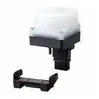


F39-BTLP
Lamp and Bluetooth Communication Unit, F3SG-R Series Safety Light Curtain
- Manufacturer: OMRON INDUSTRIAL AUTOMATION
- Product type:
- SVHC: To Be Advised
| Delivery and price | |
|---|---|
| Units per pack | 1 |
| Price | 90.13 € |
| Current stock | 10+ |
| Lead time | 30 days |
## Safety Light Curtain F3SG-R Series NEW 2 | Safety Light Curtain F3SG-R Series ## Increase both durability and productivity The new cutting oil resistant Robust type is added Safety Light Curtain Awa, \ ANY) LN **==> picture [140 x 123] intentionally omitted <==** **----- Start of picture text -----**<br> Tough1 Resistant to vibration<br>=<br>5 times*<br>Torsion resistance greater than<br>previous<br>model<br>\\ | |<br>W<br>Previous F3SG-R<br>model<br>**----- End of picture text -----**<br> **==> picture [307 x 48] intentionally omitted <==** **----- Start of picture text -----**<br> Tough Robust against Tough Reliable in dusty<br>- 2 environmental changes NNa 3 wash-down environments<br>y<br>Up to F3SG-RR<br>High power Operating range 20 IP67G<br>**----- End of picture text -----**<br> **==> picture [47 x 5] intentionally omitted <==** **----- Start of picture text -----**<br> F3SG-RA/RE:IP67<br>**----- End of picture text -----**<br> | 3 **A choice of products to suit your need**[Multiple versions available: finger, hand and arm protection] ## Ideal for flexible manufacturing > Multifunctional **Advanced** type **==> picture [28 x 10] intentionally omitted <==** **----- Start of picture text -----**<br> >>p.4<br>**----- End of picture text -----**<br> ## Even for environments where cutting oil is present > Cutting oil resistant **Robust** type **>>p.10** N E W ## Ideal for simple applications > Simple **Easy** type **>>p.11** F3SG-RE mple functions st response time: 5 ms duced wiring I is a trademark or registered trademark of OMRON Corporation in Japan and other countries. icrosoft product screen shot(s) reprinted with permission from Microsoft Corporation. e Bluetooth® word mark and logos are registered trademarks owned by Bluetooth SIG, Inc. Any use of such marks by Omron is under license. ther company names and product names in this document are the trademarks or registered trademarks of their respective companies. 4 | Safety Light Curtain F3SG-R Series **Multifunctional Advanced** type ## F3SG- **RA** ## Quick and easy installation ## Intuitive and smart designs for fast set-up **TOP** (top-beam-state indicator) ## **Simple beam adjustment** Simply watch for the top and bottom indicators to illuminate when adjustment is completed. The optional laser pointer and lamp can be used to reduce the time required to set up the light curtain. F39-PTG Laser Pointer **1** The TOP indicator turns ON when — **Sh** ows the sensor direction ieANN the top beam is unblocked ~~|~~ **F39-LP Lamp** **Tu** rns ON when safety **ou** tput turns ON, **ma** king adjustment **ea** sier The incident light levels of each Also beam can be checked with the Configuration Tool SD Manager2 —_——————_ - > **2** The BTM indicator turns ON when the bottom beam is unblocked Sufficient Insufficient Green Red **==> picture [10 x 4] intentionally omitted <==** **----- Start of picture text -----**<br> BTM<br>**----- End of picture text -----**<br> **==> picture [64 x 5] intentionally omitted <==** **----- Start of picture text -----**<br> (bottom-beam-state indicator)<br>**----- End of picture text -----**<br> * Image for illustration purpose only. ## **Mounting brackets** Four types of mounting brackets provide vertical or vertical and horizontal adjustment even after mounting, making beam adjustment easier. ## **Standard fixed bracket** You can slide the F3SG-R up and down to make vertical adjustments afte **r** mounting on a safety fence. ## **Standard adjustable bracket** (sold separately) This bracket provides vertical as well as horizontal adjustment of ±15º. **==> picture [13 x 6] intentionally omitted <==** **----- Start of picture text -----**<br> ±15°<br>**----- End of picture text -----**<br> **Top/bottom adjustable bracket** (sold separately) Use this bracket at the to **p** and bottom of the F3SG- **R** to make horizontal adjustment of ±22.5º. **Top/bottom adjustable bracket** (for user-made mounting part) (sold separately) The wall mounting brac **ket** is not provided so that y **ou** can design your own wa **ll** mounting part. ±22.5° | 5 ## **Optical synchronization – No sync lines required** Optical synchronization eliminates the need of wiring for synchronization between the emitter and receiver. The resulting flexible wiring reduces disconnection risk and avoids noise sources. ## **Optical synchronization** **==> picture [493 x 204] intentionally omitted <==** **----- Start of picture text -----**<br> After<br>Start-up<br>sync<br>The top or bottom 5: Once synchronization<br>beam of the emitter is done, the emitter is<br>starts synchronizing kept synchronized<br>with the correspond- with the receiver while<br>ing beam of the at least one beam is<br>receiver. unblocked.<br>Smartclick cable connection *<br>@nartclick<br>for fast set-up<br>No torque-control required: Click!<br>the Smartclick connectors connect cables with just a 1/8th turn<br>of the M12 waterproof connector. Insert<br>fully<br>1/8th turn<br>Receiver<br>Receiver<br>Emitter<br>Emitter<br>**----- End of picture text -----**<br> ## **Smartclick cable connection for fast set-up** No torque-control required: the Smartclick connectors connect cables with just a 1/8th turn of the M12 waterproof connector. * Smartclick is a registered trademark of OMRON Corporation. **==> picture [89 x 22] intentionally omitted <==** **----- Start of picture text -----**<br> Just a 1/8th turn<br>to connect<br>**----- End of picture text -----**<br> ## **Simple wiring thanks to reduced wiring connectors** Simple wiring makes installation faster. Fewer cables reduce disconnection risk and noise trouble. **==> picture [153 x 21] intentionally omitted <==** **----- Start of picture text -----**<br> Only one cable<br>Cables of the emitter and<br>receiver<br>**----- End of picture text -----**<br> 6 | Safety Light Curtain F3SG-R Series **Multifunctional Advanced** Stable operation and predictive maintenance type F3SG- **RA** ## Visualization eliminates machine downtime ## **Data logging for quick troubleshooting** ## **The lamp notifies low light intensity** **The error logs stored in the F3SG-RA can be downloaded to a PC that is connected with the F3SG-RA using the dedicated interface unit. The Confguration Tool SD Manager2 can be used to analyze errors to identify causes and solutions. The data on light intensity, power-ON time, and switching frequency can also be collected regularly for predictive maintenance.** The la **mp notifes when the incident light level drops due to** dirt, w **hich prevents sudden stops.** **==> picture [118 x 101] intentionally omitted <==** **----- Start of picture text -----**<br> The lamp notifes when<br>the light intensity drops<br>near the threshold*<br>0 Time<br>* The incident light level at which the<br> ligh t curtain turns OFF<br>Light intensity<br>**----- End of picture text -----**<br> **Confguration Tool SD Manager2** **==> picture [173 x 105] intentionally omitted <==** **----- Start of picture text -----**<br> F39-BT/BTLP Bluetooth®<br>Communication Unit<br>© Bluetoothiw<br>**----- End of picture text -----**<br> **==> picture [40 x 8] intentionally omitted <==** **----- Start of picture text -----**<br> F39-LP Lamp<br>**----- End of picture text -----**<br> ## **Bluetooth® allows to check status without stopping the line** The S **D Manager2 can be used to check the status of the safety light curtain** wirel **essly after pairing the safety light curtain with PC via Bluetooth®, which** reduc **es maintenance time.** **Line A** **Wireless connectivity** **- Monitoring during operation** **- No possibility of blocking beams** **- No work required after completing checks** - **Monitoring from anywhere** **- Serial number to choose the right safety light curtain from many installed on lines** **Line B** | 7 ## For global use ## Easy to deploy around the world ## **PNP/NPN selection** **The F3SG-RA is designed to be used in a variety of environments around the world, co** nforming to international nforming to international **standards.** ## **Global production and delivery** Omron enhanced the global production bases and local services in Japan, China, United States, and Europe to deliver Omron products quickly and reliably. Our sales network of approximately 150 offices in 40 countries and regions supports our customers. **NPN Global PNP** In **ternationa** l **Standard IEC** » -£ **ISO PNP or NPN can be selected T** he F3SG-R conforms to majo he F3SG-R conforms to majo **r with the DIP switch. The same international standards including cables are used Chinese GB standards** ## **Troubleshooting in eight languages*** **You can fnd causes a** nd solutions of errors that occur during **operation on the trou** bleshooting webpage in eight languages. **Operators across the** world can check the error details in their local **languages, which will** help them minimize time to troubleshoot. *** English, Chinese, Italia** n, Korean, French, German, Spanish, and Japanese Scan the QR code and go directly to the troubleshooting webpage **==> picture [6 x 10] intentionally omitted <==** **----- Start of picture text -----**<br> Line<br>B<br>**----- End of picture text -----**<br> Select the status of the indicator So 8 | Safety Light Curtain F3SG-R Series ## Easy adjustment ## **Multifunctional** Easy adjustment **Advanced** type Increase productivity by detecting F3SG- **RA** workpieces correctly F3SG- **RA** ## **Muting** The F3SG-RA provides the advanced Muting function that disables beams which detect the presence of a workpiece or the position of a machine or robot. Workpieces can go in and out of a danger zone without stopping the machine. **==> picture [248 x 70] intentionally omitted <==** **----- Start of picture text -----**<br> Conventional Muting Muting secured safety, but the set-up was time consuming.<br>=<br>[Installation/wiring/adjustment]<br>[.] Many wires<br>[.] Many accessories<br>[.] Complex adjustment<br>**----- End of picture text -----**<br> Time-consuming partial muting* setting for workpieces with various heights Incorrect muting due to a rotated and shifted workpiece Incorrect muting when a workpiece with holes (e.g., car body) passes at low speed Incorrect muting due to chattering in the muting signal when a workpiece is vibrating Two auto-configuration functions significantly Adjustment F3SG-R reduce the adjustment time even under difficult time reduced by conditions where failure is likely to occur. 80%[*] - * Compared to the previous model (Omron survey as of March 2017) Multiple-beam sensor technology for vibrating workpieces ## Smart muting actuator ## F3W-MA The smart muting actuator extends the functions of the F3SG-R in applications where a workpiece is vibrating forward and backward This prevents unexpected machine downtime and significantly reduces adjustment time. ## Automatic partial muting for workpieces with various heights ## Dynamic Muting When workpieces with various heights are conveyed on the same line, the dynamic muting function automatically sets the appropriate bea **ms, based on the height of the object.** **==> picture [85 x 7] intentionally omitted <==** **----- Start of picture text -----**<br> Smart muting actuator F3W-MA<br>**----- End of picture text -----**<br> * Partial muting: A function that allows specified beams (e.g., beams blocked by a workpiece) to be disabled, keeping others active, even during muting. | 9 ## Easy configuration and maintenance ## Configuration Tool SD Manager2 Easy to use | ## **Minimizing setting and detection errors** The Configuration Tool SD Manager2 visualizes the installation positions and settings by logging the muting sensor operating conditions of the F3SG-R. It helps ensure reliable, first-time-right configuration. **==> picture [431 x 503] intentionally omitted <==** **----- Start of picture text -----**<br> M u tin g st a tistics<br>information<br>Visualization<br>helps facilitate<br>adjustment<br>Eval uates settings using Muting time setting range<br>logg ed results<br>Assumed range<br>Examples of logging<br>Low risk of intermittent stop, OK in a test run, but intermittent stop Test run result is out of setting range.<br>= but not safe may occur during long-term operations . Muting sequence error occurred<br>OK, but big diference Assumed range Measured values<br>between assumed and > Setting range > Setting range<br>setting ranges<br>safer operation range<br>From configuration and The SD Manager2 helps you to understand Easy- to- a)<br>adjustment to maintenance make and change settings. icons oea|<br>Examples<br>Monitoring I/O Setting Function Setting<br>Incident/ambient Maintenance Auxiliary output/<br>light level monitoring information lamp Fixed blanking Muting/override<br>LL) =| . i= G)<br>Monitor incident light levels Check error log and other data Change the settings assigned to each Set disabled beams manually Set disabled beams and time.<br>of each beam for fine tuning required for maintenance output including lamp color and pattern or by teach-in Setting can be evaluated<br>The Configuration Tool SD Manager2 is available to download from<br>Omron website:<br>http://www.ia.omron.com/f3sg-r_tool<br>**----- End of picture text -----**<br> 10 | Safety Light Curtain F3SG-R Series ## N E W IP67G **Cutting oil resistant Robust** type Robust design for reliable use even in F3SG- **RR** cutting oil environments ## **Four times longer* cutting oil resistance** **==> picture [422 x 295] intentionally omitted <==** **----- Start of picture text -----**<br> The F3SG-RR has the ability to protect<br>from cutting oil (IP67G) for four times<br>longer than the previous model. 4<br>‘ | 4 i<br>a | * [tad]<br>Previous model<br>F3SG-RR<br>F3SJ-A/B<br>* Compared to the previous model<br> (Omron survey as of March 2017)<br>Unique construction<br>No gaps Patented<br>The optical surface is completely covered with rubber, and the<br>/ metal parts placed on the rubber are compressed and deformed<br>|| to seal tightly. This construction does not use double-sided tape ! \<br>that oil can penetrate, preventing cutting oil from getting inside.<br>r a |<br>Cutting oil<br>Completely blocked<br>Service life<br>Cutting oil<br>**----- End of picture text -----**<br> ## **No dead space** The F3SG-R perfectly fits to machines without wasting space. Thanks to the Cascade Connection function and perfect fit installation, you can series-connect light curtains to fit various protective heights, reducing inventories. **==> picture [172 x 97] intentionally omitted <==** **----- Start of picture text -----**<br> The detection zone<br>completely covers the joint<br>\<br>Po------H-H---e- 25-mm dia. \<br>n<br>Example of 25 m m detection capability<br>**----- End of picture text -----**<br> *1. Up to three sets of F3SG-R (up to 255 beams in total) can be series-connected. - *2. Protect cascading cables from cutting oil. | 11 **==> picture [56 x 54] intentionally omitted <==** **----- Start of picture text -----**<br> Simple<br>Easy<br>type<br>F3SG- RE<br>**----- End of picture text -----**<br> ## Reduced wiring and fast response ## Simple ON/OFF detection ## **Easy version for cost-efficiency** The Easy type inherits the robust but slim housing and basic safety features of the Advanced type. Simple ON/OFF detection reduces errors, preventing productivity from dropping. **==> picture [138 x 63] intentionally omitted <==** **----- Start of picture text -----**<br> Simple safety functions to reduce errors<br>and save costs<br>Reduced to just 4 wires<br>Fastest response time of 5 ms<br>**----- End of picture text -----**<br> Industry's fastest class* ## **Easier to build safety circuits** Only four wires are required for the minimum configuration, which is as simple as wiring a photoelectric sensor. Simple connection with a safety controller makes it easy to build a safety circuit. ## **Fastest response time of 5 ms** The Easy type that allows the distance between the light curtain and hazard source to be reduced is ideal for the use in a small machine. * Omron survey as of March 2017 **==> picture [141 x 129] intentionally omitted <==** **----- Start of picture text -----**<br> Emitter Receiver<br>Y-Joint<br>connector<br>with 4 wires<br>G9SE<br>ie,<br>Power supply<br>**----- End of picture text -----**<br> ## Also ## **Use easy-to-obtain cables** Commercially available M12 connector cables can be used as extension cables to build a safety circuit. 12 | Safety Light Curtain F3SG-R Series **List of specifications and features Advanced type Robust type** F3SG-RA F3SG-RR Ideal for Ideal for flexible environments where manufacturing cutting oil is present Application Finger protection ~~• •~~ Hand and arm protection ~~• •~~ Body protection ~~Tr~~ Specification Detection capability 14-mm dia. 30-mm dia. 14-mm dia. 25-mm dia. Beam gap 10 mm 20 mm 10 mm 20 mm Operating range 0.3 to 10 m 0.3 to 20 m 0.3 to 10 m 0.3 to 17 m Protective height 160 to 2,080 mm 190 to 2,510 mm 240 to 1,920 mm Number of beams 15 to 207 8 to 124 23 to 191 12 to 96 Feature PNP/NPN Selection External Test *1 *1 Interlock Pre-Reset External Device Monitoring (EDM) Auxiliary Output Muting Blanking Reduced Resolution Warning Zone Scan Code Selection Operating Range Selection - Response Time Adjustment Designated Beam Output ~~ran~~ Connection/ Cascade Connection wiring Reduced wiring Environmental resistance Degree of protection IP67 IP67,IP67G Accessory Lamp Bluetooth communication unit SD Manager2 Laser pointer ~~•••• ••••~~ Page 16 More information Page 44 (F3SG-RA-01TS : Page 93, F3SG-RA-02TS : Page 120[*2] ) *1. Supports PNP/NPN by switching between 0 V and 24 V active. *2. The F3SG-RA- □ TS has different specifications. See the pages listed above for details. ~~auu~~ Setting by DIP Switch Setting by Configuration Tool Setting by Wiring Setting by End Cap/Key Cap | 13 **==> picture [509 x 673] intentionally omitted <==** **----- Start of picture text -----**<br> Easy type More slim – F3SJ Series<br>F3SG-RE F3SJ-E F3SJ-B F3SJ-A<br>Ideal for<br>simple<br>applications<br>• Finger protection Application<br>Ge<br>• • • Hand and arm protection<br>a<br>••• Body protection<br>es<br>14-mm dia. 30-mm dia. 25-mm dia. 25-mm dia. 14/20/30/55-mm dia. Detection capability Specification<br>a<br>10 mm 20 mm 20 mm 20 mm 9/15/25/50 mm Beam gap<br>a<br>0.3 to 10 m 0.3 to 20 m 0.2 to 7 m 0.2 to 7 m 0.2 to 9 m *3 Operating range<br>eG<br>160 to 2,080 mm 190 to 2,510 mm 185 to 1,105 mm 185 to 2,065 mm 245 to 2,495 mm *3 Protective height<br>Ge<br>15 to 207 8 to 124 8 to 54 8 to 102 Varies depending on the beam gap *3 Number of beams<br>es - - - - PNP/NPN Selection Feature<br>eC<br>- External Test<br>es<br>- - Interlock<br>=<br>- - - - Pre-Reset<br>a - - On External Device Monitoring (EDM)<br>Oe<br>- - - Auxiliary Output<br>GO - - / — + SO Muting<br>ee<br>- - - Blanking<br>a - - - - Reduced Resolution<br>eG<br>- - - Warning Zone<br>a - (Not required for wired synchronization) Scan Code Selection<br>a - - Operating Range Selection<br>a<br>- - - - Response Time Adjustment<br>a<br>- - - Designated Beam Output<br>ee - - — S Cascade Connection Connection/<br>wiring<br>- Reduced wiring<br>ee<br>a IP67 IP65 IP65 IP65 Degree of protection ee Environmental resistance<br>a - - - • Lamp Accessory<br>a - - - - Bluetooth communication unit<br>a - - - SD Manager SD Manager2<br>a<br>• • • • Laser pointer<br>a<br>Page 73 Refer to the F3SJ Series Catalog (Cat. No. F074). More information<br>a<br>*3. Varies depending on the model.<br>Refer to the F3SJ Series Catalog (Cat. No. F074) or visit the Omron website for details of the F3SJ Series. For details | F3SJ Se a rch www.ia.omron.com/<br>**----- End of picture text -----**<br> **==> picture [554 x 739] intentionally omitted <==** **----- Start of picture text -----**<br> 14 | Safety Light Curtain F3SG-R Series<br>Flowchart for product section<br>High functionality<br>F3SG-R Series<br>Advanced type<br>Application<br>F3SG-RA<br>Finger/hand/arm<br>protection ・・Quick and easy installation Stable operation and predictive mai<br>・For global use<br>Robust body without Muting/Blanking Cutting oil ・Easy adjustment<br>cover required YES • Machine partially YES resistance NO ・Easy configuration and maintenance<br>• Possibility of accidental located in the detection Exposed to<br> contact zone cutting oil<br>• Wash-down NO Cutting oil resistant<br>• Distinguish workpieces<br> environment from operators<br>YES<br>F3SG-R Series<br>High power NO Robust type<br>required for stable YES F3SG-RR<br>• Dusty environment<br>• Operating range ≥ 10 m • Four times longer<br>NO<br> cutting oil resistance<br>• IP67G<br>• No dead space<br>Simple application<br>START<br>F3SG-R Series<br>Easy type<br>F3SG-RE<br>Application<br>Blanking<br>Leg/body protection • Simple functions<br>Machine partially located • Reduced wiring<br>in the detection zone<br>• Fast response time: 5 ms<br>= YES<br>YES NO F3SJ Series<br>EASY type<br>F3SJ-E<br>NO<br>Muting Simple wiring<br>• Simple functions<br>Distinguish NO Reduced wiring<br>workpieces from connectors for easy YES F3SJ Series<br>operators installation BASIC type<br>YES YES F3SJ-B<br>• Series-connection<br>Cutting oil • Muting<br>resistance NO F3SJ Series<br>Exposed to ENVIRONMENT RESISTANT type<br>cutting oil YES F3SJ-B-02TS<br>F3SJ Series<br>ADVANCED type<br>F3SJ-A<br>• Series-connection<br>• Up to 55 mm detection capability<br>• Muting<br>**----- End of picture text -----**<br> | 15 **==> picture [446 x 617] intentionally omitted <==** **----- Start of picture text -----**<br> Protective height Specifications Brackets Cable Accessories (sold separately)<br>Detection capability Accessory Connector<br>14-mm dia./30-mm dia. ・St andard fixed brac ket Single/double-ended connector cable<br>Cascading cable<br>Beam gap<br>Reduced wiring connector<br>10 mm/20 mm<br>Laser pointer<br>Operating range Sold separately<br>Spatter protection cover<br>160 to 2,080 mm14-mm dia. 0.3 to 10 m/0.3 to 20 m ・・・Standard adjustable bracketTop/bottom adjustable bracketTop/bottom adjustable bracket LampBluetoothcommunication unit<br>(15 to 207 beams) (for user-made mounting part)<br>30-mm dia. SD Manager2<br>190 to 2,510 mm * The F3SG-RA-□TS has different specifications.<br>(8 to 124 beams) See the following pages:F3SG-4RA-01TS: p. 93 F3SG-RA-02TS: p. 120 See p.16 for details.<br>Detection capability Sold separately Connector<br>14-mm dia./25-mm dia. ・Free-Location Single/double-ended connector cable<br> Bracket Cascading cable<br>Beam gap (Intermediate Bracket)<br>・Top/bottom Reduced wiring connector<br>10 mm/20 mm Bracket (3types)<br>Laser pointer<br>Operating range<br>Lamp<br>0.3 to 10 m/ Bluetooth communication unit<br>14-mm dia. 0.3 to 17 m<br>240 to 1,920 mm SD Manager2<br>(23 to 191 beams)<br>25-mm dia.<br>240 to 1,920 mm<br>(12 to 96 beams) See p.44 for details.<br>Detection capability Accessory Connector<br>14-mm dia./30-mm dia. ・Standard fixed Bracket Single/double-ended connector cable<br>Reduced wiring connector<br>Beam gap<br>Laser pointer<br>10 mm/20 mm<br>Spatter protection cover<br>Operating range Sold separately<br>0.3 to 10 m/ ・Standard adjustable bracket<br>160 to 2,080 mm14-mm dia. 0.3 to 20 m ・・Top/bottom adjustable bracketTop/bottom adjustable bracket<br>(15 to 207 beams) (for user-made mounting part)<br>30-mm dia.<br>el |<br>190 to 2,510 mm<br>(8 to 124 beams) See p.73 for details.<br>Detection capability<br>25-mm dia.<br>Beam gap<br>20 mm Refer to the F3SJ Series Catalog (Cat.<br>Operating range No. F074) or visit the Omron website<br>25-mm dia.<br>185 to 1,105 mm 0.2 to 7 m for details of the F3SJ Series.<br>(8 to 54 beams)<br>Detection capability<br>25-mm dia.<br>Beam gap<br>20 mm<br>Operating range<br>0.2 to 7 m<br>25-mm dia.<br>185 to 2,065 mm<br>(8 to 102 beams)<br>* ENVIRONMENT RESISTANT type<br> Protective height: 225 to 1,985 mm Operating range: 0.2 to 6 m<br>**----- End of picture text -----**<br> **==> picture [139 x 84] intentionally omitted <==** **----- Start of picture text -----**<br> Detection capability<br>14-mm dia. -<br>Beam gap<br>9 mm -<br>14-mm dia. Operating range<br>245 to 1,271 mm<br>(26 to 140 beams) 0.2 to 9 m<br>* When the minimum object resolution is 14 mm<br> and the beam gap is 9 mm.<br>**----- End of picture text -----**<br> **www.ia.omron.com/** **==> picture [128 x 6] intentionally omitted <==** **----- Start of picture text -----**<br> F3SJ Se a rch<br>**----- End of picture text -----**<br> **Safety Light Curtain Advanced type F3SG-RA** ## **Offers Both Durability and Reliability** - Rugged and compact - New muting function to increase both productivity and safety - All models designed for global use. PNP/NPN selection by DIP switch - Conforming to major international standards including Chinese standard GB/T 4584 ## **System Configuration** **==> picture [504 x 416] intentionally omitted <==** **----- Start of picture text -----**<br> Mounting bracket Accessory Accessory<br>' yarre<br>F39-LP F39-BT F39-BTLP<br>Lamp Bluetooth Lamp and Bluetooth<br>Communication Unit Communication Unit<br>F39-HGA@@@@ F39-PTG<br>F39-LGF Spatter Protection Cover Laser Pointer<br>Standard Fixed Bracket (for F3SG-RA)<br>(included as standard) Emitter Receiver<br>Recommended safety controller *<br>F39-JG@B Up to<br>NX/NE1A-series<br>Double-Ended Cable three sets<br>Safety Network Controller<br>F39-JGR2W<br>Cascading Cable<br>F39-LGA Emitter Receiver G9SP-series<br>Standard Adjustable Accessory Safety Controller<br>Bracket<br>PC<br>G9SE/G9SA-series<br>IF-U Safety Relay Unit<br>F39-GIF<br>Interface Unit Configuration Tool<br>SD Manager 2<br>G9SX-series<br>F39-JG@B Flexible Safety Unit<br>Double-Ended Cable<br>F39-JG@A<br>Single-Ended Cable<br> or G7SA/G7S-E<br>Accessory Relays with Forcibly<br>F39-LGTB Guided Contacts<br>F39-LGTB-1 F39-GCNY2 F3W-MA0100P<br>T op/Bottom Adjustable F39-JG@B-L F3W-MA0300P<br>Bracket F39-JG@A-D Smart Muting Actuator<br>Reduced wiring * The recommended safety controller is required to<br>connector system Note: See p.147 for details. build a safety circuit using emergency stop<br>**----- End of picture text -----**<br> - The recommended safety controller is required to build a safety circuit using emergency stop switches and door switches. **16** **F3SG-RA** ## **Ordering Information** ## **Main Units** ## **Safety Light Curtain Finger protection** ## **Hand and arm protection** |**Number of**<br>**beams**<br>15|**Protective height**<br>**(mm)**<br>160|**Model**<br>**F3SG-4RA0160-14**||**Number of**<br>**beams**<br>8|**Protective height**<br>**(mm)**<br>190|**Model**<br>**F3SG-4RA0190-30**| |---|---|---|---|---|---|---| |23|240|**F3SG-4RA0240-14**||12|270|**F3SG-4RA0270-30**| |31|320|**F3SG-4RA0320-14**||16|350|**F3SG-4RA0350-30**| |39|400|**F3SG-4RA0400-14**||20|430|**F3SG-4RA0430-30**| |47|480|**F3SG-4RA0480-14**||24|510|**F3SG-4RA0510-30**| |55|560|**F3SG-4RA0560-14**||28|590|**F3SG-4RA0590-30**| |63|640|**F3SG-4RA0640-14**||32|670|**F3SG-4RA0670-30**| |71|720|**F3SG-4RA0720-14**||36|750|**F3SG-4RA0750-30**| |79|800|**F3SG-4RA0800-14**||40|830|**F3SG-4RA0830-30**| |87|880|**F3SG-4RA0880-14**||44|910|**F3SG-4RA0910-30**| |95|960|**F3SG-4RA0960-14**||48|990|**F3SG-4RA0990-30**| |103|1040|**F3SG-4RA1040-14**||52|1070|**F3SG-4RA1070-30**| |111|1120|**F3SG-4RA1120-14**||56|1150|**F3SG-4RA1150-30**| |119|1200|**F3SG-4RA1200-14**||60|1230|**F3SG-4RA1230-30**| |127|1280|**F3SG-4RA1280-14**||64|1310|**F3SG-4RA1310-30**| |135|1360|**F3SG-4RA1360-14**||68|1390|**F3SG-4RA1390-30**| |143|1440|**F3SG-4RA1440-14**||72|1470|**F3SG-4RA1470-30**| |151|1520|**F3SG-4RA1520-14**||76|1550|**F3SG-4RA1550-30**| |159|1600|**F3SG-4RA1600-14**||80|1630|**F3SG-4RA1630-30**| |167|1680|**F3SG-4RA1680-14**||84|1710|**F3SG-4RA1710-30**| |175|1760|**F3SG-4RA1760-14**||88|1790|**F3SG-4RA1790-30**| |183|1840|**F3SG-4RA1840-14**||92|1870|**F3SG-4RA1870-30**| |191|1920|**F3SG-4RA1920-14**||96|1950|**F3SG-4RA1950-30**| |199|2000|**F3SG-4RA2000-14**||100|2030|**F3SG-4RA2030-30**| |207|2080|**F3SG-4RA2080-14**||104|2110|**F3SG-4RA2110-30**| |||||108|2190|**F3SG-4RA2190-30**| |||||112|2270|**F3SG-4RA2270-30**| |||||116|2350|**F3SG-4RA2350-30**| |||||120|2430|**F3SG-4RA2430-30**| |||||124|2510|**F3SG-4RA2510-30**| **17** **F3SG-RA** ## **Accessories (Sold separately) Safety light curtain connecting cable Single-Ended Cable *** |**Appearance**|**Type**<br>~~Se~~|**Cable length**<br>~~es~~|**Specifications**|**Model**| |---|---|---|---|---| |GF<br>-|For emitter<br>M12 connector<br>(5-pin), 5 wires<br>Color: Gray<br>~~Se~~<br>~~|~~|3 m<br>~~es~~<br>~~—~~|5<br>3<br>2<br>1<br>4<br>Female<br>1<br>2<br>3<br>4<br>5<br>+24 VDC<br>TEST<br>0 VDC<br>Not used<br>Not used<br>Brown<br>Black<br>Blue<br>White<br>Yellow<br>Connected to Power Cable or Double-Ended Cable<br>O °O<br>ec|**F39-JG3A-L**| |||7 m<br>~~—~~<br>~~=~~||**F39-JG7A-L**| |||10 m<br>~~—~~<br>~~=~~||**F39-JG10A-L**| |||15 m<br>~~=~~<br>~~|~~||**F39-JG15A-L**| |||20 m<br>~~|~~||**F39-JG20A-L**| ||For receiver<br>M12 connector<br>(8-pin), 8 wires<br>Color: Black|3 m|5<br>8<br>4<br>3<br>2<br>1<br>7<br>6<br>Female<br>2<br>7<br>5<br>6<br>1<br>+24 VDC<br>0 VDC<br>OSSD 1<br>OSSD 2<br>RESET<br>Brown<br>Blue<br>Black<br>White<br>Yellow<br>8<br>AUX<br>Red<br>3<br>MUTE A<br>Gray<br>4<br>MUTE B<br>Pink<br>Connected to Power Cable or Double-Ended Cable<br>OO<br>5|**F39-JG3A-D**| |||7 m<br>~~—~~||**F39-JG7A-D**| |||10 m<br>~~—~~<br>~~—~~||**F39-JG10A-D**| |||15 m<br>~~|~~<br>~~|~~||**F39-JG15A-D**| |||20 m<br>~~|~~||**F39-JG20A-D**| * A set of two Single-Ended Cables (one for emitter and one for receiver) is also available. Model: Model number without the -L/-D at the end (F39-JG@A) **Note:** To extend the cable length to more than 20 m, add the F39-JG@B Double-Ended Cable. ## **Double-Ended Cable *** **For cable extension and simple wiring** |**Appearance**|**Type**<br>~~es~~|**Cable length**<br>~~es~~|**Specifications**<br>~~es~~|**Model**| |---|---|---|---|---| |.<br>~——4|For emitter<br>M12 connector<br>(5-pin)<br>on both ends<br>Color: Gray<br>~~PS~~|0.5 m<br>~~|~~|Brown<br>Blue<br>Black<br>White<br>Yellow<br>1<br>3<br>2<br>4<br>5<br>5<br>3<br>2<br>1<br>4<br>Brown<br>Blue<br>Black<br>White<br>Yellow<br>1<br>3<br>2<br>4<br>5<br>Female<br>5<br>4<br>1<br>2<br>3<br>Male<br>Connected to Power Cable<br>or Double-Ended Cable<br>Connected to Single-Ended Cable,<br>or Double-Ended Cable<br>U<br>~~=o=—=~~|**F39-JGR5B-L**| |||1 m<br>~~|~~<br>~~|~~||**F39-JG1B-L**| |||3 m<br>~~|~~<br>~~=o~~||**F39-JG3B-L**| |||5 m<br>~~|~~<br>~~=o~~||**F39-JG5B-L**| |||7 m<br>~~=o~~||**F39-JG7B-L**| |||10 m<br>~~=o~~||**F39-JG10B-L**| |||15 m<br>~~PS~~||**F39-JG15B-L**| |||20 m<br>~~PS~~||**F39-JG20B-L**| ||For receiver<br>M12 connector<br>(8-pin)<br>on both ends<br>Color: Black<br>~~PS~~|0.5 m<br>~~PS~~|Brown<br>Blue<br>Black<br>White<br>Yellow<br>Red<br>Gray<br>Pink<br>Blue<br>Black<br>White<br>Yellow<br>Red<br>Gray<br>Pink<br>2<br>7<br>5<br>6<br>1<br>8<br>3<br>4<br>Brown<br>5<br>8<br>4<br>3<br>2<br>1<br>7<br>6<br>5<br>8<br>6<br>7<br>1<br>2<br>3<br>4<br>2<br>7<br>5<br>6<br>1<br>8<br>3<br>4<br>Connected to Power Cable<br>or Double-Ended Cable<br>Connected to Single-Ended Cable,<br>or Double-Ended Cable<br>Female<br>Male<br>eeee~~ee~~<br>+o~~t~~<br>~~|S~~ ~~oc~~<br>~~e~~a~~e~~|**F39-JGR5B-D**| |||1 m<br>~~PS~~<br>~~ee~~||**F39-JG1B-D**| |||3 m<br>~~ee~~<br>~~|e)~~||**F39-JG3B-D**| |||5 m<br>~~ee~~<br>~~|e)~~||**F39-JG5B-D**| |||7 m<br>~~|e)~~<br>~~|S~~||**F39-JG7B-D**| |||10 m<br>~~|S~~<br>~~—~~||**F39-JG10B-D**| |||15 m<br>~~|S~~<br>~~—~~||**F39-JG15B-D**| |||20 m<br>~~—~~||**F39-JG20B-D**| - A set of two Double-Ended Cables (one for emitter and one for receiver) is also available. Model: Model number without the -L/-D at the end (F39-JG@B) **Note:** To extend the cable length to more than 20 m, add the F39-JG@B Double-Ended Cable to the F39-JG@A Single-Ended Cable. To extend the cable length to more than 40 m, add several Double-Ended Cables to the Single-Ended Cable. Example: To extend the cable length to 50 m, connect two F39-JG20B (20 m) cables and one F39-JG10A (10 m) cable. ## **<Connection example>** **==> picture [233 x 76] intentionally omitted <==** **----- Start of picture text -----**<br> Emitter Cable is gray F39-JG@B-L (Gray) F39-JG@A-L (Gray)<br>a<br>Double-Ended Cable Single-Ended Cable<br>F39-JG@B F39-JG@A<br>Receiver Cable is black F39-JG@B-D (Black) F39-JG@A-D (Black)<br>**----- End of picture text -----**<br> **18** ~~i~~ **F3SG-RA** ## **Y-Joint Plug/Socket Connector for F3SG-4RA** @@@@ **-14/-4RA** @@@@ **-30 For reduced wiring** **==> picture [450 x 136] intentionally omitted <==** **----- Start of picture text -----**<br> Appearance Type Cable length Specifications Model<br>ee<br>F3SG-RA F3SG-RA<br>Emitter Receiver<br>M12 connectors.<br>Used for reduced 0.5 m F39-GCNY2<br>Y-Joint Plug/<br>wiring. Socket Connector for Advanced type<br>F39-GCNY2<br>Double-Ended Cable<br>F39-JG@B-L (Gray) *<br>Single-Ended Cable<br>F39-JG@A-D (Black) *<br>**----- End of picture text -----**<br> * Order the cable for emitter (end of model: -L) and the cable for receiver (end of model: -D). **Cascading Cable (2 cables per set, for emitter and receiver) Appearance Type Cable length Specifications Model** Secondary Secondary sensor 1 sensor 1 (Emitter) (Receiver) Emitter cable: Cap (5-pin), M12 Cascading Cable connector (5-pin) F39-JGR2W 0.2 m **F39-JGR2W** Receiver cable: Primary Primary Cap (8-pin), M12 sensor sensor connector (8-pin) (Emitter) (Receiver) Cable Cable F39-JG@@@-L F39-JG@@@-D ~~A~~ **Note:** The Double-Ended Cable (up to 10 m: F39-JG10B) can be added to extend the cable length between the series-connected sensors. Cable length between sensors: 10 m max. (not including cascading cable (F39-JGR2W) and power cable) **<Connection example>** Remove the cap Cable is gray Cable is gray **Emitter Emitter** F39-JG@B-L (Gray) ~~qe cr oe~~ Double-Ended Cable Cascading Cable F39-JG@B F39-JGR2W **Receiver** F39-JG@B-D (Black) ~~i~~ Cable is black ~~Te~~ **Receiver** Cable is black Remove the cap **19** omron ~~a~~ **F3SG-RA** ## **Sensor Mounting Brackets** |**Specification**|**Application**| |---|---| |Standard Fixed<br>Bracket|Bracket to mount the F3SG-R.<br>Side mounting and backside mounting possible.<br>(This is included as a standard accessory with the<br>product. It comes as a set of two Brackets. Refer to note<br>*1 for the number of sets provided with each model.)| |Standard<br>Adjustable<br>Bracket|Bracket to mount the F3SG-R.<br>Beam alignment after mounting possible.<br>The angle adjustment range is±15°.<br>Side mounting and backside mounting possible.<br>(Sold separately as a set of two Brackets. Refer to note<br>*1 for the number of sets required for each model.)| |Top/Bottom<br>Adjustable Bracket *2|Bracket to mount the F3SG-R. Use this bracket at the<br>top and bottom positions of the F3SG-R.<br>Beam alignment after mounting possible.<br>The angle adjustment range is±22.5°.<br>Side mounting and backside mounting possible.<br>(Sold separately. 4 brackets per set.)| |Top/Bottom<br>Adjustable Bracket *2<br>(For user-made mounting<br>part)|Top/Bottom Adjustable Bracket without a bracket to<br>mount to the wall. Use the user's own wall mounting part<br>to suit the machine.<br>(Sold separately. 4 brackets per set.)| - *1. [for F3SG-4RA@@@@-14] - Protective height of 0160 to 1200: 2 sets, Protective height of 1280 to 2080: 3 sets - [for F3SG-4RA@@@@-30] - Protective height of 0190 to 1230: 2 sets, Protective height of 1310 to 2270: 3 sets, Protective height of 2350 to 2510: 4 sets - *2. Top/Bottom Adjustable Bracket cannot be used with the Standard Fixed Bracket. Use with the Standard Adjustable Bracket. Using Top/Bottom Adjustable Brackets with Standard Adjustable Brackets F3SG-4RA@@@@-14: Protective height of 1040 or less: The Standard Adjustable Bracket is not required. Please purchase 1 set of Top/Bottom Adjustable Brackets (F39-LGTB(-1)). Protective height of 1120 to 1920: Please purchase 1 set of Top/Bottom Adjustable Brackets (F39-LGTB(-1)) and 1 set of Standard Adjustable Brackets (F39-LGA). Protective height of 2000 to 2080: Please purchase 1 set of Top/Bottom Adjustable Brackets (F39-LGTB(-1)) and 2 sets of Standard Adjustable Brackets (F39-LGA). F3SG-4RA@@@@-30: Protective height of 1070 or less: The Standard Adjustable Bracket is not required. Please purchase 1 set of Top/Bottom Adjustable Brackets (F39-LGTB(-1)). Protective height of 1150 to 1950: Please purchase 1 set of Top/Bottom Adjustable Brackets (F39-LGTB(-1)) and 1 set of Standard Adjustable Brackets (F39-LGA). Protective height of 2030 to 2510: Please purchase 1 set of Top/Bottom Adjustable Brackets (F39-LGTB(-1)) and 2 sets of Standard Adjustable Brackets (F39-LGA). **20** **F3SG-RA** ## **Interface units and configuration tool SD Manager 2** |**Appearance**|**Type**|**Specifications**|**Model**| |---|---|---|---| ||SD Manager 2|The Configuration Tool SD Manager 2 is<br>available to download from our website at<br>http://www.ia.omron.com/f3sg-r_tool.<br>To change the settings of the F3SG-RA using<br>SD Manager 2, it is necessary to set the receiver's<br>two DIP switches No. 8 to ON.|−| |ae|Interface Unit|F39-GIF interface unit to connect the F3SG-RA<br>receiver to a USB port of the PC<br>Accessories:<br>0.3-m Dedicated Cable 1 (1),<br>2-m Dedicated Cable 2 (1),<br>Instruction Manual|**F39-GIF**| ||Bluetooth<br>Communication Unit|F39-BT bluetooth unit to enable bluetooth on the<br>F3SG-RA<br>IP67 rated when mated.|**F39-BT**| ## **Lamp** |||**Appearance**|**Type**<br>**Specifications**|**Model**| |---|---|---|---|---| ||||Lamp<br>The lamp can be connected to a receiver and turned ON<br>based on the operation of F3SG-RA/RR.|**F39-LP**| ||||The lamp can indicate red, orange, and green colors,|| ||||to which three different states can be assigned.<br>IP67 rated when mated.<br>Lamp and Bluetooth<br>Communication Unit|**F39-BTLP**| ||**End Cap**|||| |**Laser Pointer for F3SG-R**<br>**Appearance**<br>**Appearance**<br>~~.~~<br>~~i~~|||**Specifications**<br>Housing color: Black<br>For both emitter and receiver<br>(Attached to the F3SG-RA. The End Cap can be purchased if lost.)<br>IP67 rated when mated.<br>**Specifications**<br>The laser pointer is attached on the optical surface of the F3SG-R to help coarse<br>adjustment of beams.|**Model**<br>**F39-CNM**<br>**Model**<br>**F39-PTG**| **21** omron [Ny **F3SG-RA** ## **Spatter Protection Cover (2 covers per set, one for emitter and one for receiver)** ## Spatter Protection Covers include mounting brackets. For Safety Light Curtain models of the protective height of 2,000 mm or longer, use two Spatter Protection Covers of different lengths. |**Appearance**|**Safety Light Curtain Model**|**Safety Light Curtain Model**|**Model**| |---|---|---|---| ||**Finger protection**|**Hand and arm protection**|| |~~BS~~|**F3SG-4RA0160-14**|**F3SG-4RA0190-30**|**F39-HGA0200**| ||**F3SG-4RA0240-14**|**F3SG-4RA0270-30**|**F39-HGA0280**| ||**F3SG-4RA0320-14**|**F3SG-4RA0350-30**|**F39-HGA0360**| ||**F3SG-4RA0400-14**|**F3SG-4RA0430-30**|**F39-HGA0440**| ||**F3SG-4RA0480-14**|**F3SG-4RA0510-30**|**F39-HGA0520**| ||**F3SG-4RA0560-14**|**F3SG-4RA0590-30**|**F39-HGA0600**| ||**F3SG-4RA0640-14**|**F3SG-4RA0670-30**|**F39-HGA0680**| ||**F3SG-4RA0720-14**|**F3SG-4RA0750-30**|**F39-HGA0760**| ||**F3SG-4RA0800-14**|**F3SG-4RA0830-30**|**F39-HGA0840**| ||**F3SG-4RA0880-14**|**F3SG-4RA0910-30**|**F39-HGA0920**| ||**F3SG-4RA0960-14**|**F3SG-4RA0990-30**|**F39-HGA1000**| ||**F3SG-4RA1040-14**|**F3SG-4RA1070-30**|**F39-HGA1080**| ||**F3SG-4RA1120-14**|**F3SG-4RA1150-30**|**F39-HGA1160**| ||**F3SG-4RA1200-14**|**F3SG-4RA1230-30**|**F39-HGA1240**| ||**F3SG-4RA1280-14**|**F3SG-4RA1310-30**|**F39-HGA1320**| ||**F3SG-4RA1360-14**|**F3SG-4RA1390-30**|**F39-HGA1400**| ||**F3SG-4RA1440-14**|**F3SG-4RA1470-30**|**F39-HGA1480**| ||**F3SG-4RA1520-14**|**F3SG-4RA1550-30**|**F39-HGA1560**| ||**F3SG-4RA1600-14**|**F3SG-4RA1630-30**|**F39-HGA1640**| ||**F3SG-4RA1680-14**<br>~~BS~~|**F3SG-4RA1710-30**<br>|**F39-HGA1720**| ||**F3SG-4RA1760-14**<br>~~BS~~|**F3SG-4RA1790-30**<br>|**F39-HGA1800**| ||**F3SG-4RA1840-14**<br>~~BS~~|**F3SG-4RA1870-30**<br>|**F39-HGA1880**| ||**F3SG-4RA1920-14**<br>~~BS~~|**F3SG-4RA1950-30**<br>|**F39-HGA1960**| ||**F3SG-4RA2000-14**<br>~~BS~~|**F3SG-4RA2030-30**<br>|**F39-HGA1480**| ||||**F39-HGA0550**| ||**F3SG-4RA2080-14**<br>~~——~~|**F3SG-4RA2110-30**<br>~~——~~|**F39-HGA1560**| ||||**F39-HGA0550**| ||−<br>~~——~~|**F3SG-4RA2190-30**<br>~~——~~|**F39-HGA1640**| ||||**F39-HGA0550**| ||−<br>~~——~~<br>~~a~~|**F3SG-4RA2270-30**<br>~~——~~<br>~~a~~|**F39-HGA1720**| ||||**F39-HGA0550**| ||−<br>~~a~~|**F3SG-4RA2350-30**<br>~~a~~|**F39-HGA1800**| ||||**F39-HGA0550**| ||−<br>~~——~~|**F3SG-4RA2430-30**<br>~~——~~|**F39-HGA1880**| ||||**F39-HGA0550**| ||−<br>~~——~~|**F3SG-4RA2510-30**<br>~~——~~|**F39-HGA1960**| ||||**F39-HGA0550**| **Note: 1.** The operating range of the Safety Light Curtain attached with the product is 10% shorter than the rating. **2.** The product extends over the DIP Switch cover of the Safety Light Curtain. Be sure to use the product only after all required settings are made to the DIP Switch. ## **Test Rod** **Diameter Model** 14 mm dia. **F39-TRD14** 30 mm dia. **F39-TRD30** ~~——~~ **22** **F3SG-RA** ## **Ratings and Specifications** ## **Main unit** The @@@@ in the model names indicate the protective heights in millimeters. ||||**F3SG-4RA****-14**<br>**F3SG-2RA****-14**|**F3SG-4RA****-14**<br>**F3SG-2RA****-14**|**F3SG-4RA****-30**<br>**F3SG-2RA****-30**| |---|---|---|---|---|---| |**Type of ESPE (IEC 61496-1)**||**Type 4**|F3SG-4RA-14/-30||| |||**Type 2**|F3SG-2RA-14/-30||| |**Performance**|**Object Resolution**<br>**(Detection Capability)**||Opaque objects||| ||||14-mm dia.||30-mm dia.| ||**Beam Gap**||10 mm||20 mm| ||**Number of Beams**||15 to 207||8 to 124| ||**Lens Size**||5.2 × 3.4 (W × H) mm||7-mm dia.| ||**Protective Height**||160 to 2080 mm (6.3 to 81.9 inch)||190 to 2510 mm (7.3 to 98.7 inch)| ||**Operating Range**|**Long**|0.3 to 10.0 m (1 to 32 ft.)||0.3 to 20.0 m (1 to 65 ft.)| |||**Short**|0.3 to 3.0 m (1 to 10 ft.)||0.3 to 7.0 m (1 to 23 ft.)| ||**Response Time**|**ON to OFF**|Normal mode: 8 to 18 ms max. *1<br>Slow mode: 16 to 36 ms max. *1 *2||| |||**OFF to ON**|40 to 90 ms max. *1||| |||*1. Response time when used in one segment system or in cascaded connection.<br>Refer to page 25 for the one segment system. Refer to_Safety Light Curtain F3SG-R Series User's Manual (ManNo.:_<br>_Z352)_for cascaded connection.<br>*2. Selectable by Configuration Tool.|||| ||**Effective Aperture Angle**<br>**(EAA) (IEC 61496-2)**|**Type 4**|±2.5° max., emitter and receiver at operating range of 3 m or greater||| |||**Type 2**|±5.0° max., emitter and receiver at operating range of 3 m or greater||| ||**Light Source**||Infrared LEDs, Wavelength: 870 nm||| ||**Startup Waiting Time**||2 s max.||| |**Electrical**|**Power Supply Voltage (Vs)**||SELV/PELV 24 VDC±20% (ripple p-p 10% max.)||| ||**Current Consumption**|||Refer to page 25 .|| ||**Safety Outputs (OSSD)**||Two PNP or NPN transistor outputs (PNP or NPN is selectable by DIP Switch.)<br>Load current of 300 mA max., Residual voltage of 2 V max. (except for voltage drop due to cable<br>extension), Capacitive load of 1μF max., Inductive load of 2.2 H max. *1<br>Leakage current of 1 mA max. (PNP), 2 mA max. (NPN) *2<br>*1. The load inductance is the maximum value when the safety output frequently repeats ON and<br>OFF. When you use the safety output at 4 Hz or less, the usable load inductance becomes<br>larger.<br>*2. These values must be taken into consideration when connecting elements including a<br>capacitive load such as a capacitor.||| ||**Auxiliary Output**||One PNP or NPN transistor output (PNP or NPN is selectable by DIP Switch.)<br>Load current of 100 mA max., Residual voltage of 2 V max .||| ||**Output Operation**<br>**Mode**|**Safety Output**|Light-ON (Safety output is enabled when the receiver receives an emitting signal.)||| |||**Auxiliary Output**|Safety output (Inverted signal output:Enable) (default) (Cofigurable by Configuration Tool)||| ||**Input Voltage**|**ON Voltage**|TEST:<br>24 V Active: 9 V to Vs (sink current 3 mA max.) *<br>0 V Active: 0 to 3 V (source current 3 mA max.)<br>MUTE A/B:<br>PNP: Vs to Vs-3 V (sink current 3 mA max.) *<br>NPN: 0 to 3 V (source current 3 mA max.)<br>RESET:<br>PNP: Vs to Vs-3 V (sink current 5 mA max.) *<br>NPN: 0 to 3 V (source current 5 mA max.)||| |||**OFF Voltage**|TEST:<br>24 V Active : 0 to 1.5 V or open<br>0 V Active : 9 V to Vs or open<br>MUTE A/B, RESET:<br>PNP: 0 to 1/2 Vs, or open *<br>NPN: 1/2 Vs to Vs, or open *||| |||* The Vs indicates a supply voltage value in your environment.|||| ||**Overvoltage Category (IEC 60664-1)**||II||| ||**Indicators**|||Refer to page 27.|| ||**Protective Circuit**||Output short protection, Power supply reverse polarity protection||| ||**Insulation Resistance**||20 MΩor higher (500 VDC megger)||| ||**Dielectric Strength**||1,000 VAC, 50/60 Hz (1 min)||| |**Functional**|**Mutual Interference Prevention (Scan Code)**||This function prevents mutual interference in up to two F3SG-RA systems.||| ||**Cascade Connection**||Number of cascaded segments: 3 max.<br>Total number of beams: 255 max.<br>Cable length between sensors: 10 m max.<br>(not including cascading cable (F39-JGR2W) and power cable)||| ||**Test Function**||Self-test (at power-on, and during operation)<br>External test (light emission stop function by test input)||| ||**Safety-Related Functions**||Interlock<br>External device monitoring (EDM)<br>Pre-reset<br>Fixed blanking/Floating blanking<br>Reduced resolution<br>Muting/Override<br>Scan code selection<br>PNP/NPN selection<br>Response time adjustment||| **23** **F3SG-RA** ||||**F3SG-4RA****-14**<br>**F3SG-2RA****-14**|**F3SG-4RA****-14**<br>**F3SG-2RA****-14**|**F3SG-4RA****-30**<br>**F3SG-2RA****-30**| |---|---|---|---|---|---| |**Environ-**<br>**mental**|**Ambient Temperature**|**Operating**|-10 to 55°C (14 to 131°F) (non-icing)||| |||**Storage**|-25 to 70°C (-13 to 158°F)||| ||**Ambient Humidity**|**Operating**|35% to 85% (non-condensing)||| |||**Storage**|35% to 95%||| ||**Ambient Illuminance**||Incandescent lamp: 3,000 Ix max. on receiver surface<br>Sunlight: 10,000 Ix max. on receiver surface||| ||**Degree of Protection (IEC 60529)**||IP65 and IP67||| ||**Vibration Resistance (IEC 61496-1)**||10 to 55 Hz, Multiple amplitude of 0.7 mm, 20 sweeps for all 3 axes||| ||**Shock Resistance (IEC 61496-1)**||100 m/s2, 1000 shocks for all 3 axes||| ||**Pollution Degree (IEC 60664-1)**||Pollution Degree 3||| |**Connec-**<br>**tions**|**Power cable**|**Type of Connection**|M12 connectors: 5-pin emitter and 8-pin receiver, IP67 rated when mated, Cables prewired to the sensors||| |||**Number of Wires**|Emitter: 5, Receiver: 8||| |||**Cable Length**|0.3 m||| |||**Cable Diameter**|6 mm||| |||**Minimum Bending**<br>**Radius**|R5 mm||| ||**Cascading cable**|**Type of Connection**|M12 connectors: 5-pin emitter and 8-pin receiver, IP67 rated when mated||| |||**Number of Wires**|Emitter: 5, Receiver: 8||| |||**Cable Length**|0.2 m||| |||**Cable Diameter**|6 mm||| |||**Minimum Bending**<br>**Radius**|R5 mm||| ||**Extension cable**<br>**- Single-Ended Cable**<br>**- Double-Ended Cable**|**Type of Connection**|M12 connectors: 5-pin emitter and 8-pin receiver, IP67 rated when mated||| |||**Number of Wires**|Emitter: 5, Receiver: 8||| |||**Cable Length**||Refer to page 18.|| |||**Cable Diameter**|6.6 mm||| |||**Minimum Bending**<br>**Radius**|R36 mm||| ||**Extension of Power Cable**||100 m max.||| |**Material**|**Material**||Housing: Aluminum alloy<br>Cap: PBT resin<br>Front window: Acrylic resin<br>Cable: Oil-resistant PVC resin<br>Standard Fixed Bracket (F39-LGF): Zinc alloy<br>FE plate: Stainless steel||| ||**Weight**|||Refer to page 25.|| ||**Included Accessories**||Safety Precautions, Quick Installation Manual, Standard Fixed Bracket *, Troubleshooting Guide<br>Sticker, Warning Zone Label<br>* The quantity of Standard Fixed Brackets included varies depending on the protective height.<br>[F3SG-RA-14]<br>- Protective height of 0160 to 1200: 2 sets<br>- Protective height of 1280 to 2080: 3 sets<br>[F3SG-RA-30]<br>- Protective height of 0190 to 1230: 2 sets<br>- Protective height of 1310 to 2270: 3 sets<br>- Protective height of 2350 to 2510: 4 sets||| |**Conformity**|**Conforming standards**|||Refer to page 26.|| ||**Type of ESPE (IEC 61496-1)**||Type 4||| ||**Performance Level**<br>**(PL)/Safety category**|**Type 4**|PL e/Category 4 (EN ISO 13849-1:2015)||| |||**Type 2**|PL c/Category 2 (EN ISO 13849-1:2015)||| ||**PFHD**||1.1 × 10⁻⁸(IEC 61508)||| ||**Proof test interval TM**||Every 20 years (IEC 61508)||| ||**SFF**||99% (IEC 61508)||| ||**HFT**||1 (IEC 61508)||| ||**Classification**||Type B (IEC 61508-2)||| ## **Bluetooth Communication Unit** |**Bluetooth Communication Unit**|| |---|---| |**Communication System**|Bluetooth Version 3.0| |**Communication Profile**|SPP(Serial Port Profile)| |**Transmission Distance**|Approx. 10 m max.(Outputpower: Class 2)*| * It depends on use environment conditions. **24** **F3SG-RA** ## **List of Models/Response Time/Current Consumption/Weight** ## **F3SG-4RA** **-14/F3SG-2RA** **-14** |**Model**|**Model**|**Number**<br>**of**<br>**Beams**|**Protective**<br>**Height**<br>**[mm]**|**Response Time [ms] *1**|**Response Time [ms] *1**|**Response Time [ms] *1**|**Current**<br>**Consumption**<br>**[mA]**|**Current**<br>**Consumption**<br>**[mA]**|**Weight [kg]**|**Weight [kg]**| |---|---|---|---|---|---|---|---|---|---|---| |||||**ON**→**OFF**<br>***2**|**OFF**<br>**(Synchronized)**<br>→**ON**|**OFF**<br>**(Not synchronized)**<br>→**ON**|**Emitter**|**Receiver**|**Net *3**|**Gross**<br>***4**| |**F3SG-4RA0160-14**|**F3SG-2RA0160-14**|15|160|8|40|140|40|75|0.7|2.0| |**F3SG-4RA0240-14**|**F3SG-2RA0240-14**|23|240|8|40|140|45|75|0.9|2.3| |**F3SG-4RA0320-14**|**F3SG-2RA0320-14**|31|320|8|40|140|55|75|1.1|2.6| |**F3SG-4RA0400-14**|**F3SG-2RA0400-14**|39|400|8|40|140|60|80|1.3|2.9| |**F3SG-4RA0480-14**|**F3SG-2RA0480-14**|47|480|13|65|165|50|80|1.5|3.2| |**F3SG-4RA0560-14**|**F3SG-2RA0560-14**|55|560|13|65|165|55|80|1.7|3.5| |**F3SG-4RA0640-14**|**F3SG-2RA0640-14**|63|640|13|65|165|60|85|1.9|3.9| |**F3SG-4RA0720-14**|**F3SG-2RA0720-14**|71|720|13|65|165|65|85|2.1|4.2| |**F3SG-4RA0800-14**|**F3SG-2RA0800-14**|79|800|13|65|165|65|90|2.3|4.5| |**F3SG-4RA0880-14**|**F3SG-2RA0880-14**|87|880|13|65|165|70|90|2.6|4.8| |**F3SG-4RA0960-14**|**F3SG-2RA0960-14**|95|960|13|65|165|75|90|2.8|5.1| |**F3SG-4RA1040-14**|**F3SG-2RA1040-14**|103|1040|13|65|165|80|95|3.0|5.4| |**F3SG-4RA1120-14**|**F3SG-2RA1120-14**|111|1120|13|65|165|85|95|3.2|5.7| |**F3SG-4RA1200-14**|**F3SG-2RA1200-14**|119|1200|13|65|165|90|100|3.4|6.0| |**F3SG-4RA1280-14**|**F3SG-2RA1280-14**|127|1280|13|65|165|95|100|3.6|6.4| |**F3SG-4RA1360-14**|**F3SG-2RA1360-14**|135|1360|13|65|165|95|105|3.8|6.7| |**F3SG-4RA1440-14**|**F3SG-2RA1440-14**|143|1440|18|90|190|85|105|4.0|7.0| |**F3SG-4RA1520-14**|**F3SG-2RA1520-14**|151|1520|18|90|190|90|105|4.2|7.3| |**F3SG-4RA1600-14**|**F3SG-2RA1600-14**|159|1600|18|90|190|90|110|4.4|7.6| |**F3SG-4RA1680-14**|**F3SG-2RA1680-14**|167|1680|18|90|190|95|110|4.7|7.9| |**F3SG-4RA1760-14**|**F3SG-2RA1760-14**|175|1760|18|90|190|100|115|4.9|8.2| |**F3SG-4RA1840-14**|**F3SG-2RA1840-14**|183|1840|18|90|190|100|115|5.1|8.5| |**F3SG-4RA1920-14**|**F3SG-2RA1920-14**|191|1920|18|90|190|105|120|5.3|8.8| |**F3SG-4RA2000-14**|**F3SG-2RA2000-14**|199|2000|18|90|190|105|120|5.5|9.2| |**F3SG-4RA2080-14**|**F3SG-2RA2080-14**|207|2080|18|90|190|110|125|5.7|9.5| - *1. The maximum speed of movement of a test rod up to which the detection capability is maintained is 2.0 m/s. - *2. The response times are values when Scan Code is set at Code B. The response times for Code A are 1 ms shorter than these values. - *3. The net weight is the weight of an emitter and a receiver. - *4. The gross weight is the weight of an emitter, a receiver, included accessories and a package. ## **F3SG-4RA** **-30/F3SG-2RA** **-30** |**Model**|**Model**|**Number**<br>**of**<br>**Beams**|**Protective**<br>**Height**<br>**[mm]**|**Response Time [ms] *1**|**Response Time [ms] *1**|**Response Time [ms] *1**|**Current**<br>**Consumption**<br>**[mA]**|**Current**<br>**Consumption**<br>**[mA]**|**Weight [kg]**|**Weight [kg]**| |---|---|---|---|---|---|---|---|---|---|---| |||||**ON**→**OFF**<br>***2**|**OFF**<br>**(Synchronized)**<br>→**ON**|**OFF**<br>**(Not synchronized)**<br>→**ON**|**Emitter**|**Receiver**|**Net *3**|**Gross**<br>***4**| |**F3SG-4RA0190-30**|**F3SG-2RA0190-30**|8|190|8|40|140|35|75|0.6|2.1| |**F3SG-4RA0270-30**|**F3SG-2RA0270-30**|12|270|8|40|140|35|75|0.9|2.4| |**F3SG-4RA0350-30**|**F3SG-2RA0350-30**|16|350|8|40|140|40|75|1.1|2.7| |**F3SG-4RA0430-30**|**F3SG-2RA0430-30**|20|430|8|40|140|45|75|1.3|3.0| |**F3SG-4RA0510-30**|**F3SG-2RA0510-30**|24|510|8|40|140|50|75|1.5|3.3| |**F3SG-4RA0590-30**|**F3SG-2RA0590-30**|28|590|8|40|140|50|75|1.7|3.6| |**F3SG-4RA0670-30**|**F3SG-2RA0670-30**|32|670|8|40|140|55|75|1.9|3.9| |**F3SG-4RA0750-30**|**F3SG-2RA0750-30**|36|750|8|40|140|60|80|2.1|4.2| |**F3SG-4RA0830-30**|**F3SG-2RA0830-30**|40|830|8|40|140|65|80|2.3|4.5| |**F3SG-4RA0910-30**|**F3SG-2RA0910-30**|44|910|13|65|165|50|80|2.5|4.8| |**F3SG-4RA0990-30**|**F3SG-2RA0990-30**|48|990|13|65|165|50|80|2.7|5.1| |**F3SG-4RA1070-30**|**F3SG-2RA1070-30**|52|1070|13|65|165|55|80|2.9|5.4| |**F3SG-4RA1150-30**|**F3SG-2RA1150-30**|56|1150|13|65|165|55|85|3.1|5.7| |**F3SG-4RA1230-30**|**F3SG-2RA1230-30**|60|1230|13|65|165|55|85|3.3|6.0| |**F3SG-4RA1310-30**|**F3SG-2RA1310-30**|64|1310|13|65|165|60|85|3.5|6.3| |**F3SG-4RA1390-30**|**F3SG-2RA1390-30**|68|1390|13|65|165|60|85|3.8|6.6| |**F3SG-4RA1470-30**|**F3SG-2RA1470-30**|72|1470|13|65|165|65|85|4.0|6.9| |**F3SG-4RA1550-30**|**F3SG-2RA1550-30**|76|1550|13|65|165|65|90|4.2|7.2| |**F3SG-4RA1630-30**|**F3SG-2RA1630-30**|80|1630|13|65|165|70|90|4.4|7.5| |**F3SG-4RA1710-30**|**F3SG-2RA1710-30**|84|1710|13|65|165|70|90|4.6|7.8| |**F3SG-4RA1790-30**|**F3SG-2RA1790-30**|88|1790|13|65|165|70|90|4.8|8.1| |**F3SG-4RA1870-30**|**F3SG-2RA1870-30**|92|1870|13|65|165|75|90|5.0|8.4| |**F3SG-4RA1950-30**|**F3SG-2RA1950-30**|96|1950|13|65|165|75|95|5.2|8.7| |**F3SG-4RA2030-30**|**F3SG-2RA2030-30**|100|2030|13|65|165|80|95|5.4|9.0| |**F3SG-4RA2110-30**|**F3SG-2RA2110-30**|104|2110|13|65|165|80|95|5.6|9.3| |**F3SG-4RA2190-30**|**F3SG-2RA2190-30**|108|2190|13|65|165|85|95|5.8|9.6| |**F3SG-4RA2270-30**|**F3SG-2RA2270-30**|112|2270|13|65|165|85|100|6.0|9.9| |**F3SG-4RA2350-30**|**F3SG-2RA2350-30**|116|2350|13|65|165|85|100|6.2|10.2| |**F3SG-4RA2430-30**|**F3SG-2RA2430-30**|120|2430|13|65|165|90|100|6.4|10.5| |**F3SG-4RA2510-30**|**F3SG-2RA2510-30**|124|2510|13|65|165|90|100|6.7|10.8| - *1. The maximum speed of movement of a test rod up to which the detection capability is maintained is 2.0 m/s. - *2. The response times are values when Scan Code is set at Code B. The response times for Code A are 1 ms shorter than these values. - *3. The net weight is the weight of an emitter and a receiver. - *4. The gross weight is the weight of an emitter, a receiver, included accessories and a package. **25** ## **F3SG-RA** ## **Legislation and Standards** 1. The F3SG-R does not receive type approval provided by Article 44-2 of the Industrial Safety and Health Act of Japan. When using the F3SG-R in Japan as a "safety system for pressing or shearing machines" prescribed in Article 42 of that law, the machine control system must receive type approval. 2. The F3SG-R is electro-sensitive protective equipment (ESPE) in accordance with European Union (EU) Machinery Directive Index Annex V, Item 2. 3. EC Declaration of Conformity - OMRON declares that the F3SG-R is in conformity with the requirements of the following EC Directives: Machinery Directive 2006/42/EC EMC Directive2014/30/EU 4. Conforming Standards - (1) European standards EN61496-1 (Type 4 and Type 2 ESPE), EN 61496-2 (Type 4 and Type 2 AOPD), EN61508-1 through -4 (SIL 3 for Type 4 and SIL 1 for Type 2), EN ISO 13849-1:2015 (PL e, Category 4 for Type 4 and PL c, Category 2 for Type 2) - (2) International standards IEC61496-1 (Type 4 and Type 2 ESPE), IEC61496-2 (Type 4 and Type 2 AOPD), IEC61508-1 through -4 (SIL 3 for Type 4 and SIL 1 for Type 2), ISO 13849-1:2015 (PL e, Category 4 for Type 4 and PL c, Category 2 for Type 2) - (3) JIS standards JIS B 9704-1 (Type 4 and Type 2 ESPE), JIS B 9704-2 (Type 4 and Type 2 AOPD) - (4) North American standards UL61496-1(Type 4 and Type 2 ESPE), UL61496-2(Type 4 and Type 2 AOPD), UL508, UL1998, CAN/CSA C22.2 No.14, CAN/CSA C22.2 No.0.8 - (5) Chinese standards GB/T 4584(Specification of active opto-electronic protective devices for presses) 5. Third-Party Certifications - (1) TÜV SÜD - EC Type-Examination certificate: EU Machinery Directive, Type 4 and Type 2 ESPE (EN61496-1), Type 4 and Type 2 AOPD (EN 61496-2) - Certificate: Type 4 and Type 2 ESPE (EN61496-1), Type 4 and Type 2 AOPD (EN61496-2), EN 61508-1 through -4 (SIL 3 for Type 4 and SIL 1 for Type 2), EN ISO 13849-1:2015 (PL e, Category 4 for Type 4, and PL c, Category 2 for Type 2) - (2) UL - UL Listing: Type 4 and Type 2 ESPE (UL61496-1), Type 4 and Type 2 AOPD (UL61496-2), UL508, UL1998, CAN/CSA C22.2 No.14, CAN/CSA C22.2 No.0.8 - (3) China National Casting and Forging Machines Quality Supervision and Inspection Center - Certificate: GB/T 4584 (Specification of active opto-electronic protective devices for presses) 6. Other Standards The F3SG-R is designed according to the standards listed below. To make sure that the final system complies with the following standards and regulations, you are asked to design and use it in accordance with all other related standards, laws, and regulations. If you have any questions, consult with specialized organizations such as the body responsible for prescribing and/or enforcing machinery safety regulations in the location where the equipment is to be used. - European Standards: EN415-4, EN691-1, EN692, EN693, IEC 62046 - U.S. Occupational Safety and Health Standards: OSHA 29 CFR 1910.212 - U.S. Occupational Safety and Health Standards: OSHA 29 CFR 1910.217 - American National Standards: ANSI B11.1 to B11.19 - American National Standards: ANSI/RIA R15.06 - Canadian Standards Association CSA Z142, Z432, Z434 - SEMI Standards SEMI S2 - Japan Ministry of Health, Labour and Welfare "Guidelines for Comprehensive Safety Standards of Machinery", Standard Bureau's Notification No. 0731001 dated July 31, 2007.rms and Conditions Agreement - Chinese National Standards: GB17120, GB27607 **26** **F3SG-RA** ## **Indicator** ## **Emitter** |**Name of Indicator**|**Name of Indicator**|**Color**|**Illuminated**|**Blinking**| |---|---|---|---|---| |Test|TEST|Green|−|External Test is being performed| |Operating range|LONG|Green|Long range mode is selected|Lockout state due to DIP Switch setting error<br>or Operating range selection setting error| |Power|POWER|Green|Power is ON.|Error due to noise| |Lockout|LOCKOUT|Red|−|Lockout state due to error in emitter| ## **Receiver** |**Name of Indicator**|**Name of Indicator**|**Color**|**Illuminated**|**Blinking**| |---|---|---|---|---| |Top-beam-state|TOP|Blue|The top beam is unblocked|Muting/Override state, or Lockout state due to Cap<br>error or Other sensor error| |PNP/NPN mode|NPN|Green|NPN mode is selected by DIP Switch|−| |Response time|SLOW|Green|Response Time Adjustment is enabled|−| |Sequence error|SEQ|Yellow|−|Sequence error in Muting or Pre-reset mode| |Blanking|BLANK|Green|Blanking, Warning Zone or Reduced Resolution is<br>enabled|Teach-in mode, or Blanking Monitoring error| |Configuration|CFG|Green|−|Teach-in mode, zone measurement beng performed<br>by Dynamic Muting, or Lockout state due to<br>Parameter error or Cascading Configuration error| |Interlock|INT-LK|Yellow|Interlock state|Pre-reset mode| |External device<br>monitoring|EDM|Green|RESET input is in ON state *|Lockout state due to EDM error| |Internal error|INTERNAL|Red|−|Lockout state due to Internal error, or error due<br>to abnormal power supply or noise| |Lockout|LOCKOUT|Red|−|Lockout state due to error in receiver| |Stable-state|STB|Green|Incident light level is 170% or higher of ON-threshold|Safety output is instantaneously turned OFF due to<br>ambient light or vibration| |ON/OFF|ON/OFF|Green|Safety output is in ON state|−| |||Red|Safety output is in OFF state, or the sensor is in<br>Setting state|Lockout state due to Safety Output error, or error due<br>to abnormal power supply or noise| |Communication|COM|Green|Synchronization between emitter and receiver is<br>maintained|Lockout state due to Communication error, or error<br>due to abnormal power supply or noise| |Bottom-beam-state|BTM|Blue|The bottom beam is unblocked|Muting/Override state, or Lockout state due to DIP<br>Switch setting error| * The LED is illuminated when the EDM input is in ON state regardless of wiring with EDM used or unused. ## **Interface Unit** |**Interface Unit**|| |---|---| |**Main unit**|PC/AT compatible machine (computer that runs Microsoft Windows)| |**Operating system (OS)**|Windows 7 (32-bit/64-bit), Windows 8, 8.1 (32-bit/64-bit), Windows 10 (32-bit/64-bit)| |**Communication port**|USB port×1| |**Ambient temperature**|Operating: -10 to 55°C, Storage: -30 to 70°C (non-icing and non-condensing)| |**Ambient humidity**|Operating: 35% to 85%, Storage: 35% to 95% (non-condensing)| ## **Lamp** |**Item**|**F39-LP**| |---|---| |**Applicable Sensor**|F3SG-@RA/RR Series Safety Light Curtain (Receiver)| |**LED Light Color**|Red/Orange/Green| |**Power Supply Voltage**|24 VDC±20%, ripple p-p 10% max. (shares sensor′s power supply)| |**Current Consumption**|25 mA max. (shares sensor′s power supply.)| |**Ambient Temperature**|Operating: -10 to 55°C, Storage: -25 to 70°C| |**Ambient Humidity**|Operating: 35% to 85%, Storage: 35% to 95%| |**Vibration Resistance**|10 to 55 Hz, Multiple amplitude of 0.7 mm,20 sweeps for all 3 axes| |**Shock Resistance**|100 m/s2, 1000 shocks for all 3 axes| |**Degree of Protection**|IP65 and IP67 (When attached to F3SG)| |**Type of Connection**|Connectable to F3SG-RA′s terminal connector| |**Material**|Lighting element: PC, Other body parts: PBT| |**Weight**|45 g (when packaged)| **27** **F3SG-RA** ## **Connections (Basic Wiring Diagram)** ## **Standalone F3SG-RA using PNP Outputs** ## **Standard Muting Mode/Exit-Only Muting Mode using PNP Outputs** The following is the example of External Device Monitoring disabled, Auto Reset mode, PNP output and External Test in 24 V Active. ## **DIP Switch settings *6** ||**Function**|**DIP-SW1**|**DIP-SW2**| |---|---|---|---| |Receiver|EDM Disabled (factory default setting)|2<br>ON|2<br>ON| ||Auto Reset (factory default setting)|3<br>ON|3<br>ON| |||4<br>ON|4<br>ON| ||PNP (factory default setting)|7<br>ON|7<br>ON| |Emitter|External Test: 24 V Active (factory default setting)|4<br>ON|| : Indicates a switch position. Configure functions with the DIP Switches before wiring. ## **Wiring Example** **==> picture [407 x 270] intentionally omitted <==** **----- Start of picture text -----**<br> F39-JG@A-L F39-JG@A-D<br>S2<br>S1 *2<br>+ 24 VDC<br>Power Supply<br>0 VDC<br>IN IN1 IN2<br>Muting<br>Actuator *5 PLC *7 Safety<br>Controller *3 *4<br>Functional Earth<br>Emitter Receiver<br>y<br>0 VDC : Blue Not used : White Not used : Yellow TEST : Black 24 VDC : Brown 0 VDC : Blue RESET : Yellow *1 MUTE A : Gra MUTE B : Pink AUX : Red OSSD1 : Black OSSD2 : White 24 VDC : Brown<br>**----- End of picture text -----**<br> - S1: Test Switch (Connect the line to 0 V if this switch *1.Also used as Override input line. - is not required) *2.Make sure to connect an override cancel switch to the Reset line when using the override function. Otherwise the override state may not be released by the override cancel switch, resulting in serious - S2: Lockout/Interlock Reset Switch, Override Switch injury. *3.Refer to page 30 for more information. - or Override Cancel Switch *4.The safety controller and the F3SG-RA must share the power supply or be connected to the common terminal of the power supply. - *5.Refer to _Smart Muting Actuator F3W-MA Series User's Manual_ for more information. - *6.The functions are configurable with DIP Switch. Refer to _Safety Light Curtain F3SG-R Series User's Manual_ for more information on setting the functions by the DIP Switch. - *7.When connecting to the PLC, the output mode must be changed with the Configuration Tool according to your application. **==> picture [72 x 90] intentionally omitted <==** **----- Start of picture text -----**<br> Unblocked<br>Beam state<br>Blocked<br>Test Switch (S1)<br>MUTE A<br>MUTE B<br>OSSD<br>**----- End of picture text -----**<br> **==> picture [139 x 90] intentionally omitted <==** **Note:** Functional earth connection is unnecessary when you use the F3SG-RA in a general industrial environment where noise control or stable power supply is considered. However, when you use the F3SG-RA in an environment where there may be excessive noise from surroundings or stable power supply may be interfered, it is recommended the F3SG-RA be connected to functional earth. The wiring examples in later examples do not indicate functional earth. To use functional earth, wire an earth cable according to the example above. Refer to _Safety Light Curtain F3SG-R Series User's Manual_ for more information. **28** **F3SG-RA** ## **Standalone F3SG-RA using NPN Outputs** ## **Standard Muting Mode/Exit-Only Muting Mode using NPN Outputs** The following is the example of External Device Monitoring enabled, Auto Reset mode, NPN output and External Test in 0 V Active. ## **DIP Switch settings *3** **==> picture [465 x 420] intentionally omitted <==** **----- Start of picture text -----**<br> Function DIP-SW1 DIP-SW2<br>EDM Enabled 2 ON 2 ON<br>3 ON 3 ON<br>Receiver Auto Reset (factory default setting)<br>4 ON 4 ON<br>NPN 7 ON 7 ON<br>Emitter External Test: 0 V Active 4 ON<br> : Indicates a switch position.<br>Configure functions with the DIP Switches before wiring.<br>Wiring Example<br>F39-JG@A-L F39-JG@A-D<br>KM1<br>KM2<br>KM1 KM2<br>+ 24 VDC<br>S3 Power Supply M<br>S1 S2 S4 S5<br>*2 0 VDC<br>KM1 IN<br>KM2<br>PLC *4<br>S1: Test Switch (Connect the line to 24 V if this switch is not required) *1.Also used as Override input line.<br>S2: Override Cancel Switch *2.Make sure to connect an override cancel switch to the Reset line<br>S3: Lockout/Interlock Reset Switch or Override Switch when using the override function. Otherwise the override state may<br>S4, S5: Muting sensor not be released by the override cancel switch, resulting in serious<br>KM1, KM2: Safety relay with forcibly guided injury.<br> contacts (G7SA) or magnetic contactor *3.The functions are configurable with DIP Switch. Refer to<br>Emitter Receiver<br>0 VDC : Blue Not used : White Not used : Yellow TEST : Black 24 VDC : Brown 0 VDC : Blue RESET : Yellow *1 MUTE A : Gray MUTE B : Pink AUX : Red OSSD1 : Black OSSD2 : White 24 VDC : Brown<br>**----- End of picture text -----**<br> Configure functions with the DIP Switches before wiring. - S2: Override Cancel Switch *2.Make sure to connect an override cancel switch to the Reset line S3: Lockout/Interlock Reset Switch or Override Switch when using the override function. Otherwise the override state may S4, S5: Muting sensor not be released by the override cancel switch, resulting in serious KM1, KM2: Safety relay with forcibly guided injury. - *3.The functions are configurable with DIP Switch. Refer to _Safety Light Curtain F3SG-R Series User's Manual_ for more information on setting the functions by the DIP Switch. M: Motor - *4.When connecting to the PLC, the output mode must be changed with the Configuration Tool according to your application. **==> picture [67 x 91] intentionally omitted <==** **----- Start of picture text -----**<br> Unblocked<br>Beam state<br>Blocked<br>Test Switch (S1)<br>MUTE A<br>MUTE B<br>OSSD<br>**----- End of picture text -----**<br> **Note:** For the functional earth connection, refer to page 28. **29** **F3SG-RA** ## **Connectable Safety Control Units** The F3SG-RA with PNP output can be connected to the safety control units listed in the table below. |**Connectable Safety Control Units (PNP output)**|**Connectable Safety Control Units (PNP output)**|**Connectable Safety Control Units (PNP output)**| |---|---|---| |**Safety Relay Units**|**Flexible Safety Units**|**Safety Controllers**| |**G9SA-301**<br>**G9SA-321-T**@<br>**G9SA-501**<br>**G9SB-200-B**<br>**G9SB-200-D**<br>**G9SB-301-B**<br>**G9SB-301-D**<br>**G9SE-201**<br>**G9SE-401**<br>**G9SE-221-T**@|**G9SX-AD322-T**<br>**G9SX-ADA222-T**<br>**G9SX-BC202**<br>**G9SX-GS226-T15**|**G9SP-N10S**<br>**G9SP-N10D**<br>**G9SP-N20S**<br>**NE0A-SCPU01**<br>**NE1A-SCPU01**<br>**NE1A-SCPU02**<br>**DST1-ID12SL-1**<br>**DST1-MD16SL-1**<br>**DST1-MRD08SL-1**<br>**NX-SIH400**<br>**NX-SID800**<br>**F3SP-T01**| The F3SG-R with NPN output can be connected to the safety control unit listed in the table below. **Connectable Safety Control Units (NPN output) Safety Relay Units G9SA-301-P** **30** **F3SG-RA** ## **Input/Output Circuit** ## **Entire Circuit Diagram** The entire circuit diagram of the F3SG-RA is shown below. The numbers in the circles indicate the connector's pin numbers. ## **PNP Output** **==> picture [357 x 426] intentionally omitted <==** **----- Start of picture text -----**<br> Indicator<br>Brown +24 VDC<br>1<br>Test Input Circuit 2 Black TEST<br>Emitter<br>White Not used<br>Main Circuit 4<br>5 [Yellow Not used]<br>Blue<br>3<br>Brown<br>2<br>Reset input 1 Yellow RESET<br>circuit<br>Muting input 4 Pink MUTE B<br>circuit B<br>Muting input 3 Gray MUTE A<br>circuit A<br>Receiver<br>White OSSD 2<br>Main Circuit 2 6<br>Load<br>Black OSSD 1<br>5<br>Receiver<br>Main Circuit 1<br>Load<br>Red AUX<br>8<br>Indicator<br>Load<br>Blue 0 VDC<br>7<br>**----- End of picture text -----**<br> **31** **F3SG-RA** ## **NPN Output** **==> picture [362 x 426] intentionally omitted <==** **----- Start of picture text -----**<br> Indicator<br>Brown +24 VDC<br>1<br>Test Input Circuit 2 Black TEST<br>Emitter<br>White Not used<br>Main Circuit 4<br>5 [Yellow Not used]<br>Blue<br>3<br>Brown<br>2<br>Yellow RESET<br>Reset input 1<br>circuit<br>Muting input 4 Pink MUTE B<br>circuit B<br>Load<br>Muting input 3 Gray MUTE A<br>circuit A<br>Receiver<br>White OSSD 2<br>Main Circuit 2 6<br>Load<br>Black OSSD 1<br>5<br>Receiver<br>Main Circuit 1 Load<br>Red AUX<br>8<br>Indicator<br>Blue 0 VDC<br>7<br>**----- End of picture text -----**<br> **32** **F3SG-RA** ## **Input Circuit Diagram by Function** The input circuit diagrams of by function are shown below. **PNP Output** **==> picture [236 x 117] intentionally omitted <==** **----- Start of picture text -----**<br> <Input circuit (Test input)><br>+24 VDC<br>5 V<br>Short circuit current:<br>Emitter 3 mA<br>Main<br>Circuit<br>0 VDC<br>**----- End of picture text -----**<br> **==> picture [230 x 119] intentionally omitted <==** **----- Start of picture text -----**<br> <Input circuit (Reset input, Muting inputs A/B)><br>+24 VDC<br>Short circuit current *<br>Receiver<br>Main<br>Circuit<br>0 VDC<br>**----- End of picture text -----**<br> ## **NPN Output** **==> picture [236 x 117] intentionally omitted <==** **----- Start of picture text -----**<br> <Input circuit (Test input)><br>+24 VDC<br>5 V<br>Emitter<br>Main<br>Circuit<br>Short circuit current:<br>3 mA<br>0 VDC<br>**----- End of picture text -----**<br> <Input circuit (Reset, Muting inputs A/B)> **==> picture [134 x 105] intentionally omitted <==** **----- Start of picture text -----**<br> Receiver<br>Main<br>Circuit<br>**----- End of picture text -----**<br> **==> picture [138 x 88] intentionally omitted <==** **----- Start of picture text -----**<br> +24 VDC<br>Short circuit current *<br>0 VDC<br>**----- End of picture text -----**<br> *Short circuit current: 5mA (Reset input), 3mA (Muting inputs A/B) **33** **F3SG-RA** **Dimensions** **(Unit: mm)** ## **Mounted with Standard Fixed Brackets (F39-LGF) Backside Mounting** **==> picture [398 x 406] intentionally omitted <==** **----- Start of picture text -----**<br> 40<br>35 35<br>2-M5 or M6<br>Standard<br>Fixed Bracket<br>(F39-LGF)<br>Standard<br>Fixed Bracket<br>(F39-LGF)<br>9.2 2-M5 or M6<br>24.85 24.85<br>< Screw: M5 or M6 ><br>F3SG- RA -30 Series F3SG- RA -14 Series<br>50.35<br>150 max 150 max<br>51<br>F F<br>A A<br>D<br>C2 (Protective height for 14mm) C1 (Protective height for 30mm)<br>66 51<br>51<br>6.4<br>P<br>150 max 150 max<br>43 33 18<br>**----- End of picture text -----**<br> |**Dimension A**|C1+18|||**Dimension A**|C2+48|| |---|---|---|---|---|---|---| |**Dimension C1**|4-digit number of the type<br>(Protective height)|name||**Dimension C2**|4-digit number of the type<br>(Protective height)|name| |**Dimension D**|C1-50|||**Dimension D**|C2-20|| |**Dimension P**|20|||**Dimension P**|10|| |||||||| |**Protective height**<br>**(C1)**|**Number of Standard**<br>**Fixed Brackets *1**|**Dimension F**||**Protective height**<br>**(C2)**|**Number of Standard**<br>**Fixed Brackets *1**|**Dimension F**| |0190 to 1230|2 *2|1000 mm max.||0160 to 1200|2 *2|1000 mm max.| |1310 to 2270|3|1000 mm max.||1280 to 2080|3|1000 mm max.| |2350 to 2510|4|1000 mm max.||||| - *1. The number of brackets required to mount either one of emitter and receiver. - *2. Mounting an emitter or receiver with one bracket is possible for the models of protective height of 0160 to 0270. In this case, locate this bracket at half the Dimension A (or at the center of the sensor length). **34** **F3SG-RA** ## **Side Mounting** **==> picture [319 x 365] intentionally omitted <==** **----- Start of picture text -----**<br> 40<br>35 35<br>2-M5 or M6<br>Standard<br>Fixed Bracket<br>(F39-LGF)<br>Standard<br>Fixed Bracket<br>(F39-LGF)<br>2-M5 or M6<br>9.2<br>42.35<br>< Screw: M5 or M6 ><br>50.35<br>150 max 150 max<br>51<br>F F<br>A A<br>D<br>C2 (Protective height for 14mm) C1 (Protective height for 30mm)<br>51 66<br>51<br>6.4<br>P<br>150 max 150 max<br>43 33 18<br>**----- End of picture text -----**<br> ## **F3SG-** **RA** **-30 Series** |**Dimension A**|C1+18| |---|---| |**Dimension C1**|4-digit number of the type name<br>(Protective height)| |**Dimension D**|C1-50| |**Dimension P**|20| |**Protective height**<br>**(C1)**|**Number of Standard**<br>**Fixed Brackets *1**|<br>**Dimension F**| |---|---|---| |0190 to 1230|2 *2|1000 mm max.| |1310 to 2270|3|1000 mm max.| |2350 to 2510|4|1000 mm max.| ## **F3SG-** **RA** **-14 Series** ||**Dimension A**|C2+48|| |---|---|---|---| ||**Dimension C2**|4-digit number of the type<br>(Protective height)|name| ||**Dimension D**|C2-20|| ||**Dimension P**|10|| ||||| ||**Protective height**<br>**(C2)**|**Number of Standard**<br>**Fixed Brackets *1**|**Dimension F**| ||0160 to 1200|2 *2|1000 mm max.| ||1280 to 2080|3|1000 mm max.| - *1. The number of brackets required to mount either one of emitter and receiver. - *2. Mounting an emitter or receiver with one bracket is possible for the models of protective height of 0160 to 0270. In this case, locate this bracket at half the Dimension A (or at the center of the sensor length). **35** **F3SG-RA** ## **Mounted with Standard Adjustable Brackets (F39-LGA) Backside Mounting** **==> picture [396 x 409] intentionally omitted <==** **----- Start of picture text -----**<br> 48.6 35<br>35<br>2-M5 or M6<br>Standard<br>Adjustable Bracket<br>(F39-LGA)<br>Standard<br>Adjustable Bracket<br>(F39-LGA)<br>9.2 2-M5 or M6<br>24.85 24.85<br>< Screw: M5 or M6 ><br>F3SG- RA -30 Series F3SG- RA -14 Series<br>3550.<br>150 max 150 max<br>72<br>F F<br>A A<br>D<br>C2 (Protective height for 14mm) C1 (Protective height for 30mm)<br>84 72<br>72<br>6.4<br>P<br>150 max 150 max<br>43 33 18<br>**----- End of picture text -----**<br> |**Dimension A**|C1+18|||**Dimension A**|C2+48|| |---|---|---|---|---|---|---| |**Dimension C1**|4-digit number of the type<br>(Protective height)|name||**Dimension C2**|4-digit number of the type<br>(Protective height)|name| |**Dimension D**|C1-50|||**Dimension D**|C2-20|| |**Dimension P**|20|||**Dimension P**|10|| |||||||| |**Protective height**<br>**(C1)**|**Number of Standard**<br>**Adjustable Brackets *1**|**Dimension F**||**Protective height**<br>**(C2)**|**Number of Standard**<br>**Adjustable Brackets *1**|**Dimension F**| |0190 to 1230|2 *2|1000 mm max.||0160 to 1200|2 *2|1000 mm max.| |1310 to 2270|3|1000 mm max.||1280 to 2080|3|1000 mm max.| |2350 to 2510|4|1000 mm max.||||| - *1. The number of brackets required to mount either one of emitter and receiver. - *2. Mounting an emitter or receiver with one bracket is possible for the models of protective height of 0160 to 0270. In this case, locate this bracket at half the Dimension A (or at the center of the sensor length). **36** **F3SG-RA** ## **Side Mounting** **==> picture [327 x 358] intentionally omitted <==** **----- Start of picture text -----**<br> 48.6<br>35 35<br>2-M5 or M6<br>Standard<br>Adjustable Bracket<br>(F39-LGA)<br>Standard<br>Adjustable Bracket<br>(F39-LGA)<br>2-M5 or M6<br>9.2<br>42.35<br>< Screw: M5 or M6 ><br>50.35<br>150 max 150 max<br>72<br>F F<br>A A<br>D<br>C2 (Protective height for 14mm) C1 (Protective height for 30mm)<br>72 84<br>72<br>6.4<br>P<br>150 max 150 max<br>43 33 18<br>**----- End of picture text -----**<br> ## **F3SG-** **RA** **-30 Series** ## **F3SG-** **RA** **-14 Series** |**Dimension A**|C1+18|||**Dimension A**|C2+48|| |---|---|---|---|---|---|---| |**Dimension C1**|4-digit number of the type<br>(Protective height)|name||**Dimension C2**|4-digit number of the type<br>(Protective height)|name| |**Dimension D**|C1-50|||**Dimension D**|C2-20|| |**Dimension P**|20|||**Dimension P**|10|| |||||||| |**Protective height**<br>**(C1)**|**Number of Standard**<br>**Adjustable Brackets *1**|**Dimension F**||**Protective height**<br>**(C2)**|**Number of Standard**<br>**Adjustable Brackets *1**|**Dimension F**| |0190 to 1230|2 *2|1000 mm max.||0160 to 1200|2 *2|1000 mm max.| |1310 to 2270|3|1000 mm max.||1280 to 2080|3|1000 mm max.| |2350 to 2510|4|1000 mm max.||||| - *1. The number of brackets required to mount either one of emitter and receiver. - *2. Mounting an emitter or receiver with one bracket is possible for the models of protective height of 0160 to 0270. In this case, locate this bracket at half the Dimension A (or at the center of the sensor length). **37** **F3SG-RA** ## **Mounted with Top/Bottom Adjustable Brackets (F39-LGTB) and Standard Adjustable Brackets (F39-LGA)** Dimensions when using the F3SG-RA Series except the F3SG-4RA0190-30 and F3SG-4RA0160-14 Refer to _Safety Light Curtain F3SG-R Series User's Manual_ for the dimensions when using the F3SG-4RA0190-30 and F3SG-4RA0160-14. ## **Backside Mounting** **==> picture [456 x 361] intentionally omitted <==** **----- Start of picture text -----**<br> 2-S3<br>Top/Bottom 35<br>Adjustable Bracket 26.5<br>(F39-LGTB) 48.6 23.2<br>2-M5 or M6 2-M8<br> 4<br>Backside : 2-S3<br> 40.8<br> 4<br> 13.6 35 35<br>Standard Adjustable<br>Bracket S2.5<br>(F39-LGA)<br>2-M5 or M6 2-M5 or M6<br> 9.2<br> 24.85 24.85<br> 24.85<br>Top/Bottom<br>Adjustable Bracket<br>(F39-LGTB)<br><Screw for Top/Bottom Adjustable <Screw for Top/Bottom Adjustable<br>Bracket: M5 or M6> Bracket: M8><br> 53.25<br> 8.2 6.5 25.75 38.5<br> 4<br> F F<br> I H G 84 72 6.4 D A G 72 H 72<br>C2 (Protective height for 14 mm) C1 (Protective height for 30 mm)<br> P<br> 12 43 33 18<br> 33.75 46.5<br>**----- End of picture text -----**<br> ## **F3SG-** **RA** **-30 Series** |**Dimension A**|C1+18| |---|---| |**Dimension C1**<br>4|-digit number of the type name<br>(Protective height)| |**Dimension D**|C1-50| |**Dimension G**|C1+77.5| |**Dimension H**|C1+103| |**Dimension I**|C1+122| |**Dimension P**|20| |**Protective height**<br>**(C1)**<br>**Nu**<br>**A**|**mber of Top/Bottom**<br>**djustable Brackets**|**Number of Standard**<br>**Adjustable Brackets**|**Dimension F**| |---|---|---|---| |0270 to 1070|2|0|−| |1150 to 1950|2|1|1000 mm max.| |2030 to 2510|2|2|1000 mm max.| ## **F3SG-** **RA** **-14 Series** |**Dimension A**|C2+48| |---|---| |**Dimension C2**|4-digit number of the type name<br>(Protective height)| |**Dimension D**|C2-20| |**Dimension G**|C2+107.5| |**Dimension H**|C2+133| |**Dimension I**|C2+152| |**Dimension P**|10| |**Protective height**<br>**(C2)**|**Number of Top/Bottom**<br>**Adjustable Brackets**|**Number of Standard**<br>**Adjustable Brackets**|**Dimension F**| |---|---|---|---| |0240 to 1040|2|0|−| |1120 to 1920|2|1|1000 mm max.| |2000 to 2080|2|2|1000 mm max.| **38** **F3SG-RA** ## **Side Mounting** **==> picture [449 x 403] intentionally omitted <==** **----- Start of picture text -----**<br> 2-S3<br> 50.35<br> 35<br> 26.5<br>Top/Bottom 23.2 51.65<br>Adjustable Bracket<br>(F39-LGTB) 4 2-M5 or M6 2-M8<br>Backside : 2-S3<br> 40.8<br> 9.6<br> 35 35<br>Standard<br>Adjustable Bracket<br>(F39-LGA) 2-M5 or M6 2-M5 or M6<br>S2.5<br> 9.2<br> 42.35<br>Top/Bottom<br>Adjustable Bracket<br>(F39-LGTB)<br><Screw for Top/Bottom Adjustable <Screw for Top/Bottom Adjustable<br>Bracket: M5 or M6> Bracket: M8><br> 8.2 25.75 38.5<br> 6.5 4<br> F F F<br>)ht for 14 mm<br> 84 72 G H I D g A G 72 H 72<br> 6.4<br>(Protective hei<br>C2 C1 (Protective height for 30 mm)<br> P<br> 12 43 33 18<br> 33.75 46.5<br>**----- End of picture text -----**<br> ## **F3SG-** **RA** **-30 Series** |**Dimension A**|C1+18| |---|---| |**Dimension C1**<br>4-|digit number of the type name<br>(Protective height)| |**Dimension D**|C1-50| |**Dimension G**|C1+77.5| |**Dimension H**|C1+103| |**Dimension I**|C1+122| |**Dimension P**|20| ## **F3SG-** **RA** **-14 Series** |**Dimension A**|C2+48| |---|---| |**Dimension C2**|4-digit number of the type name<br>(Protective height)| |**Dimension D**|C2-20| |**Dimension G**|C2+107.5| |**Dimension H**|C2+133| |**Dimension I**|C2+152| |**Dimension P**|10| |**Protective height**<br>**(C1)**<br>**Num**<br>**Adj**|**ber of Top/Bottom**<br>**ustable Brackets**|**Number of Standard**<br>**Adjustable Brackets**|**Dimension F**| |---|---|---|---| |0270 to 1070|2|0|−| |1150 to 1950|2|1|1000 mm max.| |2030 to 2510|2|2|1000 mm max.| |**Protective height**<br>**(C2)**|**Number of Top/Bottom**<br>**Adjustable Brackets**|**Number of Standard**<br>**Adjustable Brackets**|**Dimension F**| |---|---|---|---| |0240 to 1040|2|0|−| |1120 to 1920|2|1|1000 mm max.| |2000 to 2080|2|2|1000 mm max.| **39** **F3SG-RA** ## **Accessories Sensor Mounting Brackets Standard Fixed Bracket (F39-LGF)** **==> picture [226 x 121] intentionally omitted <==** **----- Start of picture text -----**<br> 36 (25.8)<br>66 (23.1)<br>6.4<br>51<br>32.1<br>8 9.2<br>**----- End of picture text -----**<br> Material: Zinc alloy ## **Standard Adjustable Bracket (F39-LGA, sold separately)** **==> picture [213 x 136] intentionally omitted <==** **----- Start of picture text -----**<br> 42<br>45.1<br>(34.5)<br>84 (31.8)<br>6.4<br>72<br>32.9<br>8 9.2<br>**----- End of picture text -----**<br> Material: Zinc alloy ,Fluorochemical lubricant oil ## **Top/Bottom Adjustable Bracket (F39-LGTB, sold separately)** **==> picture [246 x 191] intentionally omitted <==** **----- Start of picture text -----**<br> 31 26<br>4 Top/Bottom<br>Bracket (1)<br>Screw (2)<br>Top/Bottom<br>Bracket (2)<br>5<br>20<br>Top/Bottom<br>Bracket (3)<br>4<br>23.2<br>48.25<br>26.5<br>23.5<br>67 18<br>161<br>5<br>4<br>44<br>9.5 8.2 6.5<br>22.25<br>**----- End of picture text -----**<br> Screw(1) **==> picture [172 x 37] intentionally omitted <==** **----- Start of picture text -----**<br> 35<br>40.8 Material: Stainless steel<br>**----- End of picture text -----**<br> **40** **F3SG-RA** ## **Safety light curtain connecting cable** ## **Single-Ended Cable for Emitter (F39-JG** **A-L, sold separately)** **==> picture [346 x 109] intentionally omitted <==** **----- Start of picture text -----**<br> L<br>40.7<br>Insulated vinyl round cable dia. 6.6, 5-wire<br>M12 IP67 connector (Cross section of conductor: 0.38 mm [2] /insulator diameter: dia. 1.2 mm)<br>dia.14.9<br>**----- End of picture text -----**<br> ## **Single-Ended Cable for Receiver (F39-JG** **A-D, sold separately)** |dia.14.9||||L|L||| |---|---|---|---|---|---|---|---| |||40.7|||||| |||M12 IP67 conne|||||| ||||ctor|Insulated vinyl round cable dia. 6.6, 8-wire<br>(Cross section of conductor: 0.38 mm2/insulator diameter: dia.||1.2 mm)|| ||||||||| |**Emitter cable (Gray)**|||**Receiver cable (Black)**||**L (m)**||| |**F39-JG3A-L**|||**F39-JG3A-D**||3||| |**F39-JG7A-L**|||**F39-JG7A-D**||7||| |**F39-JG10A-L**|||**F39-JG10A-D**||10||| |**F39-JG15A-L**|||**F39-JG15A-D**||15||| |**F39-JG20A-L**|||**F39-JG20A-D**||20||| ## **Double-Ended Cable for Emitter: Cable for extension (F39-JG** **B-L, sold separately)** **==> picture [364 x 75] intentionally omitted <==** **----- Start of picture text -----**<br> L<br>44.7 40.7<br>M12 IP67 connector M12 IP67 connector<br>Insulated vinyl round cable dia. 6.6, 5-wire (2-pair + 1)<br>(Cross section of conductor: 0.38 mm [2] /insulator diameter: dia. 1.2 mm)<br>dia.14.9 dia.14.9<br>**----- End of picture text -----**<br> ## **Double-Ended Cable for Receiver: Cable for extension (F39-JG** **B-D, sold separately)** **==> picture [364 x 56] intentionally omitted <==** **----- Start of picture text -----**<br> L<br>44.7 40.7<br>dia.14.9 dia.14.9<br>**----- End of picture text -----**<br> |dia.14.9|||||dia.14.9| |---|---|---|---|---|---| |M12 IP67 connector|M12 IP67 connector||Insulated vinyl round cable dia. 6.6, 8-wire (4-pair)<br>(Cross section of conductor: 0.38 mm2/insulator diameter<br>M12||: dia. 1.2 mm)<br>IP67 connector| ||||||| |**Emitter cable (Gray)**||**Receiver cable (Black)**||**L (m)**|| |**F39-JGR5B-L**||**F39-JGR15B-D**||0.5|| |**F39-JG1B-L**||**F39-JG1B-D**||1|| |**F39-JG3B-L**||**F39-JG3B-D**||3|| |**F39-JG5B-L**||**F39-JG5B-D**||5|| |**F39-JG7B-L**||**F39-JG7B-D**||7|| |**F39-JG10B-L**||**F39-JG10B-D**||10|| |**F39-JG15B-L**||**F39-JG15B-D**||15|| |**F39-JG20B-L**||**F39-JG20B-D**||20|| **41** **F3SG-RA** ## **Cascading Cable for Emitter (F39-JGR2W-L, sold separately)** **==> picture [451 x 113] intentionally omitted <==** **----- Start of picture text -----**<br> 200<br>M12 IP67 Connector 5-pin<br>23.4 40.7 M2.5 screw<br>Connector Insulated vinyl round cable dia. 6 mm, 5-wire<br>(Cross section of conductor: 0.15 mm [2] /Insulator diameter: dia. 1 mm)<br>24.2<br>dia. 6<br>10<br>dia. 14.9<br>**----- End of picture text -----**<br> ## **Cascading Cable for Receiver (F39-JGR2W-D, sold separately)** **==> picture [471 x 253] intentionally omitted <==** **----- Start of picture text -----**<br> 200 M12 IP67 Connector 8-pin<br>M2.5 screw<br>23.4 40.7<br>Connector Insulated vinyl round cable dia. 6 mm, 8-wire<br>(Cross section of conductor: 0.15 mm [2] /Insulator diameter: dia. 1 mm)<br>Y-Joint Plug/Socket Connector (F39-GCNY2, sold separately)<br>Plug marked with (bule circle): Connect to control panel side<br>Socket marked with (white circle): Connect to emitter<br>15.0<br>17.7 45.5<br>CN2 40.7<br>To control<br>panel side<br>To receiver<br>To emitter<br>CN1 Insulated vinyl round cable dia. 6 M12 IP67 connector, 8-wire M12 x 1<br>M12 IP67 connector, 8-wire M12 IP67 connector, 5-wire<br>500<br>Material: PBT (Main body)<br>4.6 dia.<br>24.2<br>dia. 6<br>10<br>dia. 14.9<br>35.0<br>**----- End of picture text -----**<br> ## **Y-Joint Plug/Socket Connector (F39-GCNY2, sold separately)** ## **Interface Unit (F39-GIF, sold separately)** **==> picture [299 x 257] intentionally omitted <==** **----- Start of picture text -----**<br> (625.7)<br>67.9 (46) (11.8)<br>35.8 (12) (16)<br>Insulated vinyl round cable 4.6 dia. Standard length: 0.5 m<br>300<br>54.4<br>5.4 dia.<br>23.3<br>17.5 dia.<br>30<br>10<br>58 2,000<br>4.6 dia.<br>17.5 dia. 7.7<br>14.5<br>11<br>**----- End of picture text -----**<br> **42** **F3SG-RA** ## **Spatter Protection Cover (F39-HGA, sold separately)** **==> picture [209 x 71] intentionally omitted <==** **----- Start of picture text -----**<br> Assembled dimensions<br>40 Model Total length<br>F39-HGA@@@@ @@@@+4<br>F39-HGA0550 558<br>41.8<br>**----- End of picture text -----**<br> Material: PC (Transparent cover) ABS (Side wall) Stainless steel (Bracket) Aluminum adhesive tape (Fixing sticker) ## **Bluetooth Communication Unit (F39-BT, sold separately)** **==> picture [117 x 115] intentionally omitted <==** **----- Start of picture text -----**<br> 35<br> 30 35<br> 35<br> 2.4<br> 16.5<br>**----- End of picture text -----**<br> **==> picture [52 x 7] intentionally omitted <==** **----- Start of picture text -----**<br> Material: PBT<br>**----- End of picture text -----**<br> **Lamp and Bluetooth Communication Unit (F39-BTLP, sold separately) Lamp (F39-LP, sold separately)** **==> picture [121 x 116] intentionally omitted <==** **----- Start of picture text -----**<br> 35<br> 30 35<br> 35<br> 2.4<br> 28<br>**----- End of picture text -----**<br> **==> picture [84 x 28] intentionally omitted <==** **----- Start of picture text -----**<br> Material:<br>PC (Lighting element)<br>PBT (Other body parts)<br>**----- End of picture text -----**<br> ## **Related Manuals** > **ManNo. Model** Z352 **F3SG-** @ **R** @@@@@@@@ **Manual name** Safety Light Curtain F3SG-@R Series User's Manual **43** **Safety Light Curtain Robust type F3SG-RR** ## **Enhanced Cutting Oil Resistance** - Mechanical seal structure prevents cutting oil from getting inside - Special materials and cables significantly enhanced cutting oil resistance - Rugged and compact housing. Perfect fit installation - IP67G (JIS C 0920 Annex 1) rated ## **System Configuration** **==> picture [505 x 433] intentionally omitted <==** **----- Start of picture text -----**<br> Mounting bracket Accessory *1 Accessory<br>7 ye y e<br>F39-LP F39-BT F39-BTLP<br>Lamp Bluetooth Lamp and Bluetooth F39-PTG<br>Communication Unit Communication Unit Laser Pointer *1<br>F39-LGRA<br>Free-Location Bracket<br>Emitter Receiver<br>(Intermediate Bracket)<br>Recommended safety controller *2<br>F39-JD@B Up to<br>Double-Ended Cable *1 three sets NX/NE1A-series<br>Safety Network Controller<br>F39-JGR2W<br>Cascading Cable *1<br>Emitter Receiver<br>G9SP-series<br>Safety Controller<br>Accessory *1<br>PC G9SE/G9SA-series<br>Safety Relay Unit<br>TF p i e o o<br>F39-LGRTB IF-U<br>F39-LGRTB-2<br>F39-GIF-1<br>Top/Bottom BracketF39-LGRTB-3 Interface Unit *1 Configuration ToolSD Manager 2 G9SX-series<br>Flexible Safety Unit<br>F39-JD@B<br>Double-Ended Cable *1<br>F39-JD@RA-L<br>F39-JD@RA-D G7SA/G7S-E<br>Single-Ended Cable (Oil-Resistant Cable)<br>F39-JD@A Relays with Forcibly<br>Guided Contacts<br>Single-Ended Cable *1<br> or<br>Accessory<br>*1. When the accessory is used, protect it from<br>F39-CN5 cutting oil.<br>F39-JD@BA *2. The recommended safety controller is required to<br>build a safety circuit using emergency stop<br>Reduced wiring connector system *1 switches and door switches.<br>**----- End of picture text -----**<br> - *2. The recommended safety controller is required to build a safety circuit using emergency stop switches and door switches. **44** **F3SG-RR** ## **Ordering Information** ## **Main Units** ## **Safety Light Curtain Finger protection** ## **Hand and arm protection** |**Number of**<br>**beams**|**Protective height**<br>**(mm)**|**Model**<br>**F3SG-4RR0240-14**<br>**F3SG-4RR0320-14**<br>**F3SG-4RR0400-14**<br>**F3SG-4RR0480-14**<br>**F3SG-4RR0560-14**<br>**F3SG-4RR0640-14**<br>**F3SG-4RR0720-14**<br>**F3SG-4RR0800-14**<br>**F3SG-4RR0880-14**<br>**F3SG-4RR0960-14**<br>**F3SG-4RR1040-14**<br>**F3SG-4RR1120-14**<br>**F3SG-4RR1200-14**<br>**F3SG-4RR1280-14**<br>**F3SG-4RR1360-14**<br>**F3SG-4RR1440-14**<br>**F3SG-4RR1520-14**<br>**F3SG-4RR1600-14**<br>**F3SG-4RR1680-14**<br>**F3SG-4RR1760-14**<br>**F3SG-4RR1840-14**<br>**F3SG-4RR1920-14**|**Number of**<br>**beams**|**Protective height**<br>**(mm)**|**Model**| |---|---|---|---|---|---| |23|240||12|240|**F3SG-4RR0240-25**| |31|320||16|320|**F3SG-4RR0320-25**| |39|400||20|400|**F3SG-4RR0400-25**| |47|480||24|480|**F3SG-4RR0480-25**| |55|560||28|560|**F3SG-4RR0560-25**| |63|640||32|640|**F3SG-4RR0640-25**| |71|720||36|720|**F3SG-4RR0720-25**| |79|800||40|800|**F3SG-4RR0800-25**| |87|880||44|880|**F3SG-4RR0880-25**| |95|960||48|960|**F3SG-4RR0960-25**| |103|1040||52|1040|**F3SG-4RR1040-25**| |111|1120||56|1120|**F3SG-4RR1120-25**| |119|1200||60|1200|**F3SG-4RR1200-25**| |127|1280||64|1280|**F3SG-4RR1280-25**| |135|1360||68|1360|**F3SG-4RR1360-25**| |143|1440||72|1440|**F3SG-4RR1440-25**| |151|1520||76|1520|**F3SG-4RR1520-25**| |159|1600||80|1600|**F3SG-4RR1600-25**| |167|1680||84|1680|**F3SG-4RR1680-25**| |175|1760||88|1760|**F3SG-4RR1760-25**| |183|1840||92|1840|**F3SG-4RR1840-25**| |191|1920||96|1920|**F3SG-4RR1920-25**| **45** **F3SG-RR** ## **Accessories (Sold separately)** ## **Safety light curtain connecting cable Single-Ended Cable (Oil-Resistant Cable)** |**Appearance**|**Type**|**Cable length**|**Cable length**|**Cable length**|**Specifications**||||**Model**| |---|---|---|---|---|---|---|---|---|---| ||||||For emitter, M12 connector (8-pin), Color: Gray||||| ||||||Connected to Power Cable or Double-Ended Cable||||| |||3 m|3 m||1<br>Not used<br>−||||**F39-JD3RA-L**| ||For emitter||||2<br>1<br>2<br>+24 VDC<br>Brown<br>3<br>TEST<br>Black<br>OO||||| ||M12 connector<br>(8-pin), 5 wires||||5<br>8<br>4<br>3<br>7<br>6<br>5<br>6<br>Not used<br>Not used<br>Gray<br>Pink<br>4<br>Not used<br>−<br>O50||||| ||Color: Gray||||Female<br>7<br>0 VDC<br>Blue||||| ||||||8<br>Not used<br>−||||| |||7 m|7 m||||||**F39-JD7RA-L**| |>|||||2<br>1<br>+24 VDC<br>OSSD 2<br>Connected to Power Cable or Double-Ended Cable<br>Brown<br>White<br>For receiver, M12 connector (8-pin), Color: Black<br>-|For receiver, M12 connector (8-pin), Color: Black|||| |e|For receiver|3 m|3 m||5<br>8<br>4<br>3<br>2<br>1<br>7<br>6<br>Female<br>7<br>5<br>6<br>0 VDC<br>MUTE A /PC COM (+)<br>MUTE B /PC COM (-)<br>Blue<br>Gray<br>Pink<br>3<br>OSSD 1<br>Black<br>4<br>AUX<br>Yellow<br>exe)<br>OOO<br>O50||||**F39-JD3RA-D**| ||M12 connector||||8<br>RESET/EDM<br>Red||||| ||(8-pin), 8 wires<br>Color: Black||||IP67 and IP67G (JIS C 0920 Annex 1)* rated when mated.||IP67 and IP67G (JIS C 0920 Annex 1)* rated when mated.||| |||7 m|7 m||* F3SG-RR meets the degree of protection when this cable<br>is correctly connected with the power cable of the F3SG-||||**F39-JD7RA-D**| ||||||RR. The degree of protection is not satisfied with the part||||| ||||||where cable wires are uncovered.||||| |To extend the cable length to more than 7 m, add the F39-JD|||To extend the cable length to more than 7 m, add the F39-JD@B Double-Ended Cable.||||||| |When the Double-Ended Cable is used, protect it from cutting oil.|||||||||| |**Single-Ended Cable (2 cables per set, one for emitter and one for receiver) ***|||||**Single-Ended Cable (2 cables per set, one for emitter and one for receiver) ***||||| |**Appearance**|**Cable length**||||**Specifications**||||**Model**| ||3 m<br>~~a~~|||8<br>3<br>2<br>1<br>7<br>2<br>1<br>+24 VDC<br>Not used<br>Connected to Power Cable or Double-Ended Cable<br>Brown<br>White<br>3<br>TEST<br>Black<br>4<br>Not used<br>Yellow<br>For emitter M12 connector (8-pin), Color: Gray<br>(exe)<br>OOO|||||**F39-JD3A**| ||7 m||||5<br>4<br>6<br>5<br>6<br>Not used<br>Not used<br>Gray<br>Pink<br>O50||||**F39-JD7A**| ||||||Female<br>7<br>0 VDC<br>Blue||||| ||||||8<br>Not used<br>Red||||| |OO~~oe~~<br>”|10 m<br>~~oe~~|||Shield<br>2<br>1<br>2<br>1<br>+24 VDC<br>OSSD 2<br>Connected to Power Cable or Double-Ended Cable<br>Brown<br>White<br>3<br>OSSD 1<br>Black<br>For receiver M12 connector (8-pin), Color: Black<br>OO|||||**F39-JD10A**| ||||||8<br>3<br>7<br>4<br>AUX<br>Yellow<br>OOO||||| ||15 m||||5<br>4<br>6<br>5<br>6<br>MUTE A /PC COM (+)<br>MUTE B /PC COM (-)<br>Gray<br>Pink<br>O50||||**F39-JD15A**| ||||||Female<br>7<br>0 VDC<br>Blue||||| ||||||8<br>RESET/EDM<br>Red||||| ||||||Shield||||| ||20 m|||IP67* rated when mated.|||||**F39-JD20A**| |||||* When the accessory is used, protect it from cutting oil.|||||| **Note:** To extend the cable length to more than 7 m, add the F39-JD@B Double-Ended Cable. When the Double-Ended Cable is used, protect it from cutting oil. ## **Single-Ended Cable (2 cables per set, one for emitter and one for receiver) *** - The cable for emitter and the cable for receiver are available separately. Add '-L' for emitter or '-D' for receiver to the end of the model number when you order. Single-Ended Cable for Emitter: F39-JD@A-L, Single-Ended Cable for Receiver: F39-JD@A-D **Note: 1.** Use the F39-JD@RA-L/-D for applications where cutting oil resistance is required. **2.** To extend the cable length to more than 20 m, add the F39-JD@B Double-Ended Cable. **46** **F3SG-RR** ## **Double-Ended Cable (2 cables per set, one for emitter and one for receiver) *** |**Appearance**<br>~~es~~|**Cable length**<br>~~es~~|**Specifications**<br>~~es~~|**Model**| |---|---|---|---| |~~es~~<br>~~Pe~~<br>~~|~~<br>-<br>2)<br>~~|~~|0.5 m<br>~~es~~<br>~~Pe~~|Brown<br>Blue<br>Gray<br>Pink<br>White<br>Red<br>Black<br>Yellow<br>Blue<br>Gray<br>Pink<br>White<br>Red<br>Black<br>Yellow<br>2<br>7<br>5<br>6<br>1<br>8<br>3<br>4<br>Brown<br>5<br>8<br>4<br>3<br>2<br>1<br>7<br>6<br>5<br>8<br>6<br>7<br>1<br>2<br>3<br>4<br>2<br>7<br>5<br>6<br>1<br>8<br>3<br>4<br>Female<br>Male<br>Connected to Power Cable<br>or Double-Ended Cable<br>Connected to Single-Ended Cable, or<br>Double-Ended Cable<br>Shield<br>Shield<br>Connected to Power Cable<br>or Double-Ended Cable<br>Connected to Single-Ended Cable, or<br>Double-Ended Cable<br>Brown<br>Blue<br>Gray<br>Pink<br>White<br>Red<br>Black<br>Yellow<br>Blue<br>Gray<br>Pink<br>White<br>Red<br>Black<br>Yellow<br>2<br>7<br>5<br>6<br>1<br>8<br>3<br>4<br>Brown<br>5<br>8<br>4<br>3<br>2<br>1<br>7<br>6<br>5<br>8<br>6<br>7<br>1<br>2<br>3<br>4<br>2<br>7<br>5<br>6<br>1<br>8<br>3<br>4<br>Female<br>Male<br>Shield<br>Shield<br>For emitter M12 connector (8-pin), Color: Gray<br>For receiver, M12 connector(8-pin) Color: Black<br>IP67* rated when mated.<br>* When the accessory is used, protect it from cutting oil.<br>~~es~~<br>~~Pe~~<br>~~ot~~<br>xe) ~~P~~r<br>8°<br>ra<br>Ooo<br>YH<br>ot<br>O° ~~++~~<br>T+}—<br>~~|~~<br>~~ee~~<br>~~HE Dex~~<br>—<br>eo<br>a<br>ZOO Lt ><br>}+#—_<br>oooJ~~te~~<br>rt<br>0 ~~**o**tt~~<br>~~|~~<br>~~d~~|**F39-JDR5B**| ||1 m||**F39-JD1B**| ||3 m<br>~~|~~||**F39-JD3B**| ||5 m<br>~~|~~||**F39-JD5B**| ||7 m||**F39-JD7B**| ||10 m<br>~~|~~||**F39-JD10B**| ||15 m<br>~~|~~||**F39-JD15B**| ||20 m<br>~~|~~||**F39-JD20B**| * The cable for emitter and the cable for receiver are available separately. Add '-L' for emitter or '-D' for receiver to the end of the model number when you order. Double-Ended Cable for Emitter: F39-JD@B-L, Double-Ended Cable for Receiver: F39-JD@B-D **Note:** To extend the cable length to more than 20 m, add the F39-JD@B Double-Ended Cable to the F39-JD@A Single-Ended Cable. To extend the cable length to more than 40 m, add several Double-Ended Cables to the Single-Ended Cable. Example: To extend the cable length to 50 m, connect two F39-JD20B (20 m) cables and one F39-JD10A (10 m) cable. ## **<Connection example>** **Emitter** Cable is gray F39-JD@B-L (Gray) F39-JD@A-L (Gray) Double-Ended Cable Single-Ended Cable F39-JD@B F39-JD@A **Receiver** Cable is black F39-JD@B-D (Black) F39-JD@A-D (Black) ## **Reduced Wiring Connector System (Order the F39-CN5 and Cables for Reduce Wiring.)** |**Reduced Wiring Connector System (Order the F39-CN5 and Cables for Reduce Wiring.)(Order the F39-CN5 and Cables for Reduce Wiring.)**|**Reduced Wiring Connector System (Order the F39-CN5 and Cables for Reduce Wiring.)(Order the F39-CN5 and Cables for Reduce Wiring.)**|**Reduced Wiring Connector System (Order the F39-CN5 and Cables for Reduce Wiring.)(Order the F39-CN5 and Cables for Reduce Wiring.)**||F3SG-RR|F3SG-RR|F3SG-RR|F3SG-RR|F3SG-RR|F3SG-RR|F3SG-RR|F3SG-RR||||||F3SG-RR|F3SG-RR|F3SG-RR| |---|---|---|---|---|---|---|---|---|---|---|---|---|---|---|---|---|---|---|---| |**Reduced Wiring Connector**||||Emitter|||||||||||||Receiver||| |**Appearance**<br>**Specifications**||**Model**||||||||||—_\|||||||| |When using the Reduced Wiring Connector (F39-CN5), the following<br>functions are not available.<br>IP67* rated when mated.<br>* When the accessory is used,<br>protect it from cutting oil.<br>ewe<br>~~| ~~y||When using the Reduced Wiring Connector (F39-CN5), the following<br>**F39-CN5**||||||||F39-CN5<br>Reduced WiringConnector<br>F39-JD@A-D<br>~~|~~<br>~~Of “pp~~|||||||||| |- Manual Reset<br>- External Device Monitoring|||F39-JD@B-L<br>Double-Ended|~~:~~|||||||||||||Single-Ended<br>Cable (Black)<br>~~i~~||| |- Auxiliary Output|||Cable (Gray)||||||||||||||||| ## **Reduced Wiring Connector** - **Note:** When using the Reduced Wiring Connector (F39-CN5), the following functions are not available. - Auxiliary Output Make sure to keep the settings in the factory default. |**Appearance**|**Cable length**<br>~~Pe~~|**Specifications**<br>~~==~~|**Remarks**<br>~~==__=~~|**Model**| |---|---|---|---|---| |~~ee~~|Emitter: 3 m<br>Receiver: 3 m<br>~~Pe~~|IP67* rated<br>when mated.<br>* When the<br>accessory is<br>used, protect it<br>from cutting oil.<br>~~==~~|Double-Ended Cable: F39-JD3B-L<br>Single-Ended Cable: F39-JD3A-D<br>~~==__=~~|**F39-JD0303BA**| ||Emitter: 3 m<br>Receiver: 7 m<br>~~Pe~~||Double-Ended Cable: F39-JD3B-L<br>Single-Ended Cable: F39-JD7A-D<br>~~== _ _ =~~|**F39-JD0307BA**| ||Emitter: 3 m<br>Receiver: 10 m||Double-Ended Cable: F39-JD3B-L<br>Single-Ended Cable: F39-JD10A-D|**F39-JD0310BA**| ||Emitter: 5 m<br>Receiver: 3 m||Double-Ended Cable: F39-JD5B-L<br>Single-Ended Cable: F39-JD3A-D|**F39-JD0503BA**| ||Emitter: 5 m<br>Receiver: 7 m||Double-Ended Cable: F39-JD5B-L<br>Single-Ended Cable: F39-JD7A-D|**F39-JD0507BA**| ||Emitter: 5 m<br>Receiver: 10 m||Double-Ended Cable: F39-JD5B-L<br>Single-Ended Cable: F39-JD10A-D|**F39-JD0510BA**| ||Emitter: 10 m<br>Receiver: 3 m||Double-Ended Cable: F39-JD10B-L<br>Single-Ended Cable: F39-JD3A-D|**F39-JD1003BA**| ||Emitter: 10 m<br>Receiver: 7 m<br>~~ee~~||Double-Ended Cable: F39-JD10B-L<br>Single-Ended Cable: F39-JD7A-D|**F39-JD1007BA**| ||Emitter: 10 m<br>Receiver: 10 m||Double-Ended Cable: F39-JD10B-L<br>Single-Ended Cable: F39-JD10A-D|**F39-JD1010BA**| **Note:** A combination of emitter and receiver cables of other lengths than the above is also available. For details, contact your Omron representative. * Double-Ended Cable for emitter and Single-Ended Cable for receiver. **47** **F3SG-RR** ## **Cascading Cable (2 cables per set, one for emitter and one for receiver)** **==> picture [478 x 144] intentionally omitted <==** **----- Start of picture text -----**<br> Appearance Type Cable length Specifications Model<br>a<br>Secondary Secondary<br>sensor 1 sensor 1<br>(Emitter) (Receiver)<br>Cascading Cable<br>F39-JGR2WTS<br>Cap (8-pin), M12 Primary Primary<br>connector (8-pin) 0.2 m sensor (Emitter) sensor (Receiver) F39-JGR2WTS<br>“A =<br>Cable Cable<br>F39-JD@A-L F39-JD@A-D<br>IP67* rated when mated.<br>* When the accessory is used, protect it from cutting oil.<br>**----- End of picture text -----**<br> **Note:** The Double-Ended Cable (up to 10 m: F39-JD10B) can be added to extend the cable length between the series-connected sensors. Cable length between sensors: 10 m max. (not including cascading cable (F39-JGR2WTS) and power cable) Remove the cap Cable is gray Cable is gray **Emitter Emitter** F39-JD@B-L (Gray) ~~eesne~~ Double-Ended Cable Cascading Cable F39-JD@B F39-JGR2WTS **Receiver** F39-JD@B-D (Black) Cable is black **Receiver** ~~soecob ae—~~ Cable is black Remove the cap ## **Sensor Mounting Brackets** |**Appearance**|**Specifications**|**Application**|**Model**| |---|---|---|---| ||Free-Location Bracket<br>(Intermediate Bracket)|Free-Location Bracket<br>(Intermediate Bracket)<br>Beam alignment after mounting possible. The angle<br>adjustment range is ±15°.<br>Side mounting and backside mounting possible.<br>(Sold separately as a set of 2 brackets. Refer to note *1<br>for the number of sets required for each model.)|**F39-LGRA**| |3°|Top/Bottom Bracket *2|Top/Bottom Bracket *2<br>Use this bracket at the top and bottom positions of the<br>F3SG-RR. Beam alignment after mounting possible. The<br>angle adjustment range is ±22.5°.<br>Side mounting and backside mounting possible.<br>(Sold separately as a set of 4 brackets.)|**F39-LGRTB**| |®) <a|Top/Bottom Bracket *2|Top/Bottom Bracket *2 The part of this bracket to contact with a wall surface has<br>a different shape from the F39-LGRTB Top/Bottom<br>Bracket.<br>Use this bracket when replacing an existing safety light<br>curtain with the F3SG-RR.<br>(Sold separately as a set of 4 brackets.)<br>Select a bracket that fit into the existing mounting hole.<br>Top/Bottom Bracket *2|**F39-LGRTB-2**| ||Top/Bottom Bracket *2||**F39-LGRTB-3**| - *1. Protective height of 0240 to 1200 mm: 2 sets, Protective height of 1280 to 1920 mm: 3 sets - *2. Use the Top/Bottom Bracket in combination with the Intermediate Bracket. Protective height of 1040 or less: The Intermediate Bracket is not required. Please purchase 1 set of Top/Bottom Brackets (F39-LGRTB(-2/-3)). Protective height of 1120 to 1920:Please purchase 1 set of Top/Bottom Brackets (F39-LGRTB(-2/-3)) and 1 set of Intermediate Brackets (F39LGRA). **48** **F3SG-RR** ## **Interface units and configuration tool SD Manager 2 *** |**Appearance**|**Type**|**Specifications**|**Model**| |---|---|---|---| ||SD Manager 2|The Configuration Tool SD Manager 2 is<br>available to download from our website at<br>http://www.ia.omron.com/f3sg-r_tool|−| |~~3~~|Interface Unit|F39-GIF-1 interface unit to connect the F3SG-RR<br>receiver to a USB port of the PC<br>Accessories:<br>F39-CN1 Branch Connector (1),<br>Connector Cap (1),<br>2-m Dedicated Cable (1),<br>Instruction Manual|**F39-GIF-1**| |~~3~~|Bluetooth<br>Communication Unit|F39-BT bluetooth unit to enable bluetooth on the<br>F3SG-RR<br>IP67 rated when mated.|**F39-BT**| * When the accessory is used, protect it from cutting oil. ## **Lamp *** **Appearance Type Specifications Model** Lamp The lamp unit can be connected to a receiver and **F39-LP** turned ON based on the operation of F3SG-RA/RR. The lamp can indicate red, orange, and green colors, to which three different states can be assigned. Lamp and Bluetooth IP67 rated when mated. **F39-BTLP** Communication Unit * When the accessory is used, protect it from cutting oil. **End Cap** *1 *2 **Appearance Specifications Model** Housing color: Black For both emitter and receiver (Attached to the F3SG-RR. The End Cap can be purchased if lost.) **F39-CNM** IP67 rated when mated. ~~rn~~ *1. This accessory can also be used with the F3SG-RA. *2. When the accessory is used, protect it from cutting oil. **Laser Pointer for F3SG-R * Appearance Specifications Model** The laser pointer is attached on the optical surface of the F3SG-R to help coarse **F39-PTG** adjustment of beams. ~~>~~ * When the accessory is used, protect it from cutting oil. ~~|~~ **Test Rod Diameter Model** 14 mm dia. **F39-TRD14** 25 mm dia. **F39-TRD25** ~~———~~ **49** ## **F3SG-RR** ## **Ratings and Specifications** ## **Main unit** The @@@@ in the model names indicate the protective heights in millimeters. ||||**F3SG-4RR****-14**|**F3SG-4RR****-14**|**F3SG-4RR****-25**| |---|---|---|---|---|---| |**Performance**|**Object Resolution**<br>**(Detection Capability)**||Opaque objects||| ||||14-mm dia.||25-mm dia.| ||**Beam Gap**||10 mm||20 mm| ||**Number of Beams**||23 to 191||12 to 96| ||**Lens Size**||5.2 × 3.4(W × H)mm||6.0 × 5.0(W × H)mm| ||**Protective Height**||240 to 1920 mm||| ||**Operating Range**||0.3 to 10.0 m||0.3 to 17.0 m| ||**Response Time**|**ON to OFF**|Normal mode: 8 to 18 ms *1<br>Slow mode: 16 to 36 ms *1 *2||| |||**OFF to ON**|Normal mode: 40 to 90ms(synchronized), 140 to 190ms(not synchronized)*1||| |||*1. Response time when used in one segment system or in cascaded connection.<br> Refer to page 52.<br>*2. Selectable byConfiguration Tool.|||| ||**Effective Aperture Angle**<br>**(EAA) (IEC 61496-2)**||±2.5° max., emitter and receiver at operating range of 3 m or greater||| ||**Light Source**||Infrared LEDs, Wavelength: 870 nm||| ||**Startup Waiting Time**||2 s max.||| |**Electrical**|**Power Supply Voltage (Vs)**||SELV/PELV 24 VDC±20%(ripplep-p10% max.)||| ||**Current Consumption**|||Refer topage 52 .|| ||**Safety Outputs (OSSD)**||Two PNP or NPN transistor outputs<br>(PNP or NPN is selectable byConfiguration Tool.)||| ||||Load current of 300 mA max., Residual voltage of 2 V max. (except for voltage drop due to cable<br>extension), Capacitive load of 1μF max., Inductive load of 2.2 H max. *1<br>Leakage current of 1 mA max. (PNP), 2 mA max. (NPN) *2<br>*1. The load inductance is the maximum value when the safety output frequently repeats ON and OFF.<br>When you use the safety output at 4 Hz or less, the usable load inductance becomes larger.<br>*2. These values must be taken into consideration when connecting elements including a capacitive<br>load such as a capacitor.||| ||**Auxiliary Output**||One PNP or NPN transistor output<br>(PNP or NPN is selectable byConfiguration Tool.)||| ||||Load current of 100 mA max., Residual voltage of 2 V max .||| ||**Output Operation**<br>**Mode**|**Safety Output**|Light-ON(Safetyoutput is enabled when the receiver receives an emittingsignal.)||| |||**Auxiliary Output**|Safety output (Inverted signal output:Enable) (default)<br>(Cofigurable byConfiguration Tool)||| ||**Input Voltage**|**External device**<br>**monitoring**<br>**input**<br>**(Lockout**<br>**reset input)**|PNP<br>ON voltage: Vs-3 V to Vs (short circuit current: approx. 6.5 mA) *<br>OFF voltage: 0 V to 1/2 Vs, or open (short circuit current: approx. 8.0 mA) *<br>NPN<br>ON voltage: 0 V to 3 V (short circuit current: approx. 8.0 mA)<br>OFF voltage: 1/2 Vs to Vs, or open(short circuit current: approx. 6.5 mA)*||| |||**Muting**<br>**input A/B**|PNP<br>ON voltage: Vs-3 V to Vs (short circuit current: approx. 3.0 mA) *<br>OFF voltage: 0 V to 1/2 Vs, or open (short circuit current: approx. 5.0 mA) *<br>NPN<br>ON voltage: 0 V to 3 V (short circuit current: approx. 5.0 mA)<br>OFF voltage: 1/2 Vs to Vs, or open(short circuit current: approx. 3.0 mA)*||| |||**Test input**|24 V Active setting:<br>ON voltage: 9 V to Vs (short circuit current: approx. 2.5 mA) *<br>OFF voltage: 0 V to 1.5 V or open (short circuit current: approx. 2.0 mA)<br>0 V Active setting:<br>ON voltage: 0 V to 3 V (short circuit current: approx. 2.0 mA)<br>OFF voltage: 9 V to Vs or open(short circuit current: approx. 2.5 mA)*||| |||* The Vs indicates a|supplyvoltage value inyour environment.||| ||**Overvoltage Category (IEC 60664-1)**||II||| ||**Indicators**|||Refer topage 54.|| ||**Protective Circuit**||Output shortprotection, Power supplyreversepolarity protection||| ||**Insulation Resistance**||20 MΩor higher(500 VDC megger)||| ||**Dielectric Strength**||1,000 VAC, 50/60 Hz(1 min)||| |**Functional**|**Mutual Interference Prevention**<br>**(Scan Code)**||This function prevents mutual interference in up to two F3SG-RR systems.||| ||**Cascade Connection**||Number of cascaded segments: 3 max.||| ||||Total number of beams: 255 max.<br>Cable length between sensors: 10 m max.<br>(not includingcascadingcable(F39-JGR2WTS)andpower cable)||| ||**Test Function**||Self-test (at power-on, and during operation)<br>External test(light emission stopfunction bytest input)||| ||**Safety-Related Functions**||Interlock<br>External device monitoring (EDM)<br>Pre-reset<br>Fixed blanking/Floating blanking<br>Reduced resolution<br>Muting/Override<br>Scan code selection<br>PNP/NPN selection<br>Response time adjustment||| **50** **F3SG-RR** ||||**F3SG-4RR****-14**|**F3SG-4RR****-14**|**F3SG-4RR****-25**| |---|---|---|---|---|---| |**Environ-**<br>**mental**|**Ambient**<br>**Temperature**|**Operating**|-10 to 55°C(14 to 131°F) (non-icing)||| |||**Storage**|-25 to 70°C(-13 to 158°F)||| ||**Ambient**<br>**Humidity**|**Operating**|35% to 85%(non-condensing)||| |||**Storage**|35% to 95%||| ||**Ambient Illuminance**||Incandescent lamp: 3,000 Ix max. on receiver surface<br>Sunlight: 10,000 Ix max. on receiver surface||| ||**Degree of Protection**<br>**(IEC 60529)**||IEC 60529: IP65 and IP67, JIS C 0920 Annex 1: IP67G||| ||**Vibration Resistance**<br>**(IEC 61496-1)**||10 to 55 Hz, Multiple amplitude of 0.7 mm, 20 sweeps for all 3 axes||| ||**Shock Resistance**<br>**(IEC 61496-1)**||100 m/s2, 1000 shocks for all 3 axes||| ||**Pollution Degree**<br>**(IEC 60664-1)**||Pollution Degree 3||| |**Connec-**<br>**tions**|**Power cable**|**Type of Connection**|M12 connectors: 8-pin emitter and receiver. Cables prewired to the sensors.<br>IP67 and IP67G (JIS C 0920 Annex 1) * rated when mated.<br>*F3SG-RR meets the degree of protection when it is correctly connected with an F39-JD@@RA-@<br>Oil-Resistant cable.||| |||**Number of Wires**|Emitter: 5, Receiver: 8||| |||**Cable Length**|0.3 m||| |||**Cable Diameter**|6 mm||| |||**Minimum Bending**<br>**Radius**|R36 mm||| ||**Cascading cable**|**Type of Connection**|M12 connectors: 8-pin emitter and receiver. IP67 rated when mated.||| |||**Number of Wires**|Emitter: 5, Receiver: 8||| |||**Cable Length**|0.3 m||| |||**Cable Diameter**|6 mm||| |||**Minimum Bending**<br>**Radius**|R5 mm||| ||**F39-JD**@**RA-**@<br>**Oil-Resistant cable**<br>**- Single-Ended**<br>**Cable**|**Type of Connection**|M12 connectors: 8-pin emitter and receiver. Cables prewired to the sensors.<br>IP67 and IP67G (JIS C 0920 Annex 1)* rated when mated.<br>* F3SG-RR meets the degree of protection when it is correctly connected with the power cable. The<br>degree ofprotection is not satisfied with thepart where cable wires are uncovered.||| |||**Number of Wires**|Emitter: 5, Receiver: 8||| |||**Cable Length**||Refer topage 46.|| |||**Cable Diameter**|6 mm||| |||**Minimum Bending**<br>**Radius**|R36 mm||| ||**Extension cable**<br>**- Single-Ended**<br>**Cable (F39-JD**@**A)**<br>**- Double-Ended**<br>**Cable (F39-JD**@**B)**|**Type of Connection**|M12 connectors: 8-pin emitter and receiver. IP67 rated when mated.||| |||**Number of Wires**|Emitter: 8, Receiver: 8||| |||**Cable Length**||Refer topage 46 and 47.|| |||**Cable Diameter**|6.6 mm||| |||**Minimum Bending**<br>**Radius**|R36 mm||| ||**Extension of Power Cable**||100 m max.(Emitter/Receiver)||| |**Material**|**Material**||Housing: Aluminum alloy<br>Cap: PBT resin<br>Front window: Acrylic resin<br>Cable: Fluororesin<br>FEplate: Stainless steel||| ||**Weight**|||Refer topage 52 .|| ||**Included Accessories**||Safety Precautions, Quick Installation Manual, Troubleshooting<br>Guide Sticker, Warning Zone Label, End Cap (for switching External<br>Test Input function)||| |**Conformity**|**Conforming standards**|||Refer topage 53.|| ||**Performance Level(PL)/Safety category**||PL e/Category4(EN ISO 13849-1:2015)||| ||**PFHD**||1.1 × 10⁻⁸ (IEC 61508)||| ||**Proof test interval TM**||Every20years(IEC 61508)||| ||**SFF**||99%(IEC 61508)||| ||**HFT**||1(IEC 61508)||| ||**Classification**||Type B(IEC 61508-2)||| ## **Bluetooth Communication Unit** |**Bluetooth Communication Unit**|| |---|---| |**Communication System**|Bluetooth Version 3.0| |**Communication Profile**|SPP(Serial Port Profile)| |**Transmission Distance**|Approx. 10 m max.(Outputpower: Class 2)*| * It depends on use environment conditions. **51** **F3SG-RR** ## **List of Models/Response Time/Current Consumption/Weight** ## **F3SG-4RR** @@@@ **-14** |**Model**|**Number**<br>**of Beams**|**Protective**<br>**Height**<br>**[mm]**<br>**(Overall**<br>**length)**|**Response Time [ms] *1**|**Response Time [ms] *1**|**Response Time [ms] *1**|**Current**<br>**Consumption [mA]**|**Current**<br>**Consumption [mA]**|**Weight [kg]**|**Weight [kg]**| |---|---|---|---|---|---|---|---|---|---| ||||**ON**→**OFF *2**|**OFF**<br>**(Synchronized)**<br>→**ON**|**OFF**<br>**(Not synchronized)**<br>→**ON**|**Emitter**|**Receiver**|**Net *3**|**Gross**<br>***4**| |**F3SG-4RR0240-14**|23|240|8|40|140|45|75|0.7|1.5| |**F3SG-4RR0320-14**|31|320|8|40|140|55|75|0.9|1.7| |**F3SG-4RR0400-14**|39|400|8|40|140|60|80|1.1|2.0| |**F3SG-4RR0480-14**|47|480|13|65|165|50|80|1.3|2.3| |**F3SG-4RR0560-14**|55|560|13|65|165|55|80|1.5|2.5| |**F3SG-4RR0640-14**|63|640|13|65|165|60|85|1.7|2.8| |**F3SG-4RR0720-14**|71|720|13|65|165|65|85|1.9|3.1| |**F3SG-4RR0800-14**|79|800|13|65|165|65|90|2.1|3.4| |**F3SG-4RR0880-14**|87|880|13|65|165|70|90|2.4|3.6| |**F3SG-4RR0960-14**|95|960|13|65|165|75|90|2.6|3.9| |**F3SG-4RR1040-14**|103|1040|13|65|165|80|95|2.8|4.2| |**F3SG-4RR1120-14**|111|1120|13|65|165|85|95|3.0|4.4| |**F3SG-4RR1200-14**|119|1200|13|65|165|90|100|3.2|4.7| |**F3SG-4RR1280-14**|127|1280|13|65|165|95|100|3.4|5.0| |**F3SG-4RR1360-14**|135|1360|13|65|165|95|105|3.6|5.3| |**F3SG-4RR1440-14**|143|1440|18|90|190|85|105|3.8|5.5| |**F3SG-4RR1520-14**|151|1520|18|90|190|90|105|4.0|5.8| |**F3SG-4RR1600-14**|159|1600|18|90|190|90|110|4.2|6.1| |**F3SG-4RR1680-14**|167|1680|18|90|190|95|110|4.4|6.3| |**F3SG-4RR1760-14**|175|1760|18|90|190|100|115|4.6|6.6| |**F3SG-4RR1840-14**|183|1840|18|90|190|100|115|4.8|6.9| |**F3SG-4RR1920-14**|191|1920|18|90|190|105|120|5.0|7.2| - *1. The maximum speed of movement of a test rod up to which the detection capability is maintained is 2.0 m/s. - *2. The response times are values when Scan Code is set at Code B. The response times for Code A are 1 ms shorter than these values. - *3. The net weight is the weight of an emitter and a receiver. - *4. The gross weight is the weight of an emitter, a receiver, included accessories and a package. ## **F3SG-4RR** @@@@ **-25** |**Model**|**Number**<br>**of Beams**|**Protective**<br>**Height**<br>**[mm]**<br>**(Overall**<br>**length)**|**Response Time [ms] *1**|**Response Time [ms] *1**|**Response Time [ms] *1**|**Current**<br>**Consumption [mA]**|**Current**<br>**Consumption [mA]**|**Weight [kg]**|**Weight [kg]**| |---|---|---|---|---|---|---|---|---|---| ||||**ON**→**OFF *2**|**OFF**<br>**(Synchronized)**<br>→**ON**|**OFF**<br>**(Not synchronized)**<br>→**ON**|**Emitter**|**Receiver**|**Net *3**|**Gross**<br>***4**| |**F3SG-4RR0240-25**|12|240|8|40|140|35|75|0.7|1.6| |**F3SG-4RR0320-25**|16|320|8|40|140|40|75|0.9|1.9| |**F3SG-4RR0400-25**|20|400|8|40|140|45|75|1.1|2.1| |**F3SG-4RR0480-25**|24|480|8|40|140|50|75|1.3|2.4| |**F3SG-4RR0560-25**|28|560|8|40|140|50|75|1.5|2.7| |**F3SG-4RR0640-25**|32|640|8|40|140|55|75|1.7|3.0| |**F3SG-4RR0720-25**|36|720|8|40|140|60|80|1.9|3.2| |**F3SG-4RR0800-25**|40|800|8|40|140|65|80|2.1|3.5| |**F3SG-4RR0880-25**|44|880|13|65|165|50|80|2.3|3.8| |**F3SG-4RR0960-25**|48|960|13|65|165|50|80|2.5|4.0| |**F3SG-4RR1040-25**|52|1040|13|65|165|55|80|2.7|4.3| |**F3SG-4RR1120-25**|56|1120|13|65|165|55|85|2.9|4.6| |**F3SG-4RR1200-25**|60|1200|13|65|165|55|85|3.1|4.9| |**F3SG-4RR1280-25**|64|1280|13|65|165|60|85|3.3|5.1| |**F3SG-4RR1360-25**|68|1360|13|65|165|60|85|3.5|5.4| |**F3SG-4RR1440-25**|72|1440|13|65|165|65|85|3.7|5.7| |**F3SG-4RR1520-25**|76|1520|13|65|165|65|90|3.9|5.9| |**F3SG-4RR1600-25**|80|1600|13|65|165|70|90|4.1|6.2| |**F3SG-4RR1680-25**|84|1680|13|65|165|70|90|4.3|6.5| |**F3SG-4RR1760-25**|88|1760|13|65|165|70|90|4.5|6.7| |**F3SG-4RR1840-25**|92|1840|13|65|165|75|90|4.7|7.0| |**F3SG-4RR1920-25**|96|1920|13|65|165|75|95|4.9|7.3| - *1. The maximum speed of movement of a test rod up to which the detection capability is maintained is 2.0 m/s. *2. The response times are values when Scan Code is set at Code B. The response times for Code A are 1 ms shorter than these values. - *3. The net weight is the weight of an emitter and a receiver. - *4. The gross weight is the weight of an emitter, a receiver, included accessories and a package. **52** **F3SG-RR** ## **Legislation and Standards** 1. The F3SG-RR does not receive type approval provided by Article 44-2 of the Industrial Safety and Health Act of Japan. When using the F3SGRR in Japan as a "safety system for pressing or shearing machines" prescribed in Article 42 of that law, the machine control system must receive type approval. 2. The F3SG-RR is electro-sensitive protective equipment (ESPE) in accordance with European Union (EU) Machinery Directive Index Annex V, Item 2. 3. EC/EU Declaration of Conformity OMRON declares that the F3SG-RR is in conformity with the requirements of the following EC/EU Directives: Machinery Directive 2006/42/EC EMC Directive 2014/30/EU 4. Conforming Standards - (1) European standards - EN61496-1 (Type 4 ESPE), EN 61496-2 (Type 4 AOPD), EN61508-1 through -4 (SIL 3), EN ISO 13849-1:2015 (PL e, Category 4) - (2) International standards - IEC61496-1 (Type 4 ESPE), IEC61496-2 (Type 4 AOPD), IEC61508-1 through -4 (SIL 3), ISO 13849-1:2015 (PL e, Category 4) - (3) JIS standards JIS B 9704-1 (Type 4 ESPE), JIS B 9704-2 (Type 4 AOPD) - (4) North American standards - UL61496-1 (Type 4 ESPE), UL61496-2 (Type 4 AOPD), UL508, UL1998, CAN/CSA C22.2 No.14, CAN/CSA C22.2 No.0.8 5. Third-Party Certifications - (1) TÜV SÜD - EC Type-Examination certificate: EU Machinery Directive, Type 4 ESPE (EN61496-1), Type 4 AOPD (EN 61496-2) - Certificate: - Type 4 ESPE (EN61496-1), Type 4 AOPD (EN61496-2), EN 61508-1 through -4 (SIL 3), EN ISO 13849-1:2015 (PL e, Category 4) - (2) UL - UL Listing: - Type 4 and ESPE (UL61496-1), Type 4 AOPD (UL61496-2), UL508, UL1998, CAN/CSA C22.2 No.14, CAN/CSA C22.2 No.0.8 - 6. Other Standards The F3SG-RR is designed according to the standards listed below. To make sure that the final system complies with the following standards and regulations, you are asked to design and use it in accordance with all other related standards, laws, and regulations. If you have any questions, consult with specialized organizations such as the body responsible for prescribing and/or enforcing machinery safety regulations in the location where the equipment is to be used. - European Standards: EN415-4, EN691-1, EN692, EN693, IEC 62046 - U.S. Occupational Safety and Health Standards: OSHA 29 CFR 1910.212 - U.S. Occupational Safety and Health Standards: OSHA 29 CFR 1910.217 - American National Standards: ANSI B11.1 to B11.19 - American National Standards: ANSI/RIA R15.06 - Canadian Standards Association CSA Z142, Z432, Z434 - SEMI Standards SEMI S2 - Japan Ministry of Health, Labour and Welfare "Guidelines for Comprehensive Safety Standards of Machinery", Standard Bureau's Notification No. 0731001 dated July 31, 2007.rms and Conditions Agreement **53** **F3SG-RR** ## **Indicator** ## **Emitter** |**Name of Indicator**|**Name of Indicator**|**Color**|**Illuminated**|**Blinking**| |---|---|---|---|---| |Test|TEST|Green|−|External Test is being performed| |Operating range|LONG|Green|Always illuminated|Lockout state due to Scan code setting error| |Power|POWER|Green|Power is ON.|Error due to noise| |Lockout|LOCKOUT|Red|−|Lockout state due to error in emitter| |**Receiver**||||| |**Name of Indicator**||**Color**|**Illuminated**|**Blinking**| |Top-beam-state|TOP|Blue|The top beam is unblocked|Muting/Override state, or Lockout state due to Cap<br>error or Other sensor error| |PNP/NPN mode|NPN|Green|NPN mode is selected|−| |Response time|SLOW|Green|Response Time Adjustment is enabled|−| |Sequence error|SEQ|Yellow|−|Sequence error in Muting or Pre-reset mode| |Blanking|BLANK|Green|Blanking, Warning Zone or Reduced Resolution is<br>enabled|Blanking Monitoring error| |Configuration|CFG|Green|−|Zone measurement being performed by Dynamic<br>Muting, or Lockout state due to Parameter error<br>or Cascading Configuration error| |Interlock|INT-LK|Yellow|Interlock state|Pre-reset mode *2| |External device<br>monitoring|EDM|Green|RESET input is in ON state *1|Lockout state due to EDM error| |Internal error|INTERNAL|Red|−|Lockout state due to Internal error, or error due<br>to abnormal power supply or noise| |Lockout|LOCKOUT|Red|−|Lockout state due to error in receiver| |Stable-state|STB|Green|Incident light level is 170% or higher of ON-threshold|Safety output is instantaneously turned OFF due to<br>ambient light or vibration| |ON/OFF|ON/OFF|Green|Safety output is in ON state|−| |||Red|Safety output is in OFF state|Lockout state due to Safety Output error, or error due<br>to abnormal power supply or noise| |Communication|COM|Green|Synchronization between emitter and receiver is<br>maintained|Lockout state due to Communication error, or error<br>due to abnormal power supply or noise| |Bottom-beam-state|BTM|Blue|The bottom beam is unblocked|Muting/Override state, or Lockout state due to Scan<br>code setting error| **Note:** TOP, CFG, LOCKOUT, STB and ON/OFF indicators are illuminated when the receiver of the F3SG-RR is in Setting mode. *1. The EDM indicator is illuminated when the EDM input is in the ON state regardless of the use of the EDM function. *2. Refer to _Safety Light Curtain F3SG-_ @ _RR Series User's Manual (ManNo.: Z383)_ for more information of blinking patterns. ## **Interface Unit** |**Interface Unit**|| |---|---| |**Main Unit**|PC/AT compatible machine (computer that runs Microsoft Windows)| |**Operating System (OS)**|Windows 7 (32-bit/64-bit), Windows 8, 8.1 (32-bit/64-bit), Windows 10 (32-bit/64-bit)| |**Communication Port**|USB port ×1| |**Ambient Temperature**|Operating: -10 to 55°C, Storage: -30 to 70°C (non-icing and non-condensing)| |**Ambient Humidity**|Operating: 35% to 85%, Storage: 35% to 95% (non-condensing)| ## **Lamp** |**Item**|**F39-LP**| |---|---| |**Applicable Sensor**|F3SG-@RA/RR Series Safety Light Curtain (Receiver)| |**LED Light Color**|Red/Green/Orange| |**Power Supply Voltage**|24 VDC±20%, ripple p-p 10% max. (shares sensor’s power supply)| |**Current Consumption**|25 mA max. (shares sensor’s power supply.)| |**Ambient Temperature**|Operating: -10 to 55°C, Storage: -25 to 70°C| |**Ambient Humidity**|Operating: 35% to 85%, Storage: 35% to 95%| |**Vibration Resistance**|10 to 55 Hz, Multiple amplitude of 0.7 mm, 20 sweeps for all 3 axes| |**Shock Resistance**|100 m/s2, 1000 shocks for all 3 axes| |**Degree of Protection**|IP65 and IP67 (When attached to F3SG)| |**Type of Connection**|Connectable to F3SG-RA/RR’s terminal connector| |**Material**|Lighting element: PC, Other body parts: PBT| |**Weight**|45 g (when packaged)| **54** **F3SG-RR** ## **Connections (Basic Wiring Diagram)** ## **Standalone F3SG-RR using PNP Outputs** ## **Auto Reset Mode, EDM enabled and PNP Outputs** The following is the example of Muting not used, External Device Monitoring enabled, Auto Reset Mode, PNP outputs and External Test in 24 V Active (not used). ## **Settings** ||**Function**| |---|---| |Receiver|EDM Enabled (factory default setting) *1| ||Auto Reset (factory default setting) *1| ||PNP (factory default setting) *1| |Emitter|External Test: 24 V Active (End Cap: Black) (factory default setting)| ## **Wiring Example** **==> picture [428 x 317] intentionally omitted <==** **----- Start of picture text -----**<br> F39-JD@@A-L *5 F39-JD@@A-D *5<br>KM1<br>KM2<br>M<br>KM1 KM2<br>+24 VDC<br>Power Supply<br>0 VDC<br>KM1<br>KM2<br>Functional Earth KM1, KM2: Safety relay with forcibly guided contacts (G7SA)<br>M: Motor<br>Unblocked<br>Beam state Blocked *1.The functions are configurable with Configuration Tool. Refer to Safety Light<br>Curtain Configuration Tool for Model F3SG (SD Manager 2) User’s Manual<br>OSSD for more information on setting the functions by the Configuration Tool.<br>*2.Connect the line to 24 V via a test switch (N.O. contact) if External Test is<br>Emitter Receiver<br>) *4 )<br>) ) *2 y) ) ) ) *3 ) ) ) )<br>0 VDC (Blue +24 VDC (Brown) TEST (Black Gra(Not used (PinkNot used Not used (Red) *4 Not used (White) *4 (YellowNot used 0 VDC (Blue +24 VDC (Brown RESET (Red OSSD 1 (Black OSSD 2 (White (YellowAUX MUTE A (Gray) (PinkMUTE B<br>**----- End of picture text -----**<br> - *2.Connect the line to 24 V via a test switch (N.O. contact) if External Test is used. - *3.Also used as EDM input line. Connect a lockout reset switch (N.C. contact) to this line in series with the KM1 and KM2 if Lockout Reset is used. - *4.The F39-JD@RA-L Single-Ended Cable for Emitter (Oil-Resistant Cable) does not have the red, white and yellow wires. - *5.For the F39-JD@A-@ Single-Ended Cable, connect the shield line to 0 V. **Note:** Functional earth connection is unnecessary when you use the F3SG-RR in a general industrial environment where noise control or stable power supply is considered. However, when you use the F3SG-RR in an environment where there may be excessive noise from surroundings or stable power supply may be interfered, it is recommended the F3SG-RR be connected to functional earth. The wiring examples in later examples do not indicate functional earth. To use functional earth, wire an earth cable according to the example above. Refer to _Safety Light Curtain F3SG-RR Series User's Manual_ for more information. **55** **F3SG-RR** ## **Standalone F3SG-RR using NPN Outputs** ## **Auto Reset Mode, EDM enabled and NPN Outputs** The following is the example of Muting not used, External Device Monitoring enabled, Auto Reset Mode, NPN outputs and External Test in 0 V Active (not used). ## **Settings** ||**Function**| |---|---| |Receiver|EDM Enabled (factory default setting) *1| ||Auto Reset (factory default setting) *1| ||NPN *1| |Emitter|External Test: 0 V Active (End Cap: White)| ## **Wiring Example** **==> picture [454 x 349] intentionally omitted <==** **----- Start of picture text -----**<br> F39-JD@@A-L *5 F39-JD@@A-D *5<br>KM1<br>KM2<br>M<br>KM1 KM2<br>+24 VDC<br>Power Supply<br>0 VDC<br>KM1<br>KM2<br>KM1, KM2: Safety relay with forcibly guided contacts (G7SA)<br>M: Motor<br>*1.The functions are configurable with Configuration Tool. Refer to Safety<br>Light Curtain Configuration Tool for Model F3SG (SD Manager 2) User’s<br>Manual for more information on setting the functions by the Configuration<br>Unblocked Tool.<br>Beam state Blocked *2.Connect the line to 0 V via a test switch (N.O. contact) if External Test is<br>used.<br>OSSD *3.Also used as EDM input line. Connect a lockout reset switch (N.C. contact)<br>to this line in series with the KM1 and KM2 if Lockout Reset is used.<br>Emitter Receiver<br>) y) ) ) *4 ) *4 *4 ) )<br>) y) )<br>(Brown Gra( (Pink (Red (White (Brown (Black Gra( (Pink<br>(Yellow<br>0 VDC (Blue) +24 VDC TEST (Black) *2 Not used Not used Not used Not used Not used (Yellow) 0 VDC (Blue) +24 VDC RESET (Red) *3 OSSD 1 OSSD 2 (White) AUX<br>MUTE A MUTE B<br>**----- End of picture text -----**<br> - *3.Also used as EDM input line. Connect a lockout reset switch (N.C. contact) to this line in series with the KM1 and KM2 if Lockout Reset is used. - *4.The F39-JD@RA-L Single-Ended Cable for Emitter (Oil-Resistant Cable) does not have the red, white and yellow wires. - *5.For the F39-JD@A-@ Single-Ended Cable, connect the shield line to 0 V. **Note:** For the functional earth connection, refer to page 55. **56** **F3SG-RR** ## **Connectable Safety Control Units** The F3SG-RR with PNP output can be connected to the safety control units listed in the table below. ## **Connectable Safety Control Units (PNP output)** |**Safety Relay Units**|**Flexible Safety Units**|**Safety Controllers**| |---|---|---| |**G9SA-301**<br>**G9SA-321-T**@<br>**G9SA-501**<br>**G9SB-200-B**<br>**G9SB-200-D**<br>**G9SB-301-B**<br>**G9SB-301-D**<br>**G9SE-201**<br>**G9SE-401**<br>**G9SE-221-T**@|**G9SX-AD322-T**<br>**G9SX-ADA222-T**<br>**G9SX-BC202**<br>**G9SX-GS226-T15**|**G9SP-N10S**<br>**G9SP-N10D**<br>**G9SP-N20S**<br>**NE0A-SCPU01**<br>**NE1A-SCPU01**<br>**NE1A-SCPU02**<br>**DST1-ID12SL-1**<br>**DST1-MD16SL-1**<br>**DST1-MRD08SL-1**<br>**NX-SIH400**<br>**NX-SID800**<br>**F3SP-T01**| The F3SG-R with NPN output can be connected to the safety control units listed in the table below. **Connectable Safety Control Units (NPN output) Safety Relay Units G9SA-301-P** **57** ## **F3SG-RR** ## **Input/Output Circuit** ## **Entire Circuit Diagram** The entire circuit diagram of the F3SG-RR is shown below. The numbers in the circles indicate the connector's pin numbers. ## **PNP Output** **==> picture [366 x 481] intentionally omitted <==** **----- Start of picture text -----**<br> White Not used<br>Indicator<br>Brown +24 VDC<br>Test Input Black TEST<br>Circuit<br>Emitter<br>Yellow Not used<br>Main Circuit<br>Gray Not used<br>Pink Not used<br>Blue<br>Red Not used<br>Brown<br>EDM Red<br>circuit<br>Pink MUTE B /PC COM (-) *<br>Gray MUTE A /PC COM (+) *<br>Receiver<br>White OSSD 2<br>Main Circuit 2<br>Load<br>Black OSSD 1<br>Receiver<br>Main Circuit 1<br>Load<br>Yellow AUX<br>Indicator<br>Load<br>Blue 0 VDC<br>**----- End of picture text -----**<br> * This line is used for communication with a PC using the F39-GIF-1 Interface Unit. **58** **F3SG-RR** ## **NPN Output** **==> picture [360 x 479] intentionally omitted <==** **----- Start of picture text -----**<br> White Not used<br>Indicator<br>Brown +24 VDC<br>Test Input Black TEST<br>Circuit<br>Emitter<br>Yellow Not used<br>Main Circuit<br>Gray Not used<br>Pink Not used<br>Blue<br>Red Not used<br>Brown<br>RESET/EDM<br>Red<br>EDM<br>circuit<br>MUTE B /<br>Pink PC COM (-) *<br>MUTE A / Load<br>Gray PC COM (+) *<br>Receiver<br>White OSSD 2<br>Main Circuit 2<br>Load<br>Black OSSD 1<br>Receiver<br>Main Circuit 1<br>Load<br>Yellow AUX<br>Indicator<br>Blue 0 VDC<br>**----- End of picture text -----**<br> - This line is used for communication with a PC using the F39-GIF-1 Interface Unit. **59** **F3SG-RR** ## **Input Circuit Diagram by Function** The input circuit diagrams of by function are shown below. ## **Test Input** **==> picture [494 x 119] intentionally omitted <==** **----- Start of picture text -----**<br> <24 V Active> <0 V Active><br>+24 VDC +24 VDC<br>5 V 5 V<br>Short circuit current:<br>Emitter Approx. 2.5 mA Emitter<br>Main Main<br>Circuit Circuit<br>Short circuit current:<br>Approx. 2.0 mA<br>0 VDC 0 VDC<br>**----- End of picture text -----**<br> ## **Reset/EDM** **==> picture [494 x 119] intentionally omitted <==** **----- Start of picture text -----**<br> <PNP Output> <NPN Output><br>+24 VDC +24 VDC<br>Short circuit current:<br>Receiver Approx. 6.5 mA Receiver<br>Main Main<br>Circuit Circuit<br>Short circuit current:<br>Approx. 8 mA<br>0 VDC 0 VDC<br>**----- End of picture text -----**<br> **60** **F3SG-RR** **Dimensions** **(Unit: mm)** ## **Mounted with Free-Location Brackets (F39-LGRA) Backside Mounting** **==> picture [337 x 354] intentionally omitted <==** **----- Start of picture text -----**<br> 46.35<br>31.4<br>38<br>Free-Location Bracket<br>(F39-LGRA)<br>2-M5 or M6<br>2-M4<br>Free-Location Bracket<br>(F39-LGRA)<br>26.3<br>3.95 2-M5 or M6<br>2-M4<br>3.95<br><Screw: M5 or M6><br>(10)<br>150 max. 150 max.<br>56.5<br>F D F C<br>6.3<br>C (Protective height)<br>56.5 73 56.5<br>150 max. P 150 max.<br>10<br>50<br>**----- End of picture text -----**<br> |**Dimension C**|4-digit number of the type name (Protective height)|4-digit number of the type name (Protective height)|4-digit number of the type name (Protective height)| |---|---|---|---| |**Dimension D**|C-20||| |**Dimension P**|F3SG-4RR@@@@-14||10| ||F3SG-4RR@@@@-25||20| ||||| |**Protective height**<br>**(C)**|**Number of Free-Location**<br>**Brackets *1**|**Dimension F**|| |0240 to 1200|2 *2|1000 mm max.|| |1280 to 1920|3|1000 mm max.|| - *1. The number of brackets required to mount either one of emitter and receiver. - *2. Mounting an emitter or receiver with one bracket is possible for the model of protective height of 0240. In this case, locate this bracket at half the Dimension C (or at the center of the sensor length). **61** **F3SG-RR** ## **Side Mounting** **==> picture [409 x 469] intentionally omitted <==** **----- Start of picture text -----**<br> 50<br>31.4<br>38<br>Free-Location Bracket<br>(F39-LGRA)<br>2-M5 or M6<br>2-M4<br>Free-Location Bracket<br>(F39-LGRA)<br>23.5<br>2-M5 or M6<br>16.3<br>2-M4<br><Screw: M5 or M6><br>Dimension C 4-digit number of the type name (Protective height)<br>Dimension D C-20<br>F3SG-4RR@@@@-14 10<br>Dimension P<br>F3SG-4RR@@@@-25 20<br>Protective height Number of Free-Location Dimension F<br>(C) Brackets *1<br>0240 to 1200 2 *2 1000 mm max.<br>1280 to 1920 3 1000 mm max.<br>(10)<br>150 max. 150 max.<br>56.5<br>F D F C<br>6.3<br>C (Protective height)<br>73 56.5 56.5<br>150 max. P 150 max.<br>10<br>46.35<br>**----- End of picture text -----**<br> - *1. The number of brackets required to mount either one of emitter and receiver. - *2. Mounting an emitter or receiver with one bracket is possible for the model of protective height of 0240. In this case, locate this bracket at half the Dimension C (or at the center of the sensor length). **62** **F3SG-RR** ## **Mounted with Top/Bottom Brackets (F39-LGRTB) and Intermediate Bracket (F39-LGRA) Backside Mounting** **==> picture [462 x 605] intentionally omitted <==** **----- Start of picture text -----**<br> 31.4<br>19<br>7.5 9 dia. 19<br>3 2-M8<br>4-M5<br>38<br>Top/Bottom Bracket<br>(F39-LGRTB)<br>Backside:2-M4<br>12<br>Intermediate Bracket<br>(F39-LGRA)<br>26.3 2-M5 or M6 2-M5 or M6<br>3.95<br>2-M4<br>3.95 3.95<br>Top/Bottom Bracket<br>(F39-LGRTB)<br>46.35<br>19<br><Screw for Top/Bottom <Screw for Top/Bottom<br>Bracket: M5> Bracket: M8><br>2-M4<br>Dimension C 4-digit number of the type name (Protective height)<br>Dimension D C-20<br>Dimension G C+27.2+N1+N2<br>Dimension H C+38+N1+N2<br>Dimension I C+58+N1+N2<br>Dimension N1 0 to 30<br>Dimension N2 0 to 13<br>F3SG-4RR@@@@-14 10<br>Dimension P<br>F3SG-4RR@@@@-25 20<br>Number of<br>Protective Number of Top/ Intermediate Dimension F<br>height (C) Bottom Brackets * Brackets *<br>0240 to 1040 2 0 −<br>1120 to 1920 2 1 1000 mm max.<br>(10)<br>N1 5.5<br>F F F<br>56.5 73 I H G D 56.5 C G 56.5 C H<br>C (Protective height)<br>6.3<br>P<br>N2<br> 10<br>50<br>**----- End of picture text -----**<br> * The number of brackets required to mount either one of emitter and receiver. **63** **F3SG-RR** ## **Side Mounting** **==> picture [433 x 439] intentionally omitted <==** **----- Start of picture text -----**<br> 50<br>38<br>19.35<br>9 dia. 31.4 19<br>3<br>19 2-M8<br>4-M5<br>Top/Bottom Bracket<br>(F39-LGRTB)<br>Backside:2-M4<br>31.4<br>16.3 2-M5 or M6 2-M5 or M6<br>4.15<br>2-M4<br>4.15 4.15<br>Intermediate Bracket<br>(F39-LGRA)<br>Top/Bottom Bracket<br>(F39-LGRTB)<br>19<br><Screw for Top/Bottom <Screw for Top/Bottom<br>Bracket: M5> Bracket: M8><br>2-M4<br>(10)<br>5.5<br>N1<br>F F F<br>73 56.5 G H I D 56.5 C G 56.5 C H<br>C (Protective height)<br>6.3<br>P<br>N2<br>10<br>46.35<br>**----- End of picture text -----**<br> |**Dimension C**|4-digit number of the type name (Protective height)|4-digit number of the type name (Protective height)|4-digit number of the type name (Protective height)| |---|---|---|---| |**Dimension D**|C-20||| |**Dimension G**|C+27.2+N1+N2||| |**Dimension H**|C+38+N1+N2||| |**Dimension I**|C+58+N1+N2||| |**Dimension N1**|0 to 30||| |**Dimension N2**|0 to 13||| |**Dimension P**|F3SG-4RR@@@@-14||10| ||F3SG-4RR@@@@-25||20| ||||| |**Protective**<br>**height (C)**|**Number of Top/**<br>**Bottom Brackets ***|**Number of**<br>**Intermediate**<br>**Brackets ***|**Dimension F**| |0240 to 1040|2|0|−| |1120 to 1920|2|1|1000 mm max.| * The number of brackets required to mount either one of emitter and receiver. **64** **F3SG-RR** ## **Mounted with Top/Bottom Brackets (F39-LGRTB-2) and Intermediate Bracket (F39-LGRA) Backside Mounting** **==> picture [484 x 617] intentionally omitted <==** **----- Start of picture text -----**<br> 32<br>20 9 dia.<br>3 5.5 20 2-M8<br>4-M5<br>6.5 2-M6<br>38<br>Top/Bottom Bracket<br>(F39-LGRTB-2)<br>Backside:2-M4<br>12<br>31.4<br>Intermediate Bracket<br>(F39-LGRA)<br>26.3 2-M5 or M6 2-M5 or M6<br>3.95<br>2-M4<br>3.95 3.95<br>46.35<br>Top/Bottom Bracket<br>(F39-LGRTB-2)<br>20<br><Screw for Top/Bottom <Screw for Top/Bottom<br>Bracket: M5> Bracket: M6 or M8><br>2-M4<br>Dimension C 4-digit number of the type name (Protective height)<br>Dimension D C-20<br>Dimension G C+51+N1+N2<br>Dimension H C+54+N1+N2<br>Dimension I C+88+N1+N2<br>Dimension J C+106+N1+N2<br>Dimension N1 0 to 30<br>Dimension N2 0 to 13<br>F3SG-4RR@@@@-14 10<br>Dimension P<br>F3SG-4RR@@@@-25 20<br>Number of<br>Protective Number of Top/ Intermediate Dimension F<br>height (C) Bottom Brackets * Brackets *<br>0240 to 1040 2 0 −<br>1120 to 1920 2 1 1000 mm max.<br>24.5<br>23.5<br>(10)<br>N1<br>F F F<br>56.5 73 J I H G D 56.5 C H 56.5 C G I<br> C(Protective height)<br>6.3<br>P<br>N2<br> 10<br> 50<br>**----- End of picture text -----**<br> * The number of brackets required to mount either one of emitter and receiver. **65** **F3SG-RR** ## **Side Mounting** **==> picture [464 x 450] intentionally omitted <==** **----- Start of picture text -----**<br> 50<br>38<br>19.35<br>32<br>3<br>9 dia. 20 20 2-M8<br>4-M5<br>5.5 2-M6<br>6.5<br>Top/Bottom Bracket<br>F39-LGRTB-2<br>Backside:2-M4 31.4<br>16.3 2-M5 or M6 2-M5 or M6<br>4.15<br>2-M4<br>4.15 4.15<br>Intermediate Bracket<br>(F39-LGRA)<br>Top/Bottom Bracket<br>(F39-LGRTB-2)<br>20<br><Screw for Top/Bottom <Screw for Top/Bottom<br>Bracket: M5> Bracket: M6 or M8><br>2-M4<br>(10)<br>23.5 24.5<br> N1<br>F F<br> F<br>73 56.5 G H I J D 56.5 C H 56.5 C G I<br>C(Protective height)<br>6.3<br>P<br>N2<br>10<br>46.35<br>**----- End of picture text -----**<br> |**Dimension C**|4-digit number of the type name (Protective height)|4-digit number of the type name (Protective height)|4-digit number of the type name (Protective height)| |---|---|---|---| |**Dimension D**|C-20||| |**Dimension G**|C+51+N1+N2||| |**Dimension H**|C+54+N1+N2||| |**Dimension I**|C+88+N1+N2||| |**Dimension J**|C+106+N1+N2||| |**Dimension N1**|0 to 30||| |**Dimension N2**|0 to 13||| |**Dimension P**|F3SG-4RR@@@@-14||10| ||F3SG-4RR@@@@-25||20| ||||| |**Protective**<br>**height (C)**|**Number of Top/**<br>**Bottom Brackets ***|**Number of**<br>**Intermediate**<br>**Brackets ***|**Dimension F**| |0240 to 1040|2|0|−| |1120 to 1920|2|1|1000 mm max| * The number of brackets required to mount either one of emitter and receiver. **66** **F3SG-RR** ## **Mounted with Top/Bottom Brackets (F39-LGRTB-3) and Intermediate Bracket (F39-LGRA) Backside Mounting** **==> picture [450 x 424] intentionally omitted <==** **----- Start of picture text -----**<br> 35<br>26.5<br>4 23.2 2-M8<br>2-M5 or M6<br>38<br>Top/Bottom Bracket<br>(F39-LGRTB-3)<br>Backside:2-M4<br>31.4<br>Intermediate Bracket<br>(F39-LGRA)<br>26.3 2-M5 or M6 2-M5 or M6<br>3.95<br>2-M4<br>3.95 3.95<br> 46.35<br>Top/Bottom Bracket<br>(F39-LGRTB-3)<br> 19<br><Screw for Top/Bottom <Screw for Top/Bottom<br>Bracket: M5 or M6> Bracket: M8><br>2-M4<br>6.5 8.2<br>(10)<br>N1<br>F F F<br>56.5 73 I H G D 56.5 C G 56.5 C H<br>C (Protective height)<br>6.3<br> P<br> N2<br>10<br> 50<br>**----- End of picture text -----**<br> |**Dimension C**|4-digit number of the type name (Protective height)|4-digit number of the type name (Protective height)|4-digit number of the type name (Protective height)| |---|---|---|---| |**Dimension D**|C-20||| |**Dimension G**|C+39.5+N1+N2||| |**Dimension H**|C+65+N1+N2||| |**Dimension I**|C+84+N1+N2||| |**Dimension N1**|0 to 30||| |**Dimension N2**|0 to 13||| |**Dimension P**|F3SG-4RR@@@@-14<br>F3SG-4RR@@@@-25||10| ||||20| ||||| |**Protective**<br>**height (C)**|**Number of Top/**<br>**Bottom Brackets ***|**Number of**<br>**Intermediate**<br>**Brackets ***|**Dimension F**| |0240 to 1040|2|0|−| |1120 to 1920|2|1|1000 mm max| * The number of brackets required to mount either one of emitter and receiver. **67** **F3SG-RR** ## **Side Mounting** **==> picture [447 x 448] intentionally omitted <==** **----- Start of picture text -----**<br> 50<br>38<br>19.35<br>35<br>26.5 4<br>23.2 2-M8<br>2-M5 or M6<br>Top/Bottom Bracket<br>(F39-LGRTB-3)<br>Backside:2-M4<br>31.4<br>16.3 2-M5 or M6 2-M5 or M6<br>4.15<br>2-M4<br>4.15 4.15<br>Intermediate Bracket<br>(F39-LGRA)<br>Top/Bottom Bracket<br>(F39-LGRTB-3)<br><Screw for Top/Bottom <Screw for Top/Bottom<br>Bracket: M5 or M6> Bracket: M8><br>2-M4<br>6.5 8.2<br>(10)<br>N1<br>F F F<br>73 56.5 G H I D 56.5 C G 56.5 C H<br>C (Protective height)<br>6.3<br>P<br>N2<br>10<br>46.95<br>**----- End of picture text -----**<br> |**Dimension C**|4-digit number of the type name (Protective height)|4-digit number of the type name (Protective height)|4-digit number of the type name (Protective height)| |---|---|---|---| |**Dimension D**|C-20||| |**Dimension G**|C+39.5+N1+N2||| |**Dimension H**|C+65+N1+N2||| |**Dimension I**|C+84+N1+N2||| |**Dimension N1**|0 to 30||| |**Dimension N2**|0 to 13||| |**Dimension P**|F3SG-4RR@@@@-14||10| ||F3SG-4RR@@@@-25||20| ||||| |**Protective**<br>**height (C)**|**Number of Top/**<br>**Bottom Brackets**|*****<br>**Number of**<br>**Intermediate**<br>**Brackets ***|**Dimension F**| |0240 to 1040|2|0|−| |1120 to 1920|2|1|1000 mm max.| * The number of brackets required to mount either one of emitter and receiver. **68** **F3SG-RR** ## **Accessories** ## **Sensor Mounting Brackets Free-Location Bracket / Intermediate Bracket (F39-LGRA, sold separately)** ## **Top/Bottom Bracket (F39-LGRTB, sold separately)** **==> picture [482 x 477] intentionally omitted <==** **----- Start of picture text -----**<br> 15.3<br>12<br>9 24<br>4.8 10.8<br>2-M4 Top/Bottom Bracket (1)<br>2-M4 Top/Bottom<br>Bracket (2)<br>6.3<br>13<br>56.5<br>73<br>Top/Bottom<br>Bracket (3)<br>7.5<br>3<br>46.65 9 dia. 19<br>31.4<br>6.3<br>13<br>56.5 Material: Zinc alloy 2-M4<br>Material: Stainless steel<br>Top/Bottom Bracket<br>(F39-LGRTB-2, sold separately) (F39-LGRTB-3, sold separately)<br>15.3 15.3<br>12 12 24<br>9 10.8 24 9 10.8<br>4.8 4.8<br>Top/Bottom Top/Bottom<br>Bracket (1) Bracket (1)<br>2-M4 Top/Bottom Bracket (2) 2-M4 Top/Bottom Bracket (2)<br>Top/Bottom<br>Top/Bottom Bracket (5)<br>Bracket (4)<br>4<br>3 5.5 23.2<br>46.65 6.5 9 dia. 48.25 26.5<br>20<br>2-M4<br>2-M4<br>Material: Stainless steel<br>Material: Stainless steel<br>9 15<br>26.7 30 18<br>43.7<br>109<br>26.3<br>5.5<br>29<br>12 38.5<br>26.5 10 15.4<br>9 15 9 15<br>30 18 30 18<br>133 122<br>24.5 23.5<br>53<br>26 27.5<br>6.5 8.2<br>9 9.5 22.25 42<br>**----- End of picture text -----**<br> ## **Top/Bottom Bracket (F39-LGRTB-2, sold separately)** **69** **F3SG-RR** ## **Safety light curtain connecting cable** ## **Single-Ended Cable for Emitter (Oil-Resistant Cable) (F39-JD** @ **RA-L, sold separately)** L **==> picture [310 x 90] intentionally omitted <==** **----- Start of picture text -----**<br> 40.7<br>M12 oil-resistant Fluororesin-insulated round cable dia. 6, 5-wire<br>connector (Cross section of conductor: 0.35 mm [2] (AWG22) / insulator diameter: dia. 1.13 mm)<br>14.9 dia.<br>**----- End of picture text -----**<br> ## **Single-Ended Cable for Receiver (Oil-Resistant Cable) (F39-JD** @ **RA-D, sold separately)** L **==> picture [349 x 90] intentionally omitted <==** **----- Start of picture text -----**<br> 40.7<br>M12 oil-resistant Fluororesin-insulated round cable dia. 6, 8-wire<br>connector (Cross section of conductor: 0.35 mm [2] (AWG22) / insulator diameter: dia. 1.13 mm)<br>14.9 dia.<br>**----- End of picture text -----**<br> |**Receiver cable (Black)**|**L (m)**| |---|---| |**F39-JD3RA-D**|3| |**F39-JD7RA-D**|7| ## **Single-Ended Cable for Emitter (F39-JD** @ **A-L, sold separately)** **==> picture [264 x 88] intentionally omitted <==** **----- Start of picture text -----**<br> 39.5 L<br>Insulated vinyl round cable dia. 6.6, shielded<br>8-wire (4-pair) (Cross section of conductor: 0.3mm [2] (AWG22) /<br>M12 IP67 connector insulator diameter: dia. 1.15mm)<br>φ15<br>**----- End of picture text -----**<br> ## **Single-Ended Cable for Receiver (F39-JD** @ **A-D, sold separately)** **==> picture [264 x 88] intentionally omitted <==** **----- Start of picture text -----**<br> 39.5 L<br>Insulated vinyl round cable dia. 6.6, shielded<br>8-wire (4-pair) (Cross section of conductor: 0.3mm [2] (AWG22) /<br>M12 IP67 connector insulator diameter: dia. 1.15mm)<br>φ15<br>**----- End of picture text -----**<br> |**Receiver cable (Black)**|**L (m)**| |---|---| |**F39-JD3A-D**|3| |**F39-JD7A-D**|7| |**F39-JD10A-D**|10| |**F39-JD15A-D**|15| |**F39-JD20A-D**|20| ## **Double-Ended Cable for Emitter: Cable for extension (F39-JD** @ **B-L, sold separately)** **==> picture [353 x 100] intentionally omitted <==** **----- Start of picture text -----**<br> 39.5 L 43<br>M12<br>Body color: Black Body color: Black<br>M12 IP67 connector<br>M12 IP67 connector Insulated vinyl round cable dia. 6.6, shielded<br>8-wire (4-pair) (Cross section of conductor: 0.3mm [2] (AWG22) /<br>Insulator diameter: 1.15mm)<br>ida.<br>15 dia. 15<br>**----- End of picture text -----**<br> **70** **F3SG-RR** ## **Double-Ended Cable for Receiver: Cable for extension (F39-JD** @ **B-D, sold separately)** **==> picture [352 x 100] intentionally omitted <==** **----- Start of picture text -----**<br> 39.5 L 43<br>M12<br>Body color: Black Body color: Black<br>M12 IP67 connector<br>M12 IP67 connector Insulated vinyl round cable dia. 6.6, shielded<br>8-wire (4-pair) (Cross section of conductor: 0.3mm [2] (AWG22) /<br>Insulator diameter: 1.15mm)<br>15 dia. 15 dia.<br>**----- End of picture text -----**<br> |**Receiver cable (Black)**|**L (m)**| |---|---| |**F39-JDR5B-D**|0.5| |**F39-JD1B-D**|1| |**F39-JD3B-D**|3| |**F39-JD5B-D**|5| |**F39-JD7B-D**|7| |**F39-JD10B-D**|10| |**F39-JD15B-D**|15| |**F39-JD20B-D**|20| **Reduced Wiring Connector (F39-CN5, sold separately)** **==> picture [164 x 98] intentionally omitted <==** **----- Start of picture text -----**<br> (52)<br>13.6 24.7 13.6 8 dia. (SPOT FACING 2)<br>12 4.5 dia.<br>10<br>32.1<br>17.7<br>18<br>**----- End of picture text -----**<br> ## **Cascading Cable for Emitter (F39-JGR2WTS-L, sold separately)** **==> picture [435 x 145] intentionally omitted <==** **----- Start of picture text -----**<br> 200<br>23.4 40.7 M12 IP67 connector<br>M2.5 screw<br>Connector Insulated vinyl round cable dia. 6 mm, 5-wire<br>(Cross section of conductor: 0.15 mm [2] (AWG26) /<br>Insulator diameter: dia. 1 mm)<br>24.2<br>6 dia.<br>10<br>14.9 dia.<br>**----- End of picture text -----**<br> ## **Cascading Cable for Receiver (F39-JGR2WTS-D, sold separately)** **==> picture [455 x 176] intentionally omitted <==** **----- Start of picture text -----**<br> 200<br>23.4 40.7 M12 IP67 connector<br>M2.5 screw<br>Connector Insulated vinyl round cable dia. 6 mm, 8-wire<br>(Cross section of conductor: 0.15 mm [2] (AWG26) /<br>Insulator diameter: dia. 1 mm)<br>Set model name Emitter cable (Gray) Receiver cable (Black) L (m)<br>F39-JGR2WTS F39-JGR2WTS-L F39-JGR2WTS-D 0.2<br>24.2<br>6 dia.<br>10<br>14.9 dia.<br>**----- End of picture text -----**<br> **71** **F3SG-RR** ## **Interface Unit (F39-GIF-1, sold separately)** **==> picture [298 x 296] intentionally omitted <==** **----- Start of picture text -----**<br> (625.7)<br>67.9 (46) (11.8)<br>35.8 (12) (16)<br>Insulated vinyl round cable 4.6 dia.<br>Standard length: 0.5 m<br>(52)<br>13.6 24.7 13.6 8 dia. (SPOT FACING 2)<br>12 4.5 dia.<br>10<br>32.1<br>17.7<br>18<br>58 2,000<br>4.6 dia.<br>17.5 dia. 7.7<br>14.5<br>11<br>**----- End of picture text -----**<br> ## **Bluetooth Communication Unit (F39-BT, sold separately)** **Lamp and Bluetooth Communication Unit (F39-BTLP, sold separately) Lamp (F39-LP, sold separately)** **==> picture [499 x 109] intentionally omitted <==** **----- Start of picture text -----**<br> 31.4 35 31.4 35<br>30 38 30 38<br>1.8<br>1.8<br>Material: PBT Material:<br>PC (Lighting element)<br>PBT (Other body parts)<br> 16.5 28<br>**----- End of picture text -----**<br> ## **Related Manuals** |**ManNo.**|**Model**|**Manual name**| |---|---|---| |Z383|**F3SG-**@**RR**@@@@@@@@@@@@|Safety Light Curtain F3SG-@RR Series User's Manual| **72** **Safety Light Curtain Easy type F3SG-RE** ## **Easy-to-use Safety Sensor Ideal for Simple On/Off Detection Applications** - Provides simple safety functions - saving TCO by reducing errors - Simple wiring with only 4 wires - Fast response time of 5 ms ## **System Configuration** **Mounting bracket** ## **Accessory** **==> picture [331 x 382] intentionally omitted <==** **----- Start of picture text -----**<br> Emitter Receiver<br>F39-HGB@@@@<br>F39-LGF Spatter Protection Cover<br>Standard Fixed Bracket (for F3SG-RE)<br>(included as standard)<br>|< =]<br>oe 2 F39-PTG<br>Laser Pointer<br>F39-LGA<br>Standard Adjustable XS5W-D421-@81-F<br>Bracket Double-Ended Cable<br>XS5F-D421-@80-F<br>Single-Ended Cable<br> or<br>Accessory<br>F39-GCNY1<br>XS5W-D421-@81-F@81-F81-F<br>XS5F-D421-@80-F@80-F80-F<br>Reduced wiring connector system<br>F39-LGTB<br>F39-LGTB-1 F39-GCNY1<br>T op/Bottom Adjustable XS5W-D421-@81-F@81-F81-F<br>Bracket<br>Emitter Receiver<br>**----- End of picture text -----**<br> ## **Recommended safety controller *** **NX/NE1A-series Safety Network Controller G9SP-series Safety Controller** **G9SE/G9SA-series Safety Relay Unit G9SX-series Flexible Safety Unit** **==> picture [250 x 114] intentionally omitted <==** **----- Start of picture text -----**<br> F39-GCNY1<br>XS5W-D421-@81-F@81-F81-F<br>XS5F-D421-@80-F@80-F80-F G9SX-series<br>Reduced wiring connector system Flexible Safety Unit<br>G7SA/G7S-E<br>Relays with Forcibly<br>Guided Contacts<br>F39-GCNY1<br>XS5W-D421-@81-F@81-F81-F<br>XS5F-D421-@80-F * The recommended safety controller is required to<br>Emitter Receiver<br>**----- End of picture text -----**<br> - The recommended safety controller is required to build a safety circuit using emergency stop switches and door switches. **73** omRON ~~_~~ **F3SG-RE** ## **Ordering Information** ## **Main Units** ## **Safety Light Curtain Finger protection** |**Number of beams**|**Protective height**<br>**(mm)**|**Model**|**Model**| |---|---|---|---| |||**PNP output**|**NPN output**| |15|160|**F3SG-4RE0160P14**|**F3SG-4RE0160N14**| |23|240|**F3SG-4RE0240P14**|**F3SG-4RE0240N14**| |31|320|**F3SG-4RE0320P14**|**F3SG-4RE0320N14**| |39|400|**F3SG-4RE0400P14**|**F3SG-4RE0400N14**| |47|480|**F3SG-4RE0480P14**|**F3SG-4RE0480N14**| |55|560|**F3SG-4RE0560P14**|**F3SG-4RE0560N14**| |63|640|**F3SG-4RE0640P14**|**F3SG-4RE0640N14**| |71|720|**F3SG-4RE0720P14**|**F3SG-4RE0720N14**| |79|800|**F3SG-4RE0800P14**|**F3SG-4RE0800N14**| |87|880|**F3SG-4RE0880P14**|**F3SG-4RE0880N14**| |95|960|**F3SG-4RE0960P14**|**F3SG-4RE0960N14**| |103|1,040|**F3SG-4RE1040P14**|**F3SG-4RE1040N14**| |111|1,120|**F3SG-4RE1120P14**|**F3SG-4RE1120N14**| |119|1,200|**F3SG-4RE1200P14**|**F3SG-4RE1200N14**| |127|1,280|**F3SG-4RE1280P14**|**F3SG-4RE1280N14**| |135|1,360|**F3SG-4RE1360P14**|**F3SG-4RE1360N14**| |143|1,440|**F3SG-4RE1440P14**|**F3SG-4RE1440N14**| |151|1,520|**F3SG-4RE1520P14**|**F3SG-4RE1520N14**| |159|1,600|**F3SG-4RE1600P14**|**F3SG-4RE1600N14**| |167|1,680|**F3SG-4RE1680P14**|**F3SG-4RE1680N14**| |175|1,760|**F3SG-4RE1760P14**|**F3SG-4RE1760N14**| |183|1,840|**F3SG-4RE1840P14**|**F3SG-4RE1840N14**| |191|1,920|**F3SG-4RE1920P14**|**F3SG-4RE1920N14**| |199|2,000|**F3SG-4RE2000P14**|**F3SG-4RE2000N14**| |207|2,080|**F3SG-4RE2080P14**|**F3SG-4RE2080N14**| ## **Hand and arm protection** |**Number of beams**|**Protective height**<br>**(mm)**|**Model**|**Model**| |---|---|---|---| |||**PNP**|**NPN**| |8|190|**F3SG-4RE0190P30**|**F3SG-4RE0190N30**| |12|270|**F3SG-4RE0270P30**|**F3SG-4RE0270N30**| |16|350|**F3SG-4RE0350P30**|**F3SG-4RE0350N30**| |20|430|**F3SG-4RE0430P30**|**F3SG-4RE0430N30**| |24|510|**F3SG-4RE0510P30**|**F3SG-4RE0510N30**| |28|590|**F3SG-4RE0590P30**|**F3SG-4RE0590N30**| |32|670|**F3SG-4RE0670P30**|**F3SG-4RE0670N30**| |36|750|**F3SG-4RE0750P30**|**F3SG-4RE0750N30**| |40|830|**F3SG-4RE0830P30**|**F3SG-4RE0830N30**| |44|910|**F3SG-4RE0910P30**|**F3SG-4RE0910N30**| |48|990|**F3SG-4RE0990P30**|**F3SG-4RE0990N30**| |52|1,070|**F3SG-4RE1070P30**|**F3SG-4RE1070N30**| |56|1,150|**F3SG-4RE1150P30**|**F3SG-4RE1150N30**| |60|1,230|**F3SG-4RE1230P30**|**F3SG-4RE1230N30**| |64|1,310|**F3SG-4RE1310P30**|**F3SG-4RE1310N30**| |68|1,390|**F3SG-4RE1390P30**|**F3SG-4RE1390N30**| |72|1,470|**F3SG-4RE1470P30**|**F3SG-4RE1470N30**| |76|1,550|**F3SG-4RE1550P30**|**F3SG-4RE1550N30**| |80|1,630|**F3SG-4RE1630P30**|**F3SG-4RE1630N30**| |84|1,710|**F3SG-4RE1710P30**|**F3SG-4RE1710N30**| |88|1,790|**F3SG-4RE1790P30**|**F3SG-4RE1790N30**| |92|1,870|**F3SG-4RE1870P30**|**F3SG-4RE1870N30**| |96|1,950|**F3SG-4RE1950P30**|**F3SG-4RE1950N30**| |100|2,030|**F3SG-4RE2030P30**|**F3SG-4RE2030N30**| |104|2,110|**F3SG-4RE2110P30**|**F3SG-4RE2110N30**| |108|2,190|**F3SG-4RE2190P30**|**F3SG-4RE2190N30**| |112|2,270|**F3SG-4RE2270P30**|**F3SG-4RE2270N30**| |116|2,350|**F3SG-4RE2350P30**|**F3SG-4RE2350N30**| |120|2,430|**F3SG-4RE2430P30**|**F3SG-4RE2430N30**| |124|2,510|**F3SG-4RE2510P30**|**F3SG-4RE2510N30**| **74** **F3SG-RE** ## **Accessories (Sold separately)** ## **Safety light curtain connecting cable** ## **Single-Ended Cable (Round Water-resistant Connector: Connector Connected to Cable, Socket on One Cable End)** **==> picture [467 x 73] intentionally omitted <==** **----- Start of picture text -----**<br> ||||||||||| |---|---|---|---|---|---|---|---|---|---| |Appearance|Type|Cable length|Specifications|Model| |1 m|XS5F-D421-C80-F| |2 m|2|PIN|Emitter|Recelver|Color|XS5F-D421-D80-F| |M12 connector|3 m|12|+24 VDCRange setting|+24 VDCOSSD 2|BrownWhite|XS5F-D421-E80-F| |(4-pin), 4 wires|5 m|1|4|3|34|0 VDCNot used|0 VDCOSSD 1|BlueBlack|XS5F-D421-G80-F| |10 m|Female|XS5F-D421-J80-F| |20 m|XS5F-D421-L80-F| **----- End of picture text -----**<br> **Note: 1.** One cable that can be used for both emitter and receiver is provided. Order two cables for one set of safety light curtains. **2.** To extend the cable length to 20 m or more, add the XS5W-D421-@81-F Double-Ended Cable. ## **Double-Ended Cable (Round Water-resistant Connector: Connectors Connected to Cable, Socket and Plug on Cable Ends) For cable extension and simple wiring** **==> picture [467 x 179] intentionally omitted <==** **----- Start of picture text -----**<br> ||||||||||||| |---|---|---|---|---|---|---|---|---|---|---|---| |Appearance|Type|Cable length|Specifications|Model| |1 m|XS5W-D421-C81-F| |M12 connector|2 m3 m|2|12|BrownWhite|12|BrownWhite|1|4|XS5W-D421-D81-FXS5W-D421-E81-F| |(4-pin) on bothends|5 m|1|4|3|34|BlueBlack|34|BlueBlack|2|3|XS5W-D421-G81-F| |J|10 m|Female|=O|Male|XS5W-D421-J81-F| |20 m|XS5W-D421-L81-F| |One cable that can be used for both emitter and receiver is provided. Order two cables for one set of safety light curtains.| |2.|To extend the cable length to more than 20 m, add the XS5W-D421-@81-F Double-Ended Cable to the XS5F-D421-@@81-F Double-Ended Cable to the XS5F-D421-@81-F Double-Ended Cable to the XS5F-D421-@@80-F Single-Ended| |Cable.| |To extend the cable length to more than 40 m, add several Double-Ended Cables to the Single-Ended Cable.| |Example: To extend the cable length to 50 m, connect two XS5W-D421-L81-F (20 m) cables and one XS5F-D421-J80-F (10 m) cable.| |<Connection example>| |Emitter| |Double-Ended Cable|Single-Ended Cable| |XS5W-D421-@81-F|XS5F-D421-@80-F| **----- End of picture text -----**<br> **Note: 1.** One cable that can be used for both emitter and receiver is provided. Order two cables for one set of safety light curtains. **2.** To extend the cable length to more than 20 m, add the XS5W-D421-@81-F Double-Ended Cable to the XS5F-D421-@@81-F Double-Ended Cable to the XS5F-D421-@81-F Double-Ended Cable to the XS5F-D421-@@80-F Single-Ended Cable. Example: To extend the cable length to 50 m, connect two XS5W-D421-L81-F (20 m) cables and one XS5F-D421-J80-F (10 m) cable. ## **<Connection example>** **Receiver** ## **Y-Joint Plug/Socket Connector for Easy type F3SG-RE** **==> picture [444 x 139] intentionally omitted <==** **----- Start of picture text -----**<br> Appearance Type Cable length Specifications Model<br>F3SG-RE F3SG-RE<br>Emitter Receiver<br>M12 connectors.<br>Used for reduced 0.5 m Y-Joint Plug/ F39-GCNY1<br>Socket Connector for Easy type<br>wiring. F39-GCNY1<br>Double-Ended Cable<br>XS5W-D421-@81-F<br>Single-Ended Cable<br>XS5F-D421-@80-F<br>When using the reduced wiring connector system F39-GCNY1,<br>the Operating Range Selection is fixed to Long Mode.<br>**----- End of picture text -----**<br> **75** omRON ~~a~~ **F3SG-RE** ## **Sensor Mounting Brackets** |**Specification**|**Application**| |---|---| |Standard<br>Fixed Bracket|Bracket to mount the F3SG-R.<br>Side mounting and backside mounting possible.<br>(This is included as a standard accessory with the product. It<br>comes as a set of two Brackets. Refer to note *1 for the number<br>of setsprovided with each model.)| |Standard<br>Adjustable Bracket|Bracket to mount the F3SG-R.<br>Beam alignment after mounting possible.<br>The angle adjustment range is±15°.<br>Side mounting and backside mounting possible.<br>(Sold separately as a set of two Brackets. Refer to note *1 for the<br>number of sets required for each model.)| |Top/Bottom<br>Adjustable Bracket *2|Bracket to mount the F3SG-R. Use this bracket at the top and<br>bottom positions of the F3SG-R.<br>Beam alignment after mounting possible.<br>The angle adjustment range is±22.5°.<br>Side mounting and backside mounting possible.<br>(Sold separately. 4 bracketsper set.)| |Top/Bottom<br>Adjustable Bracket *2<br>(For user-made<br>mounting part)|Top/Bottom Adjustable Bracket without a bracket to mount to the<br>wall. Use the user's own wall mounting part to suit the machine.<br>(Sold separately. 4 brackets per set.)| - *1. [for F3SG-4RE@@@@@14] Protective height of 0160 to 1200: 2 sets, Protective height of 1280 to 2080: 3 sets - [for F3SG-4RE@@@@@30] Protective height of 0190 to 1230: 2 sets, Protective height of 1310 to 2270: 3 sets, Protective height of 2350 to 2510: 4 sets *2. Top/Bottom Adjustable Bracket cannot be used with the Standard Fixed Bracket. Use with the Standard Adjustable Bracket. Using Top/Bottom Adjustable Brackets with Standard Adjustable Brackets F3SG-4RE@@@@@14: Protective height of 1040 or less: The Standard Adjustable Bracket is not required. Please purchase 1 set of Top/Bottom Adjustable Brackets (F39-LGTB(-1)). Protective height of 1120 to 1920: Please purchase 1 set of Top/Bottom Adjustable Brackets (F39-LGTB(-1)) and 1 set of Standard Adjustable Brackets (F39-LGA). Protective height of 2000 to 2080: Please purchase 1 set of Top/Bottom Adjustable Brackets (F39-LGTB(-1)) and 2 sets of Standard Adjustable Brackets (F39-LGA). F3SG-4RE@@@@@30: Protective height of 1070 or less: The Standard Adjustable Bracket is not required. Please purchase 1 set of Top/Bottom Adjustable Brackets (F39-LGTB(-1)). Protective height of 1150 to 1950: Please purchase 1 set of Top/Bottom Adjustable Brackets (F39-LGTB(-1)) and 1 set of Standard Adjustable Brackets (F39-LGA). Protective height of 2030 to 2510: Please purchase 1 set of Top/Bottom Adjustable Brackets (F39-LGTB(-1)) and 2 sets of Standard Adjustable Brackets (F39-LGA). ## **Laser Pointer for F3SG-R** |**Appearance**|**Specifications**|**Model**| |---|---|---| ||The laser pointer is attached on the optical surface of the F3SG-R<br>to help coarse adjustment of beams.|**F39-PTG**| **76** **F3SG-RE** **Spatter Protection Cover (2 covers per set, one for emitter and one for receiver)** Spatter Protection Covers include the mounting brackets. For Safety Light Curtain models of the protective height of 2,000 mm or longer, use two Spatter Protection Covers of different lengths. |**Appearance**|**Safety Light Curtain Model**<br>~~PT~~|**Safety Light Curtain Model**<br>~~PT~~|**Model**| |---|---|---|---| ||**Fingerprotection**<br>~~PT~~<br>~~a~~|**Hand and armprotection**<br>~~PT~~<br>~~a~~|| |~~,~~|**F3SG-4RE0160**@**14**<br>~~a~~<br>~~a~~|**F3SG-4RE0190**@**30**<br>~~a~~<br>~~a~~|**F39-HGB0180**| ||**F3SG-4RE0240**@**14**<br>~~a~~<br>~~a~~|**F3SG-4RE0270**@**30**<br>~~a~~<br>~~a~~|**F39-HGB0260**| ||**F3SG-4RE0320**@**14**<br>~~a~~<br>~~a~~|**F3SG-4RE0350**@**30**<br>~~a~~<br>~~a~~|**F39-HGB0340**| ||**F3SG-4RE0400**@**14**<br>~~a~~<br>~~a~~|**F3SG-4RE0430**@**30**<br>~~a~~<br>~~a~~|**F39-HGB0420**| ||**F3SG-4RE0480**@**14**<br>~~a~~<br>~~a~~|**F3SG-4RE0510**@**30**<br>~~a~~<br>~~a~~|**F39-HGB0500**| ||**F3SG-4RE0560**@**14**<br>~~a~~|**F3SG-4RE0590**@**30**<br>~~a~~|**F39-HGB0580**| ||**F3SG-4RE0640**@**14**<br>~~a~~<br>~~a~~|**F3SG-4RE0670**@**30**<br>~~a~~<br>~~a~~|**F39-HGB0660**| ||**F3SG-4RE0720**@**14**<br>~~a~~<br>~~a~~|**F3SG-4RE0750**@**30**<br>~~a~~<br>~~a~~|**F39-HGB0740**| ||**F3SG-4RE0800**@**14**<br>~~a~~<br>~~a~~|**F3SG-4RE0830**@**30**<br>~~a~~<br>~~a~~|**F39-HGB0820**| ||**F3SG-4RE0880**@**14**<br>~~a~~<br>~~a~~|**F3SG-4RE0910**@**30**<br>~~a~~<br>~~a~~|**F39-HGB0900**| ||**F3SG-4RE0960**@**14**<br>~~a~~|**F3SG-4RE0990**@**30**<br>~~a~~|**F39-HGB0980**| ||**F3SG-4RE1040**@**14**<br>~~a~~<br>~~a~~|**F3SG-4RE1070**@**30**<br>~~a~~<br>~~a~~|**F39-HGB1060**| ||**F3SG-4RE1120**@**14**<br>~~a~~|**F3SG-4RE1150**@**30**<br>~~a~~|**F39-HGB1140**| ||**F3SG-4RE1200**@**14**<br>~~a~~<br>~~a~~|**F3SG-4RE1230**@**30**<br>~~a~~<br>~~a~~|**F39-HGB1220**| ||**F3SG-4RE1280**@**14**<br>~~a~~<br>~~a~~|**F3SG-4RE1310**@**30**<br>~~a~~<br>~~a~~|**F39-HGB1300**| ||**F3SG-4RE1360**@**14**<br>~~a~~<br>~~a~~|**F3SG-4RE1390**@**30**<br>~~a~~<br>~~a~~|**F39-HGB1380**| ||**F3SG-4RE1440**@**14**<br>~~a~~<br>~~a~~|**F3SG-4RE1470**@**30**<br>~~a~~<br>~~a~~|**F39-HGB1460**| ||**F3SG-4RE1520**@**14**<br>~~a~~|**F3SG-4RE1550**@**30**<br>~~a~~|**F39-HGB1540**| ||**F3SG-4RE1600**@**14**<br>~~a~~<br>~~a~~|**F3SG-4RE1630**@**30**<br>~~a~~<br>~~a~~|**F39-HGB1620**| ||**F3SG-4RE1680**@**14**<br>~~a~~|**F3SG-4RE1710**@**30**<br>~~a~~|**F39-HGB1700**| ||**F3SG-4RE1760**@**14**<br>~~a~~<br>~~a~~|**F3SG-4RE1790**@**30**<br>~~a~~<br>~~a~~|**F39-HGB1780**| ||**F3SG-4RE1840**@**14**<br>~~,~~<br>~~a~~|**F3SG-4RE1870**@**30**<br>~~,~~<br>~~a~~|**F39-HGB1860**<br>~~a~~| ||**F3SG-4RE1920**@**14**<br>~~,~~<br>~~a~~|**F3SG-4RE1950**@**30**<br>~~,~~<br>~~a~~|**F39-HGB1940**<br>~~a~~| ||**F3SG-4RE2000**@**14**<br>~~a~~<br>~~re~~|**F3SG-4RE2030**@**30**<br>~~a~~<br>~~re~~|**F39-HGB1460**<br>~~a~~| ||||**F39-HGA0550**| ||**F3SG-4RE2080**@**14**<br>~~re~~<br>~~ee~~|**F3SG-4RE2110**@**30**<br>~~re~~<br>~~ee~~|**F39-HGB1540**| ||||**F39-HGA0550**| ||−<br>~~ee~~<br>~~ee~~|**F3SG-4RE2190**@**30**<br>~~ee~~<br>~~ee~~|**F39-HGB1620**| ||||**F39-HGA0550**| ||−<br>~~ee~~|**F3SG-4RE2270**@**30**<br>~~ee~~|**F39-HGB1700**| ||||**F39-HGA0550**| ||−<br>~~ee~~|**F3SG-4RE2350**@**30**<br>~~ee~~|**F39-HGB1780**| ||||**F39-HGA0550**| ||−<br>~~——~~|**F3SG-4RE2430**@**30**<br>~~——~~|**F39-HGB1860**| ||||**F39-HGA0550**| ||−<br>~~ee~~|**F3SG-4RE2510**@**30**<br>~~ee~~|**F39-HGB1940**| ||||**F39-HGA0550**| **Note:** The operating range of the Safety Light Curtain attached with the product is 10% shorter than the rating. **Test Rod** |**Diameter**|**Model**| |---|---| |14 mm dia.|**F39-TRD14**| |30 mm dia.|**F39-TRD30**| ## **Ratings/Specifications** ## **Main unit** The @@@@ in the model names indicate the protective heights in millimeters. ||||**F3SG-4RE**@@@@**-14, F3SG-2RE**@@@@**-14**<br>~~PO~~|**F3SG-4RE**@@@@**-30, F3SG-2RE**@@@@**-30**| |---|---|---|---|---| |**Perfor-**<br>**mance**|**Type of ESPE**<br>**(IEC 61496-1)**<br>~~——~~<br>~~|]~~|**Type 4**<br>~~——~~|F3SG-4RE@@@@@14/30|| |||**Type 2**<br>~~——~~<br>~~|]~~|F3SG-2RE@@@@@14/30<br>~~|]~~|| ||**Object Resolution**<br>**(Detection Capability)**<br>~~|]~~||Opaque objects<br>~~|]~~|| ||||14-mm dia.<br>~~|]~~|30-mm dia.<br>~~|]~~| ||**Beam Gap**<br>~~|]~~<br>~~ee~~||10mm<br>~~|]~~<br>~~ee~~|20mm<br>~~|]~~| ||**Number of Beams**<br>~~ee~~||15 to 207<br>~~ee~~|8 to 124| ||**Lens Size**<br>~~a~~<br>~~SE~~||5.2×3.4 (W×H) mm<br>~~pO~~<br>|7-mm dia.| ||**Protective Height**<br>~~ee~~<br>~~SE~~||160 to 2080 mm (6.3 to81.9 inch)<br>~~ee~~<br>~~pO~~<br>|190 to 2510 mm (7.3 to98.7 inch)| ||**Operating Range**<br>~~SE ~~<br>~~|~~<br>~~oe~~|**Long**<br>~~——————————~~|0.3 to 10.0 m (1 to 32 ft.)<br>~~pO~~<br>~~——————————~~|0.3 to 20.0 m (1 to 65 ft.)| |||**Short**<br> ~~——————————~~<br>~~|~~<br>~~oeita~~|0.3 to 3.0 m (1 to 10 ft.)<br>~~pO~~<br>~~——————————~~|0.3 to 7.0 m (1 to 23 ft.)| ||**Response Time**<br>~~SE ~~<br>~~||~~<br>~~oe~~|**ON to OFF**<br> <br>~~||~~<br>~~oeita~~|5 to 15ms *1<br>~~pO~~<br>|| |||**OFF to ON**<br> <br>~~||~~<br>~~oeita~~|25 to 75ms *1<br>~~pO~~<br>|| |||*1.Response time when used in one segment system<br> Refer to page 79.<br>~~|~~<br>~~oeita~~||| ||**Effective Aperture**<br>**Angle (EAA)**<br>**(IEC61496-2)**<br>~~oe~~<br>~~=~~<br>~~|~~|**Type 4**<br>~~oeita~~<br>~~=~~<br>~~|~~|±2.5°max., emitter and receiver at operating range of 3 m or greater|| |||**Type 2**<br>~~=~~<br>~~|~~|±5.0°max., emitter and receiver at operating range of 3 m or greater|| **77** **F3SG-RE** ||||**F3SG-4RE**@@@@**-14, F3SG-2RE**@@@@**-14**|**F3SG-4RE**@@@@**-14, F3SG-2RE**@@@@**-14**|**F3SG-4RE**@@@@**-30, F3SG-2RE**@@@@**-30**| |---|---|---|---|---|---| |**Perfor-**<br>**mance**|**Light Source**||Infrared LEDs, Wavelength: 870 nm||| ||**Startup Waiting Time**||2 s max.||| |**Electricall**|**Power Supply Voltage (Vs)**||SELV/PELV 24 VDC±20% (ripple p-p 10% max.)||| ||**Current Consumption**|||Refer to page 79|| ||**Safety Outputs (OSSD)**||F3SG-@RE@@@@P@@: Two PNP transistor outputs<br>F3SG-@RE@@@@N@@: Two NPN transistor outputs||| ||||Load current of 300 mA max., Residual voltage of 2 V max. (except for voltage drop due to cable<br>extension), Capacitive load of 1μF max., Inductive load of 2.2 H max. *1<br>Leakage current of 1 mA max. (PNP), 2 mA max. (NPN) *2<br>*1.The load inductance is the maximum value when the safety output frequently repeats ON and OFF.<br>When you use the safety output at 4 Hz or less, the usable load inductance becomes larger.<br>*2.These values must be taken into consideration when connecting elements including a capacitive<br>load such as a capacitor.||| ||**Output Operation**<br>**Mode**|**Safety**<br>**Output**|Light-ON (Safety output is enabled when the receiver receives an emitting signal.)||| ||**Input Voltage**|**ON** **Voltage**|Operating Range Select Input:<br>Long: 9 V to Vs (sink current 3 mA max.) *<br>Short: 0 to 3 V (source current 3 mA max.)||| |||**OFF** **Voltage**|||| |||* The Vs indicates a supply voltage value in your environment.|||| ||**Overvoltage Category (IEC60664-1)**||II||| ||**Indicators**|||Refer topage 80|| ||**Protective Circuit**||Output short protection, Power supply reverse polarity protection||| ||**Insulation Resistance**||20 MΩor higher (500 VDC megger)||| ||**Dielectric Strength**||1,000 VAC, 50/60 Hz (1 min)||| |**Functional**|**Test Function**||Self-test (at power-on, and during operation)||| |**Environ-**<br>**mental**|**Ambient**<br>**Temperature**|**Operating**|-10 to 55°C (14 to 131°F) (non-icing)||| |||**Storage**|-25 to 70°C (-13 to 158°F)||| ||**Ambient**<br>**Humidity**|**Operating**|35% to 85% (non-condensing)||| |||**Storage**|35% to 95%||| ||**Ambient Illuminance**||Incandescent lamp: 3,000 Ix max. on receiver surface<br>Sunlight: 10,000 Ix max. on receiver surface||| ||**Degree of Protection (IEC 60529)**||IP65 and IP67||| ||**Vibration Resistance (IEC 61496-1)**||10 to 55 Hz, Multiple amplitude of 0.7 mm, 20 sweeps for all 3 axes||| ||**Shock Resistance (IEC 61496-1)**||100 m/s2, 1000 shocks for all 3 axes||| ||**Pollution Degree**|**(IEC 60664-1)**|Pollution Degree 3||| |**Connec-**<br>**tions**|**Power cable**|**Type of Connection**|M12 connectors: 4-pin, IP67 rated when mated,Cables prewired to the sensors||| |||**Number of Wires**|Emitter: 4, Receiver: 4||| |||**Cable Length**|0.3 m||| |||**Cable Diameter**|6 mm||| |||**Minimum Bend-**<br>**ing Radius**|R5 mm||| ||**Extension cable**<br>**- Single-Ended**<br>**Cable**<br>**- Double-Ended**<br>**Cable**|**Type of Connection**|Use the XS5@-D42@series cables.||| |||**Number of Wires**|||| |||**Cable Length**|||| |||**Cable Diameter**|||| |||**Minimum Bend-**<br>**ing Radius**|||| ||**Extension of Power Cable**||100 m max.||| |**Material**|**Material**||Housing: Aluminum alloy<br>Cap: PBT resin<br>Front window: Acrylic resin<br>Cable: Oil-resistant PVC resin<br>Standard Fixed Bracket (F39-LGF): Zinc alloy<br>FE plate: Stainless steel||| ||**Weight**|||Refer to page 79.|| ||**Included Accessories**||Safety Precautions, Quick Installation Manual, Standard Fixed Bracket*1, Troubleshooting Guide<br>Sticker<br>*1.The quantity of Standard Fixed Brackets included varies depending on the protective height.<br>[F3SG-@RE@@@@@14]<br>- Protective height of 0160 to 1200: 2 sets<br>- Protective height of 1280 to 2080: 3 sets<br>[F3SG-@RE@@@@@30]<br>- Protective height of 0190 to 1230: 2 sets<br>- Protective height of 1310 to 2270: 3 sets<br>- Protective height of 2350 to 2510: 4 sets||| |**Conformity**|**Conforming standards**|||Refer to page 26|| ||**Performance Level**<br>**(PL)/Safety category**|**Type 4**|PL e/Category 4 (EN ISO 13849-1:2015)||| |||**Type 2**|PL c/Category 2 (EN ISO 13849-1:2015)||| ||**PFHD**||9.1×10⁻⁹(IEC 61508)||| ||**Proof test interval TM**||Every 20 years (IEC 61508)||| ||**SFF**||99% (IEC 61508)||| ||**HFT**||1 (IEC 61508)||| ||**Classification**||Type B (IEC 61508-2)||| **78** **F3SG-RE** ## **List of Models/Response Time/Current Consumption/Weight** **F3SG-** @ **RE** @@@@@ **-14** |**Model**|**Number**<br>**of**<br>**Beams**|**Protective**<br>**Height**<br>**[mm]**|**Response Time[ms] *1**|**Response Time[ms] *1**|**Response Time[ms] *1**|**Current** **Consumption[mA]**|**Current** **Consumption[mA]**|**Weight[kg]**|**Weight[kg]**| |---|---|---|---|---|---|---|---|---|---| ||||**ON**→**OFF**|**OFF**<br>**(Synchronized)**<br>→**ON**|**OFF**<br>**(Not synchronized)**<br>→**ON**|**Emitter**|**Receiver**|**Net *2**|**Gross**<br>***3**| |**F3SG-**@**RE0160**@**14**|15|160|5|25|125|45|50|0.6|1.9| |**F3SG-**@**RE0240**@**14**|23|240|5|25|125|55|55|0.8|2.2| |**F3SG-**@**RE0320**@**14**|31|320|7|35|135|55|55|1.0|2.5| |**F3SG-**@**RE0400**@**14**|39|400|7|35|135|65|60|1.2|2.9| |**F3SG-**@**RE0480**@**14**|47|480|7|35|135|70|60|1.4|3.2| |**F3SG-**@**RE0560**@**14**|55|560|7|35|135|80|60|1.6|3.5| |**F3SG-**@**RE0640**@**14**|63|640|7|35|135|85|65|1.9|3.8| |**F3SG-**@**RE0720**@**14**|71|720|9|45|145|80|65|2.1|4.1| |**F3SG-**@**RE0800**@**14**|79|800|9|45|145|85|70|2.3|4.4| |**F3SG-**@**RE0880**@**14**|87|880|9|45|145|90|70|2.5|4.7| |**F3SG-**@**RE0960**@**14**|95|960|9|45|145|95|75|2.7|5.0| |**F3SG-**@**RE1040**@**14**|103|1040|9|45|145|100|75|2.9|5.4| |**F3SG-**@**RE1120**@**14**|111|1120|11|55|155|90|75|3.1|5.7| |**F3SG-**@**RE1200**@**14**|119|1200|11|55|155|95|80|3.3|6.0| |**F3SG-**@**RE1280**@**14**|127|1280|11|55|155|100|80|3.5|6.3| |**F3SG-**@**RE1360**@**14**|135|1360|11|55|155|105|85|3.7|6.6| |**F3SG-**@**RE1440**@**14**|143|1440|11|55|155|110|85|3.9|6.9| |**F3SG-**@**RE1520**@**14**|151|1520|13|65|165|100|90|4.1|7.2| |**F3SG-**@**RE1600**@**14**|159|1600|13|65|165|105|90|4.4|7.5| |**F3SG-**@**RE1680**@**14**|167|1680|13|65|165|110|95|4.6|7.9| |**F3SG-**@**RE1760**@**14**|175|1760|13|65|165|115|95|4.8|8.2| |**F3SG-**@**RE1840**@**14**|183|1840|13|65|165|115|95|5.0|8.5| |**F3SG-**@**RE1920**@**14**|191|1920|15|75|175|110|100|5.2|8.8| |**F3SG-**@**RE2000**@**14**|199|2000|15|75|175|115|100|5.4|9.1| |**F3SG-**@**RE2080**@**14**|207|2080|15|75|175|115|105|5.6|9.4| - *1. The maximum speed of movement of a test rod up to which the detection capability is maintained is 2.0 m/s. - *2. The net weight is the weight of an emitter and a receiver. - *3. The gross weight is the weight of an emitter, a receiver, included accessories and a package. **F3SG-** @ **RE** @@@@@ **30** |**Model**|**Number**<br>**of**<br>**Beams**|**Protective**<br>**Height**<br>**[mm]**|**Response Time[ms] *1**|**Response Time[ms] *1**|**Current** **Consumption[mA]**|**Current** **Consumption[mA]**|**Current** **Consumption[mA]**|**Weight[kg]**|**Weight[kg]**| |---|---|---|---|---|---|---|---|---|---| ||||**ON**→**OFF**|**OFF**<br>**(Synchronized)**<br>→**ON**|**OFF**<br>**(Not synchronized)**<br>→**ON**|**Emitter**|**Receiver**|**Net *2**|**Gross**<br>***3**| |**F3SG-**@**RE0190**@**30**|8|190|5|25|125|40|50|0.6|2.0| |**F3SG-**@**RE0270**@**30**|12|270|5|25|125|45|50|0.8|2.3| |**F3SG-**@**RE0350**@**30**|16|350|5|25|125|50|50|1.0|2.6| |**F3SG-**@**RE0430**@**30**|20|430|5|25|125|55|55|1.2|2.9| |**F3SG-**@**RE0510**@**30**|24|510|5|25|125|60|55|1.4|3.2| |**F3SG-**@**RE0590**@**30**|28|590|7|35|135|50|55|1.6|3.5| |**F3SG-**@**RE0670**@**30**|32|670|7|35|135|55|55|1.8|3.8| |**F3SG-**@**RE0750**@**30**|36|750|7|35|135|60|60|2.0|4.1| |**F3SG-**@**RE0830**@**30**|40|830|7|35|135|65|60|2.2|4.4| |**F3SG-**@**RE0910**@**30**|44|910|7|35|135|65|60|2.4|4.7| |**F3SG-**@**RE0990**@**30**|48|990|7|35|135|70|60|2.6|5.0| |**F3SG-**@**RE1070**@**30**|52|1070|7|35|135|75|60|2.8|5.3| |**F3SG-**@**RE1150**@**30**|56|1150|7|35|135|80|65|3.0|5.6| |**F3SG-**@**RE1230**@**30**|60|1230|7|35|135|85|65|3.3|5.9| |**F3SG-**@**RE1310**@**30**|64|1310|7|35|135|85|65|3.5|6.2| |**F3SG-**@**RE1390**@**30**|68|1390|9|45|145|75|65|3.7|6.5| |**F3SG-**@**RE1470**@**30**|72|1470|9|45|145|80|65|3.9|6.8| |**F3SG-**@**RE1550**@**30**|76|1550|9|45|145|80|70|4.1|7.1| |**F3SG-**@**RE1630**@**30**|80|1630|9|45|145|85|70|4.3|7.4| |**F3SG-**@**RE1710**@**30**|84|1710|9|45|145|85|70|4.5|7.7| |**F3SG-**@**RE1790**@**30**|88|1790|9|45|145|90|70|4.7|8.0| |**F3SG-**@**RE1870**@**30**|92|1870|9|45|145|95|75|4.9|8.3| |**F3SG-**@**RE1950**@**30**|96|1950|9|45|145|95|75|5.1|8.6| |**F3SG-**@**RE2030**@**30**|100|2030|9|45|145|100|75|5.3|8.9| |**F3SG-**@**RE2110**@**30**|104|2110|9|45|145|100|75|5.5|9.2| |**F3SG-**@**RE2190**@**30**|108|2190|11|55|155|90|75|5.7|9.5| |**F3SG-**@**RE2270**@**30**|112|2270|11|55|155|95|80|5.9|9.8| |**F3SG-**@**RE2350**@**30**|116|2350|11|55|155|95|80|6.1|10.1| |**F3SG-**@**RE2430**@**30**|120|2430|11|55|155|95|80|6.3|10.4| |**F3SG-**@**RE2510**@**30**|124|2510|11|55|155|100|80|6.5|10.7| - *1. The maximum speed of movement of a test rod up to which the detection capability is maintained is 2.0 m/s. - *2. The net weight is the weight of an emitter and a receiver. - *3. The gross weight is the weight of an emitter, a receiver, included accessories and a package. **79** **F3SG-RE** ## **LED Indicator Status** ## **Emitter** |**Name of Indicator**|**Name of Indicator**|**Color**|**Illuminated**|**Blinking**| |---|---|---|---|---| |Operating range|LONG|Green|Long range mode is selected|Lockout state due to Operating range selection setting error| |Power|POWER|Green|Power is ON.|Error due to noise| |Lockout|LOCKOUT|Red|−|Lockout state due to error in emitter| ## **Receiver** |**Name of Indicator**|**Name of Indicator**|**Color**|**Illuminated**|**Blinking**| |---|---|---|---|---| |Top-beam-state|TOP|Blue|The top beam is unblocked|−| |Internal error|INTERNAL|Red|−|Lockout state due to Internal error, or error due to abnormal<br>power supply or noise| |Lockout|LOCKOUT|Red|−|Lockout state due to error in receiver| |Stable-state|STB|Green|Incident light level is 170% or higher of ON threshold|Safety output is instantaneously turned OFF due to ambi-<br>ent light or vibration| |ON/OFF|ON/OFF|Green|Safety output is in ON state|−| |||Red|Safety output is in OFF state|Lockout state due to Safety Output error, or error due to ab-<br>normal power supply or noise| |Communication|COM|Green|Synchronization between emitter and receiver is main-<br>tained|Lockout state due to Communication error, or error due to<br>abnormal power supply or noise| |Bottom-beam-state|BTM|Blue|The bottom beam is unblocked|−| **80** **F3SG-RE** **Connections (Basic Wiring Diagram)** ## **Short Mode** **==> picture [288 x 228] intentionally omitted <==** **----- Start of picture text -----**<br> ———<br>+ 24 V<br>DC<br>Power<br>Supply<br>0 V<br>IN1 IN2<br>Functional Earth Safety<br>Controller *1*2<br>Emitter Receiver<br>ut : White<br>0 V : Blue Operating Range Select Inp Not used : Black 24 VDC : Brown 0 V : Blue OSSD1 : Black OSSD2 : White 24 VDC : Brown<br>**----- End of picture text -----**<br> - *1.Refer to page 82 for more information. - *2.The safety controller and the F3SG-RE must share the power supply or be connected to the common terminal of the power supply. **==> picture [60 x 27] intentionally omitted <==** **----- Start of picture text -----**<br> Unblocked<br>Beam state Blocked<br>OSSD<br>**----- End of picture text -----**<br> **Note:** Functional earth connection is unnecessary when you use the F3SG-RE in a general industrial environment where noise control or stable power supply is considered. However, when you use the F3SG-RE in an environment where there may be excessive noise from surroundings or stable power supply may be interfered, it is recommended the F3SG-RE be connected to functional earth. The wiring examples in later examples do not indicate functional earth. To use functional earth, wire an earth cable according to the example above. Refer to _Safety Light Curtain F3SG-R Series User's Manual_ for more information. ## **Long Mode** **==> picture [320 x 301] intentionally omitted <==** **----- Start of picture text -----**<br> — ><br>+ 24 V<br>DC<br>Power<br>Supply<br>0 V<br>IN1 IN2<br>Safety<br>Controller *1*2<br>*1.Refer to page 82 for more information.<br>*2.The safety controller and the F3SG-RE must share the power supply or be connected to the common<br>terminal of the power supply.<br>Unblocked<br>Beam state Blocked<br>OSSD<br>Emitter Receiver<br>ut : White<br>p<br>0 V : Blue Operating Range Select In Not used : Black 24 VDC : Brown 0 V : Blue OSSD1 : Black OSSD2 : White 24 VDC : Brown<br>**----- End of picture text -----**<br> **Note:** For the functional earth connection, refer to the Short Mode example. **81** omron [Ny **F3SG-RE** ## **Standalone F3SG-RE with Y-Joint Plug/Socket Connector** **==> picture [379 x 325] intentionally omitted <==** **----- Start of picture text -----**<br> F39-GCNY1<br>XS5W-D42�-�81-�<br>XS5F-D42�-�80-�<br>+24V DC<br>Power supply<br>0V<br>IN1 IN2 *1.Refer to the following list "Connectable Safety Control Units" on<br>this page.<br>Safety *2.The safety controller and the F3SG-RE must share the power<br>Controller *1*2 supply or be connected to the common terminal of the power<br>supply.<br>Unblocked<br>Beam state<br>Blocked<br>OSSD<br>0 VDC: Blue OSSD1: Black OSSD2: White 24 VDC: Brown<br>**----- End of picture text -----**<br> **Note: 1.** When using the reduced wiring connector system F39-GCNY1, the Operating Range Selection is fixed to Long Mode. **2.** For the functional earth connection, refer to the Short Mode example. ## **Connectable Safety Control Units** The F3SG-RE with PNP output can be connected to the safety control units listed in the table below. |**Connectable Safety Control Units (PNP output)**|**Connectable Safety Control Units (PNP output)**|**Connectable Safety Control Units (PNP output)**| |---|---|---| |**Safety Relay Units**|**Flexible Safety Units**|**Safety Controllers**| |**G9SA-301**<br>**G9SA-321-T**@<br>**G9SA-501**<br>**G9SB-200-B**<br>**G9SB-200-D**<br>**G9SB-301-B**<br>**G9SB-301-D**<br>**G9SE-201**<br>**G9SE-401**<br>**G9SE-221-T**@|**G9SX-AD322-T**<br>**G9SX-ADA222-T**<br>**G9SX-BC202**<br>**G9SX-GS226-T15**|**G9SP-N10S**<br>**G9SP-N10D**<br>**G9SP-N20S**<br>**NE0A-SCPU01**<br>**NE1A-SCPU01**<br>**NE1A-SCPU02**<br>**DST1-ID12SL-1**<br>**DST1-MD16SL-1**<br>**DST1-MRD08SL-1**<br>**NX-SIH400**<br>**NX-SID800**<br>**F3SP-T01**| The F3SG-R with NPN output can be connected to the safety control units listed in the table below. **Connectable Safety Control Units (NPN output) Safety Relay Units G9SA-301-P** **82** **F3SG-RE** ## **Input/Output Circuit** ## **Entire Circuit Diagram** The entire circuit diagram of the F3SG-RE is shown below. The numbers in the circles indicate the connector's pin numbers. ## **PNP Output** **==> picture [301 x 310] intentionally omitted <==** **----- Start of picture text -----**<br> Indicator<br>1 Brown +24 V<br>Operating Range<br>Operating Range Select Input circuit 2 White Select Input<br>Emitter<br>Black Not used<br>Main Circuit 4<br>Blue<br>3<br>Brown<br>1<br>Receiver<br>White OSSD 2<br>Main Circuit 2 2<br>Load<br>Black OSSD 1<br>4<br>Receiver<br>Main Circuit 1<br>Load<br>Indicator<br>Blue 0 V<br>3<br>**----- End of picture text -----**<br> ## **NPN Output** **==> picture [300 x 315] intentionally omitted <==** **----- Start of picture text -----**<br> Indicator<br>Brown +24 V<br>1<br>Operating Range<br>Operating Range Select Input circuit 2 White Select Input<br>Emitter<br>Black Not used<br>Main Circuit 4<br>Blue<br>3<br>Brown<br>1<br>Load<br>Receiver<br>White OSSD 2<br>Main Circuit 2 2<br>Load<br>Black OSSD 1<br>4<br>Receiver<br>Main Circuit 1<br>Indicator<br>Blue 0 V<br>3<br>**----- End of picture text -----**<br> **83** **F3SG-RE** ## **Input Circuit Diagram by Function** The input circuit diagrams of by function are shown below. ## **PNP Output** <Input circuit (Operating Range Select Input)> **==> picture [236 x 106] intentionally omitted <==** **----- Start of picture text -----**<br> +24 VDC<br>5 V<br>Short circuit current:<br>Emitter 3 mA<br>Main<br>Circuit<br>0 VDC<br>**----- End of picture text -----**<br> ## **NPN Output** <Input circuit (Operating Range Select Input)> **==> picture [236 x 105] intentionally omitted <==** **----- Start of picture text -----**<br> +24 VDC<br>5 V<br>Emitter<br>Main<br>Circuit<br>Short circuit current:<br>3 mA<br>0 VDC<br>**----- End of picture text -----**<br> **84** **F3SG-RE** **Dimensions** **(Unit: mm)** ## **Mounted with Standard Fixed Brackets (F39-LGF) Backside Mounting** **==> picture [322 x 352] intentionally omitted <==** **----- Start of picture text -----**<br> 40 35<br>35<br>2-M5 or M6<br>Standard Fixed<br>Bracket<br>(F39-LGF)<br>Standard Fixed<br>Bracket<br>(F39-LGF)<br>9.2 2-M5 or M6<br>24.85<br>24.85<br>< Screw: M5 or M6 ><br>50.35<br>150 max 150 max<br>51<br>F F<br>A A<br>66 51<br>D C2 (Protective height for 14 mm) C1 (Protective height for 30 mm) 51<br>6.4<br>150 max 150 max<br>P<br>25 15<br>**----- End of picture text -----**<br> ## **F3SG-4RE** @@@@@ **30 Series** ## **F3SG-4RE** @@@@@ **14 Series** |**F3SG-4RE**@@@@|@**30 Series**|||**F3SG-4RE**@@@@|@**14 Series**|| |---|---|---|---|---|---|---| |**Dimension A**|C1|||**Dimension A**|C2+30|| |**Dimension C1**|4-digit number of the type name(Protective height)|||**Dimension C2**|4-digit number of the type name(Protective height)|| |**Dimension D**|C1-50|||**Dimension D**|C2-20|| |**Dimension P**|20|||**Dimension P**|10|| |||||||| |**Protective height**<br>**(C1)**|**Number of Standard**<br>**Fixed Brackets *1**|**Dimension F**||**Protective height**<br>**(C2)**|**Number of Standard**<br>**Fixed Brackets *1**|**Dimension F**| |0190 to 1230|2 *2|1000 mm max.||0160 to 1200|2 *2|1000 mm max.| |1310 to 2270|3|1000 mm max.||1280 to 2080|3|1000 mm max.| |2350 to 2510|4|1000 mm max.||||| - *1.The number of brackets required to mount either one of emitter and receiver. - *2.Mounting an emitter or receiver with one bracket is possible for the models of protective height of 0160 to 0270. In this case, locate this bracket at half the Dimension A (or at the center of the sensor length). **85** **F3SG-RE** ## **Side Mounting** **==> picture [313 x 352] intentionally omitted <==** **----- Start of picture text -----**<br> 40<br>35 35<br>2-M5 or M6<br>Standard Fixed<br>Bracket<br>(F39-LGF)<br>Standard Fixed<br>Bracket<br>(F39-LGF)<br>2-M5 or M6<br>9.2<br>42.35<br>< Screw: M5 or M6 ><br>50.35<br>150 max 150 max<br>51<br>F F<br>A A<br>D C2 (Protective height for 14 mm) C1 (Protective height for 30 mm) 51 66<br>51<br>6.4<br>150 max 150 max<br>P<br>25 15<br>**----- End of picture text -----**<br> ## **F3SG-4RE** @@@@@ **30 Series** |**F3SG-4RE**@@@@|@**30 Series**|@**30 Series**| |---|---|---| |**Dimension A**|C1|| |**Dimension C1**|4-digit number of the type name (Protective height)|| |**Dimension D**|C1-50|| |**Dimension P**|20|| |||| |**Protective height**<br>**(C1)**|**Number of Standard**<br>**Fixed Brackets *1**|**Dimension F**| |0190 to 1230|2 *2|1000 mm max.| |1310 to 2270|3|1000 mm max.| |2350 to 2510|4|1000 mm max.| **F3SG-4RE** @@@@@ **14 Series** |**F3SG-4RE**@@@@|@**14 Series**|@**14 Series**| |---|---|---| |**Dimension A**|C2+30|| |**Dimension C2**|4-digit number of the type name (Protective height)|| |**Dimension D**|C2-20|| |**Dimension P**|10|| |||| |**Protective height**<br>**(C2)**|**Number of Standard**<br>**Fixed Brackets *1**|**Dimension F**| |0160 to 1200|2 *2|1000 mm max.| |1280 to 2080|3|1000 mm max.| - *1.The number of brackets required to mount either one of emitter and receiver. - *2.Mounting an emitter or receiver with one bracket is possible for the models of protective height of 0160 to 0270. In this case, locate this bracket at half the Dimension A (or at the center of the sensor length). **86** **F3SG-RE** ## **Mounted with Standard Fixed Brackets (F39-LGA) Backside Mounting** **==> picture [325 x 358] intentionally omitted <==** **----- Start of picture text -----**<br> 48.6 35<br>35<br>2-M5 or M6<br>Standard Adjustable<br>Bracket<br>(F39-LGA)<br>Standard Adjustable<br>Bracket<br>(F39-LGA)<br>9.2 2-M5 or M6<br>24.85 24.85<br>< Screw: M5 or M6 ><br>50.35<br>150 max 150 max<br>72<br>F F<br>A A<br>84 72 D C2 (Protective height for 14 mm) C1 (Protective height for 30 mm)<br>72<br>6.4<br>150 max 150 max<br>P<br>25 15<br>**----- End of picture text -----**<br> ## **F3SG-4RE** @@@@@ **30 Series** ## **F3SG-4RE** @@@@@ **14 Series** |**F3SG-4RE**@@@@|@**30 Series**|||**F3SG-4RE**@@@@|@**14 Series**|| |---|---|---|---|---|---|---| |**Dimension A**|C1|||**Dimension A**|C2+30|| |**Dimension C1**|4-digit number of the type name (Protective height)|||**Dimension C2**|4-digit number of the type name (Protective height)|| |**Dimension D**|C1-50|||**Dimension D**|C2-20|| |**Dimension P**|20|||**Dimension P**|10|| |||||||| |**Protective height**<br>**(C1)**|**Number of Standard**<br>**Adjustable Brackets *1**|Dimension F||**Protective height**<br>**(C2)**|**Number of Standard**<br>**Adjustable Brackets *1**|**Dimension F**| |0190 to 1230|2 *2|1000 mm max.||0160 to 1200|2 *2|1000 mm max.| |1310 to 2270|3|1000 mm max.||1280 to 2080|3|1000 mm max.| |2350 to 2510|4|1000 mm max.||||| - *1.The number of brackets required to mount either one of emitter and receiver. - *2.Mounting an emitter or receiver with one bracket is possible for the models of protective height of 0160 to 0270. In this case, locate this bracket at half the Dimension A (or at the center of the sensor length). **87** **F3SG-RE** ## **Side Mounting** **==> picture [339 x 361] intentionally omitted <==** **----- Start of picture text -----**<br> 48.6<br>35<br>35<br>2-M5 or M6<br>Standard Adjustable<br>Bracket<br>(F39-LGA)<br>Standard Adjustable<br>Bracket<br>(F39-LGA)<br>2-M5 or M6<br>9.2<br>42.35<br>< Screw: M5 or M6 ><br>50.35<br>150 max 150 max<br>72<br>F F<br>A A<br>72 84<br>D C2 (Protective height for 14 mm) C1 (Protective height for 30 mm)<br>72<br>6.4<br>150 max 150 max<br>P<br>25 15<br>**----- End of picture text -----**<br> ## **F3SG-4RE** @@@@@ **30 Series** |**F3SG-4RE**@@@@|@**30 Series**|@**30 Series**| |---|---|---| |**Dimension A**|C1|| |**Dimension C1**|4-digit number of the type name (Protective height)|| |**Dimension D**|C1-50|| |**Dimension P**|20|| |||| |**Protective height**<br>**(C1)**|**Number of Standard**<br>**Adjustable Brackets *1**|**Dimension F**| |0190 to 1230|2 *2|1000 mm max.| |1310 to 2270|3|1000 mm max.| |2350 to 2510|4|1000 mm max.| ## **F3SG-4RE** @@@@@ **14 Series** |**SG-4RE**@@@|@@**14 Series**|@@**14 Series**| |---|---|---| |**mension A**|C2+30|| |**mension C2**|4-digit number of the type name (Protective height)|| |**mension D**|C2-20|| |**mension P**|10|| |||| |**otective height**<br>**(C2)**|**Number of Standard**<br>**Adjustable Brackets *1**|**Dimension F**| |0160 to 1200|2 *2|1000 mm max.| |1280 to 2080|3|1000 mm max.| - *1.The number of brackets required to mount either one of emitter and receiver. - *2.Mounting an emitter or receiver with one bracket is possible for the models of protective height of 0160 to 0270. In this case, locate this bracket at half the Dimension A (or at the center of the sensor length). **88** **F3SG-RE** ## **Mounted with Top/Bottom Adjustable Brackets (F39-LGTB) and Standard Adjustable Brackets (F39-LGA)** Dimensions when using the F3SG-RE Series except the F3SG-4RE0190@30 and F3SG-4RE0160@14 Refer to _Safety Light Curtain F3SG-R Series User's Manual_ for the dimensions when using the F3SG-4RE0190@30 and F3SG-4RE0160@14. ## **Backside Mounting** **==> picture [463 x 361] intentionally omitted <==** **----- Start of picture text -----**<br> 2-S3<br>Top/Bottom<br>Adjustable Bracket 35<br>(F39-LGTB) 48.6 26.5<br> 23.2<br>2-M5 or M6 2-M8<br> 4<br>Backside : 2-S3<br> 40.8<br> 4<br> 35<br> 13.6 35<br>Standard<br>Adjustable Bracket S2.5<br>(F39-LGA)<br>2-M5 or M6 2-M5 or M6<br> 9.2<br> 24.85 24.85 24.85<br>Top/Bottom<br>Adjustable Bracket<br>(F39-LGTB)<br><Screw for Top/Bottom Adjustable <Screw for Top/Bottom Adjustable<br>Bracket: M5 or M6> Bracket: M8><br> 53.25<br> 8.2 34.5<br> 6.5 21.75<br> F F F<br> I H G 84 72 6.4 D )(ht for 14 mmProtective heig A G 72 H 72<br>C2 C1 (Protective height for 30 mm)<br> P<br> 25 15<br> 21.75 34.5<br>**----- End of picture text -----**<br> ## **F3SG-4RE** @@@@@ **30 Series** |**F3SG-4RE**@@@@|@**30 Series**|@**30 Series**|@**30 Series**| |---|---|---|---| |**Dimension A**|C1||| |**Dimension C1**<br>|4-digit number of the type name (Protective height)||| |**Dimension D**|C1-50||| |**Dimension G**|C1+43.5||| |**Dimension H**|C1+69||| |**Dimension I**|C1+88||| |**Dimension P**|20||| ||||| |**Protective height**<br>**(C1)**<br>|**Number of Top/Bottom**<br>**Adjustable Brackets**|**Number of Standard**<br>**Adjustable Brackets**|**Dimension F**| |0270 to 1070|2|0|−| |1150 to 1950|2|1|1000 mm max.| |2030 to 2510|2|2|1000 mm max.| ## **F3SG-4RE** @@@@@ **14 Series** |**F3SG-4RE**@@@@|@**14 Series**|@**14 Series**|@**14 Series**| |---|---|---|---| |**Dimension A**|C2+30||| |**Dimension C2**|4-digit number of the type name (Protective height)||| |**Dimension D**|C2-20||| |**Dimension G**|C2+73.5||| |**Dimension H**|C2+99||| |**Dimension I**|C2+118||| |**Dimension P**|10||| ||||| |**Protective height**<br>**(C2)**|**Number of Top/Bottom**<br>**Adjustable Brackets**|**Number of Standard**<br>**Adjustable Brackets**|**Dimension F**| |0240 to 1040|2|0|−| |1120 to 1920|2|1|1000 mm max.| |2000 to 2080|2|2|1000 mm max.| **89** **F3SG-RE** ## **Side Mounting** **==> picture [457 x 381] intentionally omitted <==** **----- Start of picture text -----**<br> 2-S3<br> 50.35<br>Top/Bottom 35<br>Adjustable Bracket 26.5<br>(F39-LGTB) 23.2 51.65<br>2-M8<br>2-M5 or M6<br> 4<br>Backside : 2-S3 40.8<br> 35 35<br>Standard<br>Adjustable Bracket<br>(F39-LGA) 2-M5 or M6 2-M5 or M6<br>S2.5<br> 9.2<br> 42.35<br>Top/Bottom<br>Adjustable Bracket<br>(F39-LGTB)<br><Screw for Top/Bottom Adjustable <Screw for Top/Bottom<br>Bracket: M5 or M6> Adjustable Bracket: M8><br> 8.2 21.75 34.5<br> 6.5<br> F F F<br>)ht for 14 mm<br>g 72 72<br> 84 72 G H I D A G H<br> 6.4 (Protective hei<br>C2 C1 (Protective height for 30 mm)<br> P<br> 25 15<br> 21.75<br> 34.5<br>**----- End of picture text -----**<br> ## **F3SG-4RE** @@@@@ **30 Series** |**F3SG-4RE**@@@@@|**30 Series**|**30 Series**|**30 Series**| |---|---|---|---| |**Dimension A**|C1||| |**Dimension C1**<br>4-d|igit number of the type name (Protective height)||| |**Dimension D**|C1-50||| |**Dimension G**|C1+43.5||| |**Dimension H**|C1+69||| |**Dimension I**|C1+88||| |**Dimension P**|20||| ||||| |**Protective height**<br>**(C1)**<br>**Num**<br>**Ad**|**ber of Top/Bottom**<br>**justable Brackets**|**Number of Standard**<br>**Adjustable Brackets**|**Dimension F**| |0270 to 1070|2|0|−| |1150 to 1950|2|1|1000 mm max.| |2030 to 2510|2|2|1000 mm max.| ## **F3SG-4RE** @@@@@ **14 Series** |**F3SG-4RE**@@@@|@**14 Series**|@**14 Series**|@**14 Series**| |---|---|---|---| |**Dimension A**|C2+30||| |**Dimension C2**|4-digit number of the type name (Protective height)||| |**Dimension D**|C2-20||| |**Dimension G**|C2+73.5||| |**Dimension H**|C2+99||| |**Dimension I**|C2+118||| |**Dimension P**|10||| ||||| |**Protective height**<br>**(C2)**|**Number of Top/Bottom**<br>**Adjustable Brackets**|**Number of Standard**<br>**Adjustable Brackets**|**Dimension F**| |0240 to 1040|2|0|−| |1120 to 1920|2|1|1000 mm max.| |2000 to 2080|2|2|1000 mm max.| **90** **F3SG-RE** ## **Accessories** ## **Sensor Mounting Brackets Standard Fixed Bracket (F39-LGF)** **==> picture [225 x 121] intentionally omitted <==** **----- Start of picture text -----**<br> 36 (25.8)<br>66 (23.1)<br>6.4<br>51<br>32.1<br>8 9.2<br>**----- End of picture text -----**<br> Material: Zinc alloy ## **Standard Fixed Bracket (F39-LGA, sold separately)** **==> picture [214 x 136] intentionally omitted <==** **----- Start of picture text -----**<br> 42<br>45.1<br>(34.5)<br>84 (31.8)<br>6.4<br>72<br>32.9<br>8 9.2<br>**----- End of picture text -----**<br> Material: Zinc alloy, Fluorochemical lubricant oil ## **Top/Bottom Adjustable Bracket (F39-LGTB, sold separately)** **==> picture [246 x 191] intentionally omitted <==** **----- Start of picture text -----**<br> 31 26<br>4 Top/Bottom<br>Bracket (1)<br>Screw (2)<br>Top/Bottom<br>Bracket (2)<br>5<br>20<br>Top/Bottom<br>Bracket (3)<br>4<br>23.2<br>48.25<br>26.5<br>23.5<br>67 18<br>161<br>5<br>4<br>44<br>9.5 8.2 6.5<br>22.25<br>**----- End of picture text -----**<br> Screw(1) **==> picture [33 x 15] intentionally omitted <==** **----- Start of picture text -----**<br> 35<br>40.8<br>**----- End of picture text -----**<br> Material: Stainless steel **91** **F3SG-RE** ## **Safety light curtain connecting cable** ## **Round Water-resistant Connector: Connector Connected to Cable, Socket on One Cable End (XS5F-D421-** @ **80-F, sold separately)** |14.9|||||L (Cable length)||30|50|| |---|---|---|---|---|---|---|---|---|---| ||||40.||||||5| ||||||||||| ||||||||||| ||dia.|M|12 I|P67 co|nnector,4-wire|Insulated vinyl r|ound cable dia|. 6|| ||||||||||| |**Specification**|||||**Mode**|**l**|**L (m)**||| |Fire-retardant, Robot cable|||||**XS5F-D421-C80-F**||1||| ||||||**XS5F-D421-D80-F**||2||| ||||||**XS5F-D421-E80-F**||3||| ||||||**XS5F-D421-G80-F**||5||| ||||||**XS5F-D421-J80-F**||10||| ||||||**XS5F-D421-L80-F**||20||| ## **Round Water-resistant Connector: Connectors Connected to Cable, Socket and Plug on Cable Ends (XS5W-D421-** @ **81-F, sold separately)** ||M12 IP6|7 conn|ector, 4-w|ire<br>Ins|ire<br>Ins|ulated vinyl round|cable dia. 6<br>|cable dia. 6<br>| |---|---|---|---|---|---|---|---|---| |||||||||| ||40.7|||L (Cable l||nth)|44.7|| |||||||||| |||||||g||| ||**Specification**|||||**Mode**|**l**|**L (m)**| |Fire-retardant, Robot cable|||||**XS5W-D421-C81-F**|||1| ||||||**XS5W-D421-D81-F**|||2| ||||||**XS5W-D421-E81-F**|||3| ||||||**XS5W-D421-G81-F**|||5| ||||||**XS5W-D421-J81-F**|||10| ||||||**XS5W-D421-L81-F**|||20| **==> picture [128 x 9] intentionally omitted <==** **----- Start of picture text -----**<br> Material: Insulated vinyl round cable<br>**----- End of picture text -----**<br> ## **Y-Joint Plug/Socket Connector (F39-GCNY1, sold separately)** **==> picture [469 x 112] intentionally omitted <==** **----- Start of picture text -----**<br> Plug marked with (bule circle): Connect to control panel side<br>Socket marked with (white circle): Connect to emitter<br>15.0 17.7 45.5<br>CN2 40.7<br>To control<br>panel side<br>To receiver<br>To emitter<br>CN1 Insulated vinyl round cable dia. 6 M12 IP67 connector, 4-wire M12 x 1<br>M12 IP67 connector, 4-wire M12 IP67 connector, 4-wire<br>500<br>Material: PBT (Main body)<br>4.6 dia.<br>35.0<br>**----- End of picture text -----**<br> ## **Spatter Protection Cover(F39-HGA/-HGB, sold separately)** |40<br>ssembled dimensions|**Model**|**Total length**| |---|---|---| ||F39-HGB@@@@|@@@@+6| ||F39-HGA0550|558| ||Material: PC (Transparent cover)<br>ABS (Side wall)<br>Stainless steel (Bracket<br>Aluminum adhesive tap<br>(Fixing sticker)|| ## **Related Manuals** |**ManNo.**|**Model**|**Manual name**| |---|---|---| |Z352|**F3SG-**@**R**@@@@@@@@|Safety Light Curtain<br>F3SG-@R Series User's Manual| **92** ## **Safety Light Curtain F3SG-RA-01TS** ## **Offers Both Durability and Reliability** - Rugged and compact - All models designed for global use. PNP/NPN selection by DIP switch - Conforming to major international standards - Prevents accidental changes of settings by configuration tool (monitoring only) ## **System Configuration** **==> picture [510 x 405] intentionally omitted <==** **----- Start of picture text -----**<br> Mounting bracket Accessory Accessory<br>F39-LP F39-BT F39-BTLP<br>Lamp Bluetooth Lamp and Bluetooth<br>Communication Unit Communication Unit<br>F39-HGA@@@@ F39-PTG<br>F39-LGF Spatter Protection Cover Laser Pointer<br>Standard Fixed Bracket (for F3SG-RA-01TS)<br>Emitter Receiver<br>Recommended safety controller *2<br>NX/NE1A-series<br>Safety Network Controller<br>F39-JD□B Up to<br>Double-Ended Cable three sets<br>G9SP-series<br>F39-JGR2WTS<br>Safety Controller<br>Cascading Cable<br>F39-LGA Emitter Receiver<br>Standard Adjustable Accessory *1<br>Bracket<br>G9SE/G9SA-series<br>PC Safety Relay Unit<br>IF-U<br>a) G e G9SX-series<br>F39-GIF<br>Interface Unit Configuration Tool Flexible Safety Unit<br>SD Manager 2<br>F39-JD□B<br>Double-Ended Cable<br>G7SA/G7S-E<br>F39-JD□A<br>Single-Ended Cable Relays with Forcibly<br> or Guided Contacts<br>Accessory<br>F39-LGTB<br>F39-LGTB-1 F39-CN5<br>T op/Bottom Adjustable F39-JD@@@@BA *1. The F3SG-RA-01TS provides only the monitoring functionality.<br>Bracket Reduced wiring *2. The recommended safety controller is required to<br>connector system build a safety circuit using emergency stop<br>**----- End of picture text -----**<br> - *2. The recommended safety controller is required to build a safety circuit using emergency stop switches and door switches. **93** omron [i **F3SG-RA-01TS** ## **Ordering Information** ## **Main Units** ## **Safety Light Curtain Hand and arm protection** |**Number of beams**<br>~~PF~~|**Protective height**<br>**(mm)**<br>~~PF~~|**Model**| |---|---|---| |8<br>~~PF~~|185<br>~~PF~~|**F3SG-4RA0185-25-01TS**| |12<br>~~PF~~<br>~~PF~~|265<br>~~PFPo~~<br>~~PF~~|**F3SG-4RA0265-25-01TS**| |16<br><br>~~PF~~<br>~~PF~~|345<br>~~Po~~<br>~~PF~~<br>~~PF~~|**F3SG-4RA0345-25-01TS**| |20<br>~~PF~~<br>~~PF~~<br>~~PF~~|425<br>~~PF~~<br>~~PF~~<br>~~PF~~|**F3SG-4RA0425-25-01TS**| |24<br>~~PF~~<br>~~PF~~<br>~~PF~~|505<br>~~PF~~<br>~~PF~~<br>~~PF~~|**F3SG-4RA0505-25-01TS**| |28<br>~~PF~~<br>~~PF|||||~~|585<br>~~PF~~<br>~~PF|||||~~|**F3SG-4RA0585-25-01TS**| |32<br>~~PF|||||~~|665<br>~~PF|||||~~|**F3SG-4RA0665-25-01TS**| |36<br>~~|||||~~|745<br>~~|||||~~|**F3SG-4RA0745-25-01TS**| |40<br>~~|||||~~|825<br>~~|||||~~|**F3SG-4RA0825-25-01TS**| |44<br>~~|||||~~|905<br>~~|||||~~|**F3SG-4RA0905-25-01TS**| |48<br>~~|||||~~|985<br>~~|||||~~|**F3SG-4RA0985-25-01TS**| |52<br>~~|||||~~|1,065<br>~~|||||Po~~|**F3SG-4RA1065-25-01TS**| |56<br><br>~~PF~~|1,145<br>~~Po~~<br>~~Po~~<br>~~PF~~|**F3SG-4RA1145-25-01TS**| |60<br>~~PF~~<br>~~PF~~|1,225<br>~~Po~~<br>~~PF~~<br>~~PF~~|**F3SG-4RA1225-25-01TS**| |64<br>~~PF~~<br>~~PF~~<br>~~PF~~|1,305<br>~~PF~~<br>~~PF~~<br>~~PF~~|**F3SG-4RA1305-25-01TS**| |68<br>~~PF~~<br>~~PF~~<br>~~PF~~|1,385<br>~~PF~~<br>~~PF~~<br>~~PF~~|**F3SG-4RA1385-25-01TS**| |72<br>~~PF~~<br>~~PF|~~|1,465<br>~~PF~~<br>~~PF|~~|**F3SG-4RA1465-25-01TS**| |76<br>~~PF||~~|1,545<br>~~PF||~~|**F3SG-4RA1545-25-01TS**| |80<br>~~|||||~~|1,625<br>~~|||||~~|**F3SG-4RA1625-25-01TS**| |84<br>~~||||~~|1,705<br>~~||||~~|**F3SG-4RA1705-25-01TS**| |88<br>~~|||~~|1,785<br>~~|||~~|**F3SG-4RA1785-25-01TS**| |92<br>~~||||~~|1,865<br>~~||||~~|**F3SG-4RA1865-25-01TS**| |96<br>~~||||~~|1,945<br>~~||||~~|**F3SG-4RA1945-25-01TS**| ## **Accessories (Sold separately)** ## **Safety light curtain connecting cable** ## **Single-Ended Cable (2 cables per set, one for emitter and one for receiver) *** |**Appearance**<br>~~Oo~~|**Cable length**<br>~~es~~<br>~~Oo~~|**Specifications**<br>SS|**Model**| |---|---|---|---| |~~Oo~~<br>~~oo~~|3m<br>~~es~~<br>~~Oo~~<br>~~—~~|Connected to Power Cable or Double-Ended Cable<br>5<br>8<br>4<br>3<br>2<br>1<br>7<br>6<br>Female<br>2<br>7<br>5<br>6<br>1<br>+24 VDC<br>0 VDC<br>Not used<br>Not used<br>Not used<br>Brown<br>Blue<br>Gray<br>Pink<br>White<br>8<br>Not used<br>Red<br>3<br>TEST<br>Black<br>4<br>Not used<br>Yellow<br>Shield<br>Connected to Power Cable or Double-Ended Cable<br>5<br>8<br>4<br>3<br>2<br>1<br>7<br>6<br>Female<br>2<br>7<br>5<br>6<br>1<br>+24 VDC<br>0 VDC<br>Not used<br>Not used<br>OSSD 2<br>Brown<br>Blue<br>Gray<br>Pink<br>White<br>8<br>EDM<br>Red<br>3<br>OSSD 1<br>Black<br>4<br>AUX<br>Yellow<br>Shield<br>For emitter M12 connector (8-pin), Color: Gray<br>For receiver M12 connector (8-pin), Color: Gray<br>SS<br>O90<br>~~==~~<br>O90<br>~~==~~|**F39-JD3A**| ||7m<br>~~Oo~~<br>~~—~~||**F39-JD7A**| ||10m<br>~~—~~||**F39-JD10A**| ||15m<br>~~oo~~||**F39-JD15A**| ||20m<br>~~oo~~||**F39-JD20A**| * The cable for emitter and the cable for receiver are available separately. Add '-L' for emitter or '-D' for receiver to the end of the model number when you order. Single-Ended Cable for Emitter: F39-JD@A-L, Single-Ended Cable for Receiver: F39-JD@A-D **Note:** To extend the cable length to more than 20 m, add the F39-JD@B Double-Ended Cable. **94** **F3SG-RA-01TS** ## **Doble-Ended Cable (2 cables per set, one for emitter and one for receiver) * For cable extension** |**Appearance**|**Cable length**<br>~~ee~~|**Specifications**|**Model**| |---|---|---|---| ||0.5 m<br>~~ee~~<br>~~a~~|Brown<br>Blue<br>Gray<br>Pink<br>White<br>Red<br>Black<br>Yellow<br>Blue<br>Gray<br>Pink<br>White<br>Red<br>Black<br>Yellow<br>2<br>7<br>5<br>6<br>1<br>8<br>3<br>4<br>Brown<br>5<br>8<br>4<br>3<br>2<br>1<br>7<br>6<br>5<br>8<br>6<br>7<br>1<br>2<br>3<br>4<br>2<br>7<br>5<br>6<br>1<br>8<br>3<br>4<br>Female<br>Male<br>Shield<br>Shield<br>Brown<br>Blue<br>Gray<br>Pink<br>White<br>Red<br>Black<br>Yellow<br>Blue<br>Gray<br>Pink<br>White<br>Red<br>Black<br>Yellow<br>2<br>7<br>5<br>6<br>1<br>8<br>3<br>4<br>Brown<br>5<br>8<br>4<br>3<br>2<br>1<br>7<br>6<br>5<br>8<br>6<br>7<br>1<br>2<br>3<br>4<br>2<br>7<br>5<br>6<br>1<br>8<br>3<br>4<br>Connected to Power Cable<br>or Double-Ended Cable<br>Connected to Single-Ended Cable,<br>or Double-Ended Cable<br>Female<br>Male<br>Shield<br>Shield<br>For emitter M12 connector (8-pin), Color: Gray<br>For receiver M12 connector (8-pin), Color: Black<br>=<br>Hoot HA<br>az<br>~~Se~~<br>Sey|**F39-JDR5B**| ||1 m||**F39-JD1B**| ||3 m||**F39-JD3B**| ||5 m<br>~~—_~~||**F39-JD5B**| ||7 m<br>~~—_~~||**F39-JD7B**| ||10 m||**F39-JD10B**| ||15 m||**F39-JD15B**| ||20 m||**F39-JD20B**| * The cable for emitter and the cable for receiver are available separately. Add '-L' for emitter or '-D' for receiver to the end of the model number when you order. Double-Ended Cable for Emitter: F39-JD(R)@B-L, Double-Ended Cable for Receiver: F39-JD(R)@B-D **Note:** To extend the cable length to more than 20 m, add the F39-JD@B Double-Ended Cable to the F39-JD@A Single-Ended Cable. To extend the cable length to more than 40 m, add several Double-Ended Cables to the Single-Ended Cable. Example: To extend the cable length to 50 m, connect two F39-JD20B (20 m) cables and one F39-JD10A (10 m) cable. ## **<Connection example>** **Emitter** Cable is gray F39-JD@B-L (Gray) F39-JD@A-L (Gray) ~~is—i~~ Double-Ended Cable Single-Ended Cable F39-JD@B F39-JD@A **Receiver** Cable is black F39-JD@B-D (Black) F39-JD@A-D (Black) **Cascading Cable (2 cables per set, for emitter and receiver) Appearance Type Cable length Specifications Model** Secondary Secondary sensor 1 sensor 1 (Emitter) (Receiver) Cap (8-pin), Cascading Cable M12 0.2m F39-JGR2WTS **F39-JGR2WTS** connector (8-pin) Primary Primary sensor sensor (Emitter) (Receiver) Cable Cable F39-JD@A-L F39-JD@A-D ~~7 ae~~ **Note:** The Double-Ended Cable (up to 10 m: F39-JD10B) can be added to extend the cable length between the series-connected sensors. Cable length between sensors: 10 m max. (not including cascading cable (F39-JGR2WTS) and power cable) **<Connection example>** Remove the cap Cable is gray Cable is gray **Emitter Emitter** F39-JD@B-L (Gray) ~~a~~ Double-Ended Cable Cascading Cable F39-JD@B F39-JGR2WTS ~~a~~ **Receiver** F39-JD@B-D (Black) Cable is black cr ~~ec~~ \ ~~-~~ **Receiver** Cable is black Remove the cap **95** **F3SG-RA-01TS** ## **Reduced Wiring Connector System (Order the F39-CN5 and Cables for Reduce Wiring.) Reduced Wiring Connector** |**Reduced Wiring Connector System**|**Reduced Wiring Connector System (Order the F39-CN5 and Cables for Reduce Wiring.)**|**(Order the F39-CN5 and Cables for Reduce Wiring.)**<br>F3SG-RA-01TS|**(Order the F39-CN5 and Cables for Reduce Wiring.)**<br>F3SG-RA-01TS|**(Order the F39-CN5 and Cables for Reduce Wiring.)**<br>F3SG-RA-01TS|**(Order the F39-CN5 and Cables for Reduce Wiring.)**<br>F3SG-RA-01TS|**(Order the F39-CN5 and Cables for Reduce Wiring.)**<br>F3SG-RA-01TS|**(Order the F39-CN5 and Cables for Reduce Wiring.)**<br>F3SG-RA-01TS|**(Order the F39-CN5 and Cables for Reduce Wiring.)**<br>F3SG-RA-01TS|**(Order the F39-CN5 and Cables for Reduce Wiring.)**<br>F3SG-RA-01TS|**(Order the F39-CN5 and Cables for Reduce Wiring.)**<br>F3SG-RA-01TS|**(Order the F39-CN5 and Cables for Reduce Wiring.)**<br>F3SG-RA-01TS|**(Order the F39-CN5 and Cables for Reduce Wiring.)**<br>F3SG-RA-01TS|||F3SG-RA-01TS|F3SG-RA-01TS|F3SG-RA-01TS|F3SG-RA-01TS|F3SG-RA-01TS|F3SG-RA-01TS|F3SG-RA-01TS|F3SG-RA-01TS| |---|---|---|---|---|---|---|---|---|---|---|---|---|---|---|---|---|---|---|---|---|---|---| |**Reduced Wiring Connector**|||Emitter||||||||||||Receiver|||||||| |**Appearance**|**Specifications**|**Model**||||||||—||||||||||||| |||||||||||||||||||||||| |**Note:**When using the Reduced Wiring Connector (F39-CN5), the following functions are not<br>available.<br>- External Device Monitoring<br>- Auxiliary Output<br>IP67 rated when mated.<br>**F39-CN5**<br>F39-JD@-B-L<br>Double-Ended<br>Cable (Gray)<br>~~gus~~|||~~=~~|||||F39-CN5<br>Reduced WiringConnector<br>F39-JD@A-D<br>Single-Ended<br>Cable (Black)<br>~~an Of “ps~~<br>yl||||||||||||||| |||||||||||||||||||||||| |**Cable for Reduce Wiring* (2 cables per set, one for emitter and one for receiver)**||||||||||||||||||||||| |**Appearance**|**Cable length**<br>**Specifications**<br>**Remarks**<br>Emitter: 3 m<br>Receiver: 3 m<br>IP67 rated<br>when mated.<br>Double-Ended Cable: F39-JD3B-L<br>Single-Ended Cable: F39-JD3A-D<br>Emitter: 3 m<br>Receiver: 7 m<br>Double-Ended Cable: F39-JD3B-L<br>Single-Ended Cable: F39-JD7A-D<br>Emitter: 3 m<br>Receiver: 10 m<br>Double-Ended Cable: F39-JD3B-L<br>Single-Ended Cable: F39-JD10A-D<br>Emitter: 5 m<br>Receiver: 3 m<br>Double-Ended Cable: F39-JD5B-L<br>Single-Ended Cable: F39-JD3A-D<br>Emitter: 5 m<br>Receiver: 7 m<br>Double-Ended Cable: F39-JD5B-L<br>Single-Ended Cable: F39-JD7A-D<br>Emitter: 5 m<br>Receive: 10mr<br>Double-Ended Cable: F39-JD5B-L<br>Single-Ended Cable: F39-JD10A-D<br>Emitter: 10 m<br>Receiver: 3 m<br>Double-Ended Cable: F39-JD10B-L<br>Single-Ended Cable: F39-JD3A-D<br>Emitter: 10 m<br>Receiver: 7 m<br>Double-Ended Cable: F39-JD10B-L<br>Single-Ended Cable: F39-JD7A-D<br>Emitter: 10 m<br>Receiver: 10 m<br>Double-Ended Cable: F39-JD10B-L<br>Single-Ended Cable: F39-JD10A-D<br>~~a~~<br>~~s =~~||||||||||||**Model**<br>**F39-JD0303BA**<br>**F39-JD0307BA**<br>**F39-JD0310BA**<br>**F39-JD0503BA**<br>**F39-JD0507BA**<br>**F39-JD0510BA**<br>**F39-JD1003BA**<br>**F39-JD1007BA**<br>**F39-JD1010BA**|||||||||| |**Note:** A combination of emitter and receiver cables of other lengths than the above is also available. For details, contact your Omron representative.|||A combination of emitter and receiver cables of other lengths than the above is also available. For details, contact your Omron representative.||||||A combination of emitter and receiver cables of other lengths than the above is also available. For details, contact your Omron representative.|||||A combination of emitter and receiver cables of other lengths than the above is also available. For details, contact your Omron representative.||||||||| |* Double-Ended Cable for emitter and Single-Ended Cable for receiver.||||||||||||||||||||||| |**Sensor Mounting Brackets**||||||||||||||||||||||| |**Appearance**|**Specification**|**Application**|||||||||||||**Model**|||||||| |BF<br>.,|Standard Fixed<br>Bracket|Bracket to mount the F3SG-RA-01TS.<br>Side mounting and backside mounting possible.<br>(Sold separately as a set of two Brackets. Refer to note||||||||||||**F39-LGF**||||||||| |||*1 for the number of sets required for each model.)||||||||||||||||||||| |||Bracket to mount the F3SG-RA-01TS.||||||||||||||||||||| ||Standard<br>Adjustable<br>Bracket|Beam alignment after mounting possible.<br>The angle adjustment range is±15°.<br>Side mounting and backside mounting possible.<br>(Sold separately as a set of two Brackets. Refer to note||(Sold separately as a set of two Brackets. Refer to note||||||||||**F39-LGA**||||||||| |||*1 for the number of sets required for each model.)||||||||||||||||||||| |||Bracket to mount the F3SG-RA-01TS. Use this bracket||Bracket to mount the F3SG-RA-01TS. Use this bracket||||||||||||||||||| |||at the top and bottom positions of the F3SG-RA-01TS.||||||||||||||||||||| ||Top/Bottom<br>Adjustable Bracket *2|Beam alignment after mounting possible.<br>The angle adjustment range is±22.5°.||||||||||||**F39-LGTB**||||||||| |||Side mounting and backside mounting possible.||||||||||||||||||||| |||(Sold separately. 4 brackets per set.)||||||||||||||||||||| ||Top/Bottom|Top/Bottom Adjustable Bracket without a bracket to||||||||||||||||||||| ||Adjustable Bracket *2<br>(For user-made mounting|mount to the wall. Use the user's own wall mounting part<br>to suit the machine.||mount to the wall. Use the user's own wall mounting part||||||||||**F39-LGTB-1**||||||||| ||part)|(Sold separately. 4 brackets per set.)||||||||||||||||||||| - *1. Protective height of 0185 to 1225: 2 sets, Protective height of 1305 to 1945: 3 sets - *2. Top/Bottom Adjustable Bracket cannot be used with the Standard Fixed Bracket. Use with the Standard Adjustable Bracket. Using Top/Bottom Adjustable Brackets with Standard Adjustable Brackets - Protective height of 1065 or less: The Standard Adjustable Bracket is not required. Please purchase 1 set of Top/Bottom Adjustable Brackets (F39-LGTB(-1)). Protective height of 1145 to 1945: Please purchase 1 set of Top/Bottom Adjustable Brackets (F39-LGTB(-1)) and 1 set of Standard Adjustable Brackets (F39-LGA). **96** **F3SG-RA-01TS** ## **Interface units and configuration tool SD Manager 2 *** **Appearance Type Specifications Model** The Configuration Tool SD Manager 2 is SD Manager 2 available to download from our website at − http://www.ia.omron.com/f3sg-r_tool. F39-GIF interface unit to connect the F3SG-RA-01TS receiver to a USB port of the PC Interface Unit Accessories: **F39-GIF** 0.3-m Dedicated Cable 1 (1), 95 2-m Dedicated Cable 2 (1), Instruction Manual F39-BT bluetooth unit to enable bluetooth on the Bluetooth F3SG-RA **F39-BT** Communication Unit IP67 rated when mated. ~~¢~~ * The F3SG-RA-01TS provides only the monitoring functionality. **Lamp Appearance Type Specifications Model** The lamp can be connected to a receiver and turned ON based on the operation of F3SG-RA. Lamp **F39-LP** The lamp output pattern is set as follows: Red (ON): Inverted signal of safety output information Orange (Blink once): Inverted signal of stable-state information Lamp and Bluetooth Communication Unit Green (ON): Safety output information **F39-BTLP** IP67 rated when mated. ~~7~~ **End Cap * Appearance Specifications Model** Housing color: Black For both emitter and receiver (Attached to the F3SG-RA-01TS. The End Cap can be purchased if lost.) **F39-CNM** IP67 rated when mated. ~~=~~ * This accessory can also be used with the F3SG-RA-02TS. **Laser Pointer for F3SG-R Appearance Specifications Model** The laser pointer is attached on the optical surface of the F3SG-R to help coarse **F39-PTG** adjustment of beams. ~~eo~~ **97** **F3SG-RA-01TS** ## **Spatter Protection Cover (2 covers per set, one for emitter and one for receiver)** Spatter Protection Covers include mounting brackets. |**Appearance**|**Safety Light Curtain Model**|**Model**| |---|---|---| ||**Hand protection**|| ||**F3SG-4RA0185-25-01TS**|**F39-HGA0200**| ||**F3SG-4RA0265-25-01TS**|**F39-HGA0280**| ||**F3SG-4RA0345-25-01TS**|**F39-HGA0360**| ||**F3SG-4RA0425-25-01TS**|**F39-HGA0440**| ||**F3SG-4RA0505-25-01TS**|**F39-HGA0520**| ||**F3SG-4RA0585-25-01TS**|**F39-HGA0600**| ||**F3SG-4RA0665-25-01TS**|**F39-HGA0680**| ||**F3SG-4RA0745-25-01TS**|**F39-HGA0760**| ||**F3SG-4RA0825-25-01TS**|**F39-HGA0840**| ||**F3SG-4RA0905-25-01TS**|**F39-HGA0920**| ||**F3SG-4RA0985-25-01TS**|**F39-HGA1000**| ||**F3SG-4RA1065-25-01TS**|**F39-HGA1080**| ||**F3SG-4RA1145-25-01TS**|**F39-HGA1160**| ||**F3SG-4RA1225-25-01TS**|**F39-HGA1240**| ||**F3SG-4RA1305-25-01TS**|**F39-HGA1320**| ||**F3SG-4RA1385-25-01TS**|**F39-HGA1400**| ||**F3SG-4RA1465-25-01TS**|**F39-HGA1480**| ||**F3SG-4RA1545-25-01TS**|**F39-HGA1560**| ||**F3SG-4RA1625-25-01TS**|**F39-HGA1640**| ||**F3SG-4RA1705-25-01TS**|**F39-HGA1720**| ||**F3SG-4RA1785-25-01TS**|**F39-HGA1800**| ||**F3SG-4RA1865-25-01TS**|**F39-HGA1880**| ||**F3SG-4RA1945-25-01TS**|**F39-HGA1960**| - **Note: 1.** The operating range of the Safety Light Curtain attached with the product is 10% shorter than the rating. **2.** The product extends over the DIP Switch cover of the Safety Light Curtain. Be sure to use the product only after all required settings are made to the DIP Switch. ## **Test Rod** **Diameter Model** 25 mm dia. **F39-TRD25** ~~—_~~ **98** **F3SG-RA-01TS** ## **Ratings and Specifications** ## **Main unit** The @@@@ in the model names indicate the protective heights in millimeters. ||||**F3SG-4RA****-25-01TS**|**F3SG-4RA****-25-01TS**| |---|---|---|---|---| |**Performance**|**Object Resolution**<br>**(Detection Capability)**||Opaque objects|| ||||25-mm dia.|| ||**Beam Gap**||20 mm|| ||**Number of Beams**||8 to 96|| ||**Lens Size**||6.0×5.0 (W×H) mm|| ||**Protective Height**||185 to 1945 mm (7.3 to 76.6 inch)|| ||**Operating Range**|**Long**|0.3 to 17.0 m (1 to 56 ft.)|| |||**Short**|0.3 to 5.0 m (1 to 16 ft.)|| ||**Response Time**|**ON to OFF**|8 to 13 ms *1|| |||**OFF to ON**|40 to 65ms *1|| |||*1.Response time when used in one segment system or in cascaded connection.<br> Refer to page 101 for the one segment system. Refer to _Safety Light Curtain F3SG-4RA_@@@@_-25-01TS Series User's_<br>_Manual (ManNo.: Z380)_for cascaded connection.||| ||**Effective Aperture Angle**<br>**(EAA) (IEC 61496-2)**|**Type 4**|±2.5° max., emitter and receiver at operating range of 3 m or greater|| ||**Light Source**||Infrared LEDs, Wavelength: 870 nm|| ||**Startup Waiting Time**||2 s max.|| |**Electrical**|**Power Supply Voltage**|**(Vs)**|SELV/PELV 24 VDC±20% (ripple p-p 10% max.)|| ||**Current Consumption**|||Refer to page 101 .| ||**Safety Outputs (OSSD)**||Two PNP or NPN transistor outputs (PNP or NPN is selectable by DIP Switch.)|| ||||Load current of 300 mA max., Residual voltage of 2 V max. (except for voltage drop due to cable<br>extension), Capacitive load of 1μF max., Inductive load of 2.2 H max. *1<br>Leakage current of 1 mA max. (PNP), 2 mA max. (NPN) *2<br>*1.The load inductance is the maximum value when the safety output frequently repeats ON and<br>OFF. When you use the safety output at 4 Hz or less, the usable load inductance becomes larger.<br>*2.These values must be taken into consideration when connecting elements including a capacitive<br>load such as a capacitor.|| ||**Auxiliary Output**||One PNP or NPN transistor output (Safety Output and homopolarity)<br>Load current of 100 mA max., Residual voltage of 2 V max|| ||**Output Operation**<br>**Mode**|**Safety Output**|Light-ON (Safety output is enabled when the receiver receives an emitting signal.)|| |||**Auxiliary Output**|Reverse output of safety output|| ||**Input Voltage**|**External device**<br>**monitoring input**<br>**(Lockout reset input)**|PNP<br>ON voltage: Vs-3 V to Vs (short circuit current: approx. 6.5 mA) *<br>OFF voltage: 0 V to 1/2 Vs, or open (short circuit current: approx. 8.0 mA) *<br>NPN<br>ON voltage: 0 to 3 V (short circuit current: approx. 8.0 mA) *<br>OFF voltage: 1/2 Vs to Vs, or open (short circuit current: approx. 6.5 mA) *|| |||**Test input**|24 V inactive setting<br>ON voltage: 0 to 1.5 V or open (short circuit current: approx. 2.0 mA)<br>OFF voltage: 9 V to Vs (short circuit current: approx. 2.5 mA) *<br>0 V inactive setting<br>ON voltage: 9 V to Vs or open (short circuit current: approx. 2.5 mA)<br>OFF voltage: 0 to 3 V (short circuit current: approx. 2.0 mA)|| |||* The Vs indicates a supply voltage value in your environment.||| ||**Overvoltage Category**|**(IEC 60664-1)**|II|| ||**Indicators**|||Refer to page 103 .| ||**Protective Circuit**||Output short protection, Power supply reverse polarity protection|| ||**Insulation Resistance**||20 MΩor higher (500 VDC megger)|| ||**Dielectric Strength**||1,000 VAC, 50/60 Hz (1 min)|| |**Functional**|**Mutual Interference Prevention (Scan Code)**||This function prevents mutual interference in up to two F3SG-RA systems.|| ||**Cascade Connection**||Number of cascaded segments: 3 max.<br>Total number of beams: 255 max.<br>Cable length between sensors: 10 m max.<br>(not including cascading cable (F39-JGR2WTS) and power cable)|| ||**Test Function**||Self-test (at power-on, and during operation)<br>External test (light emission stop function by test input)|| ||**Safety-Related Functions**||External device monitoring (EDM)<br>Scan code selection<br>PNP/NPN selection|| **99** **F3SG-RA-01TS** ||||**F3SG-4RA****-25-01TS**|**F3SG-4RA****-25-01TS**| |---|---|---|---|---| |**Environ-**<br>**mental**|**Ambient Temperature**|**Operating**|-10 to 55°C (14 to 131°F) (non-icing)|| |||**Storage**|-25 to 70°C (-13 to 158°F)|| ||**Ambient Humidity**|**Operating**|35% to 85% (non-condensing)|| |||**Storage**|35% to 95%|| ||**Ambient Illuminance**||Incandescent lamp: 3,000 Ix max. on receiver surface<br>Sunlight: 10,000 Ix max. on receiver surface|| ||**Degree of Protection**<br>**(IEC 60529)**||IP65 and IP67|| ||**Vibration Resistance**<br>**(IEC 61496-1)**||10 to 55 Hz, Multiple amplitude of 0.7 mm, 20 sweeps for all 3 axes|| ||**Shock Resistance**<br>**(IEC 61496-1)**||100 m/s2, 1000 shocks for all 3 axes|| ||**Pollution Degree**<br>**(IEC 60664-1)**||Pollution Degree 3|| |**Connec-**<br>**tions**|**Power cable**|**Type of Connection**|M12 connectors: 8-pin emitter and receiver, IP67 rated when mated,<br>Cables pre-wired to the sensors|| |||**Number of Wires**|On emitter: 5-wire, On receiver: 8-wire|| |||**Cable Length**|0.3 m|| |||**Cable Diameter**|6 mm|| |||**Minimum Bending**<br>**Radius**|R5 mm|| ||**Cascading cable**|**Type of Connection**|M12 connectors: 8-pin emitter and receiver, IP67 rated when mated|| |||**Number of Wires**|On emitter: 5-wire, On receiver: 8-wire|| |||**Cable Length**|0.2 m|| |||**Cable Diameter**|6 mm|| |||**Minimum Bending**<br>**Radius**|R5 mm|| ||**Extension cable**<br>**- Single-Ended Cable**<br>**- Double-Ended Cable**|**Type of Connection**|M12 connectors: 8-pin emitter and receiver, IP67 rated when mated|| |||**Number of Wires**|On emitter and receiver: 8-wire|| |||**Cable Length**||Refer to page 94.| |||**Cable Diameter**|6.6 mm|| |||**Minimum Bending**<br>**Radius**|R36 mm|| ||**Extension of Power Cable**||100 m max.(Emitter/Receiver)|| |**Material**|**Material**||Housing: Aluminum alloy<br>Cap: PBT resin<br>Front window: Acrylic resin<br>Cable: Oil-resistant PVC resin<br>FE plate: Stainless steel|| ||**Weight**|||Refer to page 101 .| ||**Included Accessories**||Safety Precautions, Quick Installation Manual, Troubleshooting Guide Sticker,|| |**Conformity**|**Conforming standards**|||Refer to page 102 .| ||**Type of ESPE (IEC 61496-1)**||Type 4|| ||**Performance Level (PL)/**<br>**Safety category**||PL e/Category 4 (EN ISO 13849-1:2015)|| ||**PFHD**||1.1 × 10⁻⁸(IEC 61508)|| ||**Proof test interval TM**||Every 20 years (IEC 61508)|| ||**SFF**||99% (IEC 61508)|| ||**HFT**||1 (IEC 61508)|| ||**Classification**||Type B (IEC 61508-2)|| ## **Bluetooth Communication Unit** |**Bluetooth Communication Unit**|| |---|---| |**Communication System**|Bluetooth Version 3.0| |**Communication Profile**|SPP (Serial Port Profile)| |**Transmission Distance**|Approx. 10 m max. (Output power: Class 2) *| * It depends on use environment conditions. **100** **F3SG-RA-01TS** ## **List of Models/Response Time/Current Consumption/Weight** |**Model**|**Number of**<br>**Beams**|**Protective**<br>**Height**<br>**[mm]**|**Response Time [ms] *1**|**Response Time [ms] *1**|**Response Time [ms] *1**|**Current**<br>**Consumption[mA]**|**Current**<br>**Consumption[mA]**|**Weight [kg]**|**Weight [kg]**| |---|---|---|---|---|---|---|---|---|---| ||||**ON**→**OFF**<br>***2**|**OFF**<br>**(Synchronized)**<br>→**ON**|**OFF**<br>**(Not synchronized)**<br>→**ON**|**Emitter**|**Receiver**|**Net *3**|**Gross**<br>***4**| |**F3SG-4RA0185-25-01TS**|8|185|8|40|140|35|75|0.7|1.4| |**F3SG-4RA0265-25-01TS**|12|265|8|40|140|35|75|0.9|1.6| |**F3SG-4RA0345-25-01TS**|16|345|8|40|140|40|75|1.1|1.9| |**F3SG-4RA0425-25-01TS**|20|425|8|40|140|45|75|1.3|2.2| |**F3SG-4RA0505-25-01TS**|24|505|8|40|140|50|75|1.5|2.5| |**F3SG-4RA0585-25-01TS**|28|585|8|40|140|50|75|1.7|2.7| |**F3SG-4RA0665-25-01TS**|32|665|8|40|140|55|75|1.9|3.0| |**F3SG-4RA0745-25-01TS**|36|745|8|40|140|60|80|2.1|3.3| |**F3SG-4RA0825-25-01TS**|40|825|8|40|140|65|80|2.3|3.6| |**F3SG-4RA0905-25-01TS**|44|905|13|65|165|50|80|2.5|3.8| |**F3SG-4RA0985-25-01TS**|48|985|13|65|165|50|80|2.8|4.1| |**F3SG-4RA1065-25-01TS**|52|1065|13|65|165|55|80|3.0|4.4| |**F3SG-4RA1145-25-01TS**|56|1145|13|65|165|55|85|3.2|4.7| |**F3SG-4RA1225-25-01TS**|60|1225|13|65|165|55|85|3.4|5.0| |**F3SG-4RA1305-25-01TS**|64|1305|13|65|165|60|85|3.6|5.2| |**F3SG-4RA1385-25-01TS**|68|1385|13|65|165|60|85|3.8|5.5| |**F3SG-4RA1465-25-01TS**|72|1465|13|65|165|65|85|4.0|5.8| |**F3SG-4RA1545-25-01TS**|76|1545|13|65|165|65|90|4.2|6.0| |**F3SG-4RA1625-25-01TS**|80|1625|13|65|165|70|90|4.4|6.3| |**F3SG-4RA1705-25-01TS**|84|1705|13|65|165|70|90|4.6|6.6| |**F3SG-4RA1785-25-01TS**|88|1785|13|65|165|70|90|4.9|6.9| |**F3SG-4RA1865-25-01TS**|92|1865|13|65|165|75|90|5.1|7.1| |**F3SG-4RA1945-25-01TS**|96|1945|13|65|165|75|95|5.3|7.4| - *1. The maximum speed of movement of a test rod up to which the detection capability is maintained is 2.0 m/s. - *2. The response times are values when Scan Code is set at Code B. The response times for Code A are 1 ms shorter than these values. - *3. The net weight is the weight of an emitter and a receiver. - *4. The gross weight is the weight of an emitter, a receiver, included accessories and a package. **101** ## **F3SG-RA-01TS Legislation and Standards** 1. The F3SG-RA-01TS does not receive type approval provided by Article 44-2 of the Industrial Safety and Health Act of Japan. When using the F3SG-RA-01TS in Japan as a "safety system for pressing or shearing machines" prescribed in Article 42 of that law, the machine control system must receive type approval. 2. The F3SG-RA-01TS is electro-sensitive protective equipment (ESPE) in accordance with European Union (EU) Machinery Directive Index Annex V, Item 2. 3. EC Declaration of Conformity OMRON declares that the F3SG-RA-01TS is in conformity with the requirements of the following EC Directives: Machinery Directive 2006/42/EC EMC Directive2014/30/EU 4. Conforming Standards (1) European standards EN61496-1 (Type 4 and Type 2 ESPE), EN 61496-2 (Type 4 and Type 2 AOPD), EN61508-1 through -4 (SIL 3 for Type 4 and SIL 1 for Type 2), EN ISO 13849-1:2015 (PL e, Category 4 for Type 4 and PL c, Category 2 for Type 2) (2) International standards IEC61496-1 (Type 4 and Type 2 ESPE), IEC61496-2 (Type 4 and Type 2 AOPD), IEC61508-1 through -4 (SIL 3 for Type 4 and SIL 1 for Type 2), ISO 13849-1:2015 (PL e, Category 4 for Type 4 and PL c, Category 2 for Type 2) (3) JIS standards JIS B 9704-1 (Type 4 and Type 2 ESPE), JIS B 9704-2 (Type 4 and Type 2 AOPD) (4) North American standards UL61496-1(Type 4 and Type 2 ESPE), UL61496-2(Type 4 and Type 2 AOPD), UL508, UL1998, CAN/CSA C22.2 No.14, CAN/CSA C22.2 No.0.8 5. Third-Party Certifications (1) TÜV SÜD - EC Type-Examination certificate: EU Machinery Directive, Type 4 and Type 2 ESPE (EN61496-1), Type 4 and Type 2 AOPD (EN 61496-2) - Certificate: Type 4 and Type 2 ESPE (EN61496-1), Type 4 and Type 2 AOPD (EN61496-2), EN 61508-1 through -4 (SIL 3 for Type 4 and SIL 1 for Type 2), EN ISO 13849-1:2015 (PL e, Category 4 for Type 4, and PL c, Category 2 for Type 2) (2) UL - UL Listing: Type 4 and Type 2 ESPE (UL61496-1), Type 4 and Type 2 AOPD (UL61496-2), UL508, UL1998, CAN/CSA C22.2 No.14, CAN/CSA C22.2 No.0.8 6. Other Standards - The F3SG-RA-01TS is designed according to the standards listed below. To make sure that the final system complies with the following standards and regulations, you are asked to design and use it in accordance with all other related standards, laws, and regulations. If you have any questions, consult with specialized organizations such as the body responsible for prescribing and/or enforcing machinery safety regulations in the location where the equipment is to be used. - European Standards: EN415-4, EN691-1, EN692, EN693, IEC 62046 - U.S. Occupational Safety and Health Standards: OSHA 29 CFR 1910.212 - U.S. Occupational Safety and Health Standards: OSHA 29 CFR 1910.217 - American National Standards: ANSI B11.1 to B11.19 - American National Standards: ANSI/RIA R15.06 - Canadian Standards Association CSA Z142, Z432, Z434 - SEMI Standards SEMI S2 • Japan Ministry of Health, Labour and Welfare "Guidelines for Comprehensive Safety Standards of Machinery", Standard Bureau's Notification No. 0731001 dated July 31, 2007.rms and Conditions Agreement **102** **F3SG-RA-01TS** ## **Indicator** ## **Emitter** |**Name of Indicator**|**Color**|**Illuminated**|**Blinking**| |---|---|---|---| |TEST|Green|−|External Test is being performed| |LONG|Green|Long range mode is selected|Lockout state due to DIP Switch setting error or<br>Operating range selection setting error| |POWER|Green|Power is ON.|Error due to noise| |LOCKOUT|Red|−|Lockout state due to error in emitter| ## **Receiver** |**Name of Indicator**|**Color**|**Illuminated**|**Blinking**| |---|---|---|---| |TOP|Blue|The top beam is unblocked|Lockout state due to Cap error or Other sensor error| |NPN|Green|NPN mode is selected by DIP Switch|−| |CFG|Green|−|Lockout state due to Cascading Configuration error| |EDM|Green|EDM input is in ON state *|Lockout state due to EDM error| |INTERNAL|Red|−|Lockout state due to Internal error,<br>or error due to abnormal power supply or noise| |LOCKOUT|Red|−|Lockout state due to error in receiver| |STB|Green|Incident light level is 170% or higher of ON-threshold|Safety output is instantaneously turned OFF<br>due to ambient light or vibration| |ON/OFF|Green|Safety output is in ON state|−| ||Red|Safety output is in OFF state|Lockout state due to Safety Output error,<br>or error due to abnormal power supply or noise| |COM|Green|Synchronization between emitter and receiver is<br>maintained|Lockout state due to Communication error,<br>or error due to abnormal power supply or noise| |BTM|Blue|The bottom beam is unblocked|Lockout state due to DIP Switch setting error| * The LED is illuminated when the EDM input is in ON state regardless of wiring with EDM used or unused. ## **Interface Unit** |**Interface Unit**|| |---|---| |**Main unit**|PC/AT compatible machine (computer that runs Microsoft Windows)| |**Operating system (OS)**|Windows 7 (32-bit/64-bit), Windows 8, 8.1 (32-bit/64-bit), Windows 10 (32-bit/64-bit)| |**Communication port**|USB port×1| |**Ambient temperature**|Operating: -10 to 55°C, Storage: -30 to 70°C(non-icing and non-condensing)| |**Ambient humidity**|Operating: 35% to 85%, Storage: 35% to 95%(non-condensing)| ## **Lamp** |**Item**|**F39-LP**| |---|---| |**Applicable Sensor**|F3SG-@RA Series Safety Light Curtain (Receiver)| |**LED Light Color**|Red/Orange/Green| |**Power Supply Voltage**|24 VDC±20%, ripple p-p 10% max.(shares sensor′s power supply)| |**Current Consumption**|25 mA max. (shares sensor′s power supply.)| |**Ambient Temperature**|Operating: -10 to 55°C, Storage: -25 to 70°C| |**Ambient Humidity**|Operating: 35% to 85%, Storage: 35% to 95%| |**Vibration Resistance**|10 to 55 Hz, Multiple amplitude of 0.7 mm,20 sweeps for all 3 axes| |**Shock Resistance**|100 m/s2, 1000 shocks for all 3 axes| |**Degree of Protection**|IP65 and IP67(When attached to F3SG)| |**Type of Connection**|Connectable to F3SG-RA′s terminal connector| |**Material**|Lighting element: PC, Other body parts: PBT| |**Weight**|45 g (when packaged)| **103** **F3SG-RA-01TS** ## **Connections (Basic Wiring Diagram)** ## **Standalone F3SG-RA-01TS using PNP Outputs** ## **EDM disabled, External Test unused and PNP Outputs** The following is the example of EDM disabled, PNP outputs and External Test unused. ## **DIP Switch settings *1** ||**Function**|**DIP-SW1**|**DIP-SW2**| |---|---|---|---| |Receiver|EDM Disabled (factory default setting)|2<br>ON|2<br>ON| ||PNP (factory default setting)|7<br>ON|7<br>ON| |Emitter|External Test: 24 V Inactive (factory default setting)|4<br>ON|| : Indicates a switch position. Configure functions with the DIP Switches before wiring. ## **Wiring Example** **==> picture [358 x 253] intentionally omitted <==** **----- Start of picture text -----**<br> F39-JD@A-L F39-JD@A-D<br>IN1 IN2<br>E1 +DC24V<br>Safety<br>0V Controller *4 *5<br>Functional Earth<br>Emitter Receiver<br>Shielded wire 0 VDC: Blue Not used: White Not used: Yellow Not used: Gray Not used: Pink Not used: Red TEST: Black *2 24 VDC: Brown 24 VDC: Brown EDM input: Red *3 AUX: Yellow Not used: Gray Not used: Pink OSSD1: Black OSSD2: White 0 VDC: Blue Shielded wire<br>**----- End of picture text -----**<br> - *1.The functions are configurable with DIP Switch. Refer to _Safety Light Curtain F3SG-4RA_ @@@@ _-25-01TS Series User's Manual_ for more information on setting the functions by the DIP Switch. - *2.When the external test function is used, connect to 24V via the test switch (N.C. contact). - *3.Also used for the lockout reset input. When using the lockout reset function, connect to 24V via lockout reset switch (N.C. contact). - *4.Refer to page 106 for more information. - *5.The safety controller and the F3SG-RA-01TS must share the power supply or be connected to the common terminal of the power supply. ## E1: 24VDC power supply (S8VS) **==> picture [32 x 30] intentionally omitted <==** **----- Start of picture text -----**<br> Unblocked<br>Blocked<br>OSSD<br>**----- End of picture text -----**<br> **Note:** Functional earth connection is unnecessary when you use the F3SG-RA-01TS in a general industrial environment where noise control or stable power supply is considered. However, when you use the F3SG-RA-01TS in an environment where there may be excessive noise from surroundings or stable power supply may be interfered, it is recommended the F3SG-RA-01TS be connected to functional earth. The wiring examples in later examples do not indicate functional earth. To use functional earth, wire an earth cable according to the example above. Refer to _Safety Light Curtain F3SG-4RA_ @@@@ _-25-01TS Series User's Manual_ for more information. **104** **F3SG-RA-01TS** ## **Standalone F3SG-RA-01TS using NPN Outputs** ## **EDM enabled, External Test 0V Inactive and NPN Outputs** The following is the example of External Device Monitoring enabled, NPN outputs and External Test in 0 V Inactive. ## **DIP Switch settings *1** ||**Function**|**DIP-SW1**|**DIP-SW2**| |---|---|---|---| |Receiver|EDM Enabled|2<br>ON|2<br>ON| ||NPN|7<br>ON|7<br>ON| |Emitter|External Test: 0 V Inactive|4<br>ON|| : Indicates a switch position. Configure functions with the DIP Switches before wiring. ## **Wiring Example** **==> picture [306 x 220] intentionally omitted <==** **----- Start of picture text -----**<br> F39-JD@A-L F39-JD@A-D<br>KM1<br>S1 KM1 KM2<br>KM2<br>E1 +DC24V IN<br>0V PLC<br>Emitter Receiver<br>Shielded wire 0 VDC: Blue Not used: White Not used: Yellow Not used: Gray Not used: Pink Not used: Red TEST: Black 24 VDC: Brown 24 VDC: Brown EDM input: Red *2 AUX: Yellow Not used: Gray Not used: Pink OSSD1: Black OSSD2: White 0 VDC: Blue Shielded wire<br>**----- End of picture text -----**<br> - *1.The functions are configurable with DIP Switch. Refer to _Safety Light Curtain F3SG-4RA_ @@@@ _-25-01TS Series User's Manual_ for more information on setting the functions by the DIP Switch. - *2.Also used for the lockout reset input. When using the lockout reset function connect to 0V via lockout reset switch (N.C. contact). S1: External test switch(connect to 0V if a switch is not required) KM1, KM2: Safety relay with forcibly guided contacts (G7SA) or magnetic contactor E1: 24VDC power supply (S8VS) PLC: Programmable controller (Used for monitoring -- not related to safety system) **==> picture [198 x 132] intentionally omitted <==** **----- Start of picture text -----**<br> Unblocked<br>Blocked<br>External Test Switch(S1)<br>Lockout<br>OSSD State<br>KM1, KM2 NO contact<br>PLC input<br>PLC output<br>**----- End of picture text -----**<br> **Note:** For the functional earth connection, refer to page 104. **105** **F3SG-RA-01TS** ## **Connectable Safety Control Units** The F3SG-RA-01TS with PNP output can be connected to the safety control units listed in the table below. |**Connectable Safety Control Units (PNP output)**|**Connectable Safety Control Units (PNP output)**|**Connectable Safety Control Units (PNP output)**| |---|---|---| |**Safety Relay Units**|**Flexible Safety Units**|**Safety Controllers**| |**G9SA-301**<br>**G9SA-321-T**<br>**G9SA-501**<br>**G9SB-200-B**<br>**G9SB-200-D**<br>**G9SB-301-B**<br>**G9SB-301-D**<br>**G9SE-201**<br>**G9SE-401**<br>**G9SE-221-T**|**G9SX-AD322-T**<br>**G9SX-ADA222-T**<br>**G9SX-BC202**<br>**G9SX-GS226-T15**|**G9SP-N10S**<br>**G9SP-N10D**<br>**G9SP-N20S**<br>**NE0A-SCPU01**<br>**NE1A-SCPU01**<br>**NE1A-SCPU02**<br>**DST1-ID12SL-1**<br>**DST1-MD16SL-1**<br>**DST1-MRD08SL-1**<br>**NX-SIH400**<br>**NX-SID800**<br>**F3SP-T01**| The F3SG-R with NPN output can be connected to the safety control unit listed in the table below. **Connectable Safety Control Units (NPN output) Safety Relay Units G9SA-301-P** **106** **F3SG-RA-01TS** ## **Input/Output Circuit** ## **Entire Circuit Diagram** The entire circuit diagram of the F3SG-RA-01TS is shown below. The numbers in the circles indicate the connector's pin numbers. ## **PNP Output** **==> picture [366 x 480] intentionally omitted <==** **----- Start of picture text -----**<br> 1 [White Not used]<br>Indicator<br>Brown +24 VDC<br>2<br>Test Input Circuit 3 Black TEST<br>Emitter<br>Yellow Not used<br>Main Circuit 4<br>5 [Gra][y][ Not used]<br>6 [Pink Not used]<br>Blue<br>7<br>8 [Red Not used]<br>Brown<br>2<br>EDM input<br>EDM Red<br>8<br>circuit<br>Pink Not used<br>6<br>Gray Not used<br>5<br>Receiver<br>White OSSD 2<br>Main Circuit 2 1<br>Load<br>Black OSSD 1<br>3<br>Receiver<br>Main Circuit 1<br>Load<br>Yellow AUX<br>4<br>Indicator<br>Load<br>Blue 0 VDC<br>7<br>**----- End of picture text -----**<br> **107** **F3SG-RA-01TS** ## **NPN Output** **==> picture [361 x 479] intentionally omitted <==** **----- Start of picture text -----**<br> 1 [White Not used]<br>Indicator<br>Brown +24 VDC<br>2<br>Test Input Circuit 3 Black TEST<br>Emitter<br>Yellow Not used<br>Main Circuit 4<br>5 [Gra][y][ Not used]<br>6 [Pink Not used]<br>Blue<br>7<br>8 [Red Not used]<br>Brown<br>2<br>EDM input<br>EDM Red<br>8<br>circuit<br>Pink Not used<br>6<br>Load<br>Gray Not used<br>5<br>Receiver<br>White OSSD 2<br>Main Circuit 2 1<br>Load<br>Black OSSD 1<br>3<br>Receiver<br>Main Circuit 1<br>Load<br>Yellow AUX<br>4<br>Indicator<br>Blue 0 VDC<br>7<br>**----- End of picture text -----**<br> **108** **F3SG-RA-01TS** ## **Input Circuit Diagram by Function** The input circuit diagrams of by function are shown below. ## **24V Inactive** **==> picture [236 x 117] intentionally omitted <==** **----- Start of picture text -----**<br> <Input circuit (Test input)><br>+24 VDC<br>5 V<br>Short circuit current:<br>Emitter Approximately 3 mA<br>Main<br>Circuit<br>0 VDC<br>**----- End of picture text -----**<br> ## **PNP Output** **==> picture [232 x 119] intentionally omitted <==** **----- Start of picture text -----**<br> <Input circuit (EDM input)><br>+24 VDC<br>Short circuit current:<br>Receiver Approximately 6.5 mA<br>Main<br>Circuit<br>0 VDC<br>**----- End of picture text -----**<br> ## **NPN Output** ## **0V Inactive** **==> picture [97 x 9] intentionally omitted <==** **----- Start of picture text -----**<br> <Input circuit (EDM input)><br>**----- End of picture text -----**<br> **==> picture [474 x 117] intentionally omitted <==** **----- Start of picture text -----**<br> <Input circuit (Test input)> <Input circuit (EDM input)><br>+24 VDC +24 VDC<br>5 V<br>Emitter Receiver<br>Main Main<br>Circuit Circuit<br>Short circuit current:<br>Short circuit current:<br>Approximately 2.0 mA<br>Approximately 8 mA<br>0 VDC 0 VDC<br>**----- End of picture text -----**<br> *Short circuit current: 5mA (Reset input), 3mA (Muting inputs A/B) **109** **F3SG-RA-01TS Dimensions** **(Unit: mm)** ## **Mounted with Standard Fixed Brackets (F39-LGF) Backside Mounting** **==> picture [339 x 354] intentionally omitted <==** **----- Start of picture text -----**<br> 40<br>35 35<br>2-M5 or M6<br>Standard Fixed<br>Bracket<br>(F39-LGF)<br>Standard Fixed<br>Bracket<br>(F39-LGF)<br>9.2 2-M5 or M6<br>24.85 24.85<br>< Screw: M5 or M6 ><br>50.35<br>150 max 150 max<br>51<br>F F<br>A A<br>C (Protective height)<br>D<br>66 51<br>51<br>6.4<br>150 max P 150 max<br>20.5 43<br>**----- End of picture text -----**<br> ## **F3SG-4RA** @@@@ **-25-01TS Series** |**F3SG-4RA**@@@@|**-25-01TS Series**|| |---|---|---| |**Dimension A**|C+23|| |**Dimension C**|4-digit number of the type<br>(Protective height)|name| |**Dimension D**|C-45|| |**Dimension P**|20|| |||| |**Protective height**<br>**(C1)**|**Number of Standard**<br>**Fixed Brackets *1**|**Dimension F**| |0185 to 1225|2 *2|1000 mm max.| |1305 to 1945|3|1000 mm max.| - *1. The number of brackets required to mount either one of emitter and receiver. - *2. Mounting an emitter or receiver with one bracket is possible for the models of protective height of 0185 or 0265. In this case, locate this bracket at half the Dimension A (or at the center of the sensor length). **110** **F3SG-RA-01TS** ## **Side Mounting** **==> picture [334 x 355] intentionally omitted <==** **----- Start of picture text -----**<br> 40<br>35 35<br>2-M5 or M6<br>Standard Fixed<br>Bracket<br>(F39-LGF)<br>Standard Fixed<br>Bracket<br>(F39-LGF)<br>2-M5 or M6<br>9.2<br>42.35<br>< Screw: M5 or M6 ><br>50.35<br>150 max 150 max<br>51<br>)htg<br>F F<br>A A<br>C (Protective hei<br>D<br>51 66<br>51<br>6.4<br>P<br>150 max<br>150 max<br>43 20.5<br>**----- End of picture text -----**<br> ## **F3SG-4RA** @@@@ **-25-01TS Series** |**F3SG-4RA**@@@@|**-25-01TS Series**|| |---|---|---| |**Dimension A**<br>**Dimension C**|C+23<br>4-digit number of the type<br>(Protective height)|name| |**Dimension D**|C-45|| |**Dimension P**|20|| |||| |**Protective height**<br>**(C1)**|**Number of Standard**<br>**Fixed Brackets *1**|**Dimension F**| |0185 to 1225|2 *2|1000 mm max.| |1305 to 1945|3|1000 mm max.| - *1. The number of brackets required to mount either one of emitter and receiver. - *2. Mounting an emitter or receiver with one bracket is possible for the models of protective height of 0185 or 0265. In this case, locate this bracket at half the Dimension A (or at the center of the sensor length). **111** **F3SG-RA-01TS** ## **Mounted with Standard Adjustable Brackets (F39-LGA) Backside Mounting** **==> picture [330 x 361] intentionally omitted <==** **----- Start of picture text -----**<br> 48.6 35<br>35<br>2-M5 or M6<br>Standard<br>Adjustable<br>Bracket<br>(F39-LGA)<br>Standard<br>Adjustable<br>Bracket<br>(F39-LGA)<br>9.2 2-M5 or M6<br>24.85 24.85<br>< Screw: M5 or M6 ><br>50.35<br>a mx a mx<br>501 501<br>72<br>)htg<br>F F<br>A A<br>C (Protective hei<br>D<br>84 72<br>72<br>6.4<br>P<br>150 max 150 max<br>20.5 43<br>**----- End of picture text -----**<br> ## **F3SG-4RA** **-25-01TS Series** |**Dimension A**|C+23| |---|---| |**Dimension C**|4-digit number of the type nam<br>(Protective height)| |**Dimension D**|C-45| |**Dimension P**|20| |**Protective height**<br>**(C)**|**Number of Standard**<br>**Adjustable Brackets *1**|<br>**Dimension F**| |---|---|---| |0185 to 1225|2 *2|1000 mm max.| |1305 to 1945|3|1000 mm max.| - *1. The number of brackets required to mount either one of emitter and receiver. - *2. Mounting an emitter or receiver with one bracket is possible for the models of protective height of 0185 or 0265. In this case, locate this bracket at half the Dimension A (or at the center of the sensor length). **112** **F3SG-RA-01TS** ## **Side Mounting** **==> picture [325 x 383] intentionally omitted <==** **----- Start of picture text -----**<br> 48.6<br>35 35<br>2-M5 or M6<br>Standard<br>Adjustable<br>Bracket<br>(F39-LGA)<br>Standard<br>Adjustable<br>Bracket<br>(F39-LGA)<br>2-M5 or M6<br>9.2<br>42.35<br>< Screw: M5 or M6 ><br>50.35<br>150 max 150 max<br>72<br>)htg<br>F F<br>A (C Protective hei A<br>D<br>72 84<br>72<br>6.4<br>P<br>150 max 150 max<br>43 025.<br>**----- End of picture text -----**<br> ## **F3SG-4RA** **-25-01TS Series** |**Dimension A**|C+23| |---|---| |**Dimension C**|4-digit number of the type name<br>(Protective height)| |**Dimension D**|C-45| |**Dimension P**|20| |**Protective height**<br>**(C)**|**Number of Standard**<br>**Adjustable Brackets *1**|**Dimension F**| |---|---|---| |0185 to 1225|2 *2|1000 mm max.| |1305 to 1945|3|1000 mm max.| - *1. The number of brackets required to mount either one of emitter and receiver. - *2. Mounting an emitter or receiver with one bracket is possible for the models of protective height of 0185 or 0265. In this case, locate this bracket at half the Dimension A (or at the center of the sensor length). **113** **F3SG-RA-01TS** ## **Mounted with Top/Bottom Adjustable Brackets (F39-LGTB) and Standard Adjustable Brackets (F39-LGA)** Dimensions when using the F3SG-RA Series except the F3SG-4RA0185-25-01TS. Refer to _Safety Light Curtain F3SG-4RA_ @@@@ _-25-01TS Series User's Manual_ for the dimensions when using the F3SG-4RA0185-25-01TS. **Backside Mounting** **==> picture [446 x 366] intentionally omitted <==** **----- Start of picture text -----**<br> 2-S3<br>Top/Bottom<br>Adjustable 35<br>Bracket 26.5<br>(F39-LGTB) 48.6 23.2<br>2-M5 or M6 2-M8<br> 4<br>Backside : 2-S3<br> 40.8<br> 4<br> 13.6 35 35<br>Standard<br>Adjustable<br>Bracket S2.5<br>(F39-LGA)<br>2-M5 or M6 2-M5 or M6<br> 9.2<br> 24.85 24.85<br> 24.85<br>Top/Bottom<br>Adjustable<br>Bracket<br>(F39-LGTB)<br><Screw for Top/Bottom Adjustable <Screw for Top/Bottom Adjustable<br>Bracket: M5 or M6> Bracket: M8><br> 53.25<br> 8.2 6.5 25.75 38.5<br> 4<br> F F<br>)ht<br>g<br> 84 72 D 72 72<br> I H G 6.4 A G H<br>C (Protective hei<br> P<br>20.5<br> 12 43<br> 33.75 46.5<br>**----- End of picture text -----**<br> ## **F3SG-4RA** **-25-01TS Series (Except fot 0185)** |**F3SG-4RA**|**-25-01TS Ser**|**ies (Except fot 0185)**|**ies (Except fot 0185)**|**ies (Except fot 0185)**| |---|---|---|---|---| ||**Optional**<br>**accessory not**<br>**connected**|**Optional accessory connected**||| |||**F39-JGR2WTS**|**F39-BT**|**F39-LP**<br>**F39-BTLP**| |**Dimension A**|C+23|C+23||| |**Dimension C**|4-digit number of<br>the type name<br>(Protective height)|4-digit number of the type name<br>(Protective height)||| |**Dimension D**|C-45|C-45||| |**Dimension G**|C+82.5|C+85.5|C+96|C+107.5| |**Dimension H**|C+108|C+111|C+121.5|C+133| |**Dimension I**|C+127|C+130|C+140.5|C+152| |**Dimension P**|20|20||| |**Protective height**<br>**(C)**|**Number of Standard**<br>**Adjustable Brackets**|**Number of Standard**<br>**Adjustable Brackets**|**Dimension F**| |---|---|---|---| |0265 to 1065|2|0|-| |1145 to 1945|2|1|1000 mm max.| **114** **F3SG-RA-01TS** ## **Side Mounting** **==> picture [438 x 403] intentionally omitted <==** **----- Start of picture text -----**<br> 2-S3<br> 50.35<br> 35<br> 26.5<br>Top/Bottom Adjustable 23.2 51.65<br>Bracket<br>(F39-LGTB) 4 2-M5 or M6 2-M8<br>Backside : 2-S3<br> 40.8<br> 9.6<br> 35 35<br>Standard<br>Adjustable<br>Bracket<br>(F39-LGA) 2-M5 or M6 2-M5 or M6<br>S2.5<br> 9.2<br> 42.35<br>Top/Bottom<br>Adjustable<br>Bracket<br>(F39-LGTB)<br><Screw for Top/Bottom Adjustable <Screw for Top/Bottom Adjustable<br>Bracket: M5 or M6> Bracket: M8><br> 8.2 25.75 38.5<br> 6.5 4<br> F F F<br>)ht<br>ige<br> h<br>e<br>tiv<br> 84 72 6.4 C(Prteco G H I D A G 72 H 72<br> P<br>20.5<br> 12 43<br> 33.75 46.5<br>**----- End of picture text -----**<br> ## **F3SG-4RA** **-25-01TS Series (Except fot 0185)** |**F3SG-4RA**|**-25-01TS Ser**|**ies (Except fot 0185)**|**ies (Except fot 0185)**|**ies (Except fot 0185)**| |---|---|---|---|---| |**a**|**Optional**<br>**ccessory not**<br>**connected**|**Optional accessory connected**||| |||**F39-JGR2WTS**|**F39-BT**|**F39-LP**<br>**F39-BTLP**| |**Dimension A**|C+23|C+23||| |**Dimension C**<br>4-<br>t<br>(Pr|digit number of<br>he type name<br>otective height)|4-digit number of the type name<br>(Protective height)||| |**Dimension D**|C-45|C-45||| |**Dimension G**|C+82.5|C+85.5|C+96|C+107.5| |**Dimension H**|C+108|C+111|C+121.5|C+133| |**Dimension I**|C+127|C+130|C+140.5|C+152| |**Dimension P**|20|20||| |**Protective height**<br>**(C)**<br>**Nu**<br>**Ad**|**mber of Standard**<br>**justable Brackets**|**Number of Standar**<br>**Adjustable Bracket**|**d**<br>**s**<br>**Dimension F**| |---|---|---|---| |0265 to 1065|2|0|-| |1145 to 1945|2|1|1000 mm max.| **115** **F3SG-RA-01TS** ## **Accessories** ## **Sensor Mounting Brackets Standard Fixed Bracket (F39-LGF, sold separately)** **==> picture [262 x 121] intentionally omitted <==** **----- Start of picture text -----**<br> 36 (25.8)<br>66 (23.1)<br>6.4<br>Material: Zinc alloy<br>51<br>32.1<br>8 9.2<br>**----- End of picture text -----**<br> ## **Standard Adjustable Bracket (F39-LGA, sold separately)** **==> picture [213 x 136] intentionally omitted <==** **----- Start of picture text -----**<br> 42<br>45.1<br>(34.5)<br>84 (31.8)<br>6.4<br>72<br>32.9<br>8 9.2<br>**----- End of picture text -----**<br> Material: Zinc alloy, Fluorochemical lubricant oil ## **Top/Bottom Adjustable Bracket (F39-LGTB, sold separately)** **==> picture [246 x 191] intentionally omitted <==** **----- Start of picture text -----**<br> 31 26<br>4 Top/Bottom<br>Bracket (1)<br>Screw (2)<br>Top/Bottom<br>Bracket (2)<br>5<br>20<br>Top/Bottom<br>Bracket (3)<br>4<br>23.2<br>48.25<br>26.5<br>23.5<br>67 18<br>161<br>5<br>4<br>44<br>9.5 8.2 6.5<br>22.25<br>**----- End of picture text -----**<br> Screw(1) **==> picture [172 x 37] intentionally omitted <==** **----- Start of picture text -----**<br> 35<br>40.8 Material: Stainless steel<br>**----- End of picture text -----**<br> **116** **F3SG-RA-01TS** ## **Safety light curtain connecting cable** ## **Single-Ended Cable for Emitter (F39-JD** @ **A-L, sold separately)** **==> picture [396 x 225] intentionally omitted <==** **----- Start of picture text -----**<br> 39.5 L<br>Insulated vinyl round cable dia. 6.6, shielded<br>M12 IP67 connector 8-wire (4-pair) (Cross section of conductor: 0.3mm [2] /insulator diameter: dia. 1.15mm)<br>@ A-D, sold separately)<br>39.5 L<br>Insulated vinyl round cable dia. 6.6, shielded<br>M12 IP67 connector 8-wire (4-pair) (Cross section of conductor: 0.3mm [2] /insulator diameter: dia. 1.15mm)<br> dia. 15<br> dia. 15<br>**----- End of picture text -----**<br> ## **Single-Ended Cable for Receiver (F39-JD** @ **A-D, sold separately)** |**Emitter cable (Gray)**|**Receiver cable (Black)**|**L (m)**| |---|---|---| |**F39-JD3A-L**<br>|**F39-JD3A-D**|3| |**F39-JD7A-L**<br>|**F39-JD7A-D**|7| |**F39-JD10A-L**<br>|**F39-JD10A-D**|10| |**F39-JD15A-L**<br>|**F39-JD15A-D**|15| |**F39-JD20A-L**<br>|**F39-JD20A-D**|20| ## **Double-Ended Cable for Emitter: Cable for extension (F39-JD** @ **B-L, sold separately)** **==> picture [471 x 274] intentionally omitted <==** **----- Start of picture text -----**<br> 39.5 L 43<br>M12<br>Body color: Black Body color: Black<br>M12 IP67 connector M12 IP67connector<br>Insulated vinyl round cable dia. 6.6, shielded<br>8-wire (4-pair) (Cross section of conductor: 0.3mm [2] / Insulator diameter: 1.15mm)<br>Double-Ended Cable for Receiver: Cable for extension (F39-JD @ B-D, sold separately)<br>39.5 L 43<br>M12<br>Body color: Black Body color: Black<br>M12 IP67 connector M12 IP67connector<br>Insulated vinyl round cable dia. 6.6, shielded<br>8-wire (4-pair) (Cross section of conductor: 0.3mm [2] / Insulator diameter: 1.15mm)<br>dia. 15 dia. 15<br>dia. 15 dia. 15<br>**----- End of picture text -----**<br> |**Emitter cable (Gray)**|**Receiver cable (Black)**|**L (m)**| |---|---|---| |**F39-JDR5B-L**|**F39-JDR5B-D**|0.5| |**F39-JD1B-L**|**F39-JD1B-D**|1| |**F39-JD3B-L**|**F39-JD3B-D**|3| |**F39-JD5B-L**|**F39-JD5B-D**|5| |**F39-JD7B-L**|**F39-JD7B-D**|7| |**F39-JD10B-L**|**F39-JD10B-D**|10| |**F39-JD15B-L**|**F39-JD15B-D**|15| |**F39-JD20B-L**|**F39-JD20B-D**|20| **117** **F3SG-RA-01TS** ## **Reduced Wiring Connector (F39-CN5, sold separately)** **==> picture [164 x 98] intentionally omitted <==** **----- Start of picture text -----**<br> (52)<br>13.6 24.7 13.6 φ8 (SPOT FACING 2)<br>12 φ4.5<br>10<br>32.1<br>17.7<br>18<br>**----- End of picture text -----**<br> ## **Cascading Cable for Emitter (F39-JGR2WTS-L, sold separately)** **==> picture [452 x 389] intentionally omitted <==** **----- Start of picture text -----**<br> 200<br>23.4 40.7 M12 IP67 Connector 8-pin<br>M2.5 screw<br>Connector<br>Insulated vinyl round cable dia. 6 mm, 5-wire<br>(Cross section of conductor: 0.15 mm [2] /Insulator diameter: dia. 1 mm)<br>Cascading Cable for Receiver (F39-JGR2WTS-D, sold separately)<br>200<br>23.4 40.7 M12 IP67 Connector 8-pin<br>M2.5 screw<br>Connector<br>Insulated vinyl round cable dia. 6 mm, 8-wire<br>(Cross section of conductor: 0.15 mm [2] /Insulator diameter: dia. 1 mm)<br>Set model name Emitter cable (Gray) Receiver cable (Black) L (m)<br>F39-JGR2WTS F39-JGR2WTS-L F39-JGR2WTS-D 0.2<br>24.2<br>dia. 6<br>10<br>dia. 14.9<br>24.2<br>dia. 6<br>10<br>dia. 14.9<br>**----- End of picture text -----**<br> ## **Cascading Cable for Receiver (F39-JGR2WTS-D, sold separately)** **118** **F3SG-RA-01TS** ## **Interface Unit (F39-GIF, sold separately)** **==> picture [298 x 257] intentionally omitted <==** **----- Start of picture text -----**<br> (625.7)<br>67.9 (46) (11.8)<br>35.8 (12) (16)<br>Insulated vinyl round cable 4.6 dia. Standard length: 0.5 m<br>300<br>54.4<br>5.4 dia.<br>23.3<br>17.5 dia.<br>30<br>10<br>58 2,000<br>4.6 dia.<br>17.5 dia. 7.7<br>14.5<br>11<br>**----- End of picture text -----**<br> ## **Spatter Protection Cover (F39-HGA, sold separately)** |40<br>ssembled dimensions|**Model**<br>**Total length**<br>F39-HGA@@@@<br>@@@@+4<br>F39-HGA0550<br>558| |---|---| ||| Material: PC (Transparent cover) ABS (Side wall) Stainless steel (Bracket) Aluminum adhesive tape (Fixing sticker) **==> picture [507 x 155] intentionally omitted <==** **----- Start of picture text -----**<br> Bluetooth Communication Unit Lamp and Bluetooth Communication Unit<br>(F39-BT, sold separately) (F39-BTLP, sold separately)<br>Lamp (F39-LP, sold separately)<br> 35 35<br> 30 35 30 35<br> 35 35<br> 2.4 2.4<br>Material: PBT Material:<br>PC (Lighting element)<br>PBT (Other body parts)<br> 16.5 28<br>**----- End of picture text -----**<br> ## **Related Manuals** |**ManNo.**|**Model**|**Manual name**| |---|---|---| |Z380<br>**F3**|**SG-4RA**@@@@**-25-01TS**|SafetyLight Curtain F3SG-4RA@@@@-25-01TS Series User's Manual| **119** ## **Safety Light Curtain F3SG-RA-02TS** ## **Enhanced Cutting Oil Resistance** - Mechanical seal structure prevents cutting oil from getting inside - Special materials and cables significantly enhanced oil resistance - Rugged and compact housing. Perfect fit installation - IP67G (JIS C 0920 Annex 1) rated - Prevents accidental changes of settings by configuration tool (monitoring only) ## **System Configuration** **==> picture [505 x 434] intentionally omitted <==** **----- Start of picture text -----**<br> Mounting bracket Accessory *1 Accessory<br>| i ww ty oo,<br>F39-LP F39-BT F39-BTLP<br>Lamp Bluetooth Lamp and Bluetooth F39-PTG<br>Communication Unit Communication Unit Laser Pointer *1<br>F39-LGRA<br>Free-Location Bracket<br>Emitter Receiver<br>(Intermediate Bracket)<br>Recommended safety controller *3<br>NX/NE1A-series<br>F39-JD@B Up to<br>Double-Ended Cable *1 three sets Safety Network Controller<br>F39-JGR2WTS<br>Cascading Cable *1 G9SP-series<br>Emitter Receiver Safety Controller<br>Accessory *2<br>G9SE/G9SA-series<br>PC Safety Relay Unit<br>F39-LGRTB IF-U<br>F39-LGRTB-2 F39-GIF-1 G9SX-series<br>F39-LGRTB-3 Interface Unit *1 Configuration Tool Flexible Safety Unit<br>Top/Bottom Bracket SD Manager 2<br>F39-JD@B<br>Double-Ended Cable *1<br>F39-JD@RA-L G7SA/G7S-E<br>F39-JD@RA-D Relays with Forcibly<br>Single-Ended Cable (Oil-Resistant Cable) Guided Contacts<br>F39-JD@A<br>Single-Ended Cable *1<br> or<br>Accessory *1. When the accessory is used, protect it from<br>cutting oil.<br>F39-CN5 *2. The F3SG-RA-02TS provides only the monitoring<br>functionality.<br>F39-JD@BA *3. The recommended safety controller is required to<br>Reduced wiring connector system *1 build a safety circuit using emergency stop<br>switches and door switches.<br>**----- End of picture text -----**<br> - *2. The F3SG-RA-02TS provides only the monitoring functionality. **120** **F3SG-RA-02TS** ## **Ordering Information** ## **Main Units** ## **Safety Light Curtain Hand and arm protection** |**Number of beams**|**Protective height**<br>**(mm)**|**Model**| |---|---|---| |12|240|**F3SG-4RA0240-25-02TS**| |16|320|**F3SG-4RA0320-25-02TS**| |20|400|**F3SG-4RA0400-25-02TS**| |24|480|**F3SG-4RA0480-25-02TS**| |28|560|**F3SG-4RA0560-25-02TS**| |32|640|**F3SG-4RA0640-25-02TS**| |36|720|**F3SG-4RA0720-25-02TS**| |40|800|**F3SG-4RA0800-25-02TS**| |44|880|**F3SG-4RA0880-25-02TS**| |48|960|**F3SG-4RA0960-25-02TS**| |52|1,040|**F3SG-4RA1040-25-02TS**| |56|1,120|**F3SG-4RA1120-25-02TS**| |60|1,200|**F3SG-4RA1200-25-02TS**| |64|1,280|**F3SG-4RA1280-25-02TS**| |68|1,360|**F3SG-4RA1360-25-02TS**| |72|1,440|**F3SG-4RA1440-25-02TS**| |76|1,520|**F3SG-4RA1520-25-02TS**| |80|1,600|**F3SG-4RA1600-25-02TS**| |84|1,680|**F3SG-4RA1680-25-02TS**| |88|1,760|**F3SG-4RA1760-25-02TS**| |92|1,840|**F3SG-4RA1840-25-02TS**| |96|1,920|**F3SG-4RA1920-25-02TS**| **121** **F3SG-RA-02TS** ## **Accessories (Sold separately)** ## **Safety light curtain connecting cable Single-Ended Cable (Oil-Resistant Cable)** |**Appearance**|**Type**|**Cable length**|**Specifications**|**Model**| |---|---|---|---|---| |4<br>~|For emitter<br>M12 connector<br>(8-pin), 5 wires<br>Color: Gray|3m<br>~~7~~|5<br>8<br>4<br>3<br>2<br>1<br>7<br>6<br>Female<br>2<br>7<br>5<br>6<br>1<br>+24 VDC<br>0 VDC<br>Not used<br>Not used<br>Not used<br>Connected to Power Cable or Double-Ended Cable<br>Brown<br>Blue<br>Gray<br>Pink<br>−<br>8<br>Not used<br>−<br>3<br>TEST<br>Black<br>4<br>Not used<br>−<br>5<br>8<br>4<br>3<br>2<br>1<br>7<br>6<br>Female<br>2<br>7<br>5<br>6<br>1<br>+24 VDC<br>0 VDC<br>PC COM (+)<br>PC COM (-)<br>OSSD 2<br>Connected to Power Cable or Double-Ended Cable<br>Brown<br>Blue<br>Gray<br>Pink<br>White<br>8<br>EDM<br>Red<br>3<br>OSSD 1<br>Black<br>4<br>AUX<br>Yellow<br>For emitter, M12 connector (8-pin), Color: Gray<br>For receiver, M12 connector (8-pin), Color: Black<br>IP67 and IP67G (JIS C 0920 Annex 1)* rated when mated.<br>* F3SG-RA-02TS meets the degree of protection when this<br>cable is correctly connected with the power cable of the<br>F3SG-RA-02TS. The degree of protection is not satisfied<br>with the part where cable wires are uncovered.<br> O90~~=~~<br>(exe)<br>oOO O|**F39-JD3RA-L**| |||7m<br>~~7 ~~||**F39-JD7RA-L**| ||For receiver<br>M12 connector<br>(8-pin), 8 wires<br>Color: Black|3m||**F39-JD3RA-D**| |||7m||**F39-JD7RA-D**| **Note:** To extend the cable length to more than 7 m, add the F39-JD@B Double-Ended Cable. When the Double-Ended Cable is used, protect it from cutting oil. ## **Single-Ended Cable (2 cables per set, one for emitter and one for receiver) *** |**Appearance**|**Cable length**|**Specifications**|**Model**| |---|---|---|---| |“|3m<br>~~—~~<br>~~oe~~|5<br>8<br>4<br>3<br>2<br>1<br>7<br>6<br>Female<br>2<br>7<br>5<br>6<br>1<br>+24 VDC<br>0 VDC<br>Not used<br>Not used<br>Not used<br>Connected to Power Cable or Double-Ended Cable<br>Brown<br>Blue<br>Gray<br>Pink<br>White<br>8<br>Not used<br>Red<br>3<br>TEST<br>Black<br>4<br>Not used<br>Yellow<br>Shield<br>5<br>8<br>4<br>3<br>2<br>1<br>7<br>6<br>Female<br>2<br>7<br>5<br>6<br>1<br>+24 VDC<br>0 VDC<br>PC COM (+)<br>PC COM (-)<br>OSSD 2<br>Connected to Power Cable or Double-Ended Cable<br>Brown<br>Blue<br>Gray<br>Pink<br>White<br>8<br>EDM<br>Red<br>3<br>OSSD 1<br>Black<br>4<br>AUX<br>Yellow<br>Shield<br>For emitter M12 connector (8-pin), Color: Gray<br>For receiver M12 connector (8-pin), Color: Black<br>IP67* rated when mated.<br>* When the accessory is used, protect it from cutting oil.<br>exe)<br>O90<br>~~==~~<br>O90|**F39-JD3A**| ||7m<br>~~—~~<br>~~oe~~||**F39-JD7A**| ||10m<br>~~oe~~||**F39-JD10A**| ||15m||**F39-JD15A**| ||20m||**F39-JD20A**| - The cable for emitter and the cable for receiver are available separately. Add '-L' for emitter or '-D' for receiver to the end of the model number when you order. Single-Ended Cable for Emitter: F39-JD@A-L, Single-Ended Cable for Receiver: F39-JD@A-D **Note: 1.** Use the F39-JD@RA-L/-D for applications where cutting oil resistance is required. **2.** To extend the cable length to more than 20 m, add the F39-JD@B Double-Ended Cable. **122** **F3SG-RA-02TS** ## **Double-Ended Cable (2 cables per set, one for emitter and one for receiver) *** **==> picture [454 x 213] intentionally omitted <==** **----- Start of picture text -----**<br> |||||||||||||||||| |---|---|---|---|---|---|---|---|---|---|---|---|---|---|---|---|---| |Appearance|a|Cable length|Specifications|Model| |For emitter M12 connector (8-pin), Color: Gray| |0.5m|F39-JDR5B| |Connected to Power Cable|Connected to Single-Ended Cable, or| |or Double-Ended Cable|Double-Ended Cable| |1m|1|=|2|Hootc—|27|BrownBlue|cr|27|BrownBlue|2|1|F39-JD1B| |||76|8|43|=e|56|GrayPink|AA|56|GrayPink|34|8|o—FzA|67| |3m|5|1|White|1|White|5|F39-JD3B| |Female|F—|83|RedBlack|ce|83|RedBlack|Male| |©—|ee|oo|4|Yellow|,|y|4|t|Yellow| |||5m|For receiver, M12 connector(8-pin) Color: Black|P|Shield|SH|Shield|E||F39-JD5B| |Connected to Power Cable|Connected to Single-Ended Cable, or| |7m|or Double-Ended Cable|Double-Ended Cable|F39-JD7B| |fo|ee|2|Brown|2|Brown| |1|2|7|Blue|7|Blue|2|1| |10m|76|0|8|4|0)|3|56|Ft|GrayPink|Ft|56|GrayPink|34|8|67|F39-JD10B| |5|1|White|1|White|5| |||FS|8|Red|B|HS|8|Red| |15m|Female|3|Black|3|Black|Male|F39-JD15B| |4|Yellow|4|Yellow| |—|20|P|Shield|RBS|Shield| |IP67* rated when mated.| |20m|*|When the accessory is used, protect it from cutting oil.|F39-JD20B| |es| **----- End of picture text -----**<br> * The cable for emitter and the cable for receiver are available separately. Add '-L' for emitter or '-D' for receiver to the end of the model number when you order. Double-Ended Cable for Emitter: F39-JD@B-L, Double-Ended Cable for Receiver: F39-JD@B-D **Note:** To extend the cable length to more than 20 m, add the F39-JD@B Double-Ended Cable to the F39-JD@A Single-Ended Cable. To extend the cable length to more than 40 m, add several Double-Ended Cables to the Single-Ended Cable. Example: To extend the cable length to 50 m, connect two F39-JD20B (20 m) cables and one F39-JD10A (10 m) cable. ## **<Connection example>** **Emitter** Cable is gray F39-JD@B-L (Gray) F39-JD@A-L (Gray) Double-Ended Cable Single-Ended Cable F39-JD@B F39-JD@A **Receiver** Cable is black F39-JD@B-D (Black) F39-JD@A-D (Black) ## **Reduced Wiring Connector System (Order the F39-CN5 and Cables for Reduce Wiring.)** **==> picture [488 x 121] intentionally omitted <==** **----- Start of picture text -----**<br> |||||||| |---|---|---|---|---|---|---| |(Order the F39-CN5 and Cables for Reduce Wiring.)|F3SG-RA-02TS|F3SG-RA-02TS| |Reduced Wiring Connector|Emitter|Receiver| |Appearance|Specifications|Model|—|>| |x|Fe|IP67* rated when mated.*|When the accessory is|F39-CN5|F39-CN5||| |;|Reduced Wiring Connector| |used, protect it from| |cutting oil.| |=|Cp| |When using the Reduced Wiring Connector (F39-CN5), the following| |functions are not available.|F39-JD@A-D| |Single-Ended| |- External Device Monitoring|F39-JD@B-L|Cable (Black)| |- Auxiliary Output|Double-Ended| |Cable (Gray)| **----- End of picture text -----**<br> ## **Reduced Wiring Connector** - **Note:** When using the Reduced Wiring Connector (F39-CN5), the following functions are not available. ## **Cable for Reduce Wiring* (2 cables per set, one for emitter and one for receiver)** **==> picture [511 x 205] intentionally omitted <==** **----- Start of picture text -----**<br> |||||| |---|---|---|---|---| |Appearance|Cable length|Specifications|Remarks|Model| |Emitter: 3 m|Double-Ended Cable: F39-JD3B-L| |F39-JD0303BA| |Receiver: 3 m|Single-Ended Cable: F39-JD3A-D| |||Emitter: 3 m|||Double-Ended Cable: F39-JD3B-L| |F39-JD0307BA| |Receiver: 7 m|Single-Ended Cable: F39-JD7A-D| |Emitter: 3 m|Double-Ended Cable: F39-JD3B-L| |F39-JD0310BA| |Receiver: 10 m|Single-Ended Cable: F39-JD10A-D| |Emitter: 5 m|IP67* rated|Double-Ended Cable: F39-JD5B-L| |F39-JD0503BA| |Receiver: 3 m|when mated.|Single-Ended Cable: F39-JD3A-D| |Emitter: 5 m|*|When the|Double-Ended Cable: F39-JD5B-L|F39-JD0507BA| |Receiver: 7 m|Single-Ended Cable: F39-JD7A-D| |accessory is| |Emitter: 5 m|Double-Ended Cable: F39-JD5B-L| |used, protect it|F39-JD0510BA| |Receiver: 10m|from cutting oil.|Single-Ended Cable: F39-JD10A-D| |Emitter: 10 m|Double-Ended Cable: F39-JD10B-L| |F39-JD1003BA| |Receiver: 3 m|Single-Ended Cable: F39-JD3A-D| |Emitter: 10 m|Double-Ended Cable: F39-JD10B-L| |F39-JD1007BA| |Receiver: 7 m|Single-Ended Cable: F39-JD7A-D| |Emitter: 10 m|Double-Ended Cable: F39-JD10B-L| |F39-JD1010BA| |Ss|Receiver: 10 m|Single-Ended Cable: F39-JD10A-D| |Note:|A combination of emitter and receiver cables of other lengths than the above is also available. For details, contact your Omron representative.| |*|Double-Ended Cable for emitter and Single-Ended Cable for receiver.| **----- End of picture text -----**<br> **123** **F3SG-RA-02TS** ## **Cascading Cable (2 cables per set, one for emitter and one for receiver)** **==> picture [478 x 144] intentionally omitted <==** **----- Start of picture text -----**<br> Appearance Type Cable length Specifications Model<br>a<br>Secondary Secondary<br>sensor 1 sensor 1<br>(Emitter) (Receiver)<br>Cascading Cable<br>F39-JGR2WTS<br>Cap (8-pin), M12 Primary Primary<br>connector (8-pin) 0.2m sensor (Emitter) sensor (Receiver) F39-JGR2WTS<br>“A =<br>Cable Cable<br>F39-JD@A-L F39-JD@A-D<br>IP67* rated when mated.<br>* When the accessory is used, protect it from cutting oil.<br>**----- End of picture text -----**<br> **Note:** The Double-Ended Cable (up to 10 m: F39-JD10B) can be added to extend the cable length between the series-connected sensors. Cable length between sensors: 10 m max. (not including cascading cable (F39-JGR2WTS) and power cable) Remove the cap Cable is gray Cable is gray **Emitter Emitter** F39-JD@B-L (Gray) ~~eesne~~ Double-Ended Cable Cascading Cable F39-JD@B F39-JGR2WTS **Receiver** F39-JD@B-D (Black) Cable is black **Receiver** ~~soecob ae—~~ Cable is black Remove the cap ## **Sensor Mounting Brackets** |**Appearance**|**Specifications**|**Application**|**Model**| |---|---|---|---| ||Free-Location Bracket<br>(Intermediate Bracket)|Free-Location Bracket<br>(Intermediate Bracket)<br>Beam alignment after mounting possible. The angle<br>adjustment range is ±15°.<br>Side mounting and backside mounting possible.<br>(Sold separately as a set of 2 brackets. Refer to note *1<br>for the number of sets required for each model.)|**F39-LGRA**| |3°|Top/Bottom Bracket *2|Top/Bottom Bracket *2<br>Use this bracket at the top and bottom positions of the<br>F3SG-RA-02TS. Beam alignment after mounting<br>possible. The angle adjustment range is ±22.5°.<br>Side mounting and backside mounting possible.<br>(Sold separately as a set of 4 brackets.)|**F39-LGRTB**| |®) <a|Top/Bottom Bracket *2|Top/Bottom Bracket *2 The part of this bracket to contact with a wall surface has<br>a different shape from the F39-LGRTB Top/Bottom<br>Bracket.<br>Use this bracket when replacing an existing safety light<br>curtain with the F3SG-RA-02TS.<br>(Sold separately as a set of 4 brackets.)<br>Select a bracket that fit into the existing mounting hole.<br>Top/Bottom Bracket *2|**F39-LGRTB-2**| ||Top/Bottom Bracket *2||**F39-LGRTB-3**| - *1. Protective height of 0240 to 1200 mm: 2 sets, Protective height of 1280 to 1920 mm: 3 sets - *2. Use the Top/Bottom Bracket in combination with the Intermediate Bracket. Protective height of 1040 or less: The Intermediate Bracket is not required. Please purchase 1 set of Top/Bottom Brackets (F39-LGRTB(-2/-3)). Protective height of 1120 to 1920: Please purchase 1 set of Top/Bottom Brackets (F39-LGRTB(-2/-3)) and 1 set of Intermediate Brackets (F39LGRA). **124** **F3SG-RA-02TS** ## **Interface units and configuration tool SD Manager 2 *1 *2** |**Appearance**|**Type**|**Specifications**|**Model**| |---|---|---|---| ||SD Manager 2|The Configuration Tool SD Manager 2 is<br>available to download from our website at<br>http://www.ia.omron.com/f3sg-r_tool|−| ||Interface Unit|F39-GIF-1 interface unit to connect the F3SG-RA-02TS<br>receiver to a USB port of the PC<br>Accessories:<br>F39-CN1 Branch Connector (1),<br>Connector Cap (1),<br>2-m Dedicated Cable (1),<br>Instruction Manual|**F39-GIF-1**| |WT|Bluetooth<br>Communication Unit|F39-BT bluetooth unit to enable bluetooth on the<br>F3SG-RA<br>IP67 rated when mated.|**F39-BT**| *1. The F3SG-RA-02TS provides only the monitoring functionality. - *2. When the accessory is used, protect it from cutting oil. ## **Lamp *** **Appearance Type Specifications Model** The lamp can be connected to a receiver and turned ON based on the operation of F3SG-RA. Lamp **F39-LP** The lamp output pattern is set as follows: Red (ON): Inverted signal of safety output information Orange (Blink once): Inverted signal of stable-state information Lamp and Bluetooth Green (ON): Safety output information **F39-BTLP** Communication Unit IP67 rated when mated. * When the accessory is used, protect it from cutting oil. **End Cap *1 *2 Appearance Specifications Model** Housing color: Black For both emitter and receiver (Attached to the F3SG-RA-02TS. The End Cap can be purchased if lost.) **F39-CNM** IP67 rated when mated. *1. This accessory can also be used with the F3SG-RA-01TS. *2. When the accessory is used, protect it from cutting oil. **Laser Pointer for F3SG-R * Appearance Specifications Model** The laser pointer is attached on the optical surface of the F3SG-R to help coarse **F39-PTG** ~~——~~ adjustment of beams. ~~>...~~ * When the accessory is used, protect it from cutting oil. **Test Rod Diameter Model** 25 mm dia. **F39-TRD25** ~~=~~ **125** **F3SG-RA-02TS Ratings and Specifications** ## **Main unit** The @@@@ in the model names indicate the protective heights in millimeters. ||||**F3SG-4RA****-25-02TS**|**F3SG-4RA****-25-02TS**| |---|---|---|---|---| |**Performance**|**Object Resolution**<br>**(Detection Capability)**||Opaque objects|| ||||25-mm dia.|| ||**Beam Gap**||20 mm|| ||**Number of Beams**||12 to 96|| ||**Lens Size**||6.0 × 5.0(W × H)mm|| ||**Protective Height**||240 to 1920 mm|| ||**Operating Range**||0.3 to 17.0 m|| ||**Response Time**|**ON to OFF**|Normal mode: 8 to 13 ms *1|| |||**OFF to ON**|Normal mode: 40 to 90ms(synchronized), 140 to 190ms(not synchronized)*1|| |||*1. Response time when used in one segment system or in cascaded connection.<br> Refer to page 128 for the one segment system. Refer to_Safety Light Curtain F3SG-4RA_@@@@_-25-02TS Series User's_<br>_Manual(ManNo.: Z391)_for cascaded connection.||| ||**Effective Aperture Angle**<br>**(EAA) (IEC 61496-2)**||±2.5° max., emitter and receiver at operating range of 3 m or greater|| ||**Light Source**||Infrared LEDs, Wavelength: 870 nm|| ||**Startup Waiting Time**||2 s max.|| |**Electrical**|**Power Supply Voltage (Vs)**||SELV/PELV 24 VDC±20%(ripplep-p10% max.)|| ||**Current Consumption**|||Refer topage 128 .| ||**Safety Outputs (OSSD)**||Two PNP transistor outputs|| ||||Load current of 300 mA max., Residual voltage of 2 V max. (except for voltage drop due to cable<br>extension), Capacitive load of 1μF max., Inductive load of 2.2 H max. *1<br>Leakage current of 1 mA max.<br>*1. The load inductance is the maximum value when the safety output frequently repeats ON and OFF.<br>When you use the safety output at 4 Hz or less, the usable load inductance becomes larger.<br>*2. These values must be taken into consideration when connecting elements including a capacitive<br>load such as a capacitor.|| ||**Auxiliary Output**||One PNP transistor output|| ||||Load current of 100 mA max., Residual voltage of 2 V max .|| ||**Output Operation**<br>**Mode**|**Safety Output**|Light-ON(Safetyoutput is enabled when the receiver receives an emittingsignal.)|| |||**Auxiliary Output**|Reverse output of safetyoutput|| ||**Input Voltage**|**External device**<br>**monitoring**<br>**input**<br>**(Lockout**<br>**reset input)**|ON voltage: Vs-3 V to Vs (short circuit current: approx. 6.5 mA) *<br>OFF voltage: 0 V to 1/2 Vs, or open (short circuit current: approx. 8.0 mA) *|| |||**Test input**|24 V Active setting:<br>ON voltage: 9 V to Vs (short circuit current: approx. 2.5 mA) *<br>OFF voltage: 0 V to 1.5 V or open (short circuit current: approx. 2.0 mA)<br>0 V Active setting:<br>ON voltage: 0 V to 3 V (short circuit current: approx. 2.0 mA)<br>OFF voltage: 9 V to Vs or open(short circuit current: approx. 2.5 mA)*|| |||* The Vs indicates a|supplyvoltage value inyour environment.|| ||**Overvoltage Category (IEC 60664-1)**||II|| ||**Indicators**|||Refer topage 130.| ||**Protective Circuit**||Output shortprotection, Power supplyreversepolarity protection|| ||**Insulation Resistance**||20 MΩor higher(500 VDC megger)|| ||**Dielectric Strength**||1,000 VAC, 50/60 Hz(1 min)|| |**Functional**|**Mutual Interference Prevention**<br>**(Scan Code)**||This function prevents mutual interference in up to two F3SG-RA-25-02TS systems.|| ||**Cascade Connection**||Number of cascaded segments: 3 max.<br>(onlyamongF3SG-4RA@@@@-25-02TS's)|| ||||Total number of beams: 255 max.<br>Cable length between sensors: 10 m max.<br>(not includingcascadingcable(F39-JGR2WTS)andpower cable)|| ||**Test Function**||Self-test (at power-on, and during operation)<br>External test(light emission stopfunction bytest input)|| ||**Safety-Related Functions**||External device monitoring (EDM)<br>Scan code selection|| |**Environ-**<br>**mental**|**Ambient**<br>**Temperature**|**Operating**|-10 to 55°C(14 to 131°F) (non-icing)|| |||**Storage**|-25 to 70°C(-13 to 158°F)|| ||**Ambient**<br>**Humidity**|**Operating**|35% to 85%(non-condensing)|| |||**Storage**|35% to 95%|| ||**Ambient Illuminance**||Incandescent lamp: 3,000 Ix max. on receiver surface<br>Sunlight: 10,000 Ix max. on receiver surface|| ||**Degree of Protection**<br>**(IEC 60529)**||IEC 60529: IP65 and IP67, JIS C 0920 Annex 1: IP67G|| ||**Vibration Resistance**<br>**(IEC 61496-1)**||10 to 55 Hz, Multiple amplitude of 0.7 mm, 20 sweeps for all 3 axes|| ||**Shock Resistance**<br>**(IEC 61496-1)**||100 m/s2, 1000 shocks for all 3 axes|| ||**Pollution Degree**<br>**(IEC 60664-1)**||Pollution Degree 3|| **126** **F3SG-RA-02TS** ||||**F3SG-4RA****-25-02TS**|**F3SG-4RA****-25-02TS**| |---|---|---|---|---| |**Connec-**<br>**tions**|**Power cable**|**Type of Connection**|M12 connectors: 8-pin emitter and receiver. Cables prewired to the sensors.<br>IP67 and IP67G (JIS C 0920 Annex 1) * rated when mated.<br>* F3SG-RA-25-02TS meets the degree of protection when it is correctly connected with<br>an F39-JD@@RA-@Oil-Resistant extension cable.|| |||**Number of Wires**|Emitter: 5, Receiver: 8|| |||**Cable Length**|0.3 m|| |||**Cable Diameter**|6 mm|| |||**Minimum Bending**<br>**Radius**|R36 mm|| ||**Cascading cable**|**Type of Connection**|M12 connectors: 8-pin emitter and receiver. IP67 rated when mated.|| |||**Number of Wires**|Emitter: 5, Receiver: 8|| |||**Cable Length**|0.3 m|| |||**Cable Diameter**|6 mm|| |||**Minimum Bending**<br>**Radius**|R5 mm|| ||**F39-JD**@**RA-**@<br>**Oil-Resistant cable**<br>**- Single-Ended**<br>**Cable**|**Type of Connection**|M12 connectors: 8-pin emitter and receiver. Cables prewired to the sensors.<br>IP67 and IP67G (JIS C 0920 Annex 1)* rated when mated.<br>* F3SG-RA-25-02TS meets the degree of protection when it is correctly connected with the power cable.<br>The degree ofprotection is not satisfied with thepart where cable wires are uncovered.|| |||**Number of Wires**|Emitter: 5, Receiver: 8|| |||**Cable Length**||Refer topage 122.| |||**Cable Diameter**|6 mm|| |||**Minimum Bending**<br>**Radius**|R36 mm|| ||**Extension cable**<br>**- Single-Ended**<br>**Cable (F39-JD**@**A)**<br>**- Double-Ended**<br>**Cable (F39-JD**@**B)**|**Type of Connection**|M12 connectors: 8-pin emitter and receiver. IP67 rated when mated.|| |||**Number of Wires**|Emitter: 8, Receiver: 8|| |||**Cable Length**||Refer topage 122 and 123.| |||**Cable Diameter**|6.6 mm|| |||**Minimum Bending**<br>**Radius**|R36 mm|| ||**Extension of Power Cable**||100 m max.(Emitter/Receiver)|| |**Material**|**Material**||Housing: Aluminum alloy<br>Cap: PBT resin<br>Front window: Acrylic resin<br>Cable: Fluororesin<br>FEplate: Stainless steel|| ||**Weight**|||Refer topage 128 .| ||**Included Accessories**||Safety Precautions, Quick Installation Manual, Troubleshooting Guide Sticker,<br>End Cap (for switchingExternal Test Input function)|| |**Conformity**|**Conforming standards**|||Refer topage 129.| ||**Performance Level(PL)/Safety category**||PL e/Category4(EN ISO 13849-1:2015)|| ||**PFHD**||1.1 × 10⁻⁸ (IEC 61508)|| ||**Proof test interval TM**||Every20years(IEC 61508)|| ||**SFF**||99%(IEC 61508)|| ||**HFT**||1(IEC 61508)|| ||**Classification**||Type B(IEC 61508-2)|| ## **Bluetooth Communication Unit** |**Bluetooth Communication Unit**|| |---|---| |**Communication System**|Bluetooth Version 3.0| |**Communication Profile**|SPP(Serial Port Profile)| |**Transmission Distance**|Approx. 10 m max.(Outputpower: Class 2)*| * It depends on use environment conditions. **127** **F3SG-RA-02TS** ## **List of Models/Response Time/Current Consumption/Weight** |**Model**|**Number**<br>**of Beams**|**Protective**<br>**Height**<br>**[mm]**<br>**(Overall**<br>**length)**|**Response Time [ms] *1**|**Response Time [ms] *1**|**Response Time [ms] *1**|**Current**<br>**Consumption [mA]**|**Current**<br>**Consumption [mA]**|**Weight [kg]**|**Weight [kg]**| |---|---|---|---|---|---|---|---|---|---| ||||**ON**→**OFF**<br>***2**|**OFF**<br>**(Synchronized)**<br>→**ON**|**OFF**<br>**(Not synchronized)**<br>→**ON**|**Emitter**|**Receiver**|**Net *3**|**Gross**<br>***4**| |**F3SG-4RA0240-25-02TS**|12|240|8|40|140|35|75|0.7|1.6| |**F3SG-4RA0320-25-02TS**|16|320|8|40|140|40|75|0.9|1.9| |**F3SG-4RA0400-25-02TS**|20|400|8|40|140|45|75|1.1|2.1| |**F3SG-4RA0480-25-02TS**|24|480|8|40|140|50|75|1.3|2.4| |**F3SG-4RA0560-25-02TS**|28|560|8|40|140|50|75|1.5|2.7| |**F3SG-4RA0640-25-02TS**|32|640|8|40|140|55|75|1.7|3.0| |**F3SG-4RA0720-25-02TS**|36|720|8|40|140|60|80|1.9|3.2| |**F3SG-4RA0800-25-02TS**|40|800|8|40|140|65|80|2.1|3.5| |**F3SG-4RA0880-25-02TS**|44|880|13|65|165|50|80|2.3|3.8| |**F3SG-4RA0960-25-02TS**|48|960|13|65|165|50|80|2.5|4.0| |**F3SG-4RA1040-25-02TS**|52|1040|13|65|165|55|80|2.7|4.3| |**F3SG-4RA1120-25-02TS**|56|1120|13|65|165|55|85|2.9|4.6| |**F3SG-4RA1200-25-02TS**|60|1200|13|65|165|55|85|3.1|4.9| |**F3SG-4RA1280-25-02TS**|64|1280|13|65|165|60|85|3.3|5.1| |**F3SG-4RA1360-25-02TS**|68|1360|13|65|165|60|85|3.5|5.4| |**F3SG-4RA1440-25-02TS**|72|1440|13|65|165|65|85|3.7|5.7| |**F3SG-4RA1520-25-02TS**|76|1520|13|65|165|65|90|3.9|5.9| |**F3SG-4RA1600-25-02TS**|80|1600|13|65|165|70|90|4.1|6.2| |**F3SG-4RA1680-25-02TS**|84|1680|13|65|165|70|90|4.3|6.5| |**F3SG-4RA1760-25-02TS**|88|1760|13|65|165|70|90|4.5|6.7| |**F3SG-4RA1840-25-02TS**|92|1840|13|65|165|75|90|4.7|7.0| |**F3SG-4RA1920-25-02TS**|96|1920|13|65|165|75|95|4.9|7.3| - *1. The maximum speed of movement of a test rod up to which the detection capability is maintained is 2.0 m/s. - *2. The response times are values when Scan Code is set at Code B. The response times for Code A are 1 ms shorter than these values. - *3. The net weight is the weight of an emitter and a receiver. - *4. The gross weight is the weight of an emitter, a receiver, included accessories and a package. **128** **F3SG-RA-02TS** ## **Legislation and Standards** 1. The F3SG-RA-02TS does not receive type approval provided by Article 44-2 of the Industrial Safety and Health Act of Japan. When using the F3SG-RA-02TS in Japan as a "safety system for pressing or shearing machines" prescribed in Article 42 of that law, the machine control system must receive type approval. 2. The F3SG-RA-02TS is electro-sensitive protective equipment (ESPE) in accordance with European Union (EU) Machinery Directive Index Annex V, Item 2. 3. EC/EU Declaration of Conformity - OMRON declares that the F3SG-RA-02TS is in conformity with the requirements of the following EC/EU Directives: Machinery Directive 2006/42/EC EMC Directive 2014/30/EU 4. Conforming Standards - (1) European standards - EN61496-1 (Type 4 ESPE), EN 61496-2 (Type 4 AOPD), EN61508-1 through -4 (SIL 3), EN ISO 13849-1:2015 (PL e, Category 4) - (2) International standards - IEC61496-1 (Type 4 ESPE), IEC61496-2 (Type 4 AOPD), IEC61508-1 through -4 (SIL 3), ISO 13849-1:2015 (PL e, Category 4) - (3) JIS standards JIS B 9704-1 (Type 4 ESPE), JIS B 9704-2 (Type 4 AOPD) - (4) North American standards UL61496-1 (Type 4 ESPE), UL61496-2 (Type 4 AOPD), UL508, UL1998, CAN/CSA C22.2 No.14, CAN/CSA C22.2 No.0.8 5. Third-Party Certifications - (1) TÜV SÜD - EC Type-Examination certificate: EU Machinery Directive, Type 4 ESPE (EN61496-1), Type 4 AOPD (EN 61496-2) - Certificate: - Type 4 ESPE (EN61496-1), Type 4 AOPD (EN61496-2), EN 61508-1 through -4 (SIL 3), EN ISO 13849-1:2015 (PL e, Category 4) - (2) UL - UL Listing: - Type 4 and ESPE (UL61496-1), Type 4 AOPD (UL61496-2), UL508, UL1998, CAN/CSA C22.2 No.14, CAN/CSA C22.2 No.0.8 - 6. Other Standards The F3SG-RA-02TS is designed according to the standards listed below. To make sure that the final system complies with the following standards and regulations, you are asked to design and use it in accordance with all other related standards, laws, and regulations. If you have any questions, consult with specialized organizations such as the body responsible for prescribing and/or enforcing machinery safety regulations in the location where the equipment is to be used. - European Standards: EN415-4, EN691-1, EN692, EN693, IEC 62046 - U.S. Occupational Safety and Health Standards: OSHA 29 CFR 1910.212 - U.S. Occupational Safety and Health Standards: OSHA 29 CFR 1910.217 - American National Standards: ANSI B11.1 to B11.19 - American National Standards: ANSI/RIA R15.06 - Canadian Standards Association CSA Z142, Z432, Z434 - SEMI Standards SEMI S2 - Japan Ministry of Health, Labour and Welfare "Guidelines for Comprehensive Safety Standards of Machinery", Standard Bureau's Notification No. 0731001 dated July 31, 2007.rms and Conditions Agreement **129** **F3SG-RA-02TS** ## **Indicator** ## **Emitter** |**Name of Indicator**|**Name of Indicator**|**Color**|**Illuminated**|**Blinking**| |---|---|---|---|---| |Test|TEST|Green|−|External Test is being performed| |Operating range|LONG|Green|Always illuminated|Lockout state due to Scan code setting error| |Power|POWER|Green|Power is ON.|Error due to noise| |Lockout|LOCKOUT|Red|−|Lockout state due to error in emitter| ## **Receiver** |**Name of Indicator**|**Name of Indicator**|**Color**|**Illuminated**|**Blinking**| |---|---|---|---|---| |Top-beam-state|TOP|Blue|The top beam is unblocked|Lockout state due to Cap error or<br>Other sensor error| |PNP/NPN mode|NPN|Green|Always illuminated|−| |Configuration|CFG|Green|−|Lockout state due to Parameter error or Cascading<br>Configuration error| |External device<br>monitoring|EDM|Green|EDM input is in ON state *|Lockout state due to EDM error| |Internal error|INTERNAL|Red|−|Lockout state due to Internal error, or error due to<br>abnormal power supply or noise| |Lockout|LOCKOUT|Red|−|Lockout state due to error in receiver| |Stable-state|STB|Green|Incident light level is 170% or<br>higher of ON-threshold|Safety output is instantaneously<br>turned OFF due to ambient light or vibration| |ON/OFF|ON/OFF|Green|Safety output is in ON state|−| |||Red|Safety output is in OFF state|Lockout state due to Safety Output error, or error<br>due to abnormal power supply or noise| |Communication|COM|Green|Synchronization between emitter<br>and receiver is maintained|Lockout state due to Communication error, or error<br>due to abnormal power supply or noise| |Bottom-beam state|BTM|Blue|The bottom beam is unblocked|Lockout state due to Scan code setting error| **Note:** TOP, CFG, LOCKOUT, STB and ON/OFF indicators are illuminated when the receiver of the F3SG-RA-02TS is in Setting mode. * The EDM indicator is illuminated when the EDM input is in the ON state regardless of the use of the EDM function. ## **Interface Unit** |**Interface Unit**|| |---|---| |**Main Unit**|PC/AT compatible machine (computer that runs Microsoft Windows)| |**Operating System (OS)**|Windows 7 (32-bit/64-bit), Windows 8, 8.1 (32-bit/64-bit), Windows 10 (32-bit/64-bit)| |**Communication Port**|USB port ×1| |**Ambient Temperature**|Operating: -10 to 55°C, Storage: -30 to 70°C (non-icing and non-condensing)| |**Ambient Humidity**|Operating: 35% to 85%, Storage: 35% to 95% (non-condensing)| ## **Lamp** |**Item**|**F39-LP**| |---|---| |**Applicable Sensor**|F3SG-@RA Series Safety Light Curtain (Receiver)| |**LED Light Color**|Red/Green/Orange| |**Power Supply Voltage**|24 VDC±20%, ripple p-p 10% max. (shares sensor’s power supply)| |**Current Consumption**|25 mA max. (shares sensor’s power supply.)| |**Ambient Temperature**|Operating: -10 to 55°C, Storage: -25 to 70°C| |**Ambient Humidity**|Operating: 35% to 85%, Storage: 35% to 95%| |**Vibration Resistance**|10 to 55 Hz, Multiple amplitude of 0.7 mm, 20 sweeps for all 3 axes| |**Shock Resistance**|100 m/s2, 1000 shocks for all 3 axes| |**Degree of Protection**|IP65 and IP67 (When attached to F3SG)| |**Type of Connection**|Connectable to F3SG-RA’s terminal connector| |**Material**|Lighting element: PC, Other body parts: PBT| |**Weight**|45 g (when packaged)| **130** **F3SG-RA-02TS** ## **Connections (Basic Wiring Diagram)** ## **Standalone F3SG-RA-02TS** ## **EDM used and External Test in 24V Active not used** The following is the example of External Device Monitoring used and External Test in 24 V Active not used. ## **Settings** **Function** Receiver EDM Emitter External Test: 24 V Active (End Cap: Black) (factory default setting) ## **Wiring Example** **==> picture [419 x 317] intentionally omitted <==** **----- Start of picture text -----**<br> F39-JD@@A-L *4 F39-JD@@A-D *4<br>KM1<br>KM2<br>M<br>KM1 KM2<br>+24 VDC<br>Power Supply<br>0 VDC<br>KM1<br>KM2<br>Functional Earth KM1, KM2: Safety relay with forcibly guided contacts (G7SA)<br>M: Motor<br>Unblocked<br>Beam state Blocked *1.Connect the line to 24 V via a test switch (N.O. contact) if External Test is<br>used.<br>OSSD *2.Connect a lockout reset switch (N.C. contact) to this line in series with the<br>KM1 and KM2 if Lockout Reset is used.<br>Emitter Receiver<br>) *3 ) )<br>0 VDC )(Blue +24 VDC (Brown) TEST )( *1 Black Gray)(Not used )(PinkNot used Not used (Red) *3 Not used (White) *3 (YellowNot used 0 VDC )(Blue +24 VDC (Brown )( *2RedEDM OSSD 1 )(Black OSSD 2 )(White )(YellowAUX PC COM (+) (Gray) PC COM ()(Pink-<br>**----- End of picture text -----**<br> - *3.The F39-JD@RA-L Single-Ended Cable for Emitter (Oil-Resistant Cable) does not have the red, white and yellow wires. - *4.For the F39-JD@A-@ Single-Ended Cable, connect the shield line to 0 V. **Note:** Functional earth connection is unnecessary when you use the F3SG-RA-02TS in a general industrial environment where noise control or stable power supply is considered. However, when you use the F3SG-RA-02TS in an environment where there may be excessive noise from surroundings or stable power supply may be interfered, it is recommended the F3SG-RA-02TS be connected to functional earth. The wiring examples in later examples do not indicate functional earth. To use functional earth, wire an earth cable according to the example above. Refer to _Safety Light Curtain F3SG-RA-02TS Series User's Manual_ for more information. **131** **F3SG-RA-02TS** ## **Connectable Safety Control Units** The F3SG-RA-02TS can be connected to the safety control units listed in the table below. |**Connectable Safety Control Units**|**Connectable Safety Control Units**|**Connectable Safety Control Units**| |---|---|---| |**Safety Relay Units**|**Flexible Safety Units**|**Safety Controllers**| |**G9SA-301**<br>**G9SA-321-T**@<br>**G9SA-501**<br>**G9SB-200-B**<br>**G9SB-200-D**<br>**G9SB-301-B**<br>**G9SB-301-D**<br>**G9SE-201**<br>**G9SE-401**<br>**G9SE-221-T**@|**G9SX-AD322-T**<br>**G9SX-ADA222-T**<br>**G9SX-BC202**<br>**G9SX-GS226-T15**|**G9SP-N10S**<br>**G9SP-N10D**<br>**G9SP-N20S**<br>**NE0A-SCPU01**<br>**NE1A-SCPU01**<br>**NE1A-SCPU02**<br>**DST1-ID12SL-1**<br>**DST1-MD16SL-1**<br>**DST1-MRD08SL-1**<br>**NX-SIH400**<br>**NX-SID800**<br>**F3SP-T01**| **132** **F3SG-RA-02TS** **Input/Output Circuit** ## **Entire Circuit Diagram** The entire circuit diagram of the F3SG-RA-02TS is shown below. The numbers in the circles indicate the connector's pin numbers. **==> picture [366 x 481] intentionally omitted <==** **----- Start of picture text -----**<br> White Not used<br>Indicator<br>Brown +24 VDC<br>Test Input Black TEST<br>Circuit<br>Emitter<br>Yellow Not used<br>Main Circuit<br>Gray Not used<br>Pink Not used<br>Blue<br>Red Not used<br>Brown<br>EDM<br>EDM Red<br>circuit<br>Pink PC COM (-) *<br>Gray PC COM (+) *<br>Receiver<br>White OSSD 2<br>Main Circuit 2<br>Load<br>Black OSSD 1<br>Receiver<br>Main Circuit 1<br>Load<br>Yellow AUX<br>Indicator<br>Load<br>Blue 0 VDC<br>**----- End of picture text -----**<br> - This line is used for communication with a PC using the F39-GIF-1 Interface Unit. **133** **F3SG-RA-02TS** ## **Input Circuit Diagram by Function** The input circuit diagrams of by function are shown below. ## **Test Input** **==> picture [494 x 119] intentionally omitted <==** **----- Start of picture text -----**<br> <24 V Active> <0 V Active><br>+24 VDC +24 VDC<br>5 V 5 V<br>Short circuit current:<br>Emitter Approx. 2.5 mA Emitter<br>Main Main<br>Circuit Circuit<br>Short circuit current:<br>Approx. 2.0 mA<br>0 VDC 0 VDC<br>**----- End of picture text -----**<br> ## **EDM** **==> picture [233 x 106] intentionally omitted <==** **----- Start of picture text -----**<br> +24 VDC<br>Short circuit current:<br>Receiver Approx. 6.5 mA<br>Main<br>Circuit<br>0 VDC<br>**----- End of picture text -----**<br> **134** **F3SG-RA-02TS** **Dimensions** (Unit: mm) ## **Mounted with Free-Location Brackets (F39-LGRA) Backside Mounting** **==> picture [337 x 354] intentionally omitted <==** **----- Start of picture text -----**<br> 46.35<br>31.4<br>38<br>Free-Location Bracket<br>(F39-LGRA)<br>2-M5 or M6<br>2-M4<br>Free-Location Bracket<br>(F39-LGRA)<br>26.3<br>3.95 2-M5 or M6<br>2-M4<br>3.95<br><Screw: M5 or M6><br>(10)<br>150 max. 150 max.<br>56.5<br>F D F C<br>6.3<br>C (Protective height)<br>56.5 73 56.5<br>150 max. P 150 max.<br>10<br>50<br>**----- End of picture text -----**<br> ## **F3SG-4RA-** @@@@ **-25-02TS Series** |**F3SG-4RA-**@@@@**-**|**25-02TS Series**|**25-02TS Series**| |---|---|---| |**Dimension C**|4-digit number of the type name (Protective height)|| |**Dimension D**|C-20|| |**Dimension P**|20|| |||| |**Protective height**<br>**(C)**|**Number of Free-Location**<br>**Brackets *1**|**Dimension F**| |0240 to 1200|2 *2|1000 mm max.| |1280 to 1920|3|1000 mm max.| - *1. The number of brackets required to mount either one of emitter and receiver. - *2. Mounting an emitter or receiver with one bracket is possible for the model of protective height of 0240. In this case, locate this bracket at half the Dimension C (or at the center of the sensor length). **135** **F3SG-RA-02TS** ## **Side Mounting** **==> picture [308 x 356] intentionally omitted <==** **----- Start of picture text -----**<br> 50<br>31.4<br>38<br>Free-Location Bracket<br>(F39-LGRA)<br>2-M5 or M6<br>2-M4<br>Free-Location Bracket<br>(F39-LGRA)<br>23.5<br>2-M5 or M6<br>16.3<br>2-M4<br><Screw: M5 or M6><br>(10)<br>150 max. 150 max.<br>56.5<br>F D F C<br>6.3<br>C (Protective height)<br>73 56.5 56.5<br>150 max. P 150 max.<br>10<br>46.35<br>**----- End of picture text -----**<br> ## **F3SG-4RA-** @@@@ **-25-02TS Series** |**F3SG-4RA-**@@@@**-**|**25-02TS Series**| |---|---| |**Dimension C**|4-digit number of the type name (Protective height)| |**Dimension D**|C-20| |**Dimension P**|20| |**Protective height**<br>**(C)**|**Number of Free-Location**<br>**Brackets *1**|**Dimension F**| |---|---|---| |0240 to 1200|2 *2|1000 mm max.| |1280 to 1920|3|1000 mm max.| - *1. The number of brackets required to mount either one of emitter and receiver. - *2. Mounting an emitter or receiver with one bracket is possible for the model of protective height of 0240. In this case, locate this bracket at half the Dimension C (or at the center of the sensor length). **136** **F3SG-RA-02TS** ## **Mounted with Top/Bottom Brackets (F39-LGRTB) and Intermediate Bracket (F39-LGRA) Backside Mounting** **==> picture [433 x 425] intentionally omitted <==** **----- Start of picture text -----**<br> 31.4<br>19<br>7.5 9 dia. 19<br>3 2-M8<br>4-M5<br>38<br>Top/Bottom Bracket<br>(F39-LGRTB)<br>Backside:2-M4<br>12<br>Intermediate Bracket<br>(F39-LGRA)<br>26.3 2-M5 or M6 2-M5 or M6<br>3.95<br>2-M4<br>3.95 3.95<br>Top/Bottom Bracket<br>(F39-LGRTB)<br>46.35<br>19<br><Screw for Top/Bottom <Screw for Top/Bottom<br>Bracket: M5> Bracket: M8><br>2-M4<br>(10)<br>N1 5.5<br>F F F<br>56.5 73 I H G D 56.5 C G 56.5 C H<br>C (Protective height)<br>6.3<br>P<br>N2<br> 10<br>50<br>**----- End of picture text -----**<br> ## **F3SG-4RA-** @@@@ **-25-02TS Series** |**F3SG-4RA-**@@|@@**-25-02TS Series**|@@**-25-02TS Series**|@@**-25-02TS Series**| |---|---|---|---| |**Dimension C**|4-digit number of the type name (Protective height)||| |**Dimension D**|C-20||| |**Dimension G**|C+27.2+N1+N2||| |**Dimension H**|C+38+N1+N2||| |**Dimension I**|C+58+N1+N2||| |**Dimension N1**|0 to 30||| |**Dimension N2**|0 to 13||| |**Dimension P**|20||| ||||| |**Protective**<br>**height (C)**|**Number of Top/**<br>**Bottom Brackets ***|**Number of**<br>**Intermediate**<br>**Brackets ***|**Dimension F**| |0240 to 1040|2|0|−| |1120 to 1920|2|1|1000 mm max.| * The number of brackets required to mount either one of emitter and receiver. **137** **F3SG-RA-02TS** ## **Side Mounting** **==> picture [433 x 439] intentionally omitted <==** **----- Start of picture text -----**<br> 50<br>38<br>19.35<br>9 dia. 31.4 19<br>3<br>19 2-M8<br>4-M5<br>Top/Bottom Bracket<br>(F39-LGRTB)<br>Backside:2-M4<br>31.4<br>16.3 2-M5 or M6 2-M5 or M6<br>4.15<br>2-M4<br>4.15 4.15<br>Intermediate Bracket<br>(F39-LGRA)<br>Top/Bottom Bracket<br>(F39-LGRTB)<br>19<br><Screw for Top/Bottom <Screw for Top/Bottom<br>Bracket: M5> Bracket: M8><br>2-M4<br>(10)<br>5.5<br>N1<br>F F F<br>73 56.5 G H I D 56.5 C G 56.5 C H<br>C (Protective height)<br>6.3<br>P<br>N2<br>10<br>46.35<br>**----- End of picture text -----**<br> ## **F3SG-4RA-** @@@@ **-25-02TS Series** |**F3SG-4RA-**@@|@@**-25-02TS Series**| |---|---| |**Dimension C**|4-digit number of the type name (Protective height)| |**Dimension D**|C-20| |**Dimension G**|C+27.2+N1+N2| |**Dimension H**|C+38+N1+N2| |**Dimension I**|C+58+N1+N2| |**Dimension N1**|0 to 30| |**Dimension N2**|0 to 13| |**Dimension P**|20| |**Protective**<br>**height (C)**|**Number of Top/**<br>**Bottom Brackets ***|**Number of**<br>**Intermediate**<br>**Brackets ***|**Dimension F**| |---|---|---|---| |0240 to 1040|2|0|−| |1120 to 1920|2|1|1000 mm max.| * The number of brackets required to mount either one of emitter and receiver. **138** **F3SG-RA-02TS** ## **Mounted with Top/Bottom Brackets (F39-LGRTB-2) and Intermediate Bracket (F39-LGRA) Backside Mounting** **==> picture [453 x 434] intentionally omitted <==** **----- Start of picture text -----**<br> 32<br>20 9 dia.<br>3 5.5 20 2-M8<br>4-M5<br>6.5 2-M6<br>38<br>Top/Bottom Bracket<br>(F39-LGRTB-2)<br>Backside:2-M4<br>12<br>31.4<br>Intermediate Bracket<br>(F39-LGRA)<br>26.3 2-M5 or M6 2-M5 or M6<br>3.95<br>2-M4<br>3.95 3.95<br>46.35<br>Top/Bottom Bracket<br>(F39-LGRTB-2)<br>20<br><Screw for Top/Bottom <Screw for Top/Bottom<br>Bracket: M5> Bracket: M6 or M8><br>2-M4<br>24.5<br>23.5<br>(10)<br>N1<br>F F F<br>56.5 73 J I H G D 56.5 C H 56.5 C G I<br> C(Protective height)<br>6.3<br>P<br>N2<br> 10<br> 50<br>**----- End of picture text -----**<br> ## **F3SG-4RA-** @@@@ **-25-02TS Series** |**F3SG-4RA-**@@|@@**-25-02TS Series**|@@**-25-02TS Series**|@@**-25-02TS Series**| |---|---|---|---| |**Dimension C**<br>**Dimension D**<br>**Dimension G**<br>**Dimension H**<br>**Dimension I**<br>**Dimension J**<br>**Dimension N1**|4-digit number of the type name (Protective height)<br>C-20<br>C+51+N1+N2<br>C+54+N1+N2<br>C+88+N1+N2<br>C+106+N1+N2<br>0 to 30||| |**Dimension N2**||0 to 13|| |**Dimension P**||20|| ||||| |**Protective**<br>**height (C)**|**Number of Top/**<br>**Bottom Brackets ***|**Number of**<br>**Intermediate**<br>**Brackets ***|**Dimension F**| |0240 to 1040|2|0|−| |1120 to 1920|2|1|1000 mm max.| * The number of brackets required to mount either one of emitter and receiver. **139** **F3SG-RA-02TS** ## **Side Mounting** **==> picture [464 x 450] intentionally omitted <==** **----- Start of picture text -----**<br> 50<br>38<br>19.35<br>32<br>3<br>9 dia. 20 20 2-M8<br>4-M5<br>5.5 2-M6<br>6.5<br>Top/Bottom Bracket<br>F39-LGRTB-2<br>Backside:2-M4 31.4<br>16.3 2-M5 or M6 2-M5 or M6<br>4.15<br>2-M4<br>4.15 4.15<br>Intermediate Bracket<br>(F39-LGRA)<br>Top/Bottom Bracket<br>(F39-LGRTB-2)<br>20<br><Screw for Top/Bottom <Screw for Top/Bottom<br>Bracket: M5> Bracket: M6 or M8><br>2-M4<br>(10)<br>23.5 24.5<br> N1<br>F F<br> F<br>73 56.5 G H I J D 56.5 C H 56.5 C G I<br>C(Protective height)<br>6.3<br>P<br>N2<br>10<br>46.35<br>**----- End of picture text -----**<br> ## **F3SG-4RA-** @@@@ **-25-02TS Series** |**F3SG-4RA-**@@|@@**-25-02TS Series**| |---|---| |**Dimension C**|4-digit number of the type name (Protective height)| |**Dimension D**|C-20| |**Dimension G**|C+51+N1+N2| |**Dimension H**|C+54+N1+N2| |**Dimension I**|C+88+N1+N2| |**Dimension J**|C+106+N1+N2| |**Dimension N1**|0 to 30| |**Dimension N2**|0 to 13| |**Dimension P**|20| |**Protective**<br>**height (C)**|**Number of Top/**<br>**Bottom Brackets ***|**Number of**<br>**Intermediate**<br>**Brackets ***|**Dimension F**| |---|---|---|---| |0240 to 1040|2|0|−| |1120 to 1920|2|1|1000 mm max| * The number of brackets required to mount either one of emitter and receiver. **140** **F3SG-RA-02TS** ## **Mounted with Top/Bottom Brackets (F39-LGRTB-3) and Intermediate Bracket (F39-LGRA) Backside Mounting** **==> picture [450 x 424] intentionally omitted <==** **----- Start of picture text -----**<br> 35<br>26.5<br>4 23.2 2-M8<br>2-M5 or M6<br>38<br>Top/Bottom Bracket<br>(F39-LGRTB-3)<br>Backside:2-M4<br>31.4<br>Intermediate Bracket<br>(F39-LGRA)<br>26.3 2-M5 or M6 2-M5 or M6<br>3.95<br>2-M4<br>3.95 3.95<br> 46.35<br>Top/Bottom Bracket<br>(F39-LGRTB-3)<br> 19<br><Screw for Top/Bottom <Screw for Top/Bottom<br>Bracket: M5 or M6> Bracket: M8><br>2-M4<br>6.5 8.2<br>(10)<br>N1<br>F F F<br>56.5 73 I H G D 56.5 C G 56.5 C H<br>C (Protective height)<br>6.3<br> P<br> N2<br>10<br> 50<br>**----- End of picture text -----**<br> ## **F3SG-4RA-** @@@@ **-25-02TS Series** |**F3SG-4RA-**@|@@@**-25-02TS Series**|@@@**-25-02TS Series**|@@@**-25-02TS Series**| |---|---|---|---| |**Dimension C**|4-digit number of the type name (Protective height)||| |**Dimension D**|C-20||| |**Dimension G**|C+39.5+N1+N2||| |**Dimension H**|C+65+N1+N2||| |**Dimension I**|C+84+N1+N2||| |**Dimension N1**|<br>0 to 30||| |**Dimension N2**|<br>0 to 13||| |**Dimension P**|20||| ||||| |**Protective**<br>**height (C)**|**Number of Top/**<br>**Bottom Brackets ***|**Number of**<br>**Intermediate**<br>**Brackets ***|**Dimension F**| |0240 to 1040|2|0|−| |1120 to 1920|2|1|1000 mm max| * The number of brackets required to mount either one of emitter and receiver. **141** **F3SG-RA-02TS** ## **Side Mounting** **==> picture [447 x 448] intentionally omitted <==** **----- Start of picture text -----**<br> 50<br>38<br>19.35<br>35<br>26.5 4<br>23.2 2-M8<br>2-M5 or M6<br>Top/Bottom Bracket<br>(F39-LGRTB-3)<br>Backside:2-M4<br>31.4<br>16.3 2-M5 or M6 2-M5 or M6<br>4.15<br>2-M4<br>4.15 4.15<br>Intermediate Bracket<br>(F39-LGRA)<br>Top/Bottom Bracket<br>(F39-LGRTB-3)<br><Screw for Top/Bottom <Screw for Top/Bottom<br>Bracket: M5 or M6> Bracket: M8><br>2-M4<br>6.5 8.2<br>(10)<br>N1<br>F F F<br>73 56.5 G H I D 56.5 C G 56.5 C H<br>C (Protective height)<br>6.3<br>P<br>N2<br>10<br>46.95<br>**----- End of picture text -----**<br> ## **F3SG-4RA-** @@@@ **-25-02TS Series** |**F3SG-4RA-**@@|@@**-25-02TS Series**| |---|---| |**Dimension C**|4-digit number of the type name (Protective height)| |**Dimension D**|C-20| |**Dimension G**|C+39.5+N1+N2| |**Dimension H**|C+65+N1+N2| |**Dimension I**|C+84+N1+N2| |**Dimension N1**|0 to 30| |**Dimension N2**|0 to 13| |**Dimension P**|20| |**Protective**<br>**height (C)**|**Number of Top/**<br>**Bottom Brackets**|*****<br>**Number of**<br>**Intermediate**<br>**Brackets ***|**Dimension F**| |---|---|---|---| |0240 to 1040|2|0|−| |1120 to 1920|2|1|1000 mm max.| * The number of brackets required to mount either one of emitter and receiver. **142** **F3SG-RA-02TS** ## **Accessories** ## **Sensor Mounting Brackets Free-Location Bracket / Intermediate Bracket (F39-LGRA, sold separately)** ## **Top/Bottom Bracket (F39-LGRTB, sold separately)** **==> picture [470 x 472] intentionally omitted <==** **----- Start of picture text -----**<br> 15.3<br>12<br>9 24<br>4.8 10.8<br>2-M4 Top/Bottom Bracket (1)<br>2-M4 Top/Bottom<br>Bracket (2)<br>6.3<br>13<br>56.5<br>73<br>Top/Bottom<br>Bracket (3)<br>7.5<br>3<br>46.65 9 dia. 19<br>31.4<br>6.3<br>13<br>56.5 Material: Zinc alloy 2-M4<br>Material: Stainless steel<br>Top/Bottom Bracket<br>(F39-LGRTB-3, sold separately)<br>15.3<br>12 24<br>10.8 24 9 10.8<br>4.8<br>Top/Bottom Top/Bottom<br>Bracket (1) Bracket (1)<br>Top/Bottom Bracket (2)Bracket (2) 2-M4 Top/Bottom Bracket (2)<br>Top/Bottom<br>Top/Bottom Bracket (5)<br>Bracket (4)<br>4<br>3 5.5 23.2<br>46.65 6.5 9 dia. 48.25 26.5<br>20<br>2-M4<br>2-M4<br>Material: Stainless steel<br>9 15<br>26.7 30 18<br>43.7<br>109<br>26.3<br>5.5<br>29<br>12 38.5<br>26.5 10 15.4<br>9 15 9 15<br>30 18 30 18<br>133 122<br>24.5 23.5<br>53<br>26 27.5<br>6.5 8.2<br>9 9.5 22.25 42<br>**----- End of picture text -----**<br> ## **Top/Bottom Bracket (F39-LGRTB-2, sold separately)** **==> picture [211 x 220] intentionally omitted <==** **----- Start of picture text -----**<br> 15.3<br>12<br>9 10.8 24<br>4.8<br>Top/Bottom<br>Bracket (1)<br>2-M4 Top/Bottom Bracket (2)Bracket (2)<br>Top/Bottom<br>Bracket (4)<br>3 5.5<br>46.65 6.5 9 dia.<br>20<br>2-M4<br>Material: Stainless steel<br>9 15<br>30 18<br>133<br>24.5 23.5<br>53<br>26 27.5<br>9<br>**----- End of picture text -----**<br> **143** **F3SG-RA-02TS** ## **Safety light curtain connecting cable** ## **Single-Ended Cable for Emitter (Oil-Resistant Cable) (F39-JD** @ **RA-L, sold separately)** L **==> picture [310 x 90] intentionally omitted <==** **----- Start of picture text -----**<br> 40.7<br>M12 oil-resistant Fluororesin-insulated round cable dia. 6, 5-wire<br>connector (Cross section of conductor: 0.35 mm [2] (AWG22) / insulator diameter: dia. 1.13 mm)<br>14.9 dia.<br>**----- End of picture text -----**<br> ## **Single-Ended Cable for Receiver (Oil-Resistant Cable) (F39-JD** @ **RA-D, sold separately)** L **==> picture [349 x 90] intentionally omitted <==** **----- Start of picture text -----**<br> 40.7<br>M12 oil-resistant Fluororesin-insulated round cable dia. 6, 8-wire<br>connector (Cross section of conductor: 0.35 mm [2] (AWG22) / insulator diameter: dia. 1.13 mm)<br>14.9 dia.<br>**----- End of picture text -----**<br> |**Receiver cable (Black)**|**L (m)**| |---|---| |**F39-JD3RA-D**|3| |**F39-JD7RA-D**|7| ## **Single-Ended Cable for Emitter (F39-JD** @ **A-L, sold separately)** **==> picture [264 x 88] intentionally omitted <==** **----- Start of picture text -----**<br> 39.5 L<br>Insulated vinyl round cable dia. 6.6, shielded<br>8-wire (4-pair) (Cross section of conductor: 0.3mm [2] (AWG22) /<br>M12 IP67 connector insulator diameter: dia. 1.15mm)<br>φ15<br>**----- End of picture text -----**<br> ## **Single-Ended Cable for Receiver (F39-JD** @ **A-D, sold separately)** **==> picture [264 x 88] intentionally omitted <==** **----- Start of picture text -----**<br> 39.5 L<br>Insulated vinyl round cable dia. 6.6, shielded<br>8-wire (4-pair) (Cross section of conductor: 0.3mm [2] (AWG22) /<br>M12 IP67 connector insulator diameter: dia. 1.15mm)<br>φ15<br>**----- End of picture text -----**<br> |**Receiver cable (Black)**|**L (m)**| |---|---| |**F39-JD3A-D**|3| |**F39-JD7A-D**|7| |**F39-JD10A-D**|10| |**F39-JD15A-D**|15| |**F39-JD20A-D**|20| ## **Double-Ended Cable for Emitter: Cable for extension (F39-JD** @ **B-L, sold separately)** **==> picture [353 x 100] intentionally omitted <==** **----- Start of picture text -----**<br> 39.5 L 43<br>M12<br>Body color: Black Body color: Black<br>M12 IP67 connector<br>M12 IP67 connector Insulated vinyl round cable dia. 6.6, shielded<br>8-wire (4-pair) (Cross section of conductor: 0.3mm [2] (AWG22) /<br>Insulator diameter: 1.15mm)<br>ida.<br>15 dia. 15<br>**----- End of picture text -----**<br> **144** **F3SG-RA-02TS** ## **Double-Ended Cable for Receiver: Cable for extension (F39-JD** @ **B-D, sold separately)** **==> picture [352 x 100] intentionally omitted <==** **----- Start of picture text -----**<br> 39.5 L 43<br>M12<br>Body color: Black Body color: Black<br>M12 IP67 connector<br>M12 IP67 connector Insulated vinyl round cable dia. 6.6, shielded<br>8-wire (4-pair) (Cross section of conductor: 0.3mm [2] (AWG22) /<br>Insulator diameter: 1.15mm)<br>15 dia. 15 dia.<br>**----- End of picture text -----**<br> |**Receiver cable (Black)**|**L (m)**| |---|---| |**F39-JDR5B-D**|0.5| |**F39-JD1B-D**|1| |**F39-JD3B-D**|3| |**F39-JD5B-D**|5| |**F39-JD7B-D**|7| |**F39-JD10B-D**|10| |**F39-JD15B-D**|15| |**F39-JD20B-D**|20| **Reduced Wiring Connector (F39-CN5, sold separately)** **==> picture [164 x 98] intentionally omitted <==** **----- Start of picture text -----**<br> (52)<br>13.6 24.7 13.6 8 dia. (SPOT FACING 2)<br>12 4.5 dia.<br>10<br>32.1<br>17.7<br>18<br>**----- End of picture text -----**<br> ## **Cascading Cable for Emitter (F39-JGR2WTS-L, sold separately)** **==> picture [435 x 145] intentionally omitted <==** **----- Start of picture text -----**<br> 200<br>23.4 40.7 M12 IP67 connector<br>M2.5 screw<br>Connector Insulated vinyl round cable dia. 6 mm, 5-wire<br>(Cross section of conductor: 0.15 mm [2] (AWG26) /<br>Insulator diameter: dia. 1 mm)<br>24.2<br>6 dia.<br>10<br>14.9 dia.<br>**----- End of picture text -----**<br> ## **Cascading Cable for Receiver (F39-JGR2WTS-D, sold separately)** **==> picture [455 x 176] intentionally omitted <==** **----- Start of picture text -----**<br> 200<br>23.4 40.7 M12 IP67 connector<br>M2.5 screw<br>Connector Insulated vinyl round cable dia. 6 mm, 8-wire<br>(Cross section of conductor: 0.15 mm [2] (AWG26) /<br>Insulator diameter: dia. 1 mm)<br>Set model name Emitter cable (Gray) Receiver cable (Black) L (m)<br>F39-JGR2WTS F39-JGR2WTS-L F39-JGR2WTS-D 0.2<br>24.2<br>6 dia.<br>10<br>14.9 dia.<br>**----- End of picture text -----**<br> **145** **F3SG-RA-02TS** ## **Interface Unit (F39-GIF-1, sold separately)** **==> picture [298 x 296] intentionally omitted <==** **----- Start of picture text -----**<br> (625.7)<br>67.9 (46) (11.8)<br>35.8 (12) (16)<br>Insulated vinyl round cable 4.6 dia.<br>Standard length: 0.5 m<br>(52)<br>13.6 24.7 13.6 8 dia. (SPOT FACING 2)<br>12 4.5 dia.<br>10<br>32.1<br>17.7<br>18<br>58 2,000<br>4.6 dia.<br>17.5 dia. 7.7<br>14.5<br>11<br>**----- End of picture text -----**<br> **==> picture [507 x 149] intentionally omitted <==** **----- Start of picture text -----**<br> Bluetooth Communication Unit Lamp and Bluetooth Communication Unit<br>(F39-BT, sold separately) (F39-BTLP, sold separately)<br>Lamp (F39-LP, sold separately)<br>31.4 35 31.4 35<br>30 38 30 38<br>1.8<br>1.8<br>Material: PBT Material:<br>PC (Lighting element)<br>PBT (Other body parts)<br> 16.5 28<br>**----- End of picture text -----**<br> ## **Related Manuals** |**ManNo.**|**Model**|**Manual name**| |---|---|---| |Z391|**F3SG-4RA**@@@@**-25-02TS**<br>|Safety Light Curtain F3SG-4RA@@@@-25-02TS Series User's Manual| **146** **Smart Muting Actuator F3W-MA** ## **Integrated muting sensor based on multi-beam photoelectric** ## **sensor** - A muting system can be configured easily in combination with the safety light curtain. - Muting functions can be stably performed even when workpieces with holes pass. ## **System Configuration** **==> picture [402 x 197] intentionally omitted <==** **----- Start of picture text -----**<br> F3SG-RA F3SG-RA<br>Emitter Receiver<br>F3W-MA Emitter F3W-MA Emitter F3W-MA Receiver F3W-MA Receiver<br>(Primary) (Secondary) (Primary) (Secondary)<br>F39-GCN4-L TT) ) Ww F39-GCN4-D CT) () Ww<br>M12 connectors M12 connectors<br>for emitter for receiver<br>Gi Gp<br>th on<br>F39-JG@B-L F39-JG@B-D<br>Double-Ended Cable Double-Ended Cable<br> or or<br>F39-JG@A-L F39-JG@A-D<br>Single-Ended Cable Single-Ended Cable<br>**----- End of picture text -----**<br> **147** **F3W-MA** ## **Ordering Information** ## **Smart Muting Actuator** |**Appearance**|**Beam Gap between Muting Trigger**<br>**Beams**|**output**|**Number of**<br>**Beams**|**Model**| |---|---|---|---|---| ||100 mm||8|**F3W-MA0100P**| |||PNP output||| ||300 mm||20|**F3W-MA0300P**| **Note:** Use with the PNP output model safety light curtain. ## **Accessories (Sold separately)** ## **Single-Ended Cable *** |**Appearance**|**Type**|**Cable**<br>**length**|**Specifications**|**Model**| |---|---|---|---|---| |A|M12 connector<br>(5-pin), 5 wires<br>Color: Gray<br>~~|~~<br>~~|~~|3 m<br>~~—~~|5<br>3<br>2<br>1<br>4<br>Female<br>1<br>2<br>3<br>4<br>5<br>+24 VDC<br>CFG In<br>0 VDC<br>COM+<br>COM-<br>Brown<br>Black<br>Blue<br>White<br>Yellow<br>Connected to Power Cable or Double-Ended Cable<br>67S<br>oo|**F39-JG3A-L**| |||7 m<br>~~—~~<br>~~||~~||**F39-JG7A-L**| |||10 m<br>~~—~~<br>~~||~~<br>~~||~~||**F39-JG10A-L**| |||15 m<br>~~| |~~<br>~~||~~||**F39-JG15A-L**| |||20 m<br>~~| |~~||**F39-JG20A-L**| ||For receiver<br>M12 connector<br>(8-pin), 8 wires<br>Color: Black<br>~~|~~|3 m|Connected to Power Cable or Double-Ended Cable<br>5<br>8<br>4<br>3<br>2<br>1<br>7<br>6<br>Female<br>2<br>7<br>5<br>6<br>1<br>+24 VDC<br>0 VDC<br>Muting Output A<br>Muting Output B<br>Mute Enable / CFG In / Reset<br>Brown<br>Blue<br>Black<br>White<br>Yellow<br>8<br>CFG Out<br>Red<br>3<br>COM+<br>Gray<br>4<br>COM-<br>Pink<br>(exe)|**F39-JG3A-D**| |||7 m<br>~~||~~||**F39-JG7A-D**| |||10 m<br>~~||~~||**F39-JG10A-D**| |||15 m<br>~~| |~~<br>~~|~~<br>~~|~~||**F39-JG15A-D**| |||20 m<br>~~|~~||**F39-JG20A-D**| - A set of two Single-Ended Cables (one for emitter and one for receiver) is also available. Model: Model number without the -L/-D at the end (F39-JG@A) ## **Double-Ended Cable *** |**Appearance**|**Type**|**Cable**<br>**length**|**Specifications**|**Model**| |---|---|---|---|---| |~~f~~|M12 connector<br>(5-pin)<br>on both ends<br>Color: Gray<br>~~|~~<br>|0.5 m<br>~~|~~|Brown<br>Blue<br>Black<br>White<br>Yellow<br>1<br>3<br>2<br>4<br>5<br>5<br>3<br>2<br>1<br>4<br>Brown<br>Blue<br>Black<br>White<br>Yellow<br>1<br>3<br>2<br>4<br>5<br>Female<br>5<br>4<br>1<br>2<br>3<br>Male<br>Connected to Power Cable<br>or Double-Ended Cable<br>Connected to Single-Ended Cable, or<br>Double-Ended Cable<br>7<br>U<br>OO<br>0°<br>~~_~~<br>~~~~~|**F39-JGR5B-L**| |||1 m<br>~~|~~||**F39-JG1B-L**| |||3 m<br>~~|~~||**F39-JG3B-L**| |||5 m<br>~~|~~||**F39-JG5B-L**| |||7 m<br>~~|~~||**F39-JG7B-L**| |||10 m<br>~~|~~||**F39-JG10B-L**| |||15 m<br>~~|~~<br>~~~~~||**F39-JG15B-L**| |||20 m<br>~~_~~||**F39-JG20B-L**| ||M12 connector<br>(8-pin)<br>on both ends<br>Color: Black<br>~~f~~<br>~~|~~|0.5 m<br>~~_~~|Brown<br>Blue<br>Black<br>White<br>Yellow<br>Red<br>Gray<br>Pink<br>Blue<br>Black<br>White<br>Yellow<br>Red<br>Gray<br>Pink<br>2<br>7<br>5<br>6<br>1<br>8<br>3<br>4<br>Brown<br>5<br>8<br>4<br>3<br>2<br>1<br>7<br>6<br>5<br>8<br>6<br>7<br>1<br>2<br>3<br>4<br>2<br>7<br>5<br>6<br>1<br>8<br>3<br>4<br>Connected to Power Cable<br>or Double-Ended Cable<br>Connected to Single-Ended Cable, or<br>Double-Ended Cable<br>Female<br>Male<br>~~_~~<br>~~|~~<br>ve) ~~oe~~<br>KPXX<br>~~SE~~S~~E~~a|**F39-JGR5B-D**| |||1 m<br>~~f_~~||**F39-JG1B-D**| |||3 m<br>~~— SE~~||**F39-JG3B-D**| |||5 m<br>~~|~~<br>~~— SE~~||**F39-JG5B-D**| |||7 m<br>~~|~~<br>~~||~~<br>~~— SE~~||**F39-JG7B-D**| |||10 m<br>~~||~~<br>~~— SE~~||**F39-JG10B-D**| |||15 m<br>~~| |~~<br>~~— SE~~||**F39-JG15B-D**| |||20 m<br>~~— SE~~||**F39-JG20B-D**| - A set of two Double-Ended Cables (one for emitter and one for receiver) is also available. Model: Model number without the -L/-D at the end (F39-JG@B) **148** **F3W-MA** ## **4-Joint Plug/Socket Connector** |**Appearance**|**Type**|**Specifications**|**Model**| |---|---|---|---| |~~:~~|For emitter<br>M12 connectors.<br>Used for reduced wiring.<br>~~i~~<br>|Single-Ended Cable<br>F39-JG@A-L (Gray)<br>4-Joint Plug/<br>Socket Connector<br>F39-GCN4-L<br>F3SG-RA<br>Emitter<br>F3W-MA Emitter<br>(Secondary)<br>F3W-MA Emitter<br>(Primary)<br>~~ia~~<br>|**F39-GCN4-L**| |~~:¥~~|For receiver (PNP output)<br>M12 connectors.<br>Used for reduced wiring.<br>~~i~~<br>~~¥~~<br>~~a~~|Single-Ended Cable<br>F39-JG@A-D (Black)<br>4-Joint Plug/<br>Socket Connector<br>F39-GCN4-D<br>F3W-MA Receiver<br>(Secondary)<br>F3W-MA Receiver<br>(Primary)<br>F3SG-RA<br>Receiver<br>~~ia~~<br>~~¥~~<br>~~a~~|**F39-GCN4-D**<br>~~a~~| |~~-~~|Includes one each of<br>F39-GCN4-L and<br>F39-GCN4-D<br>~~-~~<br>~~|~~|−<br>~~-~~|**F39-GCN4**<br>~~-~~| |oe|Water-resistive Cover for<br>4-Joint Plug/Socket<br>Connector|One water-resistive cover for an F39-GCN4-L/-D<br>4-Joint Plug/Socket Connector. You can use this when<br>the MA2 connector part is not used.<br>Material: PBT. IP67 rated when attached. Smartclick<br>mechanism.|**XS5Z-11**| ||Dust Cover for 4-Joint<br>Plug/Socket Connector|One dust cover for an F39-GCN4-L/-D 4-Joint Plug/<br>Socket Connector. You can use this when the MA2<br>connector part is not used.<br>Material: Rubber/black. This cover does not ensure<br>IP67 degree of protection.<br>XS2Z-14: Attach to a pin block inside the M12 female<br>screw.<br>XS2Z-15: Attach to a M12 female screw. When<br>attaching the cover to the connector, press the cover<br>onto the connector until the connector is fully inserted<br>into the cover.|**XS2Z-14**| |a|||**XS2Z-15**| **149** omRON ~~_~~ **F3W-MA** ## **Sensor Mounting Brackets** |**Specification**|**Application**|**Remarks**| |---|---|---| |Standard<br>Fixed Bracket|Bracket to mount the F3W-MA.<br>Side mounting and backside mounting<br>possible.|Two brackets per set| |Standard<br>Adjustable<br>Bracket|Bracket to mount the F3W-MA.<br>Beam alignment after mounting<br>possible.The angle adjustment range is<br>±15°.<br>Side mounting and backside mounting<br>possible.|Two brackets per set| |F3W-MA<br>Bracket|Bracket to fix the F3W-MA to the F3SG-<br>RA.<br>F39-LGMAL: L-shaped configuration<br>F39-LGMAT: T-shaped configuration<br>Beam alignment after mounting possible.<br>When using the F3W-MA Bracket, it is nec-<br>essary to add an extra Standard Adjust-<br>able Bracket (F39-LGA) to the F3SG-RA. *<br>Please also purchase Standard Adjustable<br>Bracket (F39-LGA).|Two brackets per set| **Note:** When mounting an F3W-MA0300P in the L-shaped configuration, the shock resistance becomes as follows. Shock resistance: 50 m/s[2] , 1000 shocks for all 3 axes For mounting an F3W-MA0300P under a shock environment exceeding this, the F3W-MA Bracket cannot be used. Use a Standard Adjustable Bracket (F39-LGA). * When using F39-LGMA@, there are some restrictions on the brackets to mount the F3SG-RA. This bracket is not usable together with F39-LGF. When using together with the F39-LGA, the protective height of the F3SG-RA must be 270 mm or longer. When using together with F39-LGTB, the protective height of the F3SG-RA must be 400 mm or longer. An extra F39-LGA is required for reinforcement, depending on the mounting position of the F39-LGMA@. Refer to "Dimensions" on page 159 for details. **150** **F3W-MA** ## **Ratings/Specifications** ||||**F3W-MA0100P**|**F3W-MA0300P**| |---|---|---|---|---| |**Perfor-**<br>**mance**|**Beam Gap between Muting Trigger**<br>**Beams**||100 mm|300 mm| ||**Number of Beams**||8|20| ||**Standard Detection Object**||30 mm|| ||**Operating**<br>**Range**|**Long**|0.3 to 20.0 m (1 to 65 ft.)|| |||**Short**|0.3 to 7.0 m (1 to 23 ft.)|| ||**Response Time**|**Operation**|13 ms max.|| |||**Reset**|26 ms max. (Synchronized)<br>78 ms max. (Not synchronized)|| ||**Effective Aperture Angle**||±2.5°max., emitter and receiver at operating range of 3 m or greater|| ||**Light Source**||Infrared LEDs, Wavelength: 870 nm|| ||**Startup Waiting Time**||2 s max.|| |**Electrical**|**Power Supply Voltage (Vs)**||SELV/PELV 24 VDC±20% (ripple p-p 10% max.)|| ||**Current**<br>**Consumption**|**Emitter**|35 mA|45 mA| |||**Receiver**|75 mA|75 mA| ||**Muting Outputs**||Two PNP transistor outputs. *<br>Load current of 300 mA max.,<br>Residual voltage of 2 V max. (except for voltage drop due to cable extension)j|| |||* This product is a PNP output model. Use with the PNP output model safety light curtain.||| ||**Output Opera-**<br>**tion Mode**|**Muting Output A**|Dark-ON<br>(Muting Output A is enabled when MuteA trigger beam is blocked.)|| |||**Muting Output B**|Dark-ON<br>(Muting Output B is enabled when MuteB trigger beam is blocked.)|| ||**Input Voltage**|**ON Voltage**|[MuteEnable]<br>Vs to Vs-3 V (sink current 5 mA max.) *|| |||**OFF Voltage**|[Mute Enable]<br>0 to 1/2 Vs, or open *|| |||* The Vs indicates a supply voltage value in your environment.||| ||**Indicators**||Refer to page 152. LED Indicator Status|| ||**Protective Circuit**||Protective Circuit Output short protection, Power supply reverse polarity protection|| ||**Insulation Resistance**||20 MΩor higher (500 VDC megger)|| ||**Dielectric Strength**||1,000 VAC, 50/60 Hz (1 min)|| |**Functional**|**Functions**||- Scan Code Selection<br>- Operation Mode Selection (Point to Point Detection/ Chattering and Void Space<br>Prevention)<br>- Off-Delay<br>- Muting Enable<br>- Muting Trigger Beam Allocation<br>- Operating Range Selection|| |**Environ-**<br>**mental**|**Ambient**<br>**Temperature**|**Operating**|-10 to 55°C (13 to 131°F) (non-icing)|| |||**Storage**|-25 to 70°C (-13 to 158°F)|| ||**Ambient**<br>**Humidity**|**Operating**|35% to 85% (non-condensing)|| |||**Storage**|35% to 95%|| ||**Ambient Illuminance**||Incandescent lamp: 3,000 Ix max. on receiver surface<br>Sunlight: 10,000 Ix max. on receiver surface|| ||**Degree of Protection (IEC 60529)**||IP65 and IP67|| ||**Vibration Resistance (IEC 61496-1)**||10 to 55 Hz, Multiple amplitude of 0.7 mm, 20 sweeps for all 3 axes|| ||**Shock Resistance (IEC 61496-1)**||100 m/s2, 1000 shocks for all 3 axes|| ||**Pollution Degree (IEC 60664-1)**||Pollution Degree 3|| |**Connec-**<br>**tions**|**Power Cable**|**Type of Connection**|M12 connectors: 5-pin emitter, 8-pin receiver, IP67 rated when mated, Cables prewired to sensors|| |||**Number of Wires**|Emitter: 5, Receiver: 8|| |||**Cable Length**|0.3 mm|| |||**Cable Diameter**|6 mm|| |||**Minimum Bending**<br>**Radius**|R5 mm|| ||**Extension of Power Cable**||100 m max.<br>Note: For T-Shaped configuration with COM lines, the length of cable extension is 30m max.|| |**Material**|||Housing: Aluminum alloy, Cap: PBT resin, Front window: Acrylic resin, Cable: Oil-resistant PVC resin,<br>FE plate: Stainless steel|| |**Net Weight *1**|||0.7 kg|0.9 kg| |**Gross Weight *2**|||1.3 kg|2.2 kg| |**Included Accessories**|||Instruction Sheet|| *1. The net weight is the weight of an emitter and a receiver. - *2. The gross weight is the weight of an emitter, a receiver, included accessories and a package. **151** ## **F3W-MA** ## **LED Indicator Status** Shown below are indication statuses of F3W-MA LED indicators when you purchased. **Emitter** |**Name of Indicator**|**Name of Indicator**|**Color**|**Illuminated**|**Blinking**| |---|---|---|---|---| |Operating range|LONG|Green|Long Range mode is selected by DIP Switch.|-| |Running|RUN|Green|Power is ON.|-| |Error|ERR|Red|-|Error in emitter. Generic error happens.| |**Receiver**||||| |**Name of Indicator**||**Color**|**Illuminated**|**Blinking**| |Top-beam-state|TOP|Blue|The top beam is unblocked.|-| |Muting output A|MUTE A|Green|Muting Output A is activated.|-| |Muting output B|MUTE B|Green|Muting Output B is activated.|-| |Off-Delay|DELAY|Yellow|Off-Delay function is enabled by DIP Switch.|-| |Chattering/ Void<br>space|CHAT|Green|Chattering and Void Space Prevention mode is se-<br>lected by DIP Switch.|-| |Muting Enable|MUTE<br>DISABLE|Red|The Muting Enable function is enabled and Muting<br>Enable input is turned OFF by DIP Switch.|-| |Error|ERR|Red|-|Error in receiver. Generic error happens.| |Stable-state|STB|Green|Incident light level is 170% or higher of ON-threshold|-| |Running|RUN|Green|Power is ON.|-| |Communication|COM|Green|Synchronization between emitter and receiver is<br>maintained.|[Primary sensor]<br>- Start-up (for approx. 3 s)<br>- Synchronization between emitter<br>and receiver is lost| |Bottom-beamstate|BTM|Blue|The bottom beam is unblocked.|-| **152** **F3W-MA** ## **Wiring Examples** ## **Standard Muting Mode with F3SG-R (T-Shaped Configuration with COM lines)** The following is the example of F3W-MA with Scan Code B, Chattering and Void Space Prevention 1, Off-Delay 100 ms and Muting Enable disabled. ## **DIP Switch settings *1** |||**Function**|**DIP-SW1**|**DIP-SW1**|**DIP-SW1**|**DIP-SW1**|**DIP-SW1**|**DIP-SW2 *2**|**DIP-SW2 *2**|**DIP-SW2 *2**| |---|---|---|---|---|---|---|---|---|---|---| |F3W-MA Primary|Receiver|Scan Code B (factory default setting)|1<br>ON||||ON|1||| |||Chattering and Void Space Prevention 1|2<br>ON<br>3<br>ON||||ON|2||| |||Off-Delay 100 ms|4<br>ON<br>5<br>ON|||||4<br>ON<br>5<br>ON||| |||Muting Enable Disabled (factory default setting)|6<br>ON||||ON|6||| ||Emitter|Scan Code B (factory default setting)|1<br>ON|||||−||| |F3W-MA Secondary|Receiver<br>Emitter|−|No setting required|||||No setting required||| |||: Indicates a switch position.||||||||| *1.Configure functions with the DIP Switches before wiring. Refer to _Smart Muting Actuator F3W-MA Series User's Manual_ for more information. *2.DIP Switch Bank 2 is not used. ## **Wiring example** **==> picture [395 x 423] intentionally omitted <==** **----- Start of picture text -----**<br> F3W-MA Emitter F3W-MA Emitter<br>(Primary) (Secondary)<br>F39-JG@A-L Functional Earth Functional Earth F39-JG@A-L<br>+24 VDC<br>0 VDC<br>*1. Signal wiring of the F3W-MA is not required.<br>*2. Do not connect CFG In line to +24 VDC line. Otherwise, F3W-MA enters the error state.<br>F3W-MA Receiver F3W-MA Receiver<br>(Primary) (Secondary)<br>F39-JG@A-D Functional Earth Functional Earth F39-JG@A-D<br>+24 VDC<br>0 VDC<br>F3SG-RA Emitter *1<br>ue<br>: Bl<br>C<br> VD<br>0 24 VDC: Brown CFG In *2: Black COM+: White COM-: Yellow COM-: Yellow COM+: White CFG In: Black 24 VDC: Brown 0 VDC: Blue<br>Power Supply<br>F3SG-RA Receiver<br>MUTE B MUTE A<br>ut B: White outpg<br>0 VDC: Blue 24 VDC: Brown Mute Enable: Yellow CFG Out: Red COM+: Gray COM-: Pink Muting output A: Black Mutin Muting output B: White Muting output A: Black COM-: Pink COM+: Gray CFG Out: Red CFG In: Yellow 24 VDC: Brown 0 VDC: Blue<br>Power Supply<br>**----- End of picture text -----**<br> [Emitter] [Receiver] **Note:** The wiring examples in later pages do not indicate functional earth. To use functional earth, wire an earth cable according to the example above. Refer to _Smart Muting Actuator F3W-MA Series User's Manual_ for more information. **153** ## **F3W-MA Input/Output Circuit** The entire circuit diagram of the F3W-MA is shown below. The numbers in the circles indicate the connector's pin numbers. **==> picture [357 x 401] intentionally omitted <==** **----- Start of picture text -----**<br> Indicator<br>+24 VDC<br>1 [Brown]<br>Emitter<br>Main Circuit<br>Blue<br>3<br>Brown<br>2<br>Muting Enable 1 Yellow Muting Enable<br>input circuit<br>Receiver<br>Main Circuit 2 6 White Muting Output B<br>Load<br>5 Black Muting Output A<br>Receiver<br>Main Circuit 1<br>Load<br>Indicator<br>Blue 0 VDC<br>7<br>**----- End of picture text -----**<br> **154** **F3W-MA** **Dimensions** **(Unit: mm)** ## **Mounted with Standard Adjustable Brackets (F39-LGA) Backside Mounting** **==> picture [338 x 407] intentionally omitted <==** **----- Start of picture text -----**<br> 48.6 35<br>35<br>2-M5 or M6<br>Standard<br>Adjustable Bracket<br>(F39-LGA)<br>Standard<br>Adjustable Bracket<br>(F39-LGA)<br>9.2 2-M5 or M6<br>24.85 24.85<br>< Screw: M5 or M6 ><br>50.35<br>150 max 150 max<br>72<br>D C1<br>A A<br>84 72<br>72<br>6.4<br>P<br>150 max 150 max<br>43 18<br>**----- End of picture text -----**<br> |Model|F3W-MA0100P|F3W-MA0300P| |---|---|---| |Dimension A|208|448| |Dimension C1|190|430| |Dimension D|140|380| |Dimension P|20|20| |umber of Standard<br>justable Brackets *1|2 *2|2| - *1. The number of brackets required to mount either one of emitter and receiver. - *2. Mounting an emitter or receiver with one bracket is possible. In this case, locate this bracket at half the Dimension A (or at the center of the sensor length). **155** **F3W-MA** ## **Side Mounting** **==> picture [317 x 474] intentionally omitted <==** **----- Start of picture text -----**<br> 48.6<br>35 35<br>2-M5 or M6<br>Standard<br>Adjustable Bracket<br>(F39-LGA)<br>Standard<br>Adjustable Bracket<br>(F39-LGA)<br>2-M5 or M6<br>9.2<br>42.35<br>< Screw: M5 or M6 ><br>Model F3W-MA0100P F3W-MA0300P<br>Dimension A 208 448<br>Dimension C1 190 430<br>Dimension D 140 380<br>Dimension P 20 20<br>Number of Standard<br> 2 *2 2<br>Adjustable Brackets *1<br>50.35<br>150 max 150 max<br>72<br>D C1 A<br>A<br>72 84<br>72<br>6.4<br>P<br>150 max 150 max<br>43 18<br>**----- End of picture text -----**<br> - *1. The number of brackets required to mount either one of emitter and receiver. - *2. Mounting an emitter or receiver with one bracket is possible. In this case, locate this bracket at half the Dimension A (or at the center of the sensor length). ## **Standard Adjustable Bracket (F39-LGA, sold separately)** **==> picture [320 x 136] intentionally omitted <==** **----- Start of picture text -----**<br> 42<br>45.1<br>34.5<br>84 31.8<br>6.4<br>72 Material: Zinc alloy, Fluorine-containing<br>32.9<br>8 9.2<br>**----- End of picture text -----**<br> **156** **F3W-MA** ## **Mounted with Standard Fixed Brackets (F39-LGF) Backside Mounting** **==> picture [320 x 360] intentionally omitted <==** **----- Start of picture text -----**<br> 40<br>35 35<br>2-M5 or M6<br>Standard<br>Fixed Bracket<br>(F39-LGF)<br>Standard<br>Fixed Bracket<br>(F39-LGF)<br>9.2 2-M5 or M6<br>24.85 24.85<br>< Screw: M5 or M6 ><br>50.35<br>150 max 150 max<br>51<br>D C1 A<br>A<br>66 51<br>51<br>6.4<br>P<br>150 max 150 max<br>43 18<br>**----- End of picture text -----**<br> |Model|F3W-MA0100P|<br>F3W-MA0300P| |---|---|---| |Dimension A|208|448| |Dimension C1|190|430| |Dimension D|140|380| |Dimension P|20|20| |Number of Standard<br>Fixed Brackets *1|2 *2|2| - *1. The number of brackets required to mount either one of emitter and receiver. - *2. Mounting an emitter or receiver with one bracket is possible. In this case, locate this bracket at half the Dimension A (or at the center of the sensor length). **157** **F3W-MA** ## **Side Mounting** **==> picture [315 x 356] intentionally omitted <==** **----- Start of picture text -----**<br> 40<br>35 35<br>2-M5 or M6<br>Standard<br>Fixed Bracket<br>(F39-LGF)<br>Standard<br>Fixed Bracket<br>(F39-LGF)<br>2-M5 or M6<br>9.2<br>42.35<br>< Screw: M5 or M6 ><br>50.35<br>150 max 150 max<br>51<br>D C1 A<br>A<br>51 66<br>51<br>6.4<br>P<br>150 max 150 max<br>43 18<br>**----- End of picture text -----**<br> |Model|F3W-MA0100P|F3W-MA0300P| |---|---|---| |Dimension A|208|448| |Dimension C1|190|430| |Dimension D|140|380| |Dimension P|20|20| |umber of Standard<br>Fixed Brackets *1|2 *2|2| - *1. The number of brackets required to mount either one of emitter and receiver. - *2. Mounting an emitter or receiver with one bracket is possible. In this case, locate this bracket at half the Dimension A (or at the center of the sensor length). ## **Standard Fixed Bracket (F39-LGF, sold separately)** **==> picture [248 x 130] intentionally omitted <==** **----- Start of picture text -----**<br> 36<br>(25.8)<br>66 (23.1)<br>6.4<br>51 Material: Zinc alloy<br>32.1<br>8 9.2<br>**----- End of picture text -----**<br> **158** **F3W-MA** ## **Mounted with F3W-MA Bracket (F39-LGMA** @ **) and Standard Adjustable Bracket (F39-LGA) on F3SG-RA** **==> picture [468 x 242] intentionally omitted <==** **----- Start of picture text -----**<br> L-shaped configuration T-shaped configuration (dashed line)<br>48.6 (63.2)<br>(47.6) (54.3)<br>(44.9) 48.6<br>35<br>M2 M3<br>Muting Trigger Muting Trigger<br>Beam Beam<br>Smart Muting Actuator F3W-MA Bracket F3W-MA Bracket Smart Muting Actuator<br>(F3W-MA Series) (F39-LGMAL/T) (F39-LGMAT) (F3W-MA Series)<br>Standard Adjustable Bracket*<br>(F39-LGA)<br>Safety Light Curtain<br>(F3SG-RA Series)<br>94 45.4 35<br>*100 max<br>**----- End of picture text -----**<br> **Note:** When mounting an F3W-MA0300P in the L-shaped configuration, the shock resistance becomes as follows. Shock resistance: 50 m/s[2] , 1000 shocks for all 3 axes For mounting an F3W-MA0300P under a shock environment exceeding this, the F3W-MA Bracket cannot be used. Use a Standard Adjustable Bracket (F39-LGA). * The distance between the centers of the F3W-MA and the Standard Adjustable Bracket (F39-LGA) must be 100 mm or less. When the distance is longer than 100 mm, add an extra Standard Adjustable Bracket for reinforcement. |F3W-MA0100P|F3W-MA0300P| |---|---| |100|300| |104|124| ## **Accessories** ## **Single-Ended Cable for Emitter (F39-JG** **A-L, sold separately)** **==> picture [346 x 110] intentionally omitted <==** **----- Start of picture text -----**<br> L<br>40.7<br>Insulated vinyl round cable dia. 6.6, 5-wire<br>M12 IP67 connector (Cross section of conductor: 0.38 mm [2] /insulator diameter: dia. 1.2 mm)<br>dia.14.9<br>**----- End of picture text -----**<br> ## **Single-Ended Cable for Receiver (F39-JG** **A-D, sold separately)** |dia.14.9|||||L||||| |---|---|---|---|---|---|---|---|---|---| ||||40.7||||||| ||||12 IP67 conne||||||| |||M||ctor|Insulated vinyl round ca<br>(Cross section of cond|ble dia. 6.6, 8-wire<br>uctor: 0.38 mm2/insulator diameter: dia. 1||.2 mm)|| |||||||**L (m)**<br>3<br>7<br>10<br>15<br>20|||| |**Emitter cable (Gray)**||||**Receiver**|**cable (Black)**||**L (m)**||| |**39-JG3A-L**<br>**F3**||||**9-JG3A-D**|||3||| |**39-JG7A-L**<br>**F3**||||**9-JG7A-D**|||7||| |**39-JG10A-L**<br>**F3**||||**9-JG10A-D**|||10||| |**39-JG15A-L**<br>**F3**||||**9-JG15A-D**|||15||| |**39-JG20A-L**<br>**F3**||||**9-JG20A-D**|||20||| **159** **F3W-MA** ## **Double-Ended Cable for Emitter: Cable for extension (F39-JG** **B-L, sold separately)** **==> picture [363 x 188] intentionally omitted <==** **----- Start of picture text -----**<br> L<br>44.7 40.7<br>M12 IP67 connector M12 IP67 connector<br>Insulated vinyl round cable dia. 6.6, 5-wire (2-pair + 1)<br>(Cross section of conductor: 0.38 mm [2] /insulator diameter: dia. 1.2 mm)<br>Double-Ended Cable for Receiver: Cable for extension (F39-JG @ B-D, sold separately)<br>L<br>44.7 40.7<br>M12 IP67 connector M12 IP67 connector<br>Insulated vinyl round cable dia. 6.6, 8-wire (4-pair)<br>(Cross section of conductor: 0.38 mm [2] /insulator diameter: dia. 1.2 mm)<br>dia.14.9 dia.14.9<br>dia.14.9 dia.14.9<br>**----- End of picture text -----**<br> ## **Double-Ended Cable for Receiver: Cable for extension (F39-JG** @ **B-D, sold separately)** |**Emitter cable (Gray)**|**Receiver cable (Black)**|<br>**L (m)**| |---|---|---| |**F39-JGR5B-L**|**F39-JGR15B-D**|0.5| |**F39-JG1B-L**|**F39-JG1B-D**|1| |**F39-JG3B-L**|**F39-JG3B-D**|3| |**F39-JG5B-L**|**F39-JG5B-D**|5| |**F39-JG7B-L**|**F39-JG7B-D**|7| |**F39-JG10B-L**|**F39-JG10B-D**|10| |**F39-JG15B-L**|**F39-JG15B-D**|15| |**F39-JG20B-L**|**F39-JG20B-D**|20| ## **4-Joint Plug/Socket Connector for Emitter (F39-GCN4-L, sold separately)** **==> picture [352 x 147] intentionally omitted <==** **----- Start of picture text -----**<br> 58.3<br>17 13.6<br>M12 IP67 connector, 5-wire<br>MA2<br>CN 4 5<br>M12 IP67 connector, 5-wire 1<br>2 3 2 3<br>1 SLC<br>4 5 M12 x 1<br>M12 IP67 connector, 5-wire M12 x 1<br>MA1<br>M12 IP67 connector, 5-wire<br>7<br>27 Material: PBT (Main body)<br>2-dia. 5.5<br>2-dia.10<br>24.4<br>28<br>78<br>28 28<br>**----- End of picture text -----**<br> ## **4-Joint Plug/Socket Connector for Receiver (F39-GCN4-D, sold separately)** **==> picture [349 x 148] intentionally omitted <==** **----- Start of picture text -----**<br> 58.3<br>17 13.6<br>M12 IP67 connector, 8-wire<br>MA2<br>CN 6 5<br>M12 IP67 connector, 8-wire 1 7 8<br>2 3 2 4<br>1 4 SLC 3<br>7 8 M12 x 1<br>5<br>6<br>M12 IP67 connector, 8-wire M12 x 1<br>MA1<br>M12 IP67 connector, 8-wire<br>7<br>27 Material: PBT (Main body)<br>2-dia. 5.5<br>2-dia.10<br>24.4<br>28<br>78<br>28 28<br>**----- End of picture text -----**<br> ## **Related Manuals** |**ManNo.**|**Model**|**Manual name**| |---|---|---| |Z355|**F3W-MA**<br>|Smart Muting Actuator F3W-MA Series User's Manual| **160** ## **MEMO** **161** **MEMO** **162** ## **Terms and Conditions Agreement** ## **Read and understand this catalog.** Please read and understand this catalog before purchasing the products. Please consult your OMRON representative if you have any questions or comments. ## **Warranties.** (a) Exclusive Warranty. Omron’s exclusive warranty is that the Products will be free from defects in materials and workmanship for a period of twelve months from the date of sale by Omron (or such other period expressed in writing by Omron). Omron disclaims all other warranties, express or implied. (b) Limitations. OMRON MAKES NO WARRANTY OR REPRESENTATION, EXPRESS OR IMPLIED, ABOUT NON-INFRINGEMENT, MERCHANTABILITY OR FITNESS FOR A PARTICULAR PURPOSE OF THE PRODUCTS. BUYER ACKNOWLEDGES THAT IT ALONE HAS DETERMINED THAT THE PRODUCTS WILL SUITABLY MEET THE REQUIREMENTS OF THEIR INTENDED USE. Omron further disclaims all warranties and responsibility of any type for claims or expenses based on infringement by the Products or otherwise of any intellectual property right. (c) Buyer Remedy. Omron’s sole obligation hereunder shall be, at Omron’s election, to (i) replace (in the form originally shipped with Buyer responsible for labor charges for removal or replacement thereof) the non-complying Product, (ii) repair the non-complying Product, or (iii) repay or credit Buyer an amount equal to the purchase price of the non-complying Product; provided that in no event shall Omron be responsible for warranty, repair, indemnity or any other claims or expenses regarding the Products unless Omron’s analysis confirms that the Products were properly handled, stored, installed and maintained and not subject to contamination, abuse, misuse or inappropriate modification. Return of any Products by Buyer must be approved in writing by Omron before shipment. Omron Companies shall not be liable for the suitability or unsuitability or the results from the use of Products in combination with any electrical or electronic components, circuits, system assemblies or any other materials or substances or environments. Any advice, recommendations or information given orally or in writing, are not to be construed as an amendment or addition to the above warranty. See http://www.omron.com/global/ or contact your Omron representative for published information. ## **Limitation on Liability; Etc.** OMRON COMPANIES SHALL NOT BE LIABLE FOR SPECIAL, INDIRECT, INCIDENTAL, OR CONSEQUENTIAL DAMAGES, LOSS OF PROFITS OR PRODUCTION OR COMMERCIAL LOSS IN ANY WAY CONNECTED WITH THE PRODUCTS, WHETHER SUCH CLAIM IS BASED IN CONTRACT, WARRANTY, NEGLIGENCE OR STRICT LIABILITY. Further, in no event shall liability of Omron Companies exceed the individual price of the Product on which liability is asserted. ## **Suitability of Use.** Omron Companies shall not be responsible for conformity with any standards, codes or regulations which apply to the combination of the Product in the Buyer’s application or use of the Product. At Buyer’s request, Omron will provide applicable third party certification documents identifying ratings and limitations of use which apply to the Product. This information by itself is not sufficient for a complete determination of the suitability of the Product in combination with the end product, machine, system, or other application or use. Buyer shall be solely responsible for determining appropriateness of the particular Product with respect to Buyer’s application, product or system. Buyer shall take application responsibility in all cases. NEVER USE THE PRODUCT FOR AN APPLICATION INVOLVING SERIOUS RISK TO LIFE OR PROPERTY OR IN LARGE QUANTITIES WITHOUT ENSURING THAT THE SYSTEM AS A WHOLE HAS BEEN DESIGNED TO ADDRESS THE RISKS, AND THAT THE OMRON PRODUCT(S) IS PROPERLY RATED AND INSTALLED FOR THE INTENDED USE WITHIN THE OVERALL EQUIPMENT OR SYSTEM. ## **Programmable Products.** Omron Companies shall not be responsible for the user’s programming of a programmable Product, or any consequence thereof. ## **Performance Data.** Data presented in Omron Company websites, catalogs and other materials is provided as a guide for the user in determining suitability and does not constitute a warranty. It may represent the result of Omron’s test conditions, and the user must correlate it to actual application requirements. Actual performance is subject to the Omron’s Warranty and Limitations of Liability. ## **Change in Specifications.** Product specifications and accessories may be changed at any time based on improvements and other reasons. It is our practice to change part numbers when published ratings or features are changed, or when significant construction changes are made. However, some specifications of the Product may be changed without any notice. When in doubt, special part numbers may be assigned to fix or establish key specifications for your application. Please consult with your Omron’s representative at any time to confirm actual specifications of purchased Product. ## **Errors and Omissions.** Information presented by Omron Companies has been checked and is believed to be accurate; however, no responsibility is assumed for clerical, typographical or proofreading errors or omissions. ## Note: Do not use this document to operate the Unit. **OMRON Corporation Industrial Automation Company Kyoto, JAPAN** **Authorized Distributor:** **Contact: www.ia.omron.com** ## _**Regional Headquarters**_ **OMRON EUROPE B.V.** Wegalaan 67-69, 2132 JD Hoofddorp The Netherlands Tel: (31)2356-81-300/Fax: (31)2356-81-388 **OMRON ASIA PACIFIC PTE. LTD.** No. 438A Alexandra Road # 05-05/08 (Lobby 2), Alexandra Technopark, Singapore 119967 Tel: (65) 6835-3011/Fax: (65) 6835-2711 ## **OMRON ELECTRONICS LLC** 2895 Greenspoint Parkway, Suite 200 Hoffman Estates, IL 60169 U.S.A. Tel: (1) 847-843-7900/Fax: (1) 847-843-7787 **OMRON (CHINA) CO., LTD.** Room 2211, Bank of China Tower, 200 Yin Cheng Zhong Road, PuDong New Area, Shanghai, 200120, China Tel: (86) 21-5037-2222/Fax: (86) 21-5037-2200 © OMRON Corporation 2014-2018 All Rights Reserved. In the interest of product improvement, specifications are subject to change without notice. CSM_12_4_1018 **Cat. No. F094-E1-10** 0118(1214)
Updated at June 9, 2026
With a legacy spanning over 80 years, Omron Industrial Automation is a globally recognized leader in the manufacture of advanced industrial control and automation components. Renowned for their reliability and engineering excellence, Omron delivers comprehensive solutions that enhance efficiency, machine safety, and precision across a wide range of manufacturing environments. Our extensive portfolio of Omron products is heavily focused on their industry-leading sensing and switching technologies. We offer a vast selection of sensors, excelling specifically in high-performance proximity sensors, light sensors, and temperature sensors. Complementing this range are robust switching solutions, featuring a deep inventory of power relays, solid-state relays, safety relays, and essential relay accessories designed for demanding operational requirements. Beyond sensing and switching, Omron is highly regarded for its precision automation and process control equipment. Our selection features highly accurate temperature controllers, versatile process controllers, and sophisticated panel displays and instrumentation. To support these fundamental systems, we also supply dependable Omron power supplies, notably AC/DC converters, alongside vital connectivity components like DIN rail terminal blocks to ensure secure, efficient, and complete industrial setups.
About Novapart
Novapart is a B2B electronic component broker specialising in stock shortages and cost reduction. We source hard-to-find parts and identify compliant alternatives across a catalogue of 410,000+ components from 500+ manufacturers.
Learn more →Stock Shortage Specialist
When a component is unavailable, discontinued or has an unacceptable lead time, we tap into our network of vetted European and Asian distributors to source what you need — without compromising on quality or traceability.
Request a quote →Compliant Alternatives
We identify pin-to-pin, electrically equivalent substitutes that meet the same certifications (RoHS, AEC-Q100, REACH) as your original specification — validated against datasheets, not just part numbers. Often at a lower cost.
BOM Analysis service →