


F0302
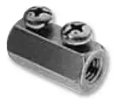
Connecting Nut, M6
- Manufacturer: OMRON INDUSTRIAL AUTOMATION
- Product type: Controller Accessories
- Current Rating:-; Product Range:-; Accessory Type:Electrode Connector; External Width:11.5mm; For Use With:Conductive Level Controllers; Length:20mm
- Product Range: -
- Current Rating: -
| Delivery and price | |
|---|---|
| Units per pack | 20 |
| Price | 3.19 € |
| Current stock | 10+ |
| Lead time | 30 days |
## **Conductive Level Controller**

## **61F-GP-N8**

## **Compact Plug-in Level Controllers for Single or Two-point Level Control of Conductive Materials (Liquids and Solids)**

Wide range of models: long-distance, high and low-sensitivity, and two-wired types available.

- 24/100/110/120/200/220/230/240 VAC operation possible.

Easy installation on DIN track.

Low-voltage (AC) electrodes.

Red LED operation indicator provided.

Conforms to EMC and LVD Directives.

## RC

UL/CSA approved.

## ~~Ordering Information~~

## **Model Number Legend:**

## **61F-GP-N8** j

1 2 3

**1. Plug-in Type**

**2. Compact 8-pin Type**

**3. Applications**

None: General-purpose type

- L: Long-distance type

H: High-sensitivity type (reverse acting) HY: High-sensitivity type (standard acting) D: Low-sensitivity type

R: Two-wired type

## **Accessories (Order Separately) Selection Guide for Electrode Holders and Separators**

## **Electrode Holders**

|**Applications**|**Applications**|For city water and<br>other general-use<br>electrodes. Easy-to-<br>replace separate<br>versions facilitate<br>maintenance of elec-<br>trodes.|When mounting space<br>is limited. Special 3-pole<br>holder of small size and<br>light weight. Ideal for<br>soft drink vendors, etc.,<br>where only limited<br>space is available.|For low specific liquids. Used for sew-<br>age, sea water, etc., having a low spe-<br>cific resistance. In sewage use, elec-<br>trode holders must be installed 10 to<br>20 cm apart from one another. For<br>acids, alkalis and sea water, electrode<br>holders may be as much as 1 meter<br>apart to operate properly.|When resistance to<br>high pressure is re-<br>quired. Ideal for use<br>in tanks where tem-<br>perature or pressure<br>inside the tank is<br>high, e.g. 250°C|
|---|---|---|---|---|---|
|**Mounting style**||Flange|Screw|Flange|Screw|
|**Insulator material**||Phenol resin|Phenol resin|Ceramics|Teflon|
|**Max. temperature**||70°C||150°C (without water drips or vapor on<br>the surface of the electrode holder)|250°C (without water<br>drips or vapor on the<br>surface of the<br>electrode holder)|
|**No. of**<br>**electrodes**|**1**|---|---|BF-1|BS-1|
||**3**|PS-3S|PS-31|---|---|


**Electrode Separators**

**No. of electrodes Model** 1 F03-14 1P 3 F03-14 3P ~~a~~

1

~~**61F-GP-N8**~~

~~**61F-GP-N8**~~

## **Selection Guide for Electrodes, Connecting, and Lock Nuts**

|**Applicable liquids**|**Material**|**Models for individual electrode assembly components**|**Models for individual electrode assembly components**|**Models for individual electrode assembly components**|**Models for individual electrode assembly components**|**Models for individual electrode assembly components**|**Models for individual electrode assembly components**|
|---|---|---|---|---|---|---|---|
|||**Electrode (1m long)**||**Connecting nut**||**Lock nut**||
|||**Model**|**Indication**<br>**mark**|**Model**|**Inscription**|**Model**|**Inscription**|
|**Purified city water,**<br>**industrial water,**<br>**sewage**|**Equivalent**<br>**to SUS 304**<br>**(AISI-304)**|F03-01 SUS201|1 line|F03-02 SUS201|---|F03-03 SUS201|---|
|**Purified city water,**<br>**industrial water,**<br>**sewage, dilute alka-**<br>**line solution**|**SUS316**<br>**(AISI-316)**|F03-01 SUS316|2 lines|F03-02 SUS316|6|F03-03 SUS316|6|


## ~~Specifications~~

|~~p~~<br>**Model/Items**<br>**General-purpose**<br>**Controller**<br>**61F-GP-N8**<br>**Long-distance**<br>**Controllers**<br>**61F-GP-N8L 2KM**<br>**(for 2 km)**<br>**61F-GP-N8L 4KM**<br>**(for 4 km)**<br>**High-sensitivity**<br>**Controllers**<br>**61F-GP-N8H**<br>**61F-GP-N8HY**<br>**(see note 1)**<br>**Low-sensitivity**<br>**Controller**<br>**61F-GP-N8D**<br>**Two-wired**<br>**Controller**<br>**61F-GP-N8R**|~~p~~<br>**Model/Items**<br>**General-purpose**<br>**Controller**<br>**61F-GP-N8**<br>**Long-distance**<br>**Controllers**<br>**61F-GP-N8L 2KM**<br>**(for 2 km)**<br>**61F-GP-N8L 4KM**<br>**(for 4 km)**<br>**High-sensitivity**<br>**Controllers**<br>**61F-GP-N8H**<br>**61F-GP-N8HY**<br>**(see note 1)**<br>**Low-sensitivity**<br>**Controller**<br>**61F-GP-N8D**<br>**Two-wired**<br>**Controller**<br>**61F-GP-N8R**|~~p~~<br>**Model/Items**<br>**General-purpose**<br>**Controller**<br>**61F-GP-N8**<br>**Long-distance**<br>**Controllers**<br>**61F-GP-N8L 2KM**<br>**(for 2 km)**<br>**61F-GP-N8L 4KM**<br>**(for 4 km)**<br>**High-sensitivity**<br>**Controllers**<br>**61F-GP-N8H**<br>**61F-GP-N8HY**<br>**(see note 1)**<br>**Low-sensitivity**<br>**Controller**<br>**61F-GP-N8D**<br>**Two-wired**<br>**Controller**<br>**61F-GP-N8R**|~~p~~<br>**Model/Items**<br>**General-purpose**<br>**Controller**<br>**61F-GP-N8**<br>**Long-distance**<br>**Controllers**<br>**61F-GP-N8L 2KM**<br>**(for 2 km)**<br>**61F-GP-N8L 4KM**<br>**(for 4 km)**<br>**High-sensitivity**<br>**Controllers**<br>**61F-GP-N8H**<br>**61F-GP-N8HY**<br>**(see note 1)**<br>**Low-sensitivity**<br>**Controller**<br>**61F-GP-N8D**<br>**Two-wired**<br>**Controller**<br>**61F-GP-N8R**|~~p~~<br>**Model/Items**<br>**General-purpose**<br>**Controller**<br>**61F-GP-N8**<br>**Long-distance**<br>**Controllers**<br>**61F-GP-N8L 2KM**<br>**(for 2 km)**<br>**61F-GP-N8L 4KM**<br>**(for 4 km)**<br>**High-sensitivity**<br>**Controllers**<br>**61F-GP-N8H**<br>**61F-GP-N8HY**<br>**(see note 1)**<br>**Low-sensitivity**<br>**Controller**<br>**61F-GP-N8D**<br>**Two-wired**<br>**Controller**<br>**61F-GP-N8R**|~~p~~<br>**Model/Items**<br>**General-purpose**<br>**Controller**<br>**61F-GP-N8**<br>**Long-distance**<br>**Controllers**<br>**61F-GP-N8L 2KM**<br>**(for 2 km)**<br>**61F-GP-N8L 4KM**<br>**(for 4 km)**<br>**High-sensitivity**<br>**Controllers**<br>**61F-GP-N8H**<br>**61F-GP-N8HY**<br>**(see note 1)**<br>**Low-sensitivity**<br>**Controller**<br>**61F-GP-N8D**<br>**Two-wired**<br>**Controller**<br>**61F-GP-N8R**|
|---|---|---|---|---|---|
|**Controlling materials**<br>**and operating**<br>**conditions**|For control of ordi-<br>nary purified water<br>or sewage water|For control of ordi-<br>nary purified water<br>in cases where the<br>distance between<br>sewage pumps and<br>water tanks or be-<br>tween receiver<br>tanks and supply<br>tanks is long or<br>where remote con-<br>trol is required.|For control of liq-<br>uids with high spe-<br>cific resistance<br>such as distilled<br>water|For control of liq-<br>uids with low spe-<br>cific resistance<br>such as salt water,<br>sewage water, acid<br>chemicals, alkali<br>chemicals|For control of ordi-<br>nary purified water<br>or sewage water<br>used in combina-<br>tion with two-wired-<br>type electrode<br>holder (incorporat-<br>ing a resistor of<br>6.8 kΩ)|
|**Supply voltage**|24, 100, 110, 120, 200, 220, 230 or 240 VAC; 50/60 Hz|||||
|**Operating voltage range**|85% to 110% of rated voltage|||||
|**Interelectrode voltage**|8 VAC||24 VAC|8 VAC||
|**Interelectrode current**|Approx. 1 mA AC max.||Approx.<br>0.4 mA AC max.|Approx. 1 mA AC max.||
|**Power consumption**|Approx. 3.5 VA max.|||||
|**Interelectrode operate**<br>**resistance**|Approx. 0 to 4 kΩ|Approx. 0 to 1.3 kΩ<br>(for 2 km)<br>Approx. 0 to 0.5 kΩ<br>(for 4 km)|Approx. 15 kΩto<br>70 kΩ<br>(see note 3)|Approx. 0 to 1.3 kΩ|Approx. 0 to 2 kΩ|
|**Interelectrode release**<br>**resistance**|Approx. 15 k to<br>∞Ω|Approx. 4 k to∞Ω<br>(for 2 km)<br>Approx. 0.5 k to<br>∞Ω(for 4 km)|Approx. 300 k to<br>∞Ω|Approx. 4 k to∞Ω|Approx. 15 k to<br>∞Ω|
|**Response time**|Operate: 80 ms max.<br>Release: 160 ms max.|||||
|**Cable length**<br>**(see note 2)**|1 km max.|2 km max.<br>4 km max.|50 m max.|1 km max.|800 m max.|
|**Control output**|1 A, 250 VAC (Inductive load: cosφ= 0.4)<br>3 A, 250 VAC (Resistive load)|||||
|**Ambient temperature**|Operating:<br>--10°C to 55°C|||||
|**Ambient humidity**|Operating:<br>45% to 85% RH|||||
|**Insulation resistance**<br>**(see note 3)**|100 MΩmax. (at 500 VDC)|||||
|**Dielectric strength**<br>**(see note 4)**|2000 VAC, 50/60 Hz for 1 min.|||||
|**Life expectancy**|Electrical:<br>100,000 operations min.<br>Mechanical: 5,000,000 operations min.|||||


**Note:** 1. The relay in the 61F-GP-N8H de-energizes when there is water present across the electrodes, whereas the relay in the 61F-GPN8HY energizes when there is water present across the electrodes.

2

~~**61F-GP-N8 61F-GP-N8**~~

2. The length when using completely-insulated, 600-V, 3-conductor (0.75 mm[2] ) cabtire cables. Usable cable lengths will become shorter as the cable diameter or number of conductors becomes larger.

3. The insulation resistance and dielectric strength indicate values between power terminals and electrode terminals, between power terminals and contact terminals, and between electrode terminals and contact terminals.

4. Possible to use with 10 kΩ or less, however, this may cause reset failure.

## **Internal Circuit Diagrams**

**==> picture [469 x 110] intentionally omitted <==**

**----- Start of picture text -----**<br>
61F-GP-N8/-N8L/-N8D/-N8HY 61F-GP-N8H 61F-GP-N8R<br>Power Power Power<br>supply 24 V supply 24 V supply 24 V<br>Control circuit Control circuit Control circuit<br>8 V<br>8 V (see note) 24 V<br>2<br>**----- End of picture text -----**<br>


**==> picture [209 x 8] intentionally omitted <==**

**----- Start of picture text -----**<br>
61F-GP-N8/-N8L/-N8D/-N8HY 61F-GP-N8H<br>**----- End of picture text -----**<br>


**Note:** 24 V for the 61F-GP-N8HY.

## ~~Connections~~

## **Automatic Water Supply and Drainage Control**

1. Water Supply

- Connect electromagnetic switch coil terminal A to terminal 2.

- The pump stops when the water level reaches E1 and starts when the water level drops below E2.

2. Drainage

- Connect the electromagnetic switch coil terminal A to terminal 3.

- The pump starts when the water level reaches E1 and stops when the water level drops below E2.

**==> picture [283 x 271] intentionally omitted <==**

**----- Start of picture text -----**<br>
200-VAC power supply 61F-GP-N8<br>MCCB<br>0 V 8 V<br>200 V 24 V Control circuit<br>roe<br>(See note 1<br>below.)<br>tLO OO ©<br>es oe<br>Contactor<br>(See note 2<br>Lt | below.) ci} [4 PS-3S<br>Stop<br>THR<br>HE Start<br>Tank<br>Reservoir<br>eee<br>**----- End of picture text -----**<br>


- **Note:** 1. The diagram shows the connections for water supply. When draining, change the connection from terminal 2 to terminal 3. 2. The earth terminal must be earthed.

3

~~——~~ ~~**61F-GP-N8** ——_—_—_—_—~~ ~~**61F-GP-N8**~~

## ~~Operation~~

The Conductive Level Controller consists of a plug-in controller connected to a set of stainless steel probes. These are cut to length and inserted vertically into the liquid. A low voltage is applied between these probes and the earth probe (or tank, if it is electrically conductive). The water provides a current between the earth probe and the high-level probe. The output relay in the Controller is energized when the water level reaches the high-level probe and de-energized when the water level falls below it.

For two-point control a low-level probe is used as well. In this case the relay does not de-energize until the water level falls below the low-level probe. Using the low-level probe allows a wide differential between switching a pump on and off, and can avoid excessive pump operation during tank emptying or filling. If this differential is not required, the low-level probe need not be connected.

## ~~Surge Suppressor Unit (61F-03B/04B)~~

3. When connecting the Surge Suppressor Unit, wire as shown in the following example (with three electrodes).

A high-capacity protective device is available which protects 61F-series Floatless Level Controllers against faults arising from electrical surges (such as indirect strokes of lightning) when the Controllers are employed in elevated water tanks or in high-altitude locations.

**Specifications Discharge start voltage** 90 V ±20 VDC **Impulse withstand voltage** 200,000 V (1 x 40 µs) **Impulse withstand current** 6,000 A (1 x 40 µs) ~~_—~~ **Internal Connections**

**==> picture [179 x 93] intentionally omitted <==**

**----- Start of picture text -----**<br>
61F-03B<br>Fe<br>Ground<br>Ground {Fe<br>bey<br>E1<br>E2<br>E3<br>**----- End of picture text -----**<br>


**61F-03B 61F-04B** Oo @ @ @ @ Od © O@ & O® @& ~~rL~~

**Connection Sockets** PF113A-E Track-mounted Socket PL11 Back-connecting Socket

## **Precautions**

1. Mount the Surge Suppressor Unit as close to the Controller as possible.

2. When grounding the Surge Suppressor Unit in the vicinity of the Controller, connect the ground side of the Surge Suppressor Unit to electrode E3.

**==> picture [139 x 77] intentionally omitted <==**

**----- Start of picture text -----**<br>
Long distance<br>61F-03B<br>Eales<br>Ground<br>**----- End of picture text -----**<br>


4

~~——~~ ~~**61F-GP-N8 61F-GP-N8**~~

## ~~Dimensions~~

**Note:** All units are in millimeters unless otherwise indicated.

**==> picture [72 x 61] intentionally omitted <==**

**----- Start of picture text -----**<br>
61F-GP<br>-N8<br>91<br>eet<br>PF083A-E<br>**----- End of picture text -----**<br>


## **Electrode Holders**

**==> picture [30 x 9] intentionally omitted <==**

**----- Start of picture text -----**<br>
PS-3S<br>**----- End of picture text -----**<br>


**==> picture [443 x 325] intentionally omitted <==**

**----- Start of picture text -----**<br>
PF2 parallel thread<br>9-dia. rubber (effective dia.: 58.135) PS-3S/-3SR PS-4S/-4SR PS-5S/-5SR<br>bushing (inner) 34 dia.<br>E2<br>E3 E2 E3 E2<br>80 92<br>E1<br>E1 E1<br>E3 E4 E4<br>13 26 80<br>40<br>20<br>Mounting Holes Screw Holes<br>Used with coupling Used with mounting bracket<br>c ?<br>PF2 65-dia. hole<br>c M 4<br>PF1/2 Parallel thread<br>38.5<br>11 32 11 dia.<br>7 12 Mounting Holes<br>4 dia. PF1/2<br>Electrode Rubber<br>SUS304 / 3 packing 26 -<br>M3<br>(see note) 29.5 dia.<br>Dust preventive rubber cap (optional)<br>Note: Standardholderconstructionincludesthreeintegral 300-mm-longelec-<br>trodes. However, a model having 1,000-mm-long electrodes is avail-<br>able on request.<br>**----- End of picture text -----**<br>


**==> picture [29 x 9] intentionally omitted <==**

**----- Start of picture text -----**<br>
PS-31<br>**----- End of picture text -----**<br>


**==> picture [24 x 8] intentionally omitted <==**

**----- Start of picture text -----**<br>
BF-1<br>**----- End of picture text -----**<br>


**==> picture [277 x 106] intentionally omitted <==**

**----- Start of picture text -----**<br>
Terminal bolt Cast iron<br>SUS201 (M6) Two M5 x 25<br>mounting<br>Nut (M6) screws 26-dia. hole<br>LS 48<br>60 48 33<br>dia.<br>\@ C=) 20 dia.<br>ey (ie Two, 6-dia. holes<br>18<br>17 14 23<br>(49)<br>72<br>**----- End of picture text -----**<br>


5

~~**61F-GP-N8**~~

~~**61F-GP-N8**~~

## **BS-1**

**==> picture [239 x 82] intentionally omitted <==**

**----- Start of picture text -----**<br>
Terminal bolt Width across flats: 20 Two M4<br>SUS304 (M4) P=0.7 M18P = 1.5 P = 0.7<br>24 dia.<br>aa eon.<br>Nut (iron) 12 39 M18 P=1.5<br>50 51 (fine screw thread)<br>101<br>**----- End of picture text -----**<br>


## **Electrode Separators**

**==> picture [142 x 96] intentionally omitted <==**

**----- Start of picture text -----**<br>
F03-14 1P (for Single Pole)<br>6.5 dia.<br>4k<br>aOG 28 dia.<br>**----- End of picture text -----**<br>


## **F03-14 3P (for Three Poles)**

**==> picture [66 x 77] intentionally omitted <==**

**----- Start of picture text -----**<br>
Three, 7 dia.<br>|e<br>20<br>41 dia.<br>eS)ro<br>**----- End of picture text -----**<br>


## **Connecting Sockets**

## **Track Mounted Socket**

## **PF083A-E**

**==> picture [378 x 108] intentionally omitted <==**

**----- Start of picture text -----**<br>
Eight, M3.5 x 7sems screws Terminal Arrangement/ Mounting Holes<br>Internal Connections<br>Two, 4.2-dia.<br>holes (Top View)<br>52 max. 25 dia.<br>Two, M4 or 4.5-dia. holes<br>33 21 max. 9 OOG<br>41 max. | 35 a[<br>**----- End of picture text -----**<br>


## **Back Connecting Socket**

**==> picture [25 x 9] intentionally omitted <==**

**----- Start of picture text -----**<br>
PL08<br>**----- End of picture text -----**<br>


**==> picture [406 x 116] intentionally omitted <==**

**----- Start of picture text -----**<br>
Terminal arrangement/ Mounting Holes<br>Internal Connections<br>Two, 3.5-dia. or<br>(Bottom View) M3 Controller<br>mounting holes<br>Two, 3.5-dia. or M3<br>1 35 re co oy y<br>Two, 2-dia. holes socket mounting holes<br>50.5 max. 30 dia.<br>31-dia.<br>hole<br>35 max.<br>Approx. 20.5<br>iXG , |<br>**----- End of picture text -----**<br>


6

~~**61F-GP-N8**~~

~~**61F-GP-N8**~~

## **Holding Brackets**

To mount the 61F-GP-N8 Conductive Level Controller on the PF083A Track Mounted Socket, use the PFC-N8 Mounting Brackets attached to the Socket as an accessory.

## **PFC-N8**

**==> picture [22 x 12] intentionally omitted <==**

**----- Start of picture text -----**<br>
Approx.<br>80<br>**----- End of picture text -----**<br>


## **Surge Suppressor Unit**

**61F-03B 61F-04B**

**==> picture [24 x 68] intentionally omitted <==**

**----- Start of picture text -----**<br>
61F-03B<br>61F-04B<br>PF113A<br>**----- End of picture text -----**<br>


## ~~Precautions~~

## **How to Mount Electrodes**

## **Connecting Electrodes to Electrode Holders**

**==> picture [208 x 130] intentionally omitted <==**

**----- Start of picture text -----**<br>
Electrode holder<br>Clamp screw<br>Connecting nut 3. Tighten the electrode with<br>the two clamp screws.<br>1. Spin a lock nut and a spring<br>washer onto the electrode. Spring washer<br>4. Secure the connecting<br>nut by tightening the lock<br>ro ILJ| nut and spring washer.<br>Lock nut<br>2. Fully fit the electrode into the<br>Electrode connecting nut attached to theelectrode holder.<br>**----- End of picture text -----**<br>


## **Connecting One Electrode to Another**

**==> picture [165 x 131] intentionally omitted <==**

**----- Start of picture text -----**<br>
Electrode<br>Lock nut 2. Fully fit the<br>Spring washer electrode into the<br>CL) Connecting nut connecting nutattached to the<br>electrode holder.<br>Spring 3. Tighten the electrode with<br>washer the two clamp screws.<br>4. Secure the connecting<br>nut by tightening the lock<br>—~ id nut and spring washer.<br>1. Spin a lock nut and a spring<br>washer onto the electrode.<br>**----- End of picture text -----**<br>


7

~~**61F-GP-N8**~~

~~**61F-GP-N8**~~

## ~~Application Examples~~

- Level control in tanks, reservoirs, sewage plants, underground wells, mixing plants etc.

- Level control for element protection in pipes, channels, and irrigation systems.

- Flow detection in pipes, channels, and irrigation systems.

   - Dispensing of liquids by volume.

   - Indication of liquid buildup due to filter blockages.

   - Pollution/foul water detection for rivers, drains, etc.

   - Alarm control warning of abnormal or dangerously high or low levels.

- Ice bank control in cold drink dispensers, ice makers, water chillers, bulk milk tanks, etc.

## **Application**

When using electrodes in sea water or sewage, provide a sufficient interval (normally 1 m) between the electrodes. If the sufficient interval cannot be provided, employ a low-sensitivity-type Floatless Level Controller.

When taping one of the electrodes to prevent it from contacting the other electrodes in water, do not tape the electrode entirely but leave at least 100 mm of its end uncovered.

When the required length of the electrode is more than 1 m, use a separator at each joint of two electrodes so as to prevent the electrodes from contacting one another.

**Note:** Avoid use of the separators in dust-containing liquids.

Usually, electrodes are used in a set of three: long, medium, and short. Connect the short electrode to E1, the medium electrode to E2, and the long electrode to E3. Make E3 at least 50 mm longer than E2.

Note that the 61F-GP-N8 Conductive Level Controller is capable of controlling liquids with specific resistances of up to 30 kΩ-cm when the Controller employs a PS-3S electrode holder with the electrode(s) submerged to a depth of 30 mm max.

|**Kind of water**|**Specific**<br>**resistance**|**Applicable type**|
|---|---|---|
|**City water**|5 to 10 kΩ-cm|Standard type|
|**Well water**|2 to 5 kΩ-cm|Standard type|
|**Industrial water**|5 to 15 kΩ-cm|Standard type|
|**Rainwater**|15 to 25 kΩ-cm|Standard type|
|**Sea water**|0.03 kΩ-cm|Low-sensitivity type|
|**Sewage**|0.5 to 2 kΩ-cm|Low-sensitivity type|
||100 kΩ-cm or less|High-sensitivity type|


**==> picture [177 x 72] intentionally omitted <==**

**----- Start of picture text -----**<br>
E1<br>E2<br>Min<br>E3 50mm<br>1m 1m<br>**----- End of picture text -----**<br>


Electrodes are in actual contact with the liquid. Standard electrodes are made of stainless steel and usable in purified water, sea water, sewage, acid (except acetic acid, sulfuric acid, etc.) and alkaline liquids, although they may corrode depending upon the temperature and working conditions.

## **ALL DIMENSIONS SHOWN ARE IN MILLIMETERS.**

To convert millimeters into inches, multiply by 0.03937. To convert grams into ounces, multiply by 0.03527.

Cat. No. F43-E1-1A **In the interest of product improvement, specifications are subject to change without notice.**

## **OMRON Corporation**

Industrial Devices and Components Division H.Q. Supervisory Control Devices Division 28th Fl., Crystal Tower Bldg. 1-2-27, Shiromi, Chuo-ku, Osaka 540 Japan Printed in Japan Phone: 81-6-949-6035 Fax: 81-6-949-6069 1297-2M (1097)

8
Updated at April 22, 2026
With a legacy spanning over 80 years, Omron Industrial Automation is a globally recognized leader in the manufacture of advanced industrial control and automation components. Renowned for their reliability and engineering excellence, Omron delivers comprehensive solutions that enhance efficiency, machine safety, and precision across a wide range of manufacturing environments. Our extensive portfolio of Omron products is heavily focused on their industry-leading sensing and switching technologies. We offer a vast selection of sensors, excelling specifically in high-performance proximity sensors, light sensors, and temperature sensors. Complementing this range are robust switching solutions, featuring a deep inventory of power relays, solid-state relays, safety relays, and essential relay accessories designed for demanding operational requirements. Beyond sensing and switching, Omron is highly regarded for its precision automation and process control equipment. Our selection features highly accurate temperature controllers, versatile process controllers, and sophisticated panel displays and instrumentation. To support these fundamental systems, we also supply dependable Omron power supplies, notably AC/DC converters, alongside vital connectivity components like DIN rail terminal blocks to ensure secure, efficient, and complete industrial setups.
About Novapart
Novapart is a B2B electronic component broker specialising in stock shortages and cost reduction. We source hard-to-find parts and identify compliant alternatives across a catalogue of 410,000+ components from 500+ manufacturers.
Learn more →Stock Shortage Specialist
When a component is unavailable, discontinued or has an unacceptable lead time, we tap into our network of vetted European and Asian distributors to source what you need — without compromising on quality or traceability.
Request a quote →Compliant Alternatives
We identify pin-to-pin, electrically equivalent substitutes that meet the same certifications (RoHS, AEC-Q100, REACH) as your original specification — validated against datasheets, not just part numbers. Often at a lower cost.
BOM Analysis service →