
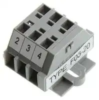


F03-20
Terminal Block, Liquid Leak Sensing Band, Nylon 6.6
- Manufacturer: OMRON INDUSTRIAL AUTOMATION
- Product type:
- SVHC: No SVHC (27-Jun-2024)
- For Use With: Liquid Leak Sensing Band
- Accessory Type: Terminal Block
| Delivery and price | |
|---|---|
| Units per pack | 50 |
| Price | 104.29 € |
| Current stock | 10+ |
| Lead time | 30 days |
**Sensing Band F03-15**
CSM_F03-15_DS_E_1_4
- Ideal for harsh electrical room environments that are dusty and humid.
- For installation in locations requiring insulated materials.
Indicates models that allow free cutting.
## **Orderin Information g**
|**Name**<br>**Model number**<br>**Remarks**<br>Liquid Leakage Sensing Band<br>**F03-15-1M**<br>Length: 1m<br>**F03-15-2M**<br>Length: 2m<br>**F03-15-5M**<br>Length: 5m<br>**F03-15-10M**<br>Length: 10m<br>**F03-15-15M**<br>Length: 15m<br>**F03-15-20M**<br>Length: 20m<br>**F03-15-25M**<br>Length: 25m<br>**F03-15-50M**<br>Length: 50m<br>**F03-15-75M**<br>Length: 75m<br>**F03-15-100M**<br>Length: 100m<br>SensingBand stickers<br>**F03-25**<br>30 Stickers per bag|**Name**<br>**Model number**<br>**Remarks**<br>Liquid Leakage Sensing Band<br>**F03-15-1M**<br>Length: 1m<br>**F03-15-2M**<br>Length: 2m<br>**F03-15-5M**<br>Length: 5m<br>**F03-15-10M**<br>Length: 10m<br>**F03-15-15M**<br>Length: 15m<br>**F03-15-20M**<br>Length: 20m<br>**F03-15-25M**<br>Length: 25m<br>**F03-15-50M**<br>Length: 50m<br>**F03-15-75M**<br>Length: 75m<br>**F03-15-100M**<br>Length: 100m<br>SensingBand stickers<br>**F03-25**<br>30 Stickers per bag|**Name**<br>**Model number**<br>**Remarks**<br>Liquid Leakage Sensing Band<br>**F03-15-1M**<br>Length: 1m<br>**F03-15-2M**<br>Length: 2m<br>**F03-15-5M**<br>Length: 5m<br>**F03-15-10M**<br>Length: 10m<br>**F03-15-15M**<br>Length: 15m<br>**F03-15-20M**<br>Length: 20m<br>**F03-15-25M**<br>Length: 25m<br>**F03-15-50M**<br>Length: 50m<br>**F03-15-75M**<br>Length: 75m<br>**F03-15-100M**<br>Length: 100m<br>SensingBand stickers<br>**F03-25**<br>30 Stickers per bag|
|---|---|---|
|**Name**|**Model number**|**Remarks**|
|Liquid Leakage Sensing Band<br>**F03-15-1M**<br>**F03-15-2M**<br>**F03-15-5M**<br>**F03-15-10M**<br>**F03-15-15M**<br>**F03-15-20M**<br>**F03-15-25M**<br>**F03-15-50M**<br>**F03-15-75M**<br>**F03-15-100M**|**F03-15-1M**|Length: 1m|
||**F03-15-2M**|Length: 2m|
||**F03-15-5M**|Length: 5m|
||**F03-15-10M**|Length: 10m|
||**F03-15-15M**|Length: 15m|
||**F03-15-20M**|Length: 20m|
||**F03-15-25M**|Length: 25m|
||**F03-15-50M**|Length: 50m|
||**F03-15-75M**|Length: 75m|
||**F03-15-100M**|Length: 100m|
|SensingBand stickers<br>**F03-25**|**F03-25**|30 Stickers per bag|
**Note: 1.** Specify the cable length for F03-15 from the list above.
**2.** The cables can be cut.
## **S ecifications p**
|**Specifications**||
|---|---|
|**Sheath**|Flexible, transparent vinyl chloride|
|**Core**|SUS304 stainless steel|
|**Ambient operating temperature**|15 to 50C|
|**Weight**|Approx. 48g(1 m)|
## **Dimensions (Unit: mm)**
## ■ **Sensing Band**
**==> picture [178 x 15] intentionally omitted <==**
**----- Start of picture text -----**<br>
■ Sensing Band Stickers<br>**----- End of picture text -----**<br>
**==> picture [509 x 99] intentionally omitted <==**
**----- Start of picture text -----**<br>
Appearance F03-25<br>Appearance<br>a |=<br>Structure Electrode pairs (Stainless steel wire0.3 mm x 12-wire braided cable) Structure [}——_ 25±2 — l _—— (0.5)<br>(5)<br>8<br>(3) p 15 T ±1 Pt<br>[8 [Beeee] =e< ea 25 Flexible, transparentvinyl chloride === Pas Adhesive tape (1)<br>i 333 (3 pairs/m) to Material: SUS304<br>**----- End of picture text -----**<br>
**1** ~~a~~
**F03-15**
## **Chemical Resistivit for F03-16PE/-16PT y**
|**Material**<br>~~————_————~~<br>~~po~~|**Sheath**<br>~~————_————~~<br>~~ee~~<br>~~ee~~|**Sheath**<br>~~————_————~~<br>~~ee~~<br>~~ee~~|**Core**<br>~~————_————~~<br>~~ee~~|**Material**<br>~~ee~~|**Sheath**<br>~~ee~~<br>~~ee~~<br>~~ee~~|**Sheath**<br>~~ee~~<br>~~ee~~<br>~~ee~~|**Core**<br>~~ee~~<br>~~ee~~<br>~~ee~~|
|---|---|---|---|---|---|---|---|
||**Polyethylene**<br>~~————_————~~<br>~~ee~~|**Fluoroplastic**<br>~~————_————~~<br>~~ee~~|**SUS316**<br>~~————_————~~<br>~~ee~~||**Polyethylene**<br>~~ee~~<br>~~ee~~|**Fluoroplastic**<br>~~ee~~<br>~~ee~~<br>~~ee~~|**SUS316**<br>~~ee~~<br>~~ee~~<br>~~ee~~|
|**Water**<br>~~————_————~~<br>~~po~~<br>~~po~~|A<br>~~————_————~~<br>~~ee~~|A<br>~~————_————~~<br>~~ee~~|A<br>~~————_————~~<br>~~ee~~|**Toluene**<br>~~ee~~|C<br>~~ee~~<br>~~ee~~|B<br>~~ee~~<br>~~ee~~<br>~~ee~~|B<br>~~ee~~<br>~~ee~~<br>~~ee~~|
|**Acetone**<br>~~po~~<br>~~po~~<br>~~po~~|C|A|A|**Phenol**|B|B<br>~~ee~~|A<br>~~ee~~|
|**Ammonia**<br>~~po~~<br>~~po~~<br>~~po~~|A|A|A|**Butanol**|B|A|---|
|**Ethanol**<br>~~po~~<br>~~po~~<br>~~po~~|B|A|A|**Fluorine**|A|A|C|
|**Hydrochloric acid**<br>~~po~~<br>~~po~~<br>~~po~~|A|A|C|**Hexane**|C|A|---|
|**Hydrogenperoxide solution**<br>~~po~~<br>~~po~~<br>~~po~~|A|A|A|**Benzene**|C|A|A|
|**Xylene**<br>~~po~~<br>~~po~~<br>~~**p**o~~|B|A|A|**Methanol**|B|A|A|
|**Cyclohexane**<br>~~po~~<br>~~**p**o~~|C|A|---|**Sulfuric acid**|C|A|B|
|**Trichloroethylene**<br>~~**p**o~~|C|A|A<br>~~o~~|**Phosphoric acid** <br>~~o~~|A<br>~~o~~|B<br>~~o~~|B<br>~~o~~|
- **Note: 1.** A: Not affected at all or only very slightly affected.
- B: Slightly affected but, depending on the conditions, sufficient for use.
- C: Affected but may still be used. (Replace the Sensing Band immediately after detection.)
**2.** The F03-16PE Sensing Band is made from the following materials. Core: SUS316 Insulated sheath: Polyethylene
**3.** In order to prevent secondary fire damage, consider the effect of the atmosphere of the environment and the solution to be detected on the Sensing Band.
**4.** If the Sensing Band changes shape or color when a liquid is detected, replace the Sensing Band.
## **Connectin the Sensin Band g g**
## **Bending the Sensing Band**
To change the direction of the Sensing Band, bend the Sensing Band in one or two places where the core is not exposed.
**==> picture [117 x 8] intentionally omitted <==**
**----- Start of picture text -----**<br>
Bent in 1 place Bent in 2 places<br>**----- End of picture text -----**<br>
- **Note:** Bend the Sensing Band approximately 4 cm (i.e., twice the distance between places where the core is exposed) away from places where a Sticker is attached. If the Sensing Band is bent at places further away than this, the Sensing Band may come away from the surface.
## **Stripping and Connecting Terminals**
**1.** Cut into the Sensing Band approximately 4 to 6 cm in from the end as shown in the diagram below.
## **Interval Between Stickers**
When securing the Sensing Band with Stickers, attach the Stickers at intervals of 20 to 30 cm in places where the core is not exposed.
Sensing 20 to 30 cm Band “ Sticker **Note: 1.** When using the F03-26PES (adhesive-tape model), be sure to wipe all moisture, oil, and dust from the surface to which << ———| , the Sticker is to be attached. Failure to do so may result in insufficient adhesion, and the Sticker may peel away from the surface.
**2.** When using the F03-26PEN (screw model), before installing the Sensing Band, it is necessary to perform stud welding. For details on the pitch of the studs, refer to the information on the dimensions of Sensing Band Stickers.
**3.** Commercially available screwdrivers can be used. It is recommended, however, that either a 210-350/01 screwdriver or a 209-132 operating tool to connect jumpers, both manufactured by Wago Japan, is used. Contact http://www.wago.com.
**2.** Strip away approximately the last 9 mm of the sheath to expose the core (SUS line).
**3.** To connect to the Terminal Block, insert the screwdriver (see note 3) from the top of the Terminal Block and insert the stripped end of the core from the side. (Refer to _Dimensions_ on page 1.)
**==> picture [184 x 42] intentionally omitted <==**
**----- Start of picture text -----**<br>
4 to 6 cm Insert<br>9 mm > le ~<br>F03-20<br>Terminal<br>Exposed Block<br>part of<br>core<br>**----- End of picture text -----**<br>
**Note:** Check that the wiring is secure before using the K7L in applications.
**2**
**F03-15**
## **Li uid Leaka e Sensin Band Precautions q g g**
Refer to the following installation methods and install the Sensing Band securely using the proper method for the location and environment.
**1.** Post or Beam Mounting
Use fasteners, such as concrete anchors, to secure the Sensing Band every 500 to 1,000 mm to ensure that it does not come loose. If the surface of the post or beam is very uneven, apply two-sided tape to the mounting surface first and then secure the Sensing Band to the tape with the fastener.
**2.** Conduit Installation
- For vertical conduits, wrap the Sensing Band around the conduit at a pitch 2 to 3 times the diameter of the conduit. For horizontal conduits, secure the Sensing Band at appropriate intervals along the bottom of the conduit using an insulated adhesive strap, such as Insulock, to ensure that the Sensing Band does not come loose.
**3.** Dike and Catch Basin installation
Use the specified stickers (sold separately) to secure the Sensing Band at appropriate intervals to keep it flat in the dike or catch basin.
**4.** Floor Installation
Estimate the leakage detection area and use stickers to secure the Sensing Band at appropriate intervals on the floor and around equipment. Cover the Sensing Band with plastic or metal molding to protect it from contact with other objects and from being stepped on by workers. Leave a 50- to 100-mm gap in the molding at approximately 500-mm intervals where it touches the floor to allow liquids to pass through.
**5.** Do not install the Sensing Band in locations where condensation is likely to occur.
**6.** Mount the Sensing Band as close as possible to the mounting surface. Make sure that any gaps are no more than 2 mm in horizontal installations, such as the floor, and no more than 1 mm with vertical installations, such as posts and beams.
**7.** Attach an insulated protector, such as plastic molding, securely to the Sensing Band to protect it from contact with power cables carrying over 300 V.
**8.** Normally leaking materials detected by the Sensing Band will evaporate and the Sensing Band will return to its original state. The Sensing Band may not return to its original state and will have to be replaced, however, if the leaking material contained conductive impurities. Follow the appropriate replacement procedures.
**9.** The Sensing Band is not designed to be used as electrical wiring and must not be used for any purpose other than leak detection.
**10.** Do not apply petroleum-based products, such as wax, to the Sensing Band. Otherwise, liquids may be repelled and detection may fail.
## **Dimensions (Unit: mm)**
## **Liquid Leakage Point Sensor**
**F03-16PS F03-16PS-F**
**==> picture [498 x 168] intentionally omitted <==**
**----- Start of picture text -----**<br>
10 8<br>2<br>Overall length Electrode<br>2,000 mm<br>Sheath: Fluoroplastic, 0.66 dia.<br>32 dia. 5.5 dia.<br>2.6-dia. vinyl-insulated round cable with Conductor cross section:<br>2 conductors, 0.079 mm [2]<br>**----- End of picture text -----**<br>
**Note: 1.** The Terminal Block is made of nylon 66. Mount the Terminal Block in locations not subject to liquid chemicals using M3 screws. **2.** Secure the Sockets with M3 screws at a torque of 0.78 to 1.18 N⋅m.
**3**
**F03-15**
## **Point Sensor Mounting Bracket**
## **F03-26PS**
**==> picture [503 x 188] intentionally omitted <==**
**----- Start of picture text -----**<br>
R5<br>10 19.2<br>1<br>8.85 3<br>24 1<br>R3<br>22.5 12<br>6 dia. Bonding plane (See note.)<br>Note: Use a polyvinyl chloride adhesive (commercially<br>available). No adhesive tape is used for mounting.<br>**----- End of picture text -----**<br>
**4**
**F03-15**
## **FAQs**
Some questions that are frequently asked about the K7L are given below. Use this information when selecting a model.
## **Can one K7L Amplifier be used for detection in more than one place?**
## **Yes.**
By using Terminal Blocks to connect Sensing Bands in parallel, detection can be performed in more than place with only one K7L Amplifier.
**==> picture [202 x 48] intentionally omitted <==**
**----- Start of picture text -----**<br>
Total: 400 m max.<br>, Terminal BlocksTerminal Block ee.<br>K7L-U<br>**----- End of picture text -----**<br>
## **Can a different terminal block (e.g. a commercially available terminal block or a terminal block constructed by the user) be used instead of the one provided?**
## **Yes.**
When using another terminal block, however, be sure to check that all the terminals are mutually isolated, and that there is no danger of ground faults in connecting cables or Sensing Bands.
## **Can the K7L Amplifier detect pure water?**
## **Yes.**
- **Note: 1.** When wiring, be sure not to exceed the maximum possible wiring distances for both the connecting cable and the Sensing Band. Exceeding these distances may lead to faulty operation. Connect one Sensing Band to each Terminal Block.
**2.** Not applicable to the K7L-UD.
## **Can the K7L Amplifier be used as a replacement for the 61F-GPN-V50 Water Leakage Detector?**
Even pure water, which has a resistance exceeding 10 MΩ⋅cm, can nearly always be detected if the K7L is used at its maximum sensitivity. This is because impurities are mixed with the water when it is leaked and the resistance drops.
**==> picture [71 x 19] intentionally omitted <==**
**----- Start of picture text -----**<br>
Pure water<br>Impurities<br>in the air<br>**----- End of picture text -----**<br>
## **Yes.**
Because the surge withstand capability is different, however, do not use in locations where it will be exposed to impulses and surges, such as outdoor roofs or in pump panels. Also, items such as the power supply voltage and the connection sockets are different. Check these items before application.
## **Can the K7L Amplifier detect oil?**
## **No.**
ALL DIMENSIONS SHOWN ARE IN MILLIMETERS.
In the interest of product improvement, specifications are subject to change without notice.
To convert millimeters into inches, multiply by 0.03937. To convert grams into ounces, multiply by 0.03527.
**5**
## Terms and Conditions Agreement
## Read and understand this catalog.
Please read and understand this catalog before purchasing the products. Please consult your OMRON representative if you have any questions or comments.
## Warranties.
(a) Exclusive Warranty. Omron’s exclusive warranty is that the Products will be free from defects in materials and workmanship for a period of twelve months from the date of sale by Omron (or such other period expressed in writing by Omron). Omron disclaims all other warranties, express or implied.
(b) Limitations. OMRON MAKES NO WARRANTY OR REPRESENTATION, EXPRESS OR IMPLIED, ABOUT NON-INFRINGEMENT, MERCHANTABILITY OR FITNESS FOR A PARTICULAR PURPOSE OF THE PRODUCTS. BUYER ACKNOWLEDGES THAT IT ALONE HAS DETERMINED THAT THE
PRODUCTS WILL SUITABLY MEET THE REQUIREMENTS OF THEIR INTENDED USE.
Omron further disclaims all warranties and responsibility of any type for claims or expenses based on infringement by the Products or otherwise of any intellectual property right. (c) Buyer Remedy. Omron’s sole obligation hereunder shall be, at Omron’s election, to (i) replace (in the form originally shipped with Buyer responsible for labor charges for removal or replacement thereof) the non-complying Product, (ii) repair the non-complying Product, or (iii) repay or credit Buyer an amount equal to the purchase price of the non-complying Product; provided that in no event shall Omron be responsible for warranty, repair, indemnity or any other claims or expenses regarding the Products unless Omron’s analysis confirms that the Products were properly handled, stored, installed and maintained and not subject to contamination, abuse, misuse or inappropriate modification. Return of any Products by Buyer must be approved in writing by Omron before shipment. Omron Companies shall not be liable for the suitability or unsuitability or the results from the use of Products in combination with any electrical or electronic components, circuits, system assemblies or any other materials or substances or environments. Any advice, recommendations or information given orally or in writing, are not to be construed as an amendment or addition to the above warranty.
See http://www.omron.com/global/ or contact your Omron representative for published information.
## Limitation on Liability; Etc.
OMRON COMPANIES SHALL NOT BE LIABLE FOR SPECIAL, INDIRECT, INCIDENTAL, OR CONSEQUENTIAL DAMAGES, LOSS OF PROFITS OR PRODUCTION OR COMMERCIAL LOSS IN ANY WAY CONNECTED WITH THE PRODUCTS, WHETHER SUCH CLAIM IS BASED IN CONTRACT, WARRANTY, NEGLIGENCE OR STRICT LIABILITY. Further, in no event shall liability of Omron Companies exceed the individual price of the Product on which liability is asserted.
## Suitability of Use.
Omron Companies shall not be responsible for conformity with any standards, codes or regulations which apply to the combination of the Product in the Buyer’s application or use of the Product. At Buyer’s request, Omron will provide applicable third party certification documents identifying ratings and limitations of use which apply to the Product. This information by itself is not sufficient for a complete determination of the suitability of the Product in combination with the end product, machine, system, or other application or use. Buyer shall be solely responsible for determining appropriateness of the particular Product with respect to Buyer’s application, product or system. Buyer shall take application responsibility in all cases.
NEVER USE THE PRODUCT FOR AN APPLICATION INVOLVING SERIOUS RISK TO LIFE OR PROPERTY OR IN LARGE QUANTITIES WITHOUT ENSURING THAT THE SYSTEM AS A WHOLE HAS BEEN DESIGNED TO ADDRESS THE RISKS, AND THAT THE OMRON PRODUCT(S) IS PROPERLY RATED AND INSTALLED FOR THE INTENDED USE WITHIN THE OVERALL EQUIPMENT OR SYSTEM.
## Programmable Products.
Omron Companies shall not be responsible for the user’s programming of a programmable Product, or any consequence thereof.
## Performance Data.
Data presented in Omron Company websites, catalogs and other materials is provided as a guide for the user in determining suitability and does not constitute a warranty. It may represent the result of Omron’s test conditions, and the user must correlate it to actual application requirements. Actual performance is subject to the Omron’s Warranty and Limitations of Liability.
## Change in Specifications.
Product specifications and accessories may be changed at any time based on improvements and other reasons. It is our practice to change part numbers when published ratings or features are changed, or when significant construction changes are made. However, some specifications of the Product may be changed without any notice. When in doubt, special part numbers may be assigned to fix or establish key specifications for your application. Please consult with your Omron’s representative at any time to confirm actual specifications of purchased Product.
## Errors and Omissions.
Information presented by Omron Companies has been checked and is believed to be accurate; however, no responsibility is assumed for clerical, typographical or proofreading errors or omissions.
**In the interest of product improvement, specifications are subject to change without notice.**
## **OMRON Corporation**
## **Industrial Automation Company**
2013.10
**http://www.ia.omron.com/**
(c)Copyright OMRON Corporation 2013 All Right Reserved.
Updated at June 9, 2026
With a legacy spanning over 80 years, Omron Industrial Automation is a globally recognized leader in the manufacture of advanced industrial control and automation components. Renowned for their reliability and engineering excellence, Omron delivers comprehensive solutions that enhance efficiency, machine safety, and precision across a wide range of manufacturing environments. Our extensive portfolio of Omron products is heavily focused on their industry-leading sensing and switching technologies. We offer a vast selection of sensors, excelling specifically in high-performance proximity sensors, light sensors, and temperature sensors. Complementing this range are robust switching solutions, featuring a deep inventory of power relays, solid-state relays, safety relays, and essential relay accessories designed for demanding operational requirements. Beyond sensing and switching, Omron is highly regarded for its precision automation and process control equipment. Our selection features highly accurate temperature controllers, versatile process controllers, and sophisticated panel displays and instrumentation. To support these fundamental systems, we also supply dependable Omron power supplies, notably AC/DC converters, alongside vital connectivity components like DIN rail terminal blocks to ensure secure, efficient, and complete industrial setups.
About Novapart
Novapart is a B2B electronic component broker specialising in stock shortages and cost reduction. We source hard-to-find parts and identify compliant alternatives across a catalogue of 410,000+ components from 500+ manufacturers.
Learn more →Stock Shortage Specialist
When a component is unavailable, discontinued or has an unacceptable lead time, we tap into our network of vetted European and Asian distributors to source what you need — without compromising on quality or traceability.
Request a quote →Compliant Alternatives
We identify pin-to-pin, electrically equivalent substitutes that meet the same certifications (RoHS, AEC-Q100, REACH) as your original specification — validated against datasheets, not just part numbers. Often at a lower cost.
BOM Analysis service →