
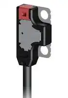


EX-Z11FB-P-R
Photoelectric Sensor, EX-Z Series, Ultra Miniature, Thru Beam, 50 mm, PNP, Dark On, Front Sensing
- Manufacturer: PANASONIC
- Product type:
- Sensing Range Max:50mm; Sensing Method:Through Beam; Sensor Output:PNP; Product Range:EX-Z Series; Connection Method:Cable; Supply Voltage DC Min:12V; Supply Voltage DC Max:24V; SVHC:No S
- SVHC: No SVHC (25-Jun-2025)
- Product Range: EX-Z Series
- Sensing Method: Through Beam
- Connection Method: Cable
- Sensing Range Max: 50mm
- Sensor Output Type: PNP
- Supply Voltage DC Max: 24V
- Supply Voltage DC Min: 12V
| Delivery and price | |
|---|---|
| Units per pack | 50 |
| Price | 64.92 € |
| Current stock | 10+ |
| Lead time | 30 days |
Amplifier Built-in

## Ultra-minute Photoelectric Sensor

EX-Z SERIES

Conforming to | EMC Directive CE | Wis Recognition ®

# The World’s No. 1 in Compactness

* Among photoelectric sensors with built-in amplifier, as of June 2015 (survey by our company)

(Actual size) —_—_$_—<$_$<—_$<—_$<_$<_$—_$—_$—_$—_$—_$—_—_—_—_—_————_ eel

2015.07

panasonic.net/id/pidsx/global

## **EX-Z SERIES** Ultra-minute Photoelectric Sensor **Amplifier Built-in** ~~thai~~ ede egg

## The World’s Smallest[*] Size

* Among photoelectric sensors with built-in amplifier, as of June 2015 (survey by our company)

##

##

## *** As compared to EX-10 series**

The world’s thinnest* sensor dimension of

3 mm 0.118 in has been achieved by utilizing new semiconductor packaging technology that does not use wire bonding. The small unit size allows installation of sensors in a narrow space where only a 4° conventional fiber sensor head could be installed before. The built-in amplifier also saves on installation space. * Among photoelectric sensors with built-in amplifier, as of June 2015 (survey by our company) **EX-Z13** □ Sensing range: 500 mm 19.685 in Repeatability: 0.05 mm 0.002 in or less Minimum sensing object: ø1.0 mm ø0.039 in opaque object ~~es~~ Front sensing type Side sensing type ~~—~~ **EX-Z12** □ ¥ Sensing range: 200 mm 7.874 in Repeatability: 0.03 mm 0.001 in or less **Approx. Approx.** Minimum sensing object: **50% smaller 35% smaller** ø0.5 mm ø0.020 in opaque object **in volume ratio in volume ratio than EX-10 than EX-10** ~~—~~ **EX-Z11** □ Y **EX-Z1** □ **F** □ **EX-Z1** □ Sensing range: 50 mm 1.969 in W8 × H14 × D3 mm W5.5 × H15.9 × D6.5 mm Repeatability: 0.02 mm 0.001 in or less W0.315 × H0.551 × D0.118 in W0.217 × H0.626 × D0.256 in Minimum sensing object: ø0.3 mm ø0.012 in opaque object

## **Small-object sensing capability**

## **Capable of sensing an extremely small ø0.3 mm** e **ø0.012 in object without slit** ~~T~~ **EX-Z11□**

A slit is provided on the front side of the main sensor body. The sensor can detect a ø0.3 mm ø0.012 in object (the smallest-object sensing capability in the industry*) without using an optional slit. * Among photoelectric sensors with built-in amplifier, as of June 2015 (survey by our company)

**Capability to sense a small ø1.0 mm ø0.039 in object** E **over long distance** ~~E~~ **EX-Z13□** She The high-brightness 4-element red LED provides strong light emission stably over a long period of time. In spite of the extremely small size, both front sensing and side sensing units can sense a small ø1.0 mm ø0.039 in object from a long distance of 500 mm 19.685 in. Since the spotlight is clearly visible, the sensing position can be easily confirmed.

**Clearly visible spotlight**

Sensing of end of thin pipe

Built-in slit **EX-Z11□** Slit diameter: 0.3 mm 0.012 in

2

## **A wide range of applications**

## **Inflection resistant cable type available for all models**

Inflection resistant cable type with improved flex resistance is available for all models. Select the model suitable for your specific application. The standard type comes with lead wires with the same diameter as previous models, but the outside diameter of the cable is 2.0 mm 0.079 in and thinner than the cables of  the **EX-10** series. This facilitates cable routing.

**==> picture [186 x 169] intentionally omitted <==**

**----- Start of picture text -----**<br>
Examples of applications<br>Ls».<br>Detection of parts in parts feeder<br>**----- End of picture text -----**<br>


## **IP67 protective structure** |

The sensors features an IP67 protective structure to allow their use in process lines where water is used or splashed. Rust-resistant stainless steel sensor mounting brackets and screws are available.

Note: If water splashes on the sensor during sensing operation, it may sense water as an object.

**==> picture [118 x 41] intentionally omitted <==**

**----- Start of picture text -----**<br>
IP67<br>(IEC)<br>(JTS<br>**----- End of picture text -----**<br>


## **Options**

**==> picture [160 x 19] intentionally omitted <==**

**----- Start of picture text -----**<br>
Detection of presence / absence of test<br>tube tray<br>**----- End of picture text -----**<br>


**A variety of mounting brackets are available!** | A spacer for mounting at the back (1 type) for through-wall sensing and sensor mounting brackets (3 types) are available to meet a diversity of sensor installation needs.

Spacer for mounting at the back Operation indicator (orange) can (for front sensing type only) be checked from the rear side. i. ~~-~~ a) Through-wall detection

**==> picture [89 x 7] intentionally omitted <==**

**----- Start of picture text -----**<br>
Detection of LED lead<br>**----- End of picture text -----**<br>


3

Ultra-minute Photoelectric Sensor **EX-Z SERIES**

## **ORDER GUIDE**

**==> picture [503 x 370] intentionally omitted <==**

**----- Start of picture text -----**<br>
Model No. (Note) Output<br>Type Appearance Sensing range<br>NPN output PNP output operation<br>EX-Z11FA EX-Z11FA-P Light-ON<br>50 mm 1.969 in<br>EX-Z11FB EX-Z11FB-P Dark-ON<br>EX-Z12FA EX-Z12FA-P Light-ON<br>200 mm 7.874 in<br>EX-Z12FB EX-Z12FB-P Dark-ON<br>EX-Z13FA EX-Z13FA-P Light-ON<br>500 mm 19.685 in<br>EX-Z13FB EX-Z13FB-P Dark-ON<br>EX-Z11FA-R EX-Z11FA-P-R Light-ON<br>50 mm 1.969 in<br>EX-Z11FB-R EX-Z11FB-P-R Dark-ON<br>EX-Z12FA-R EX-Z12FA-P-R Light-ON<br>200 mm 7.874 in<br>EX-Z12FB-R EX-Z12FB-P-R Dark-ON<br>EX-Z13FA-R EX-Z13FA-P-R Light-ON<br>500 mm 19.685 in<br>EX-Z13FB-R EX-Z13FB-P-R Dark-ON<br>EX-Z11A EX-Z11A-P Light-ON<br>50 mm 1.969 in<br>EX-Z11B EX-Z11B-P Dark-ON<br>EX-Z12A EX-Z12A-P Light-ON<br>200 mm 7.874 in<br>EX-Z12B EX-Z12B-P Dark-ON<br>EX-Z13A EX-Z13A-P Light-ON<br>500 mm 19.685 in<br>EX-Z13B EX-Z13B-P Dark-ON<br>EX-Z11A-R EX-Z11A-P-R Light-ON<br>50 mm 1.969 in<br>EX-Z11B-R EX-Z11B-P-R Dark-ON<br>EX-Z12A-R EX-Z12A-P-R Light-ON<br>200 mm 7.874 in<br>EX-Z12B-R EX-Z12B-P-R Dark-ON<br>EX-Z13A-R EX-Z13A-P-R Light-ON<br>500 mm 19.685 in<br>EX-Z13B-R EX-Z13B-P-R Dark-ON<br>Front sensing<br>Inflection resistant cable<br>Thru-beam<br>Side sensing<br>Inflection resistant cable<br>**----- End of picture text -----**<br>


Note: Mounting bracket is not supplied with the sensor. Please select from the range of optional sensor mounting brackets ( **MS-EXZ-□** ).

Note: The model No. with “ **E** ” shown on the label affixed to the thru-beam type sensor is the emitter, “ **D** ” shown on the label is the receiver.

## **OPTIONS**

**==> picture [395 x 127] intentionally omitted <==**

**----- Start of picture text -----**<br>
Designation Model No. Description<br>MS-EXZ-1 L-shaped mounting bracket (SUS304) for front sensing and side sensing types<br>(2 sets are required)<br>Sensor mounting  MS-EXZ-2 Mounting bracket (SUS304) for front sensing type<br>bracket (2 sets are required)<br>MS-EXZ-3 Mounting bracket (SUS304) for side sensing type<br>(2 sets are required)<br>Spacer for<br>mounting at the  MS-EXZ-4 Spacer for mounting at the back (polyacetal) for front sensing type<br>back<br>**----- End of picture text -----**<br>


## **Sensor mounting bracket**

**Spacer for mounting at the back**

**==> picture [505 x 109] intentionally omitted <==**

**----- Start of picture text -----**<br>
• MS-EXZ-1 • MS-EXZ-2 • MS-EXZ-3 • MS-EXZ-4<br>Material:  Stainless steel<br>(SUS304)   Material: Polyacetal<br>Two M2 (length 4 mm  Material:  Stainless steel  Material:  Stainless steel  M2 (length: 10 mm 0.394 in)<br>0.157 in) pan head screws  (SUS304)   (SUS304)  screws, nuts, spring<br>and two M2 (length 8 mm  Two M2 (length 4 mm  Two M2 (length 8 mm  washers and flat washers<br>0.315 in) pan head screws  0.157 in) pan head screws  0.315 in) pan head screws  are attached. (20 pieces<br>are attached.   are attached.   are attached.  each)<br>**----- End of picture text -----**<br>


4

Ultra-minute Photoelectric Sensor **EX-Z SERIES**

## **SPECIFICATIONS**

**==> picture [503 x 466] intentionally omitted <==**

**----- Start of picture text -----**<br>
Thru-beam<br>Type<br>Front sensing Side sensing Front sensing Side sensing Front sensing Side sensing<br>Model No. Light-ON EX-Z11FA ( -P )( -R ) EX-Z11A ( -P )( -R ) EX-Z12FA ( -P )( -R ) EX-Z12A ( -P )( -R ) EX-Z13FA ( -P )( -R ) EX-Z13A ( -P )( -R )<br>Item (Note 2) Dark-ON EX-Z11FB ( -P )( -R ) EX-Z11B ( -P )( -R ) EX-Z12FB ( -P )( -R ) EX-Z12B ( -P )( -R ) EX-Z13FB ( -P )( -R ) EX-Z13B ( -P )( -R )<br>Sensing distance 50 mm 1.969 in 200 mm 7.874 in 500 mm 19.685 in<br>ø0.3 mm ø0.012 in opaque object ø0.5 mm ø0.02 in opaque object ø1.0 mm ø0.039 in opaque object<br>(Completely beam interrupted object) (Completely beam interrupted object) (Completely beam interrupted object)<br>Minimum sensing object<br>Setting distance between emitter  Setting distance between emitter  Setting distance between emitter<br>and receiver: 50 mm 1.969 in and receiver: 200 mm 7.874 in and receiver: 500 mm 19.685 in<br>Hysteresis ‒<br>Repeatability  0.02 mm 0.001 in or less 0.03 mm 0.001 in or less 0.05 mm 0.002 in or less<br>(Perpendicular to sensing axis)<br>Supply voltage 12 to 24 V DC ±10 % Ripple P-P 10 % or less<br>Current consumption Emitter: 10 mA or less, Receiver: 10 mA or less<br><NPN output type>  <PNP output type><br>NPN open-collector transistor PNP open-collector transistor<br>Output • Maximum sink current: 20 mA • Maximum source current: 20 mA<br>• Applied voltage: 30 V DC or less (between output and 0 V) • Applied voltage: 30 V DC or less (between output and +V)<br>• Residual voltage: 1.5 V or less (at 20 mA sink current) • Residual voltage: 1.5 V or less (at 20 mA source current)<br>Short-circuit protection Incorporated<br>Response time 0.5 ms or less<br>Operation indicator Orange LED (Lights up when the sensing output is ON)<br>Stability indicator Green LED (Lights up under the stable light received condition or the stable dark condition)<br>Protection IP67 (IEC)<br>Ambient temperature -10 to +55 °C 14 to +131 °F (No dew condensation or icing allowed), Storage: -30 to +70 °C -22 to +158 °F<br>Ambient humidity 35 to 85 % RH, Storage: 35 to 85 % RH<br>Ambient illuminance Incandescent light: 5,000 ℓx at the light-receiving face<br>Voltage withstandability 1,000 V AC for one min. between all supply terminals connected together and enclosure<br>Insulation resistance 20 MΩ or more, with 250 V DC megger between all supply terminals connected together and enclosure<br>Vibration resistance 10 to 500 Hz frequency, 3 mm 0.118 in amplitude in X, Y and Z directions for two hours each<br>Shock resistance 500 m/s [2]  acceleration (50 G approx.) in X, Y and Z directions for three times each<br>Light emitting element Red LED (Peak emission wavelength: 650 nm 0.026 mil, modulated)<br>Grounding Floating<br>Material Enclosure: PBT, Lens: Polycarbonate, Metallic part: Stainless steel (SUS304) (SUS301 for rear side of front sensing type)<br>Cable (Note 3) 0.1 mm [2]  3-core (emitter: 2-core) cabtyre cable, 2 m 6.562 ft long<br>Cable extension Extension up to total 50 m 164 ft is possible with 0.3 mm [2] , or more, cable (both emitter and receiver).<br>Weight Net weight (each emitter and receiver): 15 g approx., Gross weight: 35 g approx.<br>Accessories M2 mounting screws: 1 set (front sensing type: 6 mm 0.236 in in length; side sensing type: 10 mm 0.394 in in length)<br>Environment resistance<br>**----- End of picture text -----**<br>


Notes: 1) Where measurement conditions have not been specified precisely, the conditions used were an ambient temperature of +23°C 73°F. 2) Model Nos. having the “ **-P** ” are PNP output type and model Nos. having the “ **-R** ” are  inflection resistant cable type. 3) The inflection resistant cable type has a 0.1 mm[2] 3-core (thru-beam type emitter: 2-core) flexible cabtyre cable, 2 m 6.562 ft long.

## **PRECAUTIONS FOR PROPER USE**

•Never use this product as a sensing device for personnel protection.

•In case of using sensing devices for personnel protection, use products which meet laws and standards, such as OSHA, ANSI or IEC etc., for personnel protection applicable in each region or country.

## **Mounting**

**==> picture [489 x 106] intentionally omitted <==**

**----- Start of picture text -----**<br>
In case of mounting on tapped holes  (Unit: mm in)in))  • In case of using attached screws and nuts  (Unit: mm in)<br>Side sensing Front sensing Side sensing Front sensing<br>Nut Nut<br>0.3358.5 Sensing direction  Sensing direction  0.3358.5 0.3358.5 Sensing direction  Spring washer Spring washer Sensing direction  0.3358.5<br>Flat washer Flat washer<br>M2 screw (length 10 0.394)  M2 × 0.4 0.016 hole M2 × 0.4 0.016 hole  M2 screw (length 6 0.236)<br>(accessory)  tapped, 5 0.197 deep tapped, 7 0.276 deep  (accessory) M2 screw (length 10 (accessory) 0.394)  Thickness of mounting plate: 2 0.079 or less Thickness of mounting plate: 2 0.079 or less M2 screw (length 6 (accessory) 0.236)<br>The tightening torque should be 0.2 N·m or less. The tightening torque should be 0.2 N·m or less.<br>**----- End of picture text -----**<br>


**==> picture [194 x 8] intentionally omitted <==**

**----- Start of picture text -----**<br>
 • In case of mounting on tapped holes  (Unit: mm in)in))<br>**----- End of picture text -----**<br>


The tightening torque should be 0.2 N·m or less.

## **Other**

• Do not use during the initial transient time (0.5 sec. approx.) after the power supply is switched on.

5

Ultra-minute Photoelectric Sensor **EX-Z SERIES**

## **I/O CIRCUIT DIAGRAMS**

## **NPN output type**

## **I/O circuit diagram**

**==> picture [230 x 172] intentionally omitted <==**

**----- Start of picture text -----**<br>
Color code<br>D1 (Brown) +V<br>Load<br>D2 (Black) Output (Note) + 12 to 24 V DC<br>Tr ZD 20 mA max. − ±10 %<br>(Blue) 0 V<br>Internal circuit Users’ circuit<br>Note: The emitter does not incorporate the output.<br>Symbols … D1: Reverse supply polarity protection diode<br>D2: Reverse output polarity protection diode<br>ZD: Surge absorption zener diode<br>Tr: NPN output transistor<br>Sensor circuit<br>**----- End of picture text -----**<br>


## **PNP output type**

## **I/O circuit diagram**

**==> picture [224 x 91] intentionally omitted <==**

**----- Start of picture text -----**<br>
Color code<br>(Brown) +V<br>ZD<br>20mA  max. +<br>12 to 24 V DC<br>Tr D2 (Black) Output (Note) − ±10 %<br>Load<br>D1 (Blue) 0 V<br>Internal circuit Users’ circuit<br>Sensor circuit<br>**----- End of picture text -----**<br>


Note: The emitter does not incorporate the output.

Symbols … D1: Reverse supply polarity protection diode D2: Reverse output polarity protection diode ZD: Surge absorption zener diode Tr: PNP output transistor

## **SENSING CHARACTERISTICS (TYPICAL)**

**==> picture [511 x 350] intentionally omitted <==**

**----- Start of picture text -----**<br>
EX-Z11F□  EX-Z11□ Thru-beam type EX-Z12F□  EX-Z12□ Thru-beam type<br>Parallel deviation  Angular deviation  Parallel deviation  Angular deviation<br>80 80<br>3.150 3.150 Emitter  Receiver<br>θ<br>60 60 7.874200 7.874200 L<br>2.362 2.362<br>40 40<br>1.575 1.575<br>100 100<br>3.937 3.937<br>20 Emitter  20 Emitter<br>0.787 ℓ 0.787 Emitter  Receiver  ℓ Receiver<br>θ<br>L Receiver  L L<br>0 0 0 0<br>20 10 0 10 20 100 50 0 50 100 100 50 0 50 100 100 50 0 50 100<br>0.787 0.394 0.394 0.787 3.937 1.969 1.969 3.937<br>Left Center Right Left Center Right Left Center Right Left Center Right<br>Operating position ℓ (mm in) Operating angle θ (°) Operating position ℓ (mm in) Operating angle θ (°)<br>EX-Z13F□  EX-Z13□ Thru-beam type<br>Parallel deviation  Angular deviation<br>800 800<br>31.496 Emitter Receiver  31.496 Emitter  Receiver<br>ℓ θ<br>L<br>600 L 600<br>23.622 23.622<br>400 400<br>15.748 15.748<br>200 200<br>7.874 7.874<br>0 0<br>100 50 0 50 100 100 50 0 50 100<br>3.937 1.969 1.969 3.937<br>Left Center Right Left Center Right<br>Operating position ℓ (mm in) Operating angle θ (°)<br>)in )in )in )in<br>Setting distance L (mm  Setting distance L (mm  Setting distance L (mm  Setting distance L (mm<br>)in )in<br>Setting distance L (mm  Setting distance L (mm<br>**----- End of picture text -----**<br>


6

Ultra-minute Photoelectric Sensor **EX-Z SERIES**

## **DIMENSIONS (Unit: mm in)**

The CAD data can be downloaded from the website.

**==> picture [501 x 657] intentionally omitted <==**

**----- Start of picture text -----**<br>
EX-Z11F□  EX-Z12F□  EX-Z13F□ Sensor<br>1.75  4.4 Operation indicator (Orange) 4.4 Stability indicator (Green)<br>0.069 0.173 Stability indicator (Green) 0.173 1.75 0.069<br>Operation indicator (Orange)<br>Beam-emitting  Beam-receiving<br>part part<br>2-ø2.2 ø0.087 ø2.2 ø0.087<br>mounting holes mounting holes<br>1.5<br>0.059<br>ø2.0 ø0.079 cable,  2.225 0.088 2.225 0.088 ø2.0 ø0.079 cable,  1.5<br>2 m 6.562 ft long 4.45 0.175 4.45 0.175 2 m 6.562 ft long 0.059<br>3 3<br>0.118 8 0.315 8 0.315 0.118<br>Emitter Receiver<br>EX-Z11□  EX-Z12□  EX-Z13□ Sensor<br>6.5<br>0.256 6.5<br>0.256<br>2.2<br>0.087 2.2 0.087<br>Operation indicator (Orange) Stability indicator (Green)<br>Operation indicator (Orange) Stability indicator (Green)<br>Beam-emitting part Beam-receiving part<br>ø2.0 ø0.079 cable,  ø2.0 ø0.079 cable,<br>2-ø2.2 ø0.087 2 m 6.562 ft long 2 m 6.562 ft long<br>mounting holes 2-ø2.2 ø0.087<br>mounting holes<br>2.5 0.098 2.9 0.114 2.9 0.114 2.5 0.098<br>4.25 0.167 4.25 0.167<br>5.5 0.217 5.5 0.217<br>Emitter Receiver<br>MS-EXZ-1 Sensor mounting bracket (Optional) MS-EXZ-2 Sensor mounting bracket (Optional)<br>18.7 0.736<br>10.5<br>0.413 9 0.354<br>7<br>0.276<br>4-M2 × 0.4 0.016<br>thru-hole threads 6.25 1.4 0.055<br>0.246<br>1.75<br>3.2 0.069<br>0.126 1.75 0.069<br>4.75 0.187<br>6.8 8.5<br>0.268 0.335<br>3.2<br>4-M2 × 0.4 0.016 0.126<br>Material: Stainless steel (SUS304) thru-hole threads 3.5<br>0.138<br>Two M2 (length 4 mm 0.157 in) pan head screws and two M2  6.8<br>(length 8 mm 0.315 in) pan head screws are attached. 0.268<br>1.75 0.069 1.75  0.069<br>4.25 0.167 4.25 0.167 335<br>0.472 0.335 0. 0.472<br>0.551 0.551<br>14  12  8.5  8.5  12  14<br>0.4 0.016 1.75 0.069 1.75 0.069 0.4 0.016<br>4.25 0.167 4.25 0.167<br>20.47 3350. 0.335 0.472<br>12  0.039 8.5  8.5  0.0391  12<br>1<br>3.5 0.138<br>3.5 .138<br>0<br>3.3 0.130<br>1.4 0.055<br>1.2 0.047<br>0.315 0.591 0.472 0.335<br>8  15  12  8.5<br>3.2 0.126<br>12 0.472 8.5 0.335 8 0.315 0.591<br>15<br>1.4 0.055<br>**----- End of picture text -----**<br>


Material: Stainless steel (SUS304) Two M2 (length 4 mm 0.157 in) pan head screws are attached.

7

Ultra-minute Photoelectric Sensor **EX-Z SERIES**

## **DIMENSIONS (Unit: mm in)**

**==> picture [178 x 16] intentionally omitted <==**

**----- Start of picture text -----**<br>
The CAD data can be downloaded from the website.<br>a<br>**----- End of picture text -----**<br>


**==> picture [503 x 189] intentionally omitted <==**

**----- Start of picture text -----**<br>
MS-EXZ-3 Sensor mounting bracket (Optional) MS-EXZ-4 Spacer for mounting at the back (Optional)<br>ee ee<br>17.7 0.697<br>7.5<br>0.295 2-ø2.2 ø0.087<br>3.5 9.9<br>0.138 0.390<br>1.4 1.7 0.067 2.8 0.110<br>0.055<br>|| L<br>3.5 0.138<br>4.5<br>0.177<br>3.2 Material: Polyacetal<br>i ||mi 0.126 2-M2 × 0.4 thru-hole threads0.016 Set of 10 piecesM2 (length: 10 mm 0.394 in) screws, nuts, spring washers<br>6.8 and flat washers are attached. (20 pieces each)<br>0.268<br>Material: Stainless steel (SUS304)<br>7.25 0.285<br>5.1 0.201 8.5 0.335 12 0.472<br>1.2 0.047<br>3.2 0.126<br>0.591 0.315 0.335 0.472<br>15  8  8.5  12<br>1.4 0.055<br>**----- End of picture text -----**<br>


Two M2 (length 8 mm 0.315 in) pan head screws are attached.

## **EX Family Products**

**==> picture [493 x 196] intentionally omitted <==**

**----- Start of picture text -----**<br>
Ultra-slim Photoelectric Sensor  4 Amplifier Built-in Ultra-compact Photoelectric Sensor  —— Amplifier Built-in Threaded Miniature Photoelectric Sensor  L Amplifier Built-in<br>EX-10SERIES Ver.2 EX-20SERIES Ver.2 EX-30SERIES Ver.2<br>jr (aR O} ,<br>. I<br>Ultra-thin dimension Easy installation with M3 screws One-point mounting<br>• Only 3.5 mm 0.138 in thick • Equipped with sensitivity adjuster • Simple design with sensing axis<br>• Long sensing range of 1 m 3.281 ft • Long sensing range of 2 m 6.562 ft corresponding with mounting hole<br>• High speed response of 0.5 ms • Red spotlight for easy confirmation of  • Can be installed using the same thread<br>sensing point size (M4 for thru-beam type, M6 for<br>reflective type) as that of standard fiber<br>**----- End of picture text -----**<br>


## **Disclaimer**

The applications described in the catalog are all intended for examples only. The purchase of our products described in the catalog shall not be regarded as granting of a license to use our products in the described applications. We do NOT warrant that we have obtained some intellectual properties, such as patent rights, with respect to such applications, or that the described applications may not infringe any intellectual property rights, such as patent rights, of a third party.

Please contact:

2431-1 Ushiyama-cho, Kasugai-shi, Aichi, 486-0901, Japan Global Sales Department

■ Telephone: +81-568-33-7861 ■ Facsimile: +81-568-33-8591 panasonic.net/id/pidsx/global

> All Rights Reserved ©                                                                         2015 Panasonic Industrial Devices SUNX Co., Ltd.

No. CE-EXZ-10 July, 2015

Specifications are subject to change without notice.

Printed in Japan
Updated at April 28, 2026
Panasonic Industry is a global leader in the design and manufacture of high-quality electronic components. Renowned for a commitment to continuous innovation, the company provides the essential building blocks that empower modern engineering. From industrial automation to consumer electronics, Panasonic's components are trusted worldwide for their outstanding reliability, efficiency, and long-term performance. The extensive portfolio is anchored by a massive selection of passive components, featuring an industry-leading range of aluminium electrolytic, film, and polymer capacitors. Alongside these advanced capacitance solutions, engineers rely on Panasonic's robust power inductors and a highly versatile array of electromechanical devices, including solid-state, power, and signal relays engineered to excel in demanding environments. Beyond core passives and switching solutions, the offering encompasses critical circuit protection devices such as TVS varistors and NTC thermistors, as well as sophisticated thermal management materials. Panasonic also delivers precision light and motion sensors, highly reliable batteries, and advanced Bluetooth and WLAN connectivity modules, providing a comprehensive ecosystem of components to support next-generation technological design.
About Novapart
Novapart is a B2B electronic component broker specialising in stock shortages and cost reduction. We source hard-to-find parts and identify compliant alternatives across a catalogue of 410,000+ components from 500+ manufacturers.
Learn more →Stock Shortage Specialist
When a component is unavailable, discontinued or has an unacceptable lead time, we tap into our network of vetted European and Asian distributors to source what you need — without compromising on quality or traceability.
Request a quote →Compliant Alternatives
We identify pin-to-pin, electrically equivalent substitutes that meet the same certifications (RoHS, AEC-Q100, REACH) as your original specification — validated against datasheets, not just part numbers. Often at a lower cost.
BOM Analysis service →