
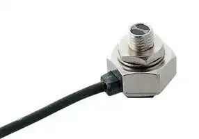


EX-32A-PN
Photoelectric Sensor, EX-30 Series, Ultra Compact, Diffuse, 50mm, PNP, 12 to 24V, Light-ON
- Manufacturer: PANASONIC
- Product type:
- Sensor Output:PNP; Sensing Range Max:50mm; Supply Voltage DC Min:12V; Supply Voltage DC Max:24V; Output Current:50mA; Product Range:EX-30 Series; SVHC:No SVHC (07-Jul-2017)
- SVHC: No SVHC (25-Jun-2025)
- IP Rating: IP67
- Output Type: PNP Open Collector
- Sensor Type: Threaded Miniature Photoelectric Sensors
- Light Source: Red LED
- Product Range: EX-30 Series
- Qualification: -
- Sensing Method: Diffuse Reflective
- Connection Method: Cable
- Sensing Range Max: 50mm
- Sensor Output Type: PNP
- Supply Voltage Max: 24VDC
- Supply Voltage Min: 12VDC
- Sensing Distance Max: 50mm
- Supply Voltage DC Max: 24V
- Supply Voltage DC Min: 12V
- Operating Temperature Max: 55°C
- Operating Temperature Min: -25°C
| Delivery and price | |
|---|---|
| Units per pack | 50 |
| Price | 87.53 € |
| Current stock | 10+ |
| Lead time | 30 days |
341 ~

Threaded Miniature Photoelectric Sensor Amplifier Built-in **EX-30 SERIES Ver.2**

**■** General terms and conditions ............. F-7 **■** Sensor selection guide .................. P.271~ FIBER Related Information SENSORS **■** Glossary of terms........................ P.1455~ **■** General precautions ................... P.1458~ LASER SENSORS PHOTOELECTRIC ~~=~~ SENSORSMICRO ~~|~~ EMC DirectiveConforming to ( 5 m cable length type Excluding Recognition **EX-33** ( **-PN** ),) PHOTOELECTRIC SENSORS AREA SENSORS LIGHT CURTAINS / SAFETY COMPONENTS PRESSURE / FLOW SENSORS INDUCTIVE PROXIMITY SENSORS PARTICULAR USE SENSORS SENSOR OPTIONS SIMPLE WIRE-SAVING Jy UNITS WIRE-SAVING SYSTEMS MEASUREMENT xz SENSORS **panasonic.net/id/pidsx/global** PNP output type available STATIC ELECTRICITY PREVENTION DEVICES LASER MARKERSPLC **The next-generation new form seriesA new alternative to fiber sensors** HUMAN MACHINE INTERFACES **Simpler designpler designler designgnn New design solves all weak points of fiber sensorsgn solves all weak points of fiber sensorsn solves all weak points of fiber sensorspoints of fiber sensorsoints of fiber sensors** ENERGY CONSUMPTION VISUALIZATION COMPONENTS All you need to do is to make a ø4 mm The **EX-30** series solves all of the difficulties associated ø0.157 in hole where you would like  hole where you would like with fiber sensors, such as: FA COMPONENTS to stop or check the object (ø6 mm ø0.236 inFurthermore, the center of the hole for reflective type).Furthermore, the center of the hole for reflective type). hole for reflective type). Center of sensing axisCenter of Center of • Difficulty finding a suitable place for the amplifier• Fragility of the fiber• Extra space needed because of difficulty in bending • Extra space needed because of difficulty in bending MACHINE VISION SYSTEMS ø0.236 inFurthermore, the center of the hole for reflective type).Furthermore, the center of the hole for reflective type). hole for reflective type). sensing axisCenter of Center of • Fragility of the fiber• Extra space needed because of difficulty in bending • Extra space needed because of difficulty in bending sensing axis is the same as the mounting hole the fiber UV CURING SYSTEMS center of the mounting hole, which • The nuisance of having to use a protective tube to

Selection Guide Amplifier Built-in Power Supply Built-in Amplifierseparated

**CX-400 CY-100 EX-10 EX-20 EX-30 EX-40 CX-440 EQ-30 EQ-500 MQ-W RX-LS200 RX RT-610**

**Simpler designpler designler designgnn New design solves all weak points of fiber sensorsgn solves all weak points of fiber sensorsn solves all weak points of fiber sensorspoints of fiber sensorsoints of fiber sensors** All you need to do is to make a ø4 mm The **EX-30** series solves all of the difficulties associated ø0.157 in hole where you would like  hole where you would like with fiber sensors, such as: to stop or check the object (ø6 mm ø0.236 inFurthermore, the center of the hole for reflective type).Furthermore, the center of the hole for reflective type). hole for reflective type). Center of sensing axisCenter of Center of • Difficulty finding a suitable place for the amplifier• Fragility of the fiber• Extra space needed because of difficulty in bending • Extra space needed because of difficulty in bending sensing axis is the same as the mounting hole the fiber center of the mounting hole, which • The nuisance of having to use a protective tube to makes it much easier to set the prevent fiber breakage sensing position.

## **BASIC PERFORMANCE**

## **Electric power saving** *

The **EX-30** series achieves reductions in power consumption of up to 65 %. These sensors contribute to environmental friendliness.

## **Long sensing range**

The **EX-30** series achieves long distance sensing [thru-beam type: 500 mm 19.685 in ( **EX-33** ( **-PN** ): 800 mm 31.496 in), reflective type: 50 mm 1.969 in.]

A maximum **35 %** reduction compared to conventional sensors *Effective from production in April 2011.

## **High response speed of 0.5 ms**

500 mm 19.685 in **EX-33** ( **-PN** ): 50 mm 1.969 in 800 mm 31.496 in Thru-beam type Diffuse reflective type

## **Globally usable**

It conforms to the EMC Directive and obtains the UL Recognition. (excluding 5 m 16.405 ft cable length type) Moreover, PNP output type which is much in demand in Europe, is also available.

The same high response speed of 0.5 ms as fiber sensor amplifiers is provided, making these sensors ideal for sensing small objects, counting objects that are moving quickly and positioning items such as circuit boards.

Threaded Miniature Photoelectric Sensor **EX-30 SERIES Ver.2**

342

LASER SENSORS PHOTOELECTRIC SENSORS MICRO PHOTOELECTRIC SENSORS

Selection Guide Amplifier Built-in Power Supply Built-in Amplifierseparated

~~ee~~ **APPLICATIONS** FIBER SENSORS **Detecting IC height Detecting quantity of labels in Checking IC pins (using slit masks)** LASER SENSORS **label magazine** PHOTOELECTRIC SENSORS MICRO PHOTOELECTRIC SENSORS AREA SENSORS LIGHT CURTAINS / SAFETY COMPONENTSMPONENTSONENTSNENTSS FLOW SS Ge ‘y' SENSORS a INDUCTIVE PROXIMITY SENSORS PARTICULAR USE SENSORS **VARIETIES** SENSOR **New thru-beam types now feature operation mode switch and sensitivity adjuster! EX-33** ( **-PN** ) OPTIONS

AREA SENSORS LIGHT CURTAINS / SAFETY COMPONENTSMPONENTSONENTSNENTSS PRESSURE / FLOW SENSORS INDUCTIVE PROXIMITY SENSORS PARTICULAR USE SENSORS

SENSOR OPTIONS SIMPLE WIRE-SAVING UNITS WIRE-SAVING SYSTEMS MEASUREMENT SENSORS STATIC ELECTRICITY PREVENTION DEVICES

**==> picture [504 x 225] intentionally omitted <==**

**----- Start of picture text -----**<br>
@ 1   Operation mode switch @ 2   Sensitivity adjuster @ 3   Bright 2-color indicator UNITS<br>EX-33 ( -PN )<br>Switching between light-ON and  It is convenient when you need  A bright 2-color indicator has<br>0 dark-ON operating modes is  fine adjustment. been incorporated in all types.<br>00 possible with a single model.<br>Operation mode switch Sensitivity adjuster  Operation indicator Stability indicator<br> (Orange) (Green)<br>800 mm  DEVICES<br>31.496 in<br>PLC<br>Receiver Emitter  Receiver<br>a MOUNTING / SIZE y | RPIPISN<br>Can be installed in the same way as standard fibers Single-point tightening cuts down on installation work by half<br>The  EX-30  series can be screwmounted (M4 for thru- Conventional photoelectric sensors required four (for<br>beam type, M6 for reflective type) in the same way as  thru-beam type) or two (for reflective type) mounting<br>standard fiber sensors. This means that they can be  holes and screws to be used. However, the  EX-30  series<br>inserted into production lines in exactly the same way as  is installed with a single screw, thus cutting down on<br>conventional high-priced fiber sensors. installation work by half.<br>**----- End of picture text -----**<br>


LASER MARKERS PLC

HUMAN MACHINE INTERFACES ENERGY CONSUMPTION VISUALIZATION COMPONENTS

FA COMPONENTS MACHINE VISION SYSTEMS UV CURING SYSTEMS

**==> picture [86 x 60] intentionally omitted <==**

**----- Start of picture text -----**<br>
M4<br>Thru-beam type<br> (Reflective type: M6)<br>**----- End of picture text -----**<br>


## **Takes up very little space**

Unlike conventional fibers, bending radius is not a problem, so that the sensor can be securely installed alongside conveyors.

**==> picture [171 x 13] intentionally omitted <==**

**----- Start of picture text -----**<br>
7 | EX-30 [| Fiber<br>**----- End of picture text -----**<br>


**==> picture [179 x 18] intentionally omitted <==**

**----- Start of picture text -----**<br>
Conventional model EX-30<br>[ [|<br>**----- End of picture text -----**<br>


**CX-400 CY-100 EX-10 EX-20 EX-30 EX-40 CX-440 EQ-30 EQ-500 MQ-W RX-LS200 RX RT-610**

Threaded Miniature Photoelectric Sensor **EX-30 SERIES Ver.2**

343

~~OO~~ FIBER rrr **ENVIRONMENTAL RESISTANCE** eee **FUNCTIONS** SENSORS LASER **Incorporated an inverter countermeasure circuit* Bright 2-color indicator** SENSORS PHOTOELECTRICSENSORS Thesignificantly stronger against inverter **EX-30** series become Fluoressent light A bright 2-color indicator is incorporated in all Stability indicator (Green) MICRO light and other extraneous light. types. PHOTOELECTRICSENSORS *Effective from production in April 2011. Operation indicator (Orange) AREA SENSORS LIGHT CURTAINS / SAFETY COMPONENTS PRESSURE / FLOW SENSORS INDUCTIVE PROXIMITYSENSORS **No protective tube needed OPERABILITY** USE SENSORSPARTICULAR The **EX-30** series has high **Incorporates a sensitivity adjuster (Excluding EX-31□)**

The **EX-30** series has high bending strength, so that the protective tube used to No protective tube protect conventional fiber needed from breakage is not needed. This also adds up to excellent cost performance.

The sensor incorporates Sensitivityadjusteradjusterjusteruster a sensitivity adjuster. It is convenient when you need fine adjustment.

**==> picture [541 x 537] intentionally omitted <==**

**----- Start of picture text -----**<br>
|||||||||||
|---|---|---|---|---|---|---|---|---|---|
|OPTIONSSENSOR|the protective tube used to|No protective tube|The sensor incorporates|Sensitivityadjusteradjusterjusteruster|
|protect conventional fiber|a sensitivity adjuster. It is|
|SIMPLE|needed|
|WIRE-SAVING|from breakage is not needed.|convenient when you need|
|UNITS|This also adds up to excellent|fine adjustment.|
|WIRE-SAVING|cost performance.|
|SYSTEMS|
|MEASUREMENT|Waterproof IP67 (IEC)|
|SENSORS|
|The sensor can be hosed|
|STATIC ELECTRICITY|
|PREVENTION|down because of its IP67|
|DEVICES|construction.|
|LASER|
|MARKERS|
|Note: However, take care that if it|
|is exposed to water splashes|zy|SQ|
|PLC|
|during operation, it may detect|
|ee|HUMAN MACHINE|a water drop itself.|bos|
|INTERFACES|
|ENERGY CONSUMPTION|
|a|VISUALIZATION COMPONENTS|ORDER GUIDE|
|FA COMPONENTS|
|MACHINE VISION SYSTEMS|Type|Appearance|Sensing range|Model No.(Note)|Output|Outputoperation|
|—|a|ee|ee|
|UV CURING SYSTEMS|EX-31A|NPN open-collector|Light-ON|
|500 mm|EX-31B|transistor|Dark-ON|
|19.685 in|EX-31A-PN|Light-ON|
|PNP open-collector|
|EX-31B-PN|transistor|Dark-ON|
|a|Pj|
|NPN open-collector|
|Selection Amplifier Guide|800 mm31.496 in|EX-33|transistorPNP open-collector|Switchableeither Light-ON or Dark-ON|
|Built-in|EX-33-PN|transistor|
|Power Supply|
|(el|Built-in|—_—|
|EX-32A|Light-ON|
|Amplifier-|NPN open-collector|
|separated|50 mm|EX-32B|transistor|Dark-ON|
|1.969 in|EX-32A-PN|Light-ON|
|CX-400|PNP  open-collector|
|EX-32B-PN|transistor|Dark-ON|
|—|CY-100EX-10|Note: The model No. with “|(P=)|P|” shown on the label affixed to the thru-beam type sensor is the emitter, “|||D|” shown on the label is the receiver.|—|
|EX-20|5 m 16.404 ft cable length type|
|—|EX-30|5 m 16.404 ft cable length type(standard: 2 m 6.562 ft) is also available for NPN output type [excluding|EX-33|(|-PN|)].|
|EX-40|When ordering this type, suffix “(e.g.) 5 m 16.404 ft cable length type of|-C5|” to the model No.|EX-31A|is “|EX-31A-C5|”.|
|CX-440|
|EQ-30|
|EQ-500|
|MQ-W|
|RX-LS200|
|RX|
|RT-610|

**----- End of picture text -----**<br>


Threaded Miniature Photoelectric Sensor **EX-30 SERIES Ver.2**

344

FIBER SENSORS LASER SENSORS PHOTOELECTRIC SENSORS MICRO PHOTOELECTRIC SENSORS AREA SENSORS LIGHT CURTAINS / SAFETY COMPONENTS PRESSURE / FLOW SENSORS INDUCTIVE PROXIMITY SENSORS PARTICULAR USE SENSORS SENSOR OPTIONS SIMPLE WIRE-SAVING UNITS WIRE-SAVING SYSTEMS

MEASUREMENT SENSORS STATIC ELECTRICITY PREVENTION DEVICES LASER MARKERS PLC

HUMAN MACHINE INTERFACES ENERGY CONSUMPTION VISUALIZATION COMPONENTS FA COMPONENTS MACHINE VISION SYSTEMS UV CURING SYSTEMS

Selection Guide Amplifier Built-in Power Supply Built-in Amplifierseparated

## **OPTIONS**

**==> picture [331 x 98] intentionally omitted <==**

**----- Start of picture text -----**<br>
Designation Model No. Description<br>• Sensing range: 200 mm 7.874 in [ EX-31□ ( -PN )]<br>Slit on one side 320 mm 12.598 in [ EX-33 ( -PN )]<br>Slit mask OS-EX30-1 • Min. sensing object: ø2 mm ø0.079 in<br>For thru-beam  Slit size ø1 mm<br>type sensor only ø0.039 in • Sensing range: 150 mm 5.906 in [ EX-31□ ( -PN )]<br>Slit on both sides 240 mm 9.449 in [ EX-33 ( -PN )]<br>• Min. sensing object: ø1 mm ø0.039 in<br>**----- End of picture text -----**<br>


Note: One slit and two spacers are provided per set. Two sets are required when installing on both sides.

## **Slit mask**

**==> picture [50 x 48] intentionally omitted <==**

**• OS-EX30-1**

Apply the optional slit mask when detecting small objects or for increasing the accuracy of sensing position.

However, the sensing range is reduced when the slit mask is mounted.

## **SPECIFICATIONS**

**==> picture [504 x 532] intentionally omitted <==**

**----- Start of picture text -----**<br>
Type Thru-beam Diffuse reflective<br>With operation mode switch<br>NPN output EX-31A EX-31B EX-33 EX-32A EX-32B<br>Item PNP output EX-31A-PN EX-31B-PN EX-33-PN EX-32A-PN EX-32B-PN<br>Sensing range 500 mm 19.685 in 800 mm 31.496 in 50 mm 1.969 in (Note 2)<br>Sensing object ø2 mm ø0.079 in or more opaque object (Completely beam interrupted objects) Opaque, translucent or transparent object (Note 3)<br>Hysteresis – 15 % or less of operation distance (Note 2)<br>Repeatability 0.05 mm 0.002 in or less 0.5 mm 0.020 in or less<br>(perpendicular to sensing axis)<br>Supply voltage 12 to 24 V DC ±10 %  Ripple P-P 10 % or less<br>Current consumption Emitter: 10 mA or less, Receiver: 10 mA or less 13 mA or less<br><NPN output type> <PNP output type><br>NPN open-collector transistor PNP open-collector transistor<br>• Maximum sink current: 50 mA • Maximum source current: 50 mA<br>Output<br>• Applied voltage: 30 V DC or less (between output and 0 V) • Applied voltage: 30 V DC or less (between output and +V)<br>• Residual voltage: 2 V or less (at 50 mA sink current) • Residual voltage: 2 V or less (at 50 mA source current)<br>1 V or less (at 16 mA sink current) 1 V or less (at 16 mA source current)<br>Utilization category DC-12 or DC-13<br>Switchable either<br>Output operation Light-ON Dark-ON Light-ON Dark-ON<br>Light-ON or Dark-ON<br>Short-circuit protection Incorporated<br>Response time 0.5 ms or less<br>Operation indicator Orange LED (lights up when the output is ON) (incorporated on the receiver for thru-beam type)<br>Green LED Green LED<br>Stability indicator lights up under stable light received condition or  lights up under stable light received condition or<br>stable dark condition, incorporated on the receiver stable dark condition<br>Sensitivity adjuster – Continuously variable adjuster<br>Pollution degree 3 (Industrial environment)<br>Protection IP67 (IEC)<br>Ambient temperature –25 to +55 °C –13 to +131 °F (No dew condensation or icing allowed), Storage: –30 to +70 °C –22 to +158 °F<br>Ambient humidity 35 to 85 % RH, Storage: 35 to 85 % RH<br>Ambient illuminance Incandescent light: 3,000 ℓx at the light-receiving face<br>EMC EN 60947-5-2<br>Voltage withstandability 1,000 V AC for one min. between all supply terminals connected together and enclosure<br>Insulation resistance 20 MΩ, or more, with 250 V DC megger between all supply terminals connected together and enclosure<br>Vibration resistance 10 to 500 Hz frequency, 3 mm 0.118 in amplitude (20 G max.) in X, Y and Z directions for two hours each<br>Shock resistance 500 m/s [2]  acceleration (50 G approx.) in X, Y and Z directions for three times each<br>Emitting element Red LED (modulated)<br>Material Enclosure: Die-cast zinc (Nickel plated), Lens: Polycarbonate [ EX-32 □( -PN ): Acrylic], Enclosure cover: Polycarbonate<br>Cable 0.1 mm [2]  3-core (thru-beam type sensor emitter: 2-core) cabtyre cable, 2 m 6.562 ft long<br>Cable extension Extension up to total 50 m 164.042 ft is possible with 0.3 mm [2] , or more, cable (thru-beam type: both emitter and receiver).<br>Net weight (each emitter and receiver): 20 g approx.<br>Weight Gross weight: 65 g approx. Net weight: 20 g approx., Gross weight: 45 g approx.<br>Accessories Nut: 2 pcs., Toothed lock washer: 2 pcs. Nut: 1 pc., Toothed lock washer: 1 pc.<br>Model No.<br>Environmental resistance<br>**----- End of picture text -----**<br>


Notes: 1) Where measurement conditions have not been specified precisely, the conditions used were an ambient temperature of +23 °C +73.4 °F. 2) The sensing range and the hysteresis are specified for white non-glossy paper (100 × 100 mm 3.937 × 3.937 in) as the object.

- 3) Make sure to confirm detection with an actual sensor before use.

**CX-400 CY-100 EX-10 EX-20 EX-30 EX-40 CX-440 EQ-30 EQ-500 MQ-W RX-LS200 RX RT-610**

Threaded Miniature Photoelectric Sensor **EX-30 SERIES Ver.2**

345

FIBER SENSORS LASER SENSORS PHOTOELECTRIC SENSORS MICRO PHOTOELECTRIC SENSORS AREA SENSORS LIGHT CURTAINS / SAFETY COMPONENTS PRESSURE / FLOW SENSORS

INDUCTIVE PROXIMITY SENSORS PARTICULAR USE SENSORS

SENSOR OPTIONS SIMPLE WIRE-SAVING UNITS WIRE-SAVING SYSTEMS MEASUREMENT SENSORS STATIC ELECTRICITY PREVENTION DEVICES LASER MARKERS PLC

HUMAN MACHINE INTERFACES ENERGY CONSUMPTION VISUALIZATION COMPONENTS FA COMPONENTS

MACHINE VISION SYSTEMS UV CURING SYSTEMSCURING

## **I/O CIRCUIT AND WIRING DIAGRAMS**

## **NPN output type**

**I/O circuit diagram**

**==> picture [233 x 88] intentionally omitted <==**

**----- Start of picture text -----**<br>
Color code<br>D1 (Brown) +V<br>Load<br>D2 (Black) Output (Note)   +  12 to 24 V DC<br>Tr  Z D 50 mA  max.  –   ± 10 %<br>(Blue) 0 V<br>Internal circuit  Users’ circuit<br>Sensor circuit<br>**----- End of picture text -----**<br>


## **Wiring diagram**

**==> picture [120 x 66] intentionally omitted <==**

**----- Start of picture text -----**<br>
Color code<br>Brown<br>Load<br>Black (Note)   +  12 to 24 V DC<br> –   ± 10 %<br>Blue<br>**----- End of picture text -----**<br>


Note: The emitter of the thru-beam type sensor does not incorporate the black wire.

Note: The emitter of the thru-beam type sensor does not incorporate the output.

Symbols … D1 : Reverse supply polarity protection diode D2 : Reverse output polarity protection diode ZD : Surge absorption zener diode Tr : NPN output transistor

## **PNP output type**

**I/O circuit diagram**

**==> picture [232 x 88] intentionally omitted <==**

**----- Start of picture text -----**<br>
Color code<br>(Brown) +V<br>Tr<br>Z D 50 mA  max.   +  12 to 24 V DC<br>D2 (Black) Output (Note)   –   ± 10 %<br>Load<br>D1 (Blue) 0 V<br>Internal circuit  Users’ circuit<br>Sensor circuit<br>**----- End of picture text -----**<br>


## **Wiring diagram**

**==> picture [121 x 66] intentionally omitted <==**

**----- Start of picture text -----**<br>
Color code<br>Brown<br>Black (Note)   +  12 to 24 V DC<br>Load   –   ± 10 %<br>Blue<br>**----- End of picture text -----**<br>


Note: The emitter of the thru-beam type sensor does not incorporate the black wire.

Note: The emitter of the thru-beam type sensor does not incorporate the output.

Symbols … D1 : Reverse supply polarity protection diode D2 : Reverse output polarity protection diode ZD : Surge absorption zener diode Tr : PNP output transistor

## **SENSING CHARACTERISTICS (TYPICAL)**

**==> picture [553 x 325] intentionally omitted <==**

**----- Start of picture text -----**<br>
SYSTEMS EX-31□  EX-31□-PN Thru-beam type<br>UV<br>SYSTEMSCURING  Parallel deviation Angular deviation Parallel deviation with slit mask on one side Parallel deviation with slit masks on both sides<br>800 800<br>31.496 31.496<br>200  200<br>600  600  7.874 7.874<br>23.622 23.622<br>Selection Guide 15.748400  Emitter  15.748400  Emitter  Emitter  Emitter<br>Power Supply Amplifier Built-inBuilt-in 7.874200  ℓ  L  7.874200  θ  L  3.937100  ℓ  L  3.937100  ℓ  L<br>seAmplifier-parated 0   Receiver  0   Receiver  0   Receiver  0   Receiver<br>100 50 0  50 100 40  20  0  20  40  40 20 0  20 40 40 20 0  20 40<br>3.937 1.969 1.969 3.937 Left  Center  Right  1.575 0.787 0.787 1.575 1.575 0.787 0.787 1.575<br>CX-400 Left Operating point ℓ (mm Center  Right in) Operating angle θ ( ° )  Left Operating point ℓ (mm Center  Right in) Left Operating point ℓ (mm Center  Right in)<br>CY-100<br>EX-10 EX-31□  EX-31□-PN Thru-beam type EX-32□  EX-32□-PN Diffuse reflective type<br>EX-20 Correlation between setting distance and excess gain Sensing field Correlation between sensing object size and sensing range Correlation between setting distance and excess gain<br>100  80  80  100<br>EX-30 3.150 3.150 As the sensing object size becomes smaller than<br>50  the standard size (white non-glossy paper 50<br>CX-440EX-40 2.36260  2.36260  100 × 100 mm shortens, as shown in this graph.3.937 × 3.937 in), the sensing range<br>100 × 100 mm<br>EQ-30 10  40  3.937 × 3.937 in 40  a × a mm a × a in 10<br>1.575 White non-glossy paper 1.575 White non-glossy paper<br>EQ-500<br>MQ-W 5  20  ℓ  L  20  L  5<br>0.787 0.787<br>RX-LS200 Sensor<br>Sensor<br>RX 1  0   1<br>0  400 800 1,200 1,600 2,000 10 5 0  5 10 0  50 100 150 200 0  50 100 150 200 250<br>RT-610 15.748Setting distance L (mm 31.496 47.244 62.992in) 78.740 0.394 Left 0.197 Center  0.197Right  0.394 1.969White non-glossy paper 3.937 5.906 7.874 1.969Setting distance L (mm 3.937 5.906 7.874in) 9.843<br>Operating point ℓ (mm in) side length a (mm in)<br>)in )in )in )in<br>Setting distance L (mm  Setting distance L (mm  Setting distance L (mm  Setting distance L (mm<br>)in )in<br>Excess gain  Excess gain<br>Setting distance L (mm  Sensing range L (mm<br>**----- End of picture text -----**<br>


Threaded Miniature Photoelectric Sensor **EX-30 SERIES Ver.2**

346

FIBER SENSORS LASER SENSORS PHOTOELECTRIC SENSORS MICRO PHOTOELECTRIC SENSORS AREA SENSORS LIGHT CURTAINS / SAFETY COMPONENTS PRESSURE / FLOW SENSORS INDUCTIVE PROXIMITY SENSORS PARTICULAR USE SENSORS

SENSOR OPTIONS

SIMPLE WIRE-SAVING UNITS WIRE-SAVING SYSTEMS

MEASUREMENT SENSORS STATIC ELECTRICITY PREVENTION DEVICES LASER MARKERS

PLC

HUMAN MACHINE INTERFACES ENERGY CONSUMPTION VISUALIZATION COMPONENTS FA COMPONENTS MACHINE VISION SYSTEMS UV CURING SYSTEMS

Selection Guide Amplifier Built-in Power Supply Built-in Amplifierseparated

## **SENSING CHARACTERISTICS (TYPICAL)**

**==> picture [507 x 158] intentionally omitted <==**

**----- Start of picture text -----**<br>
EX-33  EX-33-PN Thru-beam type<br>Parallel deviation Angular deviation Parallel deviation with slit mask on one side Parallel deviation with slit masks on both sides<br>400 400<br>15.748 15.748<br>1,000 1,000<br>39.370 39.370  300 300<br>11.811 11.811<br>Emitter<br>500 ℓ L 500  Emitter  2007.874  Emitter 2007.874  Emitter<br>19.685 Receiver 19.685  θ  L  100 ℓ L 100 ℓ L<br>3.937  3.937<br>Receiver  Receiver Receiver<br>0 0  0 0<br>100 50 0 50 100 40 20 0  20 40 40 20 0 20 40 40 20 0 20 40<br>3.937 1.969 1.969 3.937 1.575 0.787 0.787 1.575 1.575 0.787 0.787 1.575 1.575 0.787 0.787 1.575<br>Left Center Right Left Center Right Left Center Right Left Center Right<br>Operating point ℓ (mm in) Operating angle θ ( ° ) Operating point ℓ (mm in) Operating point ℓ (mm in)<br>)in )in )in )in<br>Setting distance L (mm  Setting distance L (mm  Setting distance L (mm  Setting distance L (mm<br>**----- End of picture text -----**<br>


## **PRECAUTIONS FOR PROPER USE**

Refer to p.1458~ for general precautions.

   - Do not use during the initial transient time (50 ms) after the power supply is switched on.

- Never use this product as a sensing device for personnel protection.

- In case of using sensing devices for personnel protection, use products which meet laws and standards, such as OSHA, ANSI or IEC etc., for personnel protection applicable in each region or country.

- In case of using the sensor at a place where static electricity is generated, use a metal mounting plate. Also, ensure to ground the mounting plate.

## **DIMENSIONS (Unit: mm in)**

The CAD data in the dimensions can be downloaded from our website

**==> picture [502 x 441] intentionally omitted <==**

**----- Start of picture text -----**<br>
EX-31□  EX-31□-PN Sensor EX-33  EX-33-PN Sensor<br>Opposing faces 7 thickness 2.4 0.094 0.276,  Stability indicator (Green) (Note)  Opposing faces 7 thickness 2.4 0.094 0.276,  Stability indicator (Green) (Note 1)<br>Toothed lock washer<br>Toothed lock washer  ø8.5 ø0.035<br>ø8.5 ø0.035  Operation indicator  Operation indicator<br>15.6  0.012 0.3  (Orange) (Note)  0.614 15.6  0.012 0.3  (Orange) (Note 1)<br>0.614  11<br>0.433<br>0.122 3.1 Beam axis  3.1 0.122  Beam axis  0.323 8.2<br>0.551 14  0.276 7  0.276 7  0.551 14  0.276 7  0.276 7  Operation mode switch (Note 2)<br>14  14  ø7.2<br>0.551  0.551  ø0.283<br>M4 × 0.7  M4 × 0.7  0.75<br>0.028  0.028  0.030<br>3  3<br>0.118  5.1  0.118 5.1<br>0.201  ø2.5 ø0.098 cable, 2 m 6.562 ft long  0.201  ø2.5 ø0.098 cable, 2 m 6.562 ft long<br>3.8<br>0.150  3.8<br>0.150<br>Note: Not incorporated on the emitter. Notes: 1) Not incorporated on the emitter.<br>2) It is the sensitivity adjuster on the emitter.<br>EX-32□  EX-32□-PN Sensor OS-EX30-1 Slit mask (optional)<br>Opposing faces 10 0.394,  Toothed lock washer ø11 ø0.433<br>thickness 2 0.079  Stability indicator  Slit mask<br>(Green)<br>(5.3)<br>(0.209)<br>7<br>0.3  Operation indicator  (0.276)<br>0.012  (Orange)<br>15.6  (8.02)<br>0.614  11  (0.316)<br>0.201 5.1  Beam- receiving part   7  8.2 7  Internal thread part M4 × 0.7 3.8 0.150 deep 0.028,  ø1 ø0.039<br>14  0.276  0.276  Sensitivity<br>0.551  adjuster  Material: Brass(Nickel plated)<br>14  ø7.2  Spacer<br>0.551  ø0.283<br>M4 × 0.75  0.75<br>3 0.118  0.030  0.030<br>ø8  ø4.3<br>Beam-  ø0.315  ø0.169<br>emitting  1<br>part   0.201 5.1  ø2.5 ø0.098 cable, 2 m 6.562 ft long  Material: POM 0.039<br>3.8<br>0.150<br>**----- End of picture text -----**<br>


**CX-400 CY-100 EX-10 EX-20 EX-30 EX-40 CX-440 EQ-30 EQ-500 MQ-W RX-LS200 RX**

**RT-610**
Updated at April 28, 2026
Panasonic Industry is a global leader in the design and manufacture of high-quality electronic components. Renowned for a commitment to continuous innovation, the company provides the essential building blocks that empower modern engineering. From industrial automation to consumer electronics, Panasonic's components are trusted worldwide for their outstanding reliability, efficiency, and long-term performance. The extensive portfolio is anchored by a massive selection of passive components, featuring an industry-leading range of aluminium electrolytic, film, and polymer capacitors. Alongside these advanced capacitance solutions, engineers rely on Panasonic's robust power inductors and a highly versatile array of electromechanical devices, including solid-state, power, and signal relays engineered to excel in demanding environments. Beyond core passives and switching solutions, the offering encompasses critical circuit protection devices such as TVS varistors and NTC thermistors, as well as sophisticated thermal management materials. Panasonic also delivers precision light and motion sensors, highly reliable batteries, and advanced Bluetooth and WLAN connectivity modules, providing a comprehensive ecosystem of components to support next-generation technological design.
About Novapart
Novapart is a B2B electronic component broker specialising in stock shortages and cost reduction. We source hard-to-find parts and identify compliant alternatives across a catalogue of 410,000+ components from 500+ manufacturers.
Learn more →Stock Shortage Specialist
When a component is unavailable, discontinued or has an unacceptable lead time, we tap into our network of vetted European and Asian distributors to source what you need — without compromising on quality or traceability.
Request a quote →Compliant Alternatives
We identify pin-to-pin, electrically equivalent substitutes that meet the same certifications (RoHS, AEC-Q100, REACH) as your original specification — validated against datasheets, not just part numbers. Often at a lower cost.
BOM Analysis service →