
Image not available
Illustrative purposes only

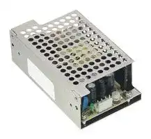
EPS-45-5-C
AC/DC Enclosed Power Supply (PSU), 127 to 370VDC, ITE, 1 Outputs, 40 W, 5 VDC, 8 A
⚠️ Reference pricing provided. In case of supply shortages, we will connect you with our trusted procurement partners to ensure your project's continuity.
- Manufacturer: MEAN WELL
- Product type: AC / DC Enclosed Power Supplies
- SVHC: No SVHC (25-Jun-2025)
- Product Range: EPS-45 Series
- No. of Outputs: 1Outputs
- Output Power Max: 40W
- Input Voltage VAC: 90V AC to 264V AC
- Power Supply Output Type: Adjustable, Fixed
- Output Current - Output 1: 8A
- Output Current - Output 2: -
- Output Current - Output 3: -
- Output Current - Output 4: -
- Output Voltage - Output 1: 5VDC
- Output Voltage - Output 2: -
- Output Voltage - Output 3: -
- Output Voltage - Output 4: -
- Power Supply Applications: ITE
| Delivery and price | |
|---|---|
| Units per pack | 250 |
| Price | 10.62 € |
| Current stock | 10+ |
| Lead time | 30 days |
Datasheet

**EPS - 45 series**

45W Single Output Switching Power Supply

## ■

×

**==> picture [13 x 17] intentionally omitted <==**

**----- Start of picture text -----**<br>
BauarSicherheitbeegelodwacmat geprufto ges g<br>www.ID 2000000000tuv.com<br>**----- End of picture text -----**<br>


## **SPECIFICATION**

|**MODEL**<br>**EPS-45-3.3**<br>**EPS-45-12**<br>**EPS-45-5**<br>**EPS-45-7.5**<br>**EPS-45-15**<br>**EPS-45-24**<br>**EPS-45-48**<br>**DC VOLTAGE**<br>**RATED CURRENT**<br>**CURRENT RANGE**<br>**RATED POWER**<br>**OUTPUT**<br>**VOLTAGE ADJ. RANGE**<br>**LINE REGULATION**<br>**LOAD REGULATION**<br>**SETUP, RISE TIME**<br>**HOLD UP TIME (Typ.)**<br>**VOLTAGE RANGE**<br>**Note.5**<br>**FREQUENCY RANGE**<br>**EFFICIENCY (Typ.)**<br>**AC CURRENT (Typ.)**<br>**INPUT**<br>**INRUSH CURRENT (Typ.)**<br>**LEAKAGE CURRENT**<br>**SAFETY STANDARDS**<br>**EMC IMMUNITY**<br>**WORKING TEMP.**<br>**WORKING HUMIDITY**<br>**STORAGE TEMP., HUMIDITY**<br>**TEMP. COEFFICIENT**<br>**VIBRATION**<br>**MTBF**<br>**DIMENSION**<br>**OTHERS**<br>**NOTE**<br>**PACKING**<br>**OVER LOAD**<br>**OVER VOLTAGE**<br>3.3V<br>12V<br>5V<br>7.5V<br>15V<br>24V<br>48V<br>8A<br>3.75A<br>8A<br>5.4A<br>3A<br>1.9A<br>1A<br>0 ~ 9A<br>0 ~ 4.2A<br>0 ~ 9A<br>0 ~ 6A<br>0 ~ 3.3A<br>0 ~ 2.1A<br>0 ~ 1.1A<br>26.4W<br>45W<br>40W<br>40.5W<br>45W<br>45.6W<br>48W<br>80mVp-p<br>120mVp-p<br>80mVp-p<br>100mVp-p<br>150mVp-p<br>240mVp-p<br>300mVp-p<br>3.1 ~ 3.6V<br>10.8 ~ 13.5V<br>4.75 ~ 5.5V<br>7.13 ~ 8.25V<br>13.5 ~ 16.5V<br>21.6 ~ 27V<br>43.2 ~ 52.8V<br>±3.0%<br>±0.5%<br>±2.0%<br>1000ms, 50ms/230VAC         2000ms, 50ms/115VAC at full load<br>50ms/230VAC          16ms/115VAC at full load<br>47 ~ 63Hz<br>3.7 ~ 4.45V<br>5.6 ~ 6.75V<br>8.63 ~ 10.1V<br>13.8 ~ 16.2V<br>17.25 ~ 20.25V 27.6 ~ 32.4V<br>53.3 ~ 64.8V<br>80%<br>87%<br>82%<br>84%<br>88%<br>89%<br>90%<br>1.8A/115VAC           1 A/230VAC<br>COLD START 60A/230VAC<br>115 ~ 160% rated output power<br>-30 ~ +70<br>(Refer to output load derating curve)<br>℃<br>20 ~ 90% RH non-condensing<br>-40 ~ +85<br>, 10 ~ 95% RH<br>℃<br>±<br>℃<br>℃<br>0.03%/<br>(0 ~ 50<br>)<br>10 ~ 500Hz, 2G 10min./1cycle, period for 60min. each along X, Y, Z axes<br>652.3Khrs min.      MIL-HDBK-217F (25<br>)<br>℃<br>PCB:101.6*50.8*29mm (L*W*H) ; with optional CASE:103.4*62*37mm (L*W*H)<br>**WITHSTAND VOLTAGE**<br>**ISOLATION RESISTANCE**<br>I/P-O/P, I/P-FG, O/P-FG:100M Ohms / 500VDC / 25<br>/ 70% RH<br>℃<br>**ENVIRONMENT**<br>**SAFETY &**<br>**EMC**<br>**(Note 4)**<br>**PROTECTION**<br>**EMC EMISSION**<br>1. All parameters NOT specially mentioned are measured at 230VAC input, rated load and 25<br>of ambient temperature.<br>℃<br>2. Ripple & noise are measured at 20MHz of bandwidth by using a 12" twisted pair-wire terminated with a 0.1uf & 47uf parallel capacitor.<br>3. Tolerance : includes set up tolerance, line regulation and load regulation.<br>4. Derating may be needed under low input voltage. Please check the static characteristics for more details.<br>5. 33% Duty cycle maximum within every 30 seconds. Average output power should not exceed the rated power.<br>6. The power supply is considered a component which will be installed into a final equipment. All the EMC tests are been executed by<br>on a<br>mm*<br>mm metal plate with 1mm of thickness. The final equipment must be re-confirmed that it still meets<br>360<br>360<br>For guidance on how to perform these EMC tests, please refer to “EMI testing of component power supplies.”<br>(as available on http://www.meanwell.com)<br>7. The ambient temperature derating of 3.5<br>/1000m with fanless models and of 5<br>/1000m with fan models for operating altitude higher than 2000m(6500ft).<br>℃<br>℃<br>https://www.meanwell.com/serviceDisclaimer.aspx<br>※Product Liability Disclaimer<br>For detailed information, please refer to<br>:<br>**RIPPLE & NOISE (max.) Note.2**<br>**VOLTAGE TOLERANCE Note.3**<br>Protection type : Hiccup mode, recovers automatically after fault condition is removed<br>Protection type :  Shut down o/p voltage, re-power on to recover<br>UL62368-1, TUV EN62368-1<br>approved<br>, EAC TP TC 004<br><2mA/240VAC<br>I/P-O/P:3KVAC     I/P-FG:2KVAC     O/P-FG:0.5KVAC<br>PCB:  0.14Kg; 96pcs/ 14.5Kg/1.39CUFT ; with optional CASE: 0.3Kg; 45pcs/ 14.5Kg/0.63CUFT<br>±2.0%<br>±2.0%<br>±0.5%<br>±0.5%<br>±1.0%<br>±1.0%<br>±2.0%<br>±0.5%<br>±1.0%<br>±2.0%<br>±0.5%<br>±1.0%<br>±1.0%<br>±0.5%<br>±1.0%<br>±1.0%<br>±0.5%<br>±1.0%<br>**EPS-45-36**<br>36V<br>1.25A<br>0 ~ 1.4A<br>45W<br>280mVp-p<br>32.4 ~ 39.6V<br>±1.0%<br>±0.5%<br>±1.0%<br>89%<br>39.7 ~ 46.8V<br>29.7W<br>50.4W<br>45W<br>42W<br>49.5W<br>50.4W<br>52.8W<br>50.4W<br>**PEAK LOAD(10sec.)**<br>**Note.6**<br>Compliance to EN55032 (CISPR32) Class B, EN61000-3-2,-3, EAC TP TC 020<br>Compliance to EN61000-4-2,3,4,5,6,8,11, EN55024, heavy industry level, criteria A, EAC TP TC 020<br>90 ~ 264VAC         127 ~ 370VDC<br>[DC input operation possible by connecting AC/N(+), AC/L(-)]<br>**OPERATING ALTITUDE Note.7** 4000 meters<br>**R**e~~GGG~~<br>~~**G**~~<br>G<br>~~eG~~<br>~~GC~~<br>~~Re~~<br>eG ~~**G**C~~<br>~~**R**eGG~~<br>GQ<br>~~GQ~~<br>Re<br>GG<br>QO<br>CO<br>Re~~GGG~~<br>~~GG~~<br>~~GG~~<br>~~Rn~~<br>~~a~~<br>~~|~~<br>~~a~~<br>~~———{$[{_="~~<br>~~ee~~<br>~~|~~<br>~~eeCe~~<br>~~|~~<br>i<br>rrr<br>PO<br>a<br>a<br>a~~CP~~<br>a<br>a<br>aRe<br>~~Cn~~<br>a<br>a<br>a<br>I<br>a<br>fer<br>EMC directives.|**MODEL**<br>**EPS-45-3.3**<br>**EPS-45-12**<br>**EPS-45-5**<br>**EPS-45-7.5**<br>**EPS-45-15**<br>**EPS-45-24**<br>**EPS-45-48**<br>**DC VOLTAGE**<br>**RATED CURRENT**<br>**CURRENT RANGE**<br>**RATED POWER**<br>**OUTPUT**<br>**VOLTAGE ADJ. RANGE**<br>**LINE REGULATION**<br>**LOAD REGULATION**<br>**SETUP, RISE TIME**<br>**HOLD UP TIME (Typ.)**<br>**VOLTAGE RANGE**<br>**Note.5**<br>**FREQUENCY RANGE**<br>**EFFICIENCY (Typ.)**<br>**AC CURRENT (Typ.)**<br>**INPUT**<br>**INRUSH CURRENT (Typ.)**<br>**LEAKAGE CURRENT**<br>**SAFETY STANDARDS**<br>**EMC IMMUNITY**<br>**WORKING TEMP.**<br>**WORKING HUMIDITY**<br>**STORAGE TEMP., HUMIDITY**<br>**TEMP. COEFFICIENT**<br>**VIBRATION**<br>**MTBF**<br>**DIMENSION**<br>**OTHERS**<br>**NOTE**<br>**PACKING**<br>**OVER LOAD**<br>**OVER VOLTAGE**<br>3.3V<br>12V<br>5V<br>7.5V<br>15V<br>24V<br>48V<br>8A<br>3.75A<br>8A<br>5.4A<br>3A<br>1.9A<br>1A<br>0 ~ 9A<br>0 ~ 4.2A<br>0 ~ 9A<br>0 ~ 6A<br>0 ~ 3.3A<br>0 ~ 2.1A<br>0 ~ 1.1A<br>26.4W<br>45W<br>40W<br>40.5W<br>45W<br>45.6W<br>48W<br>80mVp-p<br>120mVp-p<br>80mVp-p<br>100mVp-p<br>150mVp-p<br>240mVp-p<br>300mVp-p<br>3.1 ~ 3.6V<br>10.8 ~ 13.5V<br>4.75 ~ 5.5V<br>7.13 ~ 8.25V<br>13.5 ~ 16.5V<br>21.6 ~ 27V<br>43.2 ~ 52.8V<br>±3.0%<br>±0.5%<br>±2.0%<br>1000ms, 50ms/230VAC         2000ms, 50ms/115VAC at full load<br>50ms/230VAC          16ms/115VAC at full load<br>47 ~ 63Hz<br>3.7 ~ 4.45V<br>5.6 ~ 6.75V<br>8.63 ~ 10.1V<br>13.8 ~ 16.2V<br>17.25 ~ 20.25V 27.6 ~ 32.4V<br>53.3 ~ 64.8V<br>80%<br>87%<br>82%<br>84%<br>88%<br>89%<br>90%<br>1.8A/115VAC           1 A/230VAC<br>COLD START 60A/230VAC<br>115 ~ 160% rated output power<br>-30 ~ +70<br>(Refer to output load derating curve)<br>℃<br>20 ~ 90% RH non-condensing<br>-40 ~ +85<br>, 10 ~ 95% RH<br>℃<br>±<br>℃<br>℃<br>0.03%/<br>(0 ~ 50<br>)<br>10 ~ 500Hz, 2G 10min./1cycle, period for 60min. each along X, Y, Z axes<br>652.3Khrs min.      MIL-HDBK-217F (25<br>)<br>℃<br>PCB:101.6*50.8*29mm (L*W*H) ; with optional CASE:103.4*62*37mm (L*W*H)<br>**WITHSTAND VOLTAGE**<br>**ISOLATION RESISTANCE**<br>I/P-O/P, I/P-FG, O/P-FG:100M Ohms / 500VDC / 25<br>/ 70% RH<br>℃<br>**ENVIRONMENT**<br>**SAFETY &**<br>**EMC**<br>**(Note 4)**<br>**PROTECTION**<br>**EMC EMISSION**<br>1. All parameters NOT specially mentioned are measured at 230VAC input, rated load and 25<br>of ambient temperature.<br>℃<br>2. Ripple & noise are measured at 20MHz of bandwidth by using a 12" twisted pair-wire terminated with a 0.1uf & 47uf parallel capacitor.<br>3. Tolerance : includes set up tolerance, line regulation and load regulation.<br>4. Derating may be needed under low input voltage. Please check the static characteristics for more details.<br>5. 33% Duty cycle maximum within every 30 seconds. Average output power should not exceed the rated power.<br>6. The power supply is considered a component which will be installed into a final equipment. All the EMC tests are been executed by<br>on a<br>mm*<br>mm metal plate with 1mm of thickness. The final equipment must be re-confirmed that it still meets<br>360<br>360<br>For guidance on how to perform these EMC tests, please refer to “EMI testing of component power supplies.”<br>(as available on http://www.meanwell.com)<br>7. The ambient temperature derating of 3.5<br>/1000m with fanless models and of 5<br>/1000m with fan models for operating altitude higher than 2000m(6500ft).<br>℃<br>℃<br>https://www.meanwell.com/serviceDisclaimer.aspx<br>※Product Liability Disclaimer<br>For detailed information, please refer to<br>:<br>**RIPPLE & NOISE (max.) Note.2**<br>**VOLTAGE TOLERANCE Note.3**<br>Protection type : Hiccup mode, recovers automatically after fault condition is removed<br>Protection type :  Shut down o/p voltage, re-power on to recover<br>UL62368-1, TUV EN62368-1<br>approved<br>, EAC TP TC 004<br><2mA/240VAC<br>I/P-O/P:3KVAC     I/P-FG:2KVAC     O/P-FG:0.5KVAC<br>PCB:  0.14Kg; 96pcs/ 14.5Kg/1.39CUFT ; with optional CASE: 0.3Kg; 45pcs/ 14.5Kg/0.63CUFT<br>±2.0%<br>±2.0%<br>±0.5%<br>±0.5%<br>±1.0%<br>±1.0%<br>±2.0%<br>±0.5%<br>±1.0%<br>±2.0%<br>±0.5%<br>±1.0%<br>±1.0%<br>±0.5%<br>±1.0%<br>±1.0%<br>±0.5%<br>±1.0%<br>**EPS-45-36**<br>36V<br>1.25A<br>0 ~ 1.4A<br>45W<br>280mVp-p<br>32.4 ~ 39.6V<br>±1.0%<br>±0.5%<br>±1.0%<br>89%<br>39.7 ~ 46.8V<br>29.7W<br>50.4W<br>45W<br>42W<br>49.5W<br>50.4W<br>52.8W<br>50.4W<br>**PEAK LOAD(10sec.)**<br>**Note.6**<br>Compliance to EN55032 (CISPR32) Class B, EN61000-3-2,-3, EAC TP TC 020<br>Compliance to EN61000-4-2,3,4,5,6,8,11, EN55024, heavy industry level, criteria A, EAC TP TC 020<br>90 ~ 264VAC         127 ~ 370VDC<br>[DC input operation possible by connecting AC/N(+), AC/L(-)]<br>**OPERATING ALTITUDE Note.7** 4000 meters<br>**R**e~~GGG~~<br>~~**G**~~<br>G<br>~~eG~~<br>~~GC~~<br>~~Re~~<br>eG ~~**G**C~~<br>~~**R**eGG~~<br>GQ<br>~~GQ~~<br>Re<br>GG<br>QO<br>CO<br>Re~~GGG~~<br>~~GG~~<br>~~GG~~<br>~~Rn~~<br>~~a~~<br>~~|~~<br>~~a~~<br>~~———{$[{_="~~<br>~~ee~~<br>~~|~~<br>~~eeCe~~<br>~~|~~<br>i<br>rrr<br>PO<br>a<br>a<br>a~~CP~~<br>a<br>a<br>aRe<br>~~Cn~~<br>a<br>a<br>a<br>I<br>a<br>fer<br>EMC directives.|**EPS-45-3.3**|**EPS-45-3.3**|**EPS-45-5**|**EPS-45-7.5**|**EPS-45-7.5**|**EPS-45-12**|**EPS-45-12**|**EPS-45-15**|**EPS-45-24**|**EPS-45-36**|**EPS-45-48**|
|---|---|---|---|---|---|---|---|---|---|---|---|---|
||||||||||||||
||**DC VOLTAGE**<br>**R**e|3.3V<br>~~GGG~~||5V<br>~~GGG~~|7.5V<br>~~GGG~~||12V<br>~~GGG~~||15V<br>~~GGG~~<br>G|24V<br>~~GGG~~<br>G|36V<br>~~GGG~~|48V<br>~~GGG~~|
||**RATED CURRENT**<br>**R**e<br>~~Re~~|8A<br>~~GGG~~||8A<br>~~GGG~~|5.4A<br>~~GGG~~||3.75A<br>~~GGG~~<br>~~**G**~~<br>~~GC~~||3A<br>~~GGG~~<br>~~**G**~~<br>G<br>~~GC~~|1.9A<br>~~GGG~~<br>~~**G**~~<br>G<br>~~GC~~|1.25A<br>~~GGG~~<br>~~**G**~~|1A<br>~~GGG~~<br>~~**G**~~|
||**CURRENT RANGE**<br>~~eG~~<br>~~Re~~|0 ~ 9A<br>~~eG~~||0 ~ 9A<br>~~eG~~|0 ~ 6A<br>~~eG~~||0 ~ 4.2A<br>~~eG~~<br>~~GC~~||0 ~ 3.3A<br>G<br>~~eG~~<br>~~GC~~|0 ~ 2.1A<br>G<br>~~eG~~<br>~~GC~~|0 ~ 1.4A<br>~~eG~~|0 ~ 1.1A<br>~~eG~~|
||**RATED POWER**<br>~~eG~~<br>~~Re~~<br>~~**R**e~~|26.4W<br>~~eG~~<br>eG<br>||40W<br>~~eG~~<br>eG<br>|40.5W<br>~~eG~~<br>eG<br>||45W<br>~~eG~~<br>~~GC~~<br>~~**G**~~<br>||45W<br>~~eG~~<br>~~GC~~<br>~~**G**C~~<br>|45.6W<br>~~eG~~<br>~~GC~~<br>|45W<br>~~eG~~<br>|48W<br>~~eG~~<br>|
||**PEAK LOAD(10sec.)**<br>**Note.6**<br>~~Re~~<br>~~**R**e~~|29.7W<br>eG<br>~~GG~~||45W<br>eG<br>~~GG~~|42W<br>eG<br>~~GG~~||50.4W<br>~~GC~~<br>~~**G**~~<br>~~GG~~<br>GQ||49.5W<br>~~GC~~<br>~~**G**C~~<br>~~GG~~<br>GQ|50.4W<br>~~GC~~<br>~~GG~~<br>GQ|50.4W<br>~~GG~~|52.8W<br>~~GG~~|
||**RIPPLE & NOISE (max.) Note.2**<br>~~**R**e~~|80mVp-p<br>eG<br>~~GG~~||80mVp-p<br>eG<br>~~GG~~|100mVp-p<br>eG <br>~~GG~~||120mVp-p<br> ~~**G**~~<br>~~GG~~<br>GQ||150mVp-p<br>~~**G**C~~<br>~~GG~~<br>GQ|240mVp-p<br>~~GG~~<br>GQ|280mVp-p<br>~~GG~~|300mVp-p<br>~~GG~~|
||**VOLTAGE ADJ. RANGE**<br>~~GQ~~<br>Re|3.1 ~ 3.6V<br>~~GQ~~||4.75 ~ 5.5V<br>~~GQ~~<br>GG|7.13 ~ 8.25V<br>~~GQ~~<br>GG||10.8 ~ 13.5V<br>GQ<br>~~GQ~~<br>GG||13.5 ~ 16.5V<br>GQ<br>~~GQ~~<br>QO|21.6 ~ 27V<br>GQ<br>~~GQ~~<br>CO|32.4 ~ 39.6V<br>~~GQ~~|43.2 ~ 52.8V<br>~~GQ~~|
||**VOLTAGE TOLERANCE Note.3**<br>~~GQ~~<br>Re<br>Re|±3.0%<br>~~GQ~~<br>~~GGG~~||±2.0%<br>~~GQ~~<br>GG<br>~~GGG~~|±2.0%<br>~~GQ~~<br>GG<br>~~GGG~~||±2.0%<br>~~GQ~~<br>GG<br>~~GGG~~||±2.0%<br>~~GQ~~<br>QO<br>~~GGG~~|±1.0%<br>~~GQ~~<br>CO<br>~~GGG~~|±1.0%<br>~~GQ~~<br>~~GGG~~|±1.0%<br>~~GQ~~<br>~~GGG~~|
||**LINE REGULATION**<br>Re<br>Re<br>~~Rn~~|±0.5%<br>~~GGG~~||±0.5%<br>GG<br>~~GGG~~|±0.5%<br>GG<br>~~GGG~~||±0.5%<br>GG<br>~~GGG~~||±0.5%<br>QO<br>~~GGG~~<br>~~GG~~|±0.5%<br>CO<br>~~GGG~~<br>~~GG~~|±0.5%<br>~~GGG~~|±0.5%<br>~~GGG~~|
||**LOAD REGULATION**<br>Re<br>~~GG~~<br>~~Rn~~|±2.0%<br>~~GGG~~<br>~~GG~~||±1.0%<br>~~GGG~~<br>~~GG~~|±1.0%<br>~~GGG~~<br>~~GG~~||±1.0%<br>~~GGG~~<br>~~GG~~||±1.0%<br>~~GGG~~<br>~~GG~~<br>~~GG~~|±1.0%<br>~~GGG~~<br>~~GG~~<br>~~GG~~|±1.0%<br>~~GGG~~<br>~~GG~~|±1.0%<br>~~GGG~~<br>~~GG~~|
||**SETUP, RISE TIME**<br>~~Rn~~|1000ms, 50ms/230VAC         2000ms, 50ms/115VAC at full load<br>~~GG~~|||||||||||
||**HOLD UP TIME (Typ.)**<br>~~Rn~~<br>~~a~~<br>~~|~~<br>~~———{$[{_="~~|50ms/230VAC          16ms/115VAC at full load<br>~~GG~~<br>~~a~~<br>~~|~~<br>~~———{$[{_="~~|||||||||||
||**VOLTAGE RANGE**<br>**Note.5**<br>~~|~~<br>~~———{$[{_="~~|90 ~ 264VAC         127 ~ 370VDC<br>[DC input operation possible by connecting AC/N(+), AC/L(-)]<br>~~|~~<br>~~———{$[{_="~~|||||||||||
||**FREQUENCY RANGE**<br>~~a~~<br>~~———{$[{_="~~|47 ~ 63Hz<br>~~a~~<br>~~———{$[{_="~~|||||||||||
||**EFFICIENCY (Typ.)**<br>~~———{$[{_="~~|80%<br>~~———{$[{_="~~||82%<br>~~———{$[{_="~~|84%<br>~~———{$[{_="~~||87%<br>~~———{$[{_="~~||88%<br>~~———{$[{_="~~|89%<br>~~———{$[{_="~~|89%<br>~~———{$[{_="~~|90%<br>~~———{$[{_="~~|
||**AC CURRENT (Typ.)**<br>~~———{$[{_="~~<br>~~ee~~<br>~~|~~|1.8A/115VAC           1 A/230VAC<br>~~———{$[{_="~~<br>~~ee~~<br>~~|~~|||||||||||
||**INRUSH CURRENT (Typ.)**<br>~~———{$[{_="~~<br>~~|~~<br>~~ee~~|COLD START 60A/230VAC<br>~~———{$[{_="~~<br>~~|~~<br>~~Ce~~|||||||||||
||**LEAKAGE CURRENT**<br>~~———{$[{_="~~<br>~~ee~~|<2mA/240VAC<br>~~———{$[{_="~~<br>~~Ce~~|||||||||||
||**OVER LOAD**<br>~~———{$[{_="~~<br>~~ee~~|115 ~ 160% rated output power<br>Protection type : Hiccup mode, recovers automatically after fault condition is removed<br>~~———{$[{_="~~<br>~~Ce~~<br>~~|~~|||||||||||
||**OVER VOLTAGE**|3.7 ~ 4.45V<br>5.6 ~ 6.75V<br>8.63 ~ 10.1V<br>13.8 ~ 16.2V<br>17.25 ~ 20.25V 27.6 ~ 32.4V<br>53.3 ~ 64.8V<br>Protection type :  Shut down o/p voltage, re-power on to recover<br>39.7 ~ 46.8V<br>~~|~~<br>rrr<br>PO|||||||||||
||**WORKING TEMP.**<br>a<br>a|-30 ~ +70<br>(Refer to output load derating curve)<br>℃|||||||||||
||**WORKING HUMIDITY**<br>a|20 ~ 90% RH non-condensing|||||||||||
||**STORAGE TEMP., HUMIDITY**<br>a<br>a|-40 ~ +85<br>, 10 ~ 95% RH<br>℃<br>|||||||||||
||**TEMP. COEFFICIENT**<br>~~CP~~<br>a|±<br>℃<br>℃<br>0.03%/<br>(0 ~ 50<br>)<br>~~CP~~|||||||||||
||**OPERATING ALTITUDE Note.7** <br>a|4000 meters|||||||||||
||**VIBRATION**<br>a<br>a<br>a|10 ~ 500Hz, 2G 10min./1cycle, period for 60min. each along X, Y, Z axes|||||||||||
||**SAFETY STANDARDS**<br>a<br>aRe|UL62368-1, TUV EN62368-1<br>approved<br>, EAC TP TC 004|||||||||||
||**WITHSTAND VOLTAGE**<br>aRe|I/P-O/P:3KVAC     I/P-FG:2KVAC     O/P-FG:0.5KVAC|||||||||||
||**ISOLATION RESISTANCE**<br>Re<br>~~Cn~~<br>a|I/P-O/P, I/P-FG, O/P-FG:100M Ohms / 500VDC / 25<br>/ 70% RH<br>℃<br>~~Cn~~|||||||||||
||**EMC EMISSION**<br>~~Cn~~<br>a|Compliance to EN55032 (CISPR32) Class B, EN61000-3-2,-3, EAC TP TC 020<br>~~Cn~~|||||||||||
||**EMC IMMUNITY**<br>a<br>a|Compliance to EN61000-4-2,3,4,5,6,8,11, EN55024, heavy industry level, criteria A, EAC TP TC 020|||||||||||
||**MTBF**<br>a<br>I|652.3Khrs min.      MIL-HDBK-217F (25<br>)<br>℃|||||||||||
||**DIMENSION**<br>a<br>I|PCB:101.6*50.8*29mm (L*W*H) ; with optional CASE:103.4*62*37mm (L*W*H)|||||||||||
||**PACKING**<br>1. All parameters NOT specially mentioned are measured at 230VAC input, rated load and 25<br>of ambient temperature.<br>℃<br>2. Ripple & noise are measured at 20MHz of bandwidth by using a 12" twisted pair-wire terminated with a 0.1uf & 47uf parallel capacitor.<br>3. Tolerance : includes set up tolerance, line regulation and load regulation.<br>4. Derating may be needed under low input voltage. Please check the static characteristics for more details.<br>5. 33% Duty cycle maximum within every 30 seconds. Average output power should not exceed the rated power.<br>6. The power supply is considered a component which will be installed into a final equipment. All the EMC tests are been executed by<br>on a<br>mm*<br>mm metal plate with 1mm of thickness. The final equipment must be re-confirmed that it still meets<br>360<br>360<br>For guidance on how to perform these EMC tests, please refer to “EMI testing of component power supplies.”<br>(as available on http://www.meanwell.com)<br>7. The ambient temperature derating of 3.5<br>/1000m with fanless models and of 5<br>/1000m with fan models for operating altitude higher than 2000m(6500ft).<br>℃<br>℃<br>https://www.meanwell.com/serviceDisclaimer.aspx<br>※Product Liability Disclaimer<br>For detailed information, please refer to<br>:<br>PCB:  0.14Kg; 96pcs/ 14.5Kg/1.39CUFT ; with optional CASE: 0.3Kg; 45pcs/ 14.5Kg/0.63CUFT<br>I<br>a<br>fer<br>EMC directives.||||||||||||


_File Name:EPS-45-SPEC   2020-10-20_

**EPS - 45 series**

## 45W Single Output Switching Power Supply

**==> picture [499 x 619] intentionally omitted <==**

**----- Start of picture text -----**<br>
Mechanical Specification Unit:mm<br>101.6<br>95.25 3.175 Optional cover:<br>No.998A -T<br>HS2<br>FS1<br>SVR1<br>3 1<br>2<br>2<br>1 3<br>CN1 4<br>CN2<br>LED<br>M1 M 2<br>HS1<br>Mylar film<br>����������������������������<br>�����������������������������������������������������������<br>AC Input Connector (CN1) : JST B3P-VH or equivalent<br>Pin No. Assignment Mating Housing Terminal<br>1 AC/N<br>JST VHR JST SVH-21T-P1.1<br>2 No Pin<br>or equivalent or equivalent<br>3 AC/L Optional L-Bracket:<br>No.998A -D<br>DC Output Connector (CN2) : JST B4P-VH or equivalent<br>Pin No. Assignment Mating Housing Terminal<br>1,2 +V JST VHR JST SVH-21T-P1.1<br>3,4 -V or equivalent or equivalent<br>: Grounding Required ;M1 and M2 are<br>Safety ground and should all be grounded.<br>Block Diagram<br>EMI  FILTER POWER RECTIFIERS +V<br>I/P & &<br>SWITCHING -V<br>RECTIFIER FILTER<br>DETECTION<br>FG<br>CIRCUIT<br>O.L.P. CONTROL<br>O.V.P.<br>4-ψ3.2<br>30.85<br>95 2-M3 L=4<br>78<br>62<br>2-<br>3.5<br>4.2<br>12.7 2-M3 L=3<br>2-M3 L=3<br>55<br>24.2<br>103.4<br>18 14.5<br>37<br>3 max.<br>3.175<br>50.8 44.45<br>29<br>**----- End of picture text -----**<br>


_File Name:EPS-45-SPEC   2020-10-20_

**EPS - 45 series**

45W Single Output Switching Power Supply

**==> picture [511 x 668] intentionally omitted <==**

**----- Start of picture text -----**<br>
Output Derating Static Characteristics<br>100<br>100 PCB only<br>90<br>80<br>80<br>60 Enclosed type 70<br>50<br>60<br>40<br>50<br>20<br>40<br>-30 0 10 20 30 40 50 60 70 (HORIZONTAL) 90 95 100 115 120 140 160 180 200 220 240 264<br>AMBIENT TEMPERATURE ( ℃ ) INPUT VOLTAGE (V) 60Hz<br>LOAD (%) LOAD (%)<br>**----- End of picture text -----**<br>


_File Name:EPS-45-SPEC   2020-10-20_
Updated at June 6, 2026
About Novapart
Novapart is a B2B electronic component broker specialising in stock shortages and cost reduction. We source hard-to-find parts and identify compliant alternatives across a catalogue of 410,000+ components from 500+ manufacturers.
Learn more →Stock Shortage Specialist
When a component is unavailable, discontinued or has an unacceptable lead time, we tap into our network of vetted European and Asian distributors to source what you need — without compromising on quality or traceability.
Request a quote →Compliant Alternatives
We identify pin-to-pin, electrically equivalent substitutes that meet the same certifications (RoHS, AEC-Q100, REACH) as your original specification — validated against datasheets, not just part numbers. Often at a lower cost.
BOM Analysis service →