


EMA212PS48
AC/DC Open Frame Power Supply (PSU), ITE, 1 Output, 205W @ 12CFM, 90V AC to 264V AC, Fixed
- Manufacturer: XP POWER
- Product type: AC / DC Open Frame Power Supplies
- No. of Outputs:1 Output; Power Rating (Covection Cooling):-; Power Rating (Forced Cooling):205W @ 12CFM; Input Voltage VAC:90V AC to 264V AC; Power Supply Output Type:Fixed; Output Voltage - Out
- SVHC: No SVHC (15-Jan-2018)
- Product Range: EMA212 Series
- No. of Outputs: 1 Output
- Output Power Max: 212W
- Input Voltage VAC: 90V AC to 264V AC
- Input Voltage AC Max: 264V
- Input Voltage AC Min: 90V
- Power Supply Output Type: Fixed
- Output Current - Output 1: 4A
- Output Current - Output 2: 1A
- Output Current - Output 3: 100mA
- Output Current - Output 4: -
- Output Voltage - Output 1: 48VDC
- Output Voltage - Output 2: 12VDC
- Output Voltage - Output 3: 5VDC
- Output Voltage - Output 4: -
- Power Supply Applications: ITE
- Power Rating (Forced Cooling): 205W @ 12CFM
- Power Rating (Convection Cooling): -
| Delivery and price | |
|---|---|
| Units per pack | 1 |
| Price | 125.3 € |
| Current stock | 10+ |
| Lead time | 30 days |
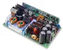
- 3.00” x 5.00” x 1.34”

- High Power Density 10.6 W/in3

- Up to 90% Efficiency

- 5 V Standby & 12 V Fan Outputs

- Active Current Share

- Remote On/Off

- Power Good Signal

- -10 ºC to +70 ºC Operation

- Universal AC Input 90-264 VAC

- Level B Conducted Emissions

- 48 VDC Input Versions Available (DMA212)

Designed for communications applications, the EMA212 has been developed to meet the needs of networking equipment, voice over IP systems, wireless LANs, servers, storage area networks and post-production broadcast equipment. Designers of these systems demand higher power from AC/DC units in industry-standard 1U formats as processing power and functionality grows within tight space constraints. The EMA212 delivers over 200W across the full universal AC input range from an industry-standard 3 x 5 inch (76.2 x 127 mm) footprint. It is 1.34 inches (34.04 mm) high and achieves 10.6 Watts per cubic inch power density without compromising performance or functionality.

With efficiency up to 90% at full load, the EMA212 needs only 12 CFM air-flow for full power operation at up to 50 °C ambient and will operate at up to 70 °C ambient with de-rating. The main output is 12, 24 or 48 VDC but each power supply also has a 5 V, 100 mA standby output and a 12 V, 1 A output for powering a fan. The unit incorporates a fully featured signal set including AC fail/DC OK, remote on/off and active current sharing.

xppower.com

## Models and Ratings

|Max Output Power<br>(12 CFM Air Flow)|Ouput Voltage<br>V1|Ouput Current<br>(12 CFM Airflow)|Fan Output<br>V2|Standby Supply<br>V3|Model<br>Number|
|---|---|---|---|---|---|
|212 W|12.0 VDC|16.7 A|12.0 V/1.0 A|5.0 V/0.1 A|EMA212PS12|
|212 W|24.0 VDC|8.3 A|12.0 V/1.0 A|5.0 V/0.1 A|EMA212PS24|
|205 W|48.0 VDC|4.0 A|12.0 V/1.0 A|5.0 V/0.1 A|EMA212PS48|


## Input Characteristics

|Characteristic|Minimum|Typical|Maximum|Units|Notes & Conditions|
|---|---|---|---|---|---|
|Input Voltage - Operating|90||264|VAC||
|Input Frequency|47|50/60|63|Hz||
|Power Factor||>0.9|||230 VAC|
|Input Current - No Load||110||mA||
|Input Current - Full Load||2.1/1.1||A|115/230 VAC|
|Inrush Current|||60|A|230 VAC cold start|
|Earth Leakage Current||0.5|1.1|mA|230/264 VAC 50 Hz|
|Input Protection|T5 A/250 V internal fuse in line|||||


## Output Characteristics

|Characteristic|Minimum|Typical|Maximum|Units|Notes & Conditions|
|---|---|---|---|---|---|
|Output Voltage - V1|12||48|VDC|See Models and Ratings table|
|Initial Set Accuracy|||±1(V1) , ±5(V2) & ±3(V3)|%||
|Output Voltage Adjustment|||||Not available|
|Minimum Load|||||No minimum load required|
|Start Up Delay||1.5|3|s|90 VAC full load (see fig. 1 to 3)|
|Start Up Rise Time|||20|ms||
|Hold Up Time|16|20||ms|90 VAC full load (see fig. 4 to 6)|
|Drift|||±0.2|%|After 20 min warm up|
|Line Regulation|||±0.5(V1), ±2(V2) & ±0.5(V3)|%||
|Load Regulation|||±1(V1), ±5(V2) & ±1(V3)|%|0-100% load V1 & V3, 10-100% load V2|
|Cross Regulation|||±10(V2)|%|10-100% load change V1|
|Transient Response - V1|||4|%|Recovery within 1% in less than 500 μs for a<br>25-75% and 75-25% load step (see fig. 7 & 8)|
|Over/Undershoot - V1|||2/5|%|12/48 V (see fig. 9)|
|Ripple & Noise|||1(V1 &V3) & 2(V2)|% pk-pk|20 MHz bandwidth (see fig. 11 to 14)|
|Overvoltage Protection|115||140|%|Vnom DC. Output 1 only, recycle input to reset|
|Overload Protection|110||140|% I nom|Output 1 only, auto reset (see fig. 10)|
|Short Circuit Protection|||||Trip & Restart (Hiccup mode)|
|Temperature Coefficient|||0.05|%/˚C||
|Overtemperature Protection||||°C|Primary & secondary protection|


2

xppower.com

## Start Up Delay From AC Turn On

**==> picture [303 x 197] intentionally omitted <==**

**----- Start of picture text -----**<br>
KEY<br>1 AC<br>2 V1<br>3 V FAN V2 1<br>4 V STANDBY V3<br>2<br>Figure 1<br>V1 (full load) - 1.40 s<br>**----- End of picture text -----**<br>


**==> picture [136 x 153] intentionally omitted <==**

**----- Start of picture text -----**<br>
1<br>3<br>Figure 2<br>V2 (full load) - 1.45 s<br>**----- End of picture text -----**<br>


**==> picture [118 x 151] intentionally omitted <==**

**----- Start of picture text -----**<br>
1<br>4<br>Figure 3<br>V3 (full load) - 344 ms<br>**----- End of picture text -----**<br>


3

xppower.com

## Hold Up Time From Loss Of AC

**==> picture [26 x 22] intentionally omitted <==**

**----- Start of picture text -----**<br>
KEY<br>1 AC<br>**----- End of picture text -----**<br>


**==> picture [93 x 53] intentionally omitted <==**

**----- Start of picture text -----**<br>
1<br>- | ae<br>**----- End of picture text -----**<br>


Figure 4 V1 21.2 ms (Full load at 90 VAC input)

**==> picture [4 x 5] intentionally omitted <==**

**----- Start of picture text -----**<br>
1<br>**----- End of picture text -----**<br>


Figure 5

V2 278 ms (Full load at 90 VAC input)

**==> picture [127 x 164] intentionally omitted <==**

**----- Start of picture text -----**<br>
1<br>H H : : :<br>LL ek<br>Door<br>¥ che 2¥<br>Figure 6<br>V3 1.12 s (Full load at 90 VAC input)<br>**----- End of picture text -----**<br>


4

xppower.com

## Output Transient Response 25-75% & 75-25% Load Step

**==> picture [50 x 18] intentionally omitted <==**

**----- Start of picture text -----**<br>
Figure 7<br>EMA212PS12<br>**----- End of picture text -----**<br>


**==> picture [49 x 18] intentionally omitted <==**

**----- Start of picture text -----**<br>
Figure 8<br>EMA212PS48<br>**----- End of picture text -----**<br>


## Output Overshoot

**==> picture [89 x 20] intentionally omitted <==**

**----- Start of picture text -----**<br>
Figure 9<br>Typical Output Overshoot<br>**----- End of picture text -----**<br>


Output Overload Characteristic

Unit enters trip and restart mode (hiccup mode)

**==> picture [249 x 144] intentionally omitted <==**

**----- Start of picture text -----**<br>
Vnom<br>-<br>-<br>a<br>——— -<br>7<br>a<br>7<br>><br>-<br>— //<br>0 100 140<br>% Load Current<br>Figure 10<br>Typical Overload Characteristic<br>Voltage<br>**----- End of picture text -----**<br>


5

xppower.com

## Output Ripple & Noise

Figure 11 V1 EMA212PS12 (Full load). 80 mV pk-pk Ripple. 20 MHz BW

Figure 13 V2 (Full load).

< 25 mV pk-pk Ripple. 20 MHz BW

Figure 12 V1 EMA212PS48 (Full load). 180 mV pk-pk Ripple. 20 MHz BW

Figure 14 V3 (Full load).

< 25 mV pk-pk Ripple. 20 MHz BW

6

xppower.com

## General Specifications

|Characteristic|Minimum<br>Typical<br>Maximum<br>Units<br>Notes & Conditions|
|---|---|
|Efficiency|88<br>%<br>Full load 230 VAC (see fig. 15 & 16)|
|Isolation: Input to Output|3000<br>VAC|
|Input to Ground|1500<br>VAC|
|Output to Ground|500<br>VDC|
|Switching Frequency: PFC<br>Main Converter<br>80<br>kHz<br>100<br>kHz<br>Power Density<br>10.6<br>W/in3<br>Mean Time Between Failure<br>212<br>kHrs<br>MIL-HDBK-217F, ground benign at 25°C.<br>Weight<br>0.66 (300)<br>lb (g)<br>~~=====—~~||
|||
|Characteristic|Notes & Conditions|
|Signals||
|Combined Power Fail<br>& DC OK|Open collector referenced to output 0V, transistor normally off when AC & output good.<br>Power Fail: Provides ≥5 ms warning of loss of output from AC failure.<br>DC OK: Provides warning of DC output failure (see fig. 17 to fig 27)|
|Remote On/Off|Uncommited isolated opto-coupler diode - powered diode inhibits the supply.|
|Current Share|For increased power, up to 3 supplies can be connected in parallel. Output current is shared within 10% at full load. Derate<br>to 90%. The current share function is not designed to offer redundant operation.|


## Efficiency Versus Load

**==> picture [520 x 409] intentionally omitted <==**

**----- Start of picture text -----**<br>
100.00% 100.00%<br>90.00% 90.00%<br>80.00% 80.00%<br>70.00% 70.00%<br>60.00% 60.00%<br>50.00% 50.00%<br>40.00% 40.00%<br>30.00% 30.00%<br>20.00% 20.00%<br>10.00% 10.00%<br>0.00% 0.00%<br>10% 20% 30% 40% 50% 60% 70% 80% 90% 100% 10% 20% 30% 40% 50% 60% 70% 80% 90% 100%<br>Load Load<br>Figure 15 Figure 16<br>EMA212PS12 EMA212PS48<br>Combined Power Fail & DC OK Signal Remote On/Off<br>Signal is an isolated control signal which can turn the PSU off by supplying<br>5 mA into the pin.<br>POWER SUPPLY 4-6 V POWER SUPPLY<br>Pin 8 CN3<br>5 V Standby   5 mA<br>330R<br>1K<br>Pin 6 CN3<br>Power Fail / DCOK Pin 4<br>Collector  CN3<br>0 V or Floating: PSU On<br>4-6 V: PSU Off<br>Transistor On (<0.8 V): Input & Output Not O<br>Power Fail / DCOK Transistor Off (>4.5 V): Input & Output OK 1K<br>Emitter<br>Pin 2 CN2-ve Return Pin 5<br>CN3<br>5 V Standby Rtn<br>Pin 9 CN3<br>0 V<br>e) Pin 2 CN2 (-ve)<br>Signal Connector<br>Figure 17<br>Efficiency Efficiency<br>**----- End of picture text -----**<br>


7

xppower.com

## Signals

**==> picture [144 x 38] intentionally omitted <==**

**----- Start of picture text -----**<br>
KEY<br>1 AC<br>2 Comined Power Fail & DC OK Signal<br>**----- End of picture text -----**<br>


**==> picture [416 x 513] intentionally omitted <==**

**----- Start of picture text -----**<br>
2 2<br>of |<br>1<br>1<br>To ee eae os.aey an oo che a eos<br>Figure 18 Figure 19<br>PF & DC OK signal ‘V’ AC switch on  PF & DC OK signal ‘V’ AC switch off<br>90 VAC full load - 2.8 seconds 90 VAC full load<br>GEIEE Single Seq 500 S$/s 0.000 voc Tek GEIB Single Seq SkSis<br>2<br>2<br>1 1<br>700 ch2 zi M500ms5Chi 5.92 cht 700 ¥ the zy HM SOms<br>Figure 20 Figure 21<br>PF & DC OK signal ‘V’ AC switch on PF & DC OK signal ‘V’ AC switch off<br>264 VAC full load - 1.4 seconds 264 VAC full load<br>**----- End of picture text -----**<br>


8

xppower.com

## Signals

**==> picture [214 x 150] intentionally omitted <==**

**----- Start of picture text -----**<br>
KEY<br>1 AC 2 V1 3 V FAN V2 4 V STANDBY V3<br>Tel GOIEE single Seq 1.25kSss5<br>2<br>: : : : : 1 : : :<br>**----- End of picture text -----**<br>


**==> picture [64 x 76] intentionally omitted <==**

**----- Start of picture text -----**<br>
2<br>: : 1<br>**----- End of picture text -----**<br>


**==> picture [35 x 8] intentionally omitted <==**

**----- Start of picture text -----**<br>
Figure 22<br>**----- End of picture text -----**<br>


**==> picture [147 x 8] intentionally omitted <==**

**----- Start of picture text -----**<br>
PF/DC OK signal ‘V’ V1 switch on full load<br>**----- End of picture text -----**<br>


**==> picture [148 x 20] intentionally omitted <==**

**----- Start of picture text -----**<br>
Figure 23<br>PF/DC OK signal ‘V’ V1 switch off full load<br>**----- End of picture text -----**<br>


**==> picture [409 x 155] intentionally omitted <==**

**----- Start of picture text -----**<br>
2 2<br>hop palling Tipe aeng be tinten<br>:::::<br>3 3<br>:: I : : : : : : : : I DONS : : : :<br>St the 2Y Me0oms che- 1.344 ch St the EY M 1oms<br>Figure 24 Figure 25<br>PF/DC OK signal ‘V’ V2 switch on full load  PF/DC OK signal ‘V’ V2 switch off full load<br>**----- End of picture text -----**<br>


**==> picture [69 x 81] intentionally omitted <==**

**----- Start of picture text -----**<br>
2<br>4<br>**----- End of picture text -----**<br>


**==> picture [67 x 71] intentionally omitted <==**

**----- Start of picture text -----**<br>
2<br>4<br>**----- End of picture text -----**<br>


**==> picture [150 x 19] intentionally omitted <==**

**----- Start of picture text -----**<br>
Figure 26<br>PF/DC OK signal ‘V’ V3 switch on full load<br>**----- End of picture text -----**<br>


**==> picture [149 x 20] intentionally omitted <==**

**----- Start of picture text -----**<br>
Figure 27<br>PF/DC OK signal ‘V’ V3 switch off full load<br>**----- End of picture text -----**<br>


9

~~eS~~ xppower.com ’ >

## XxxxxxxxxxEnvironmental

|Characteristic|Minimum|Typical|Maximum|Units|Notes & Conditions|
|---|---|---|---|---|---|
|Operating Temperature|-10||+70|şC|Derate linearly from +50 şC at 2.5%/şC<br>to 50% at 70 şC|
|Storage Temperature|-20||+85|şC||
|Cooling|12|||CFM|See Thermal Considerations.<br>No convection cooled rating|
|Humidity|5||95|%RH|Non-condensing|
|Operating Altitude|||3000|m||
|Shock|||30|g peak|Half sine 6 axes|
|Vibration|||2|g|5 Hz to 500 Hz, 3 axe s|


## Electromagnetic Compatibility - Immunity

|Phenomenon|Standard|Test Level|Criteria|Notes & Conditions|
|---|---|---|---|---|
|Harmonic Current|EN61000-3-2||Class A||
|EFT|EN61000-4-4|3|A||
|Surge|EN61000-4-5|3|A||
|Conducted|EN61000-4-6|10 V rms|A||
|||30% 10 ms|A||
|Dips and Interruptions|EN61000-4-11|60% 100 ms|B||
|||1000% 5000 ms|B||


## Electromagnetic Compatibility - Emissions

|Phenomenon|Standard|Test Level|Criteria|Notes & Conditions|
|---|---|---|---|---|
|Conducted|EN55022|Class B||See fig. 19|
|Radiated|EN55022|Class A|||
|Voltage Flicker|EN61000-3-3||||


Figure 19 Typical EMC plot

## Safety Agency Approvals

|Safety Agency|Safety Standard|Category|
|---|---|---|
|CB Report|CSA 155548-1790828 IEC60950-1:2001|Information Technology|
|CSA|CSA CERTIFICATE # 17980822 CSA 22.2 No. 60950-1-03|Information Technology|
|UL|UL File # E139109 UL60950-1 (2003)|Information Technology|
|TUV|TUV Certificate # B 07 03 57396 026 EN60950-1/A11:2004|Information Technology|
|CE|LVD||


10

xppower.com

## Mechanical Details

**==> picture [453 x 279] intentionally omitted <==**

**----- Start of picture text -----**<br>
5.00 (127.0)<br>0.22<br>(5.7) 4.55 (115.6)<br>CN3<br>6 5 CN2 CN2<br>1 1<br>10 1<br>TR11 2 2<br>TR4<br>(76.2)3.00 (64.8)2.55 C14 CN2<br>+ve<br>N -ve<br>(See Thermal<br>considerations) CN1<br>L<br>T7<br>C42<br>1.22 0.06<br>(31.0) (1.5)<br>ein 0.06 (1.5) ou<br>AIR FLOW SCREW 6.35 mm<br>12 CFM TYPE FASTONTYPE(2)<br>SAFETY EARTH - 4.8 mm Faston 4 X ø 0.14 (3.5) MOUNTING HOLES<br>**----- End of picture text -----**<br>


## **Notes**

## 1. All dimensions in inches (mm).

2. Units supplied with screw terminal (CN2) as standard. For faston type, add suffix ‘-F’  to the part number.

3. All 4 mounting positions should be connected to safety earth.

4. The air flow needs to be directed through the power supply within the end application.

## Pin Connections

**==> picture [379 x 127] intentionally omitted <==**

**----- Start of picture text -----**<br>
PIN CONNECTIONS - CN2 PIN CONNECTIONS - CN3<br>1 +V1 1 +V2<br>2 V1 Return 2 V2 Return<br>3 V2 Return<br>4 ROF<br>5 ROF Return<br>6 Power Fail/DC OK<br>7 Current Share<br>8 +V3<br>9 -V3 Mating Connectors:<br>10 +V2 CN1: Molex housing 09-50-3031 and crimp 2878.<br>a CN3: Molex housing 51110-1050 and crimp 50394-8100.<br>**----- End of picture text -----**<br>


11

xppower.com

## Thermal Considerations

|Temperature Measurements (Ambient ≤50 şC)<br>~~——_—_—==~~|Temperature Measurements (Ambient ≤50 şC)<br>~~——_—_—==~~|
|---|---|
|Component<br>~~——_~~|Max Temperature şC<br>~~——_—_—==~~|
|TR4 case<br>~~——_~~|110 şC<br>~~——_—_—==~~|
|C14<br>~~——_~~|105 şC<br>~~——_—_—==~~|
|C42<br>~~——_~~|105 şC<br>~~——_—_—==~~|
|TR11 case<br>~~——_~~|110 şC<br>~~——_—_—==~~|
|T7 coil<br>~~——_~~|120 şC<br>~~——_—_—==~~|


The estimated service life of the EMA212 is determined by the cooling arrangements and load conditions experienced in the end application. Due to the uncertain nature of the end application this estimated service life is based on the actual measured temperature of two key capacitors within the product when installed in the end application. The highest of the two component temperatures should be used.

The graph below expresses the estimated lifetime for a given component temperature and assumes continuous operation at this temperature.

## Estimated Service Life vs Component Temperature

**==> picture [288 x 149] intentionally omitted <==**

**----- Start of picture text -----**<br>
185000<br>165000<br>145000<br>125000<br>105000<br>85000<br>65000<br>45000<br>25000<br>5000 =z<br>105 95 85 75 65 55<br>C14 & 42 Temperature (°C)<br>Lifetime (Hrs)<br>**----- End of picture text -----**<br>


12

26-Sept-08
Updated at June 8, 2026
XP Power is a globally recognized leader in the design and manufacture of critical power solutions for the electronics industry. With a steadfast commitment to total quality and in-house engineering expertise, the company delivers highly reliable components that support complex applications across the industrial, healthcare, and technology sectors. Their extensive manufacturing capabilities provide engineers with a broad and dependable source for innovative power products. Our extensive portfolio of XP Power components is heavily focused on robust power and line protection. The core of this offering features a vast selection of high-performance AC/DC converters, designed to meet the rigorous efficiency and footprint demands of modern electronic systems. Complementing these are numerous reliable DC/DC converters, providing versatile options for precise voltage regulation and seamless system integration. Beyond their primary power conversion ranges, XP Power manufactures specialized components to address specific design challenges. Our selection includes essential passive components, such as power line filters for effective EMC and RFI suppression, ensuring signal integrity and strict regulatory compliance. Additionally, we provide dedicated AC/DC LED power supplies tailored for reliable, long-lasting performance in advanced commercial and industrial lighting applications.
About Novapart
Novapart is a B2B electronic component broker specialising in stock shortages and cost reduction. We source hard-to-find parts and identify compliant alternatives across a catalogue of 410,000+ components from 500+ manufacturers.
Learn more →Stock Shortage Specialist
When a component is unavailable, discontinued or has an unacceptable lead time, we tap into our network of vetted European and Asian distributors to source what you need — without compromising on quality or traceability.
Request a quote →Compliant Alternatives
We identify pin-to-pin, electrically equivalent substitutes that meet the same certifications (RoHS, AEC-Q100, REACH) as your original specification — validated against datasheets, not just part numbers. Often at a lower cost.
BOM Analysis service →