


ELL4FG150MA
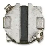
Power Inductor (SMD), 15 µH, 580 mA, Shielded, 600 mA, ELL-4FG Series
- Manufacturer: PANASONIC
- Product type: SMD Power Inductors
- Inductance:15µH; RMS Current (Irms):580mA; Inductor Construction:Shielded; Saturation Current (Isat):600mA; Product Range:-; DC Resistance Max:0.48ohm; Inductance Tolerance:± 20%; SVHC:
- Inductance: 15µH
- Product Range: ELL-4FG Series
- Product Width: 3.8mm
- Product Height: 1.1mm
- Product Length: 3.8mm
- DC Resistance Max: 0.48ohm
- RMS Current (Irms): 580mA
- Inductance Tolerance: ± 20%
- Inductor Construction: Shielded
- Inductor Case / Package: -
- Saturation Current (Isat): 600mA
| Delivery and price | |
|---|---|
| Units per pack | 4000 |
| Price | 0.215 € |
| Current stock | 10+ |
| Lead time | 30 days |
**Power Inductors**

## **Power Inductors / Wire Wound type**

## Series : **G**

## Type : **ELL4FG-A ELL4GG ELL4LG-A**

Type ELL4FG–A

Type ELL4GG Type ELL4LG–A

## po **Features**

- Magnetic shielded structure

- Low DC resistance and large current capability

- Shock resistant

- RoHS compliant

## Po **Recommended  Applications**

- DSC, Tablet terminal, Portable game device, DC/DC converter circuit for cellular phone

## po **Standard Packing Quantity**

- 2,000 pcs./reel (ELL4FG-A/ELL4GG)

- 3,000 pcs./reel (ELL4LG-A)

- **As for Soldering Conditions and Safety Precautions,**

   - Please see Data Files

**==> picture [469 x 350] intentionally omitted <==**

**----- Start of picture text -----**<br>
po Explanation of Part Numbers<br>1 2 3 4 5 6 7 8 9 10 11<br>E L L 4 F G 1 0 0 M<br>PJOUI LI U L UL og<br>Product Code Outer size Height Structure Inductance Tolerance Design No.<br>ELL Choke Coil (Magnetic shielded type ) F 1.2 max. G Series 2R2 → 2.2 µH M → ±20 % F A<br>G 1.4 max. 150 → 15 µH N → ±30 % G —<br>L 1.8 max. L A<br>ee Dimensions in mm (not to scale)<br>● ELL4FG-A ● ELL4GG 1.70<br>● ELL4LG-A Marking 1.60 Marking<br>0.70<br>1.20<br>3.80±0.2 C02 f 3.80±0.2 e Se 0.70<br>Type H<br>ELL4FG-A 1.1±0.10 (1.20 max.)<br>ELL4LG-A 1.80 max.<br>(5.00)<br>0<br>1.7<br>00<br>1.60 1.<br>00<br>1.<br>3.80±0.2 3.80±0.2<br>H 0.40<br>0.30 0.10<br>0.10 1.4 max.<br>**----- End of picture text -----**<br>


Design and specifications are each subject to change without notice.  Ask factory for the current technical specifications before purchase and/or use. Should a safety concern arise regarding this product, please be sure to contact us immediately.

02 Oct. 2014

**Power Inductors**

## Recommended land patterns in mm (not to scale)

● ELL4FG-A

● ELL4GG

|Series<br>._|Part No.<br>._~~==—=—==~~|Inductance<br>(100 kHz)<br>~~==—=—==~~|Inductance<br>(100 kHz)<br>~~==—=—==~~|RDC<br> (at 20 °C)<br>~~==—=—==~~|RDC<br> (at 20 °C)<br>~~==—=—==~~|Saturation Rated<br>Current✽1<br>(mA max.)<br>~~==—=—==~~|Temperature<br>Rise Current✽2<br>(mA max.)<br>~~==—=—==~~|Marking|
|---|---|---|---|---|---|---|---|---|
|||(µH)<br>~~==—=—==~~|Tol.<br>~~==—=—==~~|(mΩ)<br>~~==—=—==~~|Tol.<br>~~==—=—==~~||||
|Series<br>4FG-A<br>._|ELL4FG1R0NA<br>._~~==—=—==~~|1.0<br>~~==—=—==~~|±30 %<br>~~==—=—==~~|45<br>~~==—=—==~~|±20 %<br>~~==—=—==~~|1900<br>~~==—=—==~~|1950<br>~~==—=—==~~|01|
||ELL4FG1R5NA<br>._~~==—=—==~~|1.5<br>~~==—=—==~~||60<br>~~==—=—==~~||1600<br>~~==—=—==~~|1700<br>~~==—=—==~~|06|
||ELL4FG2R0NA<br>._~~==—=—==~~|2.0<br>~~==—=—==~~||70<br>~~==—=—==~~||1300<br>~~==—=—==~~|1550<br>~~==—=—==~~|10|
||ELL4FG3R3NA<br>._~~==—=—==~~|3.3<br>~~==—=—==~~||110<br>~~==—=—==~~||1100<br>~~==—=—==~~|1220<br>~~==—=—==~~|16|
||ELL4FG4R7NA<br>._~~==—=—==~~|4.7<br>~~==—=—==~~||160<br>~~==—=—==~~||1000<br>~~==—=—==~~|1000<br>~~==—=—==~~|21|
||ELL4FG6R8NA<br>._~~==—=—==~~|6.8<br>~~==—=—==~~||220<br>~~==—=—==~~||800<br>~~==—=—==~~|860<br>~~==—=—==~~|26|
||ELL4FG100MA|10.0|±20 %|290||700|750|31|
||ELL4FG150MA|15.0||480||600|580|33|
||ELL4FG220MA|22.0||620||420|500|36|
||ELL4FG330MA|33.0||1060||360|400|39|
||ELL4FG470MA|47.0||1600||290|330|51|
|Series<br>4GG|ELL4GG1R2N|1.2|±30 %|50|±20 %|2400|1900|03|
||ELL4GG1R8N|1.8||71||1900|1550|09|
||ELL4GG2R2N|2.2||88||1700|1400|11|
||ELL4GG3R3N|3.3||110||1500|1200|16|
||ELL4GG3R9N|3.9||120||1400|1150|19|
||ELL4GG4R7N|4.7||160||1200|1000|21|
||ELL4GG5R6N|5.6||170||1100|970|23|
||ELL4GG6R8N|6.8||200||1050|930|26|
||ELL4GG8R2N|8.2||220||1000|870|29|
||ELL4GG100M|10.0|±20 %|250||900|770|31|
||ELL4GG120M|12.0||380||800|650|32|
||ELL4GG150M|15.0||500||700|580|33|
||ELL4GG220M|22.0||640||600|500|36|
||ELL4GG330M|33.0||980||450|400|39|
||ELL4GG470M|47.0||1250||400|350|51|
||ELL4GG101M|100.0||2400||290|250|56|
|Series<br>4LG-A|ELL4LG1R0NA|1.0|±30 %|43|±20 %|2200|1900|01|
||ELL4LG1R5NA|1.5||48||1700|1800|06|
||ELL4LG2R2NA|2.2||55||1500|1700|11|
||ELL4LG2R7NA|2.7||63||1400|1550|13|
||ELL4LG3R3NA|3.3||72||1300|1450|16|
||ELL4LG4R7NA|4.7||90||1100|1300|21|
||ELL4LG6R2NA|6.2||140||930|1100|25|
||ELL4LG100MA|10.0|±20 %|200||800|950|31|
||ELL4LG150MA|15.0||300||620|730|33|
||ELL4LG220MA|22.0||390||550|640|36|
||ELL4LG330MA|33.0||610||430|510|39|
||ELL4LG470MA|47.0||920||360|410|51|
||ELL4LG680MA|68.0||1300||270|350|53|
||ELL4LG101MA|100.0||2200||250|260|56|
||ELL4LG151MA|150.0||3000||220|220|59|


- ✽1 Saturation Rated Current : This DC current which causes a 30 % inductance reduction from its nominal value.

- ✽2 Temperature Rise Current : This indicates the value of current when temperature rise dt/t= 40 °C (at 20 °C).

Design and specifications are each subject to change without notice.  Ask factory for the current technical specifications before purchase and/or use. Should a safety concern arise regarding this product, please be sure to contact us immediately.

02 Oct. 2014

**Power Inductors**

## **Embossed Carrier Tape Di men sions in mm (not to scale)**

2.00±0.05 t ~~o~~ 0.8 ~~f~~ 8.0±0.1 ~~0707-~~ 4.0±0.1 ~~09;~~ 0.4±0.1 | 0000000 A A[,] Tape running direction 0.8 ~~iatubat~~ 4.3±0.1 ~~rm~~ () Quantity 2,000 pcs./reel (ELL4FG-A/ELL4GG) ( ~~}—_—~~ Quantity 3,000 pcs./reel (ELL4LG-A) Type t A-A[,] Section ELL4FG-A 1.4±0.3 ELL4GG 1.6±0.3 ~~——~~ ELL4LG-A 2.0±0.3

Design and specifications are each subject to change without notice.  Ask factory for the current technical specifications before purchase and/or use. Should a safety concern arise regarding this product, please be sure to contact us immediately.

02 Oct. 2014

**Power Inductors**

## Safety Precautions

   - (Common precautions for Power Inductors / Wire Wound type)

- When using our products, no matter what sort of equipment they might be used for, be sure to make a written agreement on the specifications with us in advance. The design and specifications in this catalog are subject to change without prior notice.

- Do not use the products beyond the specifications described in this catalog.

- This catalog explains the quality and performance of the products as individual components. Be fore use, check and evaluate their operations when installed in your products.

- Install the following systems for a failsafe design to ensure safety if these products are to be used in equip ment where a defect in these products may cause the loss of human life or other significant damage, such as damage to vehicles (au to mo bile, train, vessel), traffic lights, medical equipment, aerospace equipment, elec tric heating ap pli anc es, com bus tion/gas equipment, rotating equipment, and disaster/crime prevention equip ment.

- ✽ Systems equipped with a protection circuit and a protection device

- ✽ Systems equipped with a redundant circuit or other system to prevent an unsafe status in the event of a single fault

## Precautions for use

## 1. Operation range and environments

- 1 These products are designed and manufactured for general and stan dard use in general elec tron ic equipment (e.g. AV equipment, home electric ap pli anc es, office equipment, information and com mu ni ca tion equipment)

- 2 These products are not intended for use in the following special conditions. Be fore using the products, care ful ly check the effects on their quality and performance, and determine whether or not they can be used.

   - In liquid, such as water, oil, chemicals, or organic solvent

   - In direct sunlight, outdoors, or in dust

   - In salty air or air with a high concentration of corrosive gas, such as Cl2, H2S, NH3, SO2, or NO2

   - In an environment where these products cause dew condensation

## 2. Handling

- 1 Do not bring magnets or magnetized materials close to the product. The influence of their magnetic field can change the inductance value.

- 2 Do not apply strong mechanical shocks by either dropping or collision with other parts. Excessive shock can damage the part.

## 3. Washing of board

- Kindly consult the Technical department before washing of the PWB with any cleansing agent, and provide the washing condition.

## 4. Resoldering with a soldering iron

The temperature of the tip of the soldering iron should be 360 °C or less, 4 seconds.

And resoldering with a soldering iron should be limited to 1 time, and after that should be cooling these.

## 5. Mounting side

External force must be less than 5.0 [N] : while mounting.

## 6. Storage conditions

Normal temperature (–5 to 35 °C),  normal humidity (85 % RH max.), shall not be exposed to direct sunlight and harmful gases and care should be taken so as not to cause dew.

## <Package markings>

Package markings include the product number, quantity, and country of origin. In principle, the country of origin should be indicated in English.

Design and specifications are each subject to change without notice.  Ask factory for the current technical specifications before purchase and/or use. Should a safety concern arise regarding this product, please be sure to contact us immediately.

02 Sep. 2014
Updated at June 7, 2026
Panasonic Industry is a global leader in the design and manufacture of high-quality electronic components. Renowned for a commitment to continuous innovation, the company provides the essential building blocks that empower modern engineering. From industrial automation to consumer electronics, Panasonic's components are trusted worldwide for their outstanding reliability, efficiency, and long-term performance. The extensive portfolio is anchored by a massive selection of passive components, featuring an industry-leading range of aluminium electrolytic, film, and polymer capacitors. Alongside these advanced capacitance solutions, engineers rely on Panasonic's robust power inductors and a highly versatile array of electromechanical devices, including solid-state, power, and signal relays engineered to excel in demanding environments. Beyond core passives and switching solutions, the offering encompasses critical circuit protection devices such as TVS varistors and NTC thermistors, as well as sophisticated thermal management materials. Panasonic also delivers precision light and motion sensors, highly reliable batteries, and advanced Bluetooth and WLAN connectivity modules, providing a comprehensive ecosystem of components to support next-generation technological design.
About Novapart
Novapart is a B2B electronic component broker specialising in stock shortages and cost reduction. We source hard-to-find parts and identify compliant alternatives across a catalogue of 410,000+ components from 500+ manufacturers.
Learn more →Stock Shortage Specialist
When a component is unavailable, discontinued or has an unacceptable lead time, we tap into our network of vetted European and Asian distributors to source what you need — without compromising on quality or traceability.
Request a quote →Compliant Alternatives
We identify pin-to-pin, electrically equivalent substitutes that meet the same certifications (RoHS, AEC-Q100, REACH) as your original specification — validated against datasheets, not just part numbers. Often at a lower cost.
BOM Analysis service →