
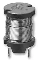


ELC12D681E
Choke, ELC-12D Series, 680 µH, 980 mA, 0.46 ohm, ± 10%
- Manufacturer: PANASONIC
- Product type: Radial Leaded Power Inductors
- Inductance: 680µH
- Product Range: ELC-12D
- DC Resistance Max: 0.46ohm
- RMS Current (Irms): 980mA
- Inductance Tolerance: ± 10%
- Inductor Construction: Unshielded
| Delivery and price | |
|---|---|
| Units per pack | 1 |
| Price | 0.26 € |
| Current stock | 10+ |
| Lead time | 30 days |
**Power Inductors**

## **Choke Coils**

## Series : **Pin terminal** Type : **09D, 11D, 12D, 16B, 18B, 10E, 12E, 15E, 18E**

Type 09D

**==> picture [120 x 8] intentionally omitted <==**

**----- Start of picture text -----**<br>
Type 11D  Type 12D<br>**----- End of picture text -----**<br>


Pin terminal inductors featuring small size and high performance

## **Features**

Type 16B

Type 18B

Type 10E–L

- High - µ and High Bm cores

- Wide inductor range

- Magnetic shield type (E Type)

- RoHS compliant

## **Recommended  Applications**

- Appliance, Offi ce automation equipment, Amusement machine, Power circuit for electric device

Type 12E–L

Type 15E–L Type 18E–L

**==> picture [430 x 214] intentionally omitted <==**

**----- Start of picture text -----**<br>
pe Explanation of Part Numbers<br>1 2 3 4 5 6 7 8 9 10 11<br>✽<br>E L C 0 9 D 2 R 2<br>PJOUF U U<br>Product code Style Construction Inductance Packaging Design No.<br>09 Core Core Taping D ✽ E, F etc.<br>D Case<br>11 a Terminal Terminal Other Omission<br>12 Core size Core<br>Terminal board B Terminal board<br>15 or Terminal<br>Case size Le<br>16 Core (Magnetic Shielded)<br>E Terminal board<br>18 Terminal<br>ee<br>Core<br>P<br>Direct terminal by wire<br>fe<br>**----- End of picture text -----**<br>


**==> picture [493 x 191] intentionally omitted <==**

**----- Start of picture text -----**<br>
Po Available I-L Characteristics<br>L (µH) L (µH)<br>10000 10000<br>5000 5000<br>10E 12E15E 18E<br>1000 1000<br>09D 16B 18B<br>500 500<br>100 100<br>50 PAST 50 EEN<br>10 10<br>51 IStt 51 EANEft<br>10 50 100 JTF 500 1000 ty 5000 10000 10 LE 50 100 500 1000 5000 10000<br>IDC(mA) IDC(mA)<br>**----- End of picture text -----**<br>


Design and specifications are each subject to change without notice.  Ask factory for the current technical specifications before purchase and/or use. Should a safety concern arise regarding this product, please be sure to contact us immediately.

02 Oct. 2014

**Power Inductors**

|~~e~~|Type<br>~~e~~s|Construction<br>|Extermal<br>Dimensions<br>D×H(mm)<br>|Inductance<br>(µH)<br>0.1<br>1.0<br>10<br>100<br>1000<br>10000<br>|Inductance<br>(µH)<br>0.1<br>1.0<br>10<br>100<br>1000<br>10000<br>|Inductance<br>(µH)<br>0.1<br>1.0<br>10<br>100<br>1000<br>10000<br>|Inductance<br>(µH)<br>0.1<br>1.0<br>10<br>100<br>1000<br>10000<br>|Inductance<br>(µH)<br>0.1<br>1.0<br>10<br>100<br>1000<br>10000<br>|Inductance<br>(µH)<br>0.1<br>1.0<br>10<br>100<br>1000<br>10000<br>|Inductance<br>(µH)<br>0.1<br>1.0<br>10<br>100<br>1000<br>10000<br>|Inductance<br>(µH)<br>0.1<br>1.0<br>10<br>100<br>1000<br>10000<br>|Inductance<br>(µH)<br>0.1<br>1.0<br>10<br>100<br>1000<br>10000<br>|Inductance<br>(µH)<br>0.1<br>1.0<br>10<br>100<br>1000<br>10000<br>|Current<br>IDC(A)<br>|
|---|---|---|---|---|---|---|---|---|---|---|---|---|---|---|
|Regular<br>~~e~~|09D<br>✽<br>~~e~~s~~nd~~|~~nd~~|09.5×8.9<br>(with case)<br>~~nd~~|~~nd~~|~~nd~~|2.2<br>~~nd~~||||~~nd~~|~~nd~~|~~nd~~|10000<br>~~nd~~|0.08 to 3.5<br>~~nd~~|
||||||||~~nd~~|||~~nd~~|~~nd~~|~~nd~~|||
|||||||||||~~nd~~|~~nd~~|10000<br>~~nd~~|||
||11D<br>✽<br>~~nd~~<br>~~hn~~|~~nd~~<br>~~hn~~|011.5×13.9<br>(with case)<br>~~nd~~<br>~~hn~~|~~nd~~<br>~~hn~~|~~nd~~<br>~~hn~~|2.2<br>~~nd~~<br>~~hn~~||||~~nd~~<br>~~hn~~|~~nd~~<br>~~hn~~|~~nd~~<br>~~hn~~|10000<br>~~nd~~<br>~~hn~~|0.16 to 5.3<br>~~nd~~<br>~~hn~~|
||||||||~~hn~~|||~~hn~~|~~hn~~|~~hn~~|||
|||||||||||~~hn~~|~~hn~~|10000<br>~~hn~~|||
||12D<br>~~hn~~<br>~~FD~~|~~hn~~<br>~~FD~~|012.5×16.5<br>~~hn~~<br>~~FD~~|~~hn~~<br>~~FD~~|~~hn~~<br>~~FD~~|~~hn~~<br>~~FD~~||||100<br>~~hn~~<br>~~FD~~|~~hn~~<br>~~FD~~|~~hn~~<br>~~FD~~|10000<br>~~hn~~<br>~~FD~~|0.27 to 1.9<br>~~hn~~<br>~~FD~~|
||||||||||||~~FD~~|~~FD~~|||
||||||||||||100<br>~~FD~~|10000<br>~~FD~~|||
||16B<br>~~FD~~<br>~~[~~<br>~~F~~|~~FD~~<br>~~[~~<br>~~Ft~~|016.0×23.0<br>~~FD~~<br>~~[i~~<br>~~t~~|~~FD~~<br>~~i~~<br>~~_~~|~~FD~~<br>~~i~~<br>~~_~~|3.3<br>~~FD~~<br>~~i~~<br>~~_~~||||~~FD~~<br>~~i~~|~~FD~~<br>~~iF~~|~~FD~~<br>~~F~~|10000<br>~~FD~~<br>~~F~~|0.26 to 8.5<br>~~FD~~<br>~~F~~|
|||||||||~~i~~||~~i~~|~~iF~~|~~F~~|||
|||||||||||~~i~~<br>~~_~~|~~iF~~<br>~~_~~|10000<br>~~F~~<br>~~_~~|||
||18B<br>~~[~~<br>~~F~~|~~[~~<br>~~Ft~~|020.0×27.0<br>~~[i~~<br>~~t~~|~~i~~<br>~~_~~|~~i~~<br>~~_~~|3.3<br>~~i~~<br>~~_~~||||~~i~~<br>~~_~~|~~iF~~<br>~~_~~|~~F~~<br>~~_~~|10000<br>~~F~~|0.36 to 8.5<br>~~F~~|
|||||||||~~_~~||~~_~~|~~_~~|~~_~~|||
|||||||||||~~_~~|~~_~~|10000<br>~~_~~|||
|Shield|10E–L<br>~~F~~<br>~~a~~|~~Ft~~<br>~~..~~|010.0×13.0<br>~~t ~~<br>~~..~~|~~_~~<br>~~..~~|~~_~~<br>~~..~~|3.9<br>~~_~~<br>~~..~~||||~~_~~<br>~~..~~|~~_~~<br>~~..~~|8200<br>~~_~~<br>~~..~~<br>~~|~~|8200<br>~~..~~<br>~~|~~|0.10 to 2.9<br>~~..~~<br>~~|~~|
|||||||||||~~_~~<br>~~..~~|~~_~~<br>~~..~~||||
|||||||||||~~..~~<br>~~|~~|~~..~~<br>~~|~~||||
||12E–L<br>~~a~~<br>~~[a~~|~~..~~<br>~~[a~~|013.0×18.5<br>~~..~~<br>~~[a~~|~~..~~<br>~~[a~~|~~..~~<br>~~[a~~|4.7<br>~~..~~<br>~~[a~~||||~~..~~<br>~~[a~~<br>~~|~~|~~..~~<br>~~[a~~<br>~~|~~|~~..~~<br>~~[a~~<br>~~|~~|10000<br>~~..~~<br>~~[a~~<br>~~|~~|0.13 to 4.4<br>~~..~~<br>~~[a~~<br>~~|~~|
||||||||||~~[a~~|~~[a~~<br>~~|~~|~~[a~~<br>~~|~~|~~[a~~<br>~~|~~|||
|||||||||||~~[a~~<br>~~|~~|~~[a~~<br>~~|~~|10000<br>~~[a~~<br>~~|~~|||
||15E–L<br>~~[a~~<br>~~CL~~|~~[a~~<br>~~CL~~|016.0×22.0<br>(3 pin terminal)<br>~~[a~~<br>~~CL.~~|~~[a~~<br>~~.~~|~~[a~~<br>~~.~~|5.6<br>~~[a~~<br>~~.~~||||~~[a~~<br>~~|~~<br>~~..~~|~~[a~~<br>~~|~~<br>~~.~~|~~[a~~<br>~~|~~<br>~~.~~|10000<br>~~[a~~<br>~~|~~<br>~~..~~|0.30 to 5.4<br>~~[a~~<br>~~|~~<br>~~.~~|
||||||||||~~.~~|~~..~~|~~.~~|~~.~~|||
|||||||||||~~..~~|~~.~~|10000<br>~~.~~|||
||18E–L<br>~~CL~~<br>~~ee~~|~~CL~~<br>~~ee~~|019.0×25.1<br>(4 pin terminal)<br>~~CL.~~<br>~~ee~~|~~.~~<br>~~ee~~|~~.~~<br>~~ee~~|5.6<br>~~.~~<br>~~ee~~||||~~..~~<br>~~ee~~|~~.~~<br>~~ee~~|~~.~~<br>~~ee~~|10000<br>~~..~~<br>~~ee~~|0.33 to 5.9<br>~~.~~<br>~~ee~~|
||||||||||~~ee~~|~~ee~~|~~ee~~|~~ee~~|||
|||||||||||~~ee~~|~~ee~~|10000<br>~~ee~~|||


Design and specifications are each subject to change without notice.  Ask factory for the current technical specifications before purchase and/or use. Should a safety concern arise regarding this product, please be sure to contact us immediately.

02 Oct. 2014

**Power Inductors**

## **Examples Type 09D**

**==> picture [491 x 676] intentionally omitted <==**

**----- Start of picture text -----**<br>
RDC.(Ω) IDC. [✽]<br>Inductance Tolerance Test Freq.<br>Part No. [at 20 °C] [at 20 °C]<br>(µH) (%) (kHz)<br>(Tol.±20 %) (A)max.<br>[Dimensions in mm] ELC09D2R2□F 2.2 0.012 3.50<br>(not to scale) ELC09D2R7□F 2.7 0.013 3.30<br>ELC09D3R3□F 3.3 0.015 3.20<br>f9.5 max. ELC09D3R9□F 3.9 0.016 3.10<br>ELC09D4R7□F 4.7 0.018 3.00<br>ELC09D5R6□F 5.6 0.019 2.90<br>±20<br>ELC09D6R8□F 6.8 0.021 2.80<br>ELC09D8R2□F 8.2 0.024 2.60<br>ELC09D100□F 10.0 0.027 2.50<br>ELC09D120□F 12.0 0.031 2.30<br>5.0±0.5 ELC09D150□F 15.0 0.035 2.10<br>2–f0.6<br>ELC09D180□F 18.0 0.038 2.00<br>ELC09D220□F 22.0 0.051 1.80<br>ELC09D270□F 27.0 0.058 1.60<br>ELC09D330□F 33.0 0.081 1.40<br>ELC09D390□F 39.0 0.087 1.30<br>ELC09D470□F 47.0 0.110 1.20<br>ELC09D560□F 56.0 0.130 1.10<br>ELC09D680□F 68.0 0.140 1.00<br>Recommended PWB<br>piercing plan ELC09D820□F 82.0 0.160 0.90<br>ELC09D101□F 100.0 0.200 0.82<br>ELC09D121□F 120.0 0.250 0.77<br>ELC09D151□F 150.0 10 0.320 0.74<br>ELC09D181□F 180.0 0.360 0.61<br>2–f1.00±0.05<br>ELC09D221□F 220.0 0.410 0.58<br>ELC09D271□F 270.0 0.500 0.52<br>5.0±0.1<br>ELC09D331□F 330.0 0.650 0.49<br>ELC09D391□F 390.0 0.860 0.46<br>ELC09D471□F 470.0 ±10 0.980 0.39<br>ELC09D561□F 560.0 1.100 0.36<br>ELC09D681□F 680.0 1.400 0.34<br>Connection Schematic<br>ELC09D821□F 820.0 1.600 0.30<br>ELC09D102□F 1000.0 2.100 0.28<br>ELC09D122□F 1200.0 2.400 0.23<br>ELC09D152□F 1500.0 2.800 0.21<br>S<br>ELC09D182□F 1800.0 3.800 0.19<br>ELC09D222□F 2200.0 4.400 0.17<br>ELC09D272□F 2700.0 6.100 0.16<br>F ELC09D332□F 3300.0 7.000 0.14<br>ELC09D392□F 3900.0 8.000 0.13<br>ELC09D472□F 4700.0 11.200 0.12<br>ELC09D562□F 5600.0 12.600 0.11<br>ELC09D682□F 6800.0 14.400 0.10<br>ELC09D822□F 8200.0 16.600 0.09<br>ELC09D103□F 10000.0 18.800 0.08<br>8.9 max.<br>4.0±1.0<br>**----- End of picture text -----**<br>


✽ Allowable DC Current: Smaller current value either when the inductance is –10 % or when the case temperature has risen 45 °C.

Design and specifications are each subject to change without notice.  Ask factory for the current technical specifications before purchase and/or use. Should a safety concern arise regarding this product, please be sure to contact us immediately.

02 Oct. 2014

**Power Inductors**

## **Examples Type 11D**

**==> picture [479 x 676] intentionally omitted <==**

**----- Start of picture text -----**<br>
R.DC.(Ω) IDC. [✽]<br>Inductance Tolerance Test Freq.<br>Part No. [at 20 °C] [at 20 °C]<br>(µH) (%) (kHz)<br>(Tol.±20 %) (A)max.<br>[Dimensions in mm] ELC11D2R2□F 2.2 0.013  5.30<br>(not to scale) ELC11D2R7□F 2.7 0.014  5.10<br>ELC11D3R3□F 3.3 0.015  4.90<br>f11.5 max. ELC11D3R9□F 3.9 0.016  4.80<br>ELC11D4R7□F 4.7 0.018  4.70<br>ELC11D5R6□F 5.6 0.020  4.60<br>±20<br>ELC11D6R8□F 6.8 0.022  4.40<br>ELC11D8R2□F 8.2 0.024  3.90<br>ELC11D100□F 10.0 0.029  3.50<br>ELC11D120□F 12.0 0.030  3.40<br>5.0±0.5 ELC11D150□F 15.0 0.033  3.30<br>2–f0.6<br>ELC11D180□F 18.0 0.037  3.10<br>ELC11D220□F 22.0 0.040  2.80<br>ELC11D270□F 27.0 0.048  2.70<br>ELC11D330□F 33.0 0.051  2.60<br>ELC11D390□F 39.0 0.057  2.50<br>ELC11D470□F 47.0 0.063  2.30<br>ELC11D560□F 56.0 0.071  2.10<br>ELC11D680□F 68.0 0.082  2.00<br>ELC11D820□F 82.0 0.090  1.90<br>Recommended PWB ELC11D101□F 100.0 0.120 1.80<br>piercing plan<br>ELC11D121□F 120.0 0.160 1.60<br>ELC11D151□F 150.0 10 0.180 1.40<br>2–f1.00±0.05 ELC11D181□F 180.0 0.200 1.30<br>ELC11D221□F 220.0 0.230 1.20<br>5.0±0.1 ELC11D271□F 270.0 0.320 1.10<br>ELC11D331□F 330.0 0.350 1.00<br>ELC11D391□F 390.0 0.400 0.95<br>ELC11D471□F 470.0 ±10 0.490 0.82<br>ELC11D561□F 560.0 0.620 0.73<br>ELC11D681□F 680.0 0.780 0.64<br>Connection Schematic<br>ELC11D821□F 820.0 0.870 0.62<br>ELC11D102□F 1000.0 1.100 0.57<br>ELC11D122□F 1200.0 1.200 0.52<br>ELC11D152□F 1500.0 1.700 0.43<br>S<br>ELC11D182□F 1800.0 2.000 0.40<br>ELC11D222□F 2200.0 2.300 0.38<br>ELC11D272□F 2700.0 2.800 0.34<br>F ELC11D332□F 3300.0 3.600 0.31<br>ELC11D392□F 3900.0 4.500 0.29<br>ELC11D472□F 4700.0 5.200 0.26<br>ELC11D562□F 5600.0 6.900 0.23<br>ELC11D682□F 6800.0 7.800 0.21<br>ELC11D822□F 8200.0 10.600  0.18<br>ELC11D103□F 10000.0 11.800 0.16<br>13.9 max.<br>4.0±1.0<br>**----- End of picture text -----**<br>


✽ Allowable DC Current: Smaller current value either when the inductance is –10 % or when the case temperature has risen 45 °C.

Design and specifications are each subject to change without notice.  Ask factory for the current technical specifications before purchase and/or use. Should a safety concern arise regarding this product, please be sure to contact us immediately.

02 Oct. 2014

**Power Inductors**

## **Examples Type 12D**

**==> picture [491 x 447] intentionally omitted <==**

**----- Start of picture text -----**<br>
RDC.(Ω) IDC. [✽]<br>Inductance Tolerance Test Freq.<br>Part No. [at 20 °C] [at 20 °C]<br>(µH) (%) (kHz)<br>(Tol.±20 %) (A)max.<br>ELC12D101E 100 0.150 1.90<br>[Dimensions in mm]<br>(not to scale) ELC12D121E 120 0.170 1.78<br>14.0 max.<br>f12.0±0.5 ELC12D151E 150 0.190 1.67<br>ELC12D181E 180 0.210 1.58<br>ELC12D221E 220 0.230 1.55<br>ELC12D271E 270 0.270 1.44<br>ELC12D331E 330 0.300 1.34<br>ELC12D391E 390 0.330 1.32<br>f0.8<br>7.5±0.5 ELC12D471E 470 0.380 1.25<br>ELC12D561E 560 0.420 1.15<br>ELC12D681E 680 0.460 0.98<br>ELC12D821E 820 0.650 0.94<br>ELC12D102E 1000 ±10 10 0.720 0.87<br>ELC12D122E 1200 0.830 0.86<br>Recommended PWB<br>piercing plan ELC12D152E 1500 1.270 0.64<br>2–f1.20±0.05 ELC12D182E 1800 1.330 0.63<br>ELC12D222E 2200 1.500 0.60<br>7.5±0.1 ELC12D272E 2700 1.890 0.54<br>ELC12D332E 3300 2.370 0.48<br>Connection Schematic ELC12D392E 3900 2.830 0.45<br>S ELC12D472E 4700 3.190 0.41<br>ELC12D562E 5600 4.080 0.34<br>ELC12D682E 6800 5.740 0.29<br>F ELC12D822E 8200 6.340 0.28<br>ELC12D103E 10000 7.200 0.27<br>16.5max.<br>3.5±0.8<br>**----- End of picture text -----**<br>


✽ Allowable DC Current: Smaller current value either when the inductance is –10 % or when the case temperature has risen 45 °C.

Design and specifications are each subject to change without notice.  Ask factory for the current technical specifications before purchase and/or use. Should a safety concern arise regarding this product, please be sure to contact us immediately.

02 Oct. 2014

**Power Inductors**

## **Examples Type 16B**

**==> picture [491 x 667] intentionally omitted <==**

**----- Start of picture text -----**<br>
Inductance Tolerance Test Freq. [at 20 °C]RDC.(Ω) IDC. [✽]<br>Part No. [at 20 °C]<br>(µH) (%) (kHz) (Tol.±30 %) [✽✽]<br>(A)max.<br>(Tol.±20 %)<br>[Dimensions in mm] ELC16B3R3L 3.3 0.012✽✽ 8.50<br>(not to scale) ELC16B3R9L 3.9 ±25 0.013✽✽ 8.00<br>ELC16B4R7L 4.7 0.015✽✽ 7.80<br>16.0 max. ELC16B5R6L 5.6 0.016✽✽ 7.40<br>f 13.0±0.5 ELC16B6R8L 6.8 0.018 6.70<br>ELC16B8R2L 8.2 0.019 6.10<br>±20<br>ELC16B100L 10.0 0.022 5.60<br>ELC16B120L 12.0 0.023 5.50<br>ELC16B150L 15.0 0.026 5.40<br>ELC16B180L 18.0 0.028 5.10<br>ELC16B220L 22.0 0.031 4.60<br>ELC16B270L 27.0 0.034 4.30<br>f 1.0<br>ELC16B330L 33.0 0.039 4.00<br>7.5±0.5<br>ELC16B390L 39.0 0.042 3.90<br>ELC16B470L 47.0 0.045 3.80<br>ELC16B560L 56.0 0.051 3.40<br>ELC16B680L 68.0 0.057 3.20<br>ELC16B820L 82.0 0.064 3.00<br>ELC16B101L 100.0 0.072 2.60<br>ELC16B121L 120.0 0.080 2.50<br>Recommended PWB<br>ELC16B151L 150.0 0.103 2.20<br>piercing plan<br>ELC16B181L 180.0 10 0.115 2.10<br>ELC16B221L 220.0 0.130 1.90<br>ELC16B271L 270.0 0.170 1.60<br>ELC16B331L 330.0 0.200 1.50<br>2–f 1.50±0.05 ELC16B391L 390.0 0.250 1.30<br>ELC16B471L 470.0 ±10 0.280 1.20<br>ELC16B561L 560.0 0.380 1.10<br>7.5±0.1<br>ELC16B681L 680.0 0.430 1.00<br>ELC16B821L 820.0 0.580 0.88<br>ELC16B102L 1000.0 0.660 0.85<br>ELC16B122L 1200.0 0.740 0.82<br>Connection Schematic ELC16B152L 1500.0 0.870 0.74<br>ELC16B182L 1800.0 1.220 0.60<br>ELC16B222L 2200.0 1.380 0.57<br>ELC16B272L 2700.0 1.570 0.54<br>S<br>ELC16B332L 3300.0 2.000 0.47<br>ELC16B392L 3900.0 2.400 0.42<br>ELC16B472L 4700.0 3.300 0.36<br>F ELC16B562L 5600.0 3.700 0.34<br>ELC16B682L 6800.0 4.200 0.32<br>ELC16B822L 8200.0 5.600 0.28<br>ELC16B103L 10000.0 6.400 0.26<br>23.0 max.<br>4.5±0.5<br>**----- End of picture text -----**<br>


✽ Allowable DC Current: Smaller current value either when the inductance is –10 % or when the case temperature has risen 45 °C.

Design and specifications are each subject to change without notice.  Ask factory for the current technical specifications before purchase and/or use. Should a safety concern arise regarding this product, please be sure to contact us immediately.

02 Oct. 2014

**Power Inductors**

## **Examples Type 18B**

**==> picture [491 x 667] intentionally omitted <==**

**----- Start of picture text -----**<br>
RDC.(Ω) IDC. [✽]<br>Inductance Tolerance Test Freq.<br>Part No. [at 20 °C] [at 20 °C]<br>(µH) (%) (kHz)<br>(Tol.±20 %) (A)max.<br>[Dimensions in mm] ELC18B3R3L 3.3 0.010 8.50<br>(not to scale) ELC18B3R9L 3.9 0.011 8.00<br>ELC18B4R7L 4.7 0.012 7.80<br>20.0 max.<br>ELC18B5R6L 5.6 0.013 7.40<br>f 16.0 max.<br>ELC18B6R8L 6.8 0.015 6.80<br>±20<br>ELC18B8R2L 8.2 0.016 6.60<br>ELC18B100L 10.0 0.017 6.50<br>ELC18B120L 12.0 0.018 6.00<br>ELC18B150L 15.0 0.021 5.90<br>ELC18B180L 18.0 0.022 5.60<br>ELC18B220L 22.0 0.025 5.40<br>ELC18B270L 27.0 0.028 4.80<br>ELC18B330L 33.0 0.030 4.60<br>f 1.0<br>ELC18B390L 39.0 0.033 4.40<br>7.5±0.5<br>ELC18B470L 47.0 0.037 4.30<br>ELC18B560L 56.0 0.040 4.20<br>ELC18B680L 68.0 0.046 4.00<br>ELC18B820L 82.0 0.051 3.70<br>ELC18B101L 100.0 0.057 3.20<br>ELC18B121L 120.0 0.065 3.00<br>Recommended PWB<br>ELC18B151L 150.0 0.072 2.70<br>piercing plan<br>ELC18B181L 180.0 10 0.082 2.60<br>ELC18B221L 220.0 0.090 2.40<br>ELC18B271L 270.0 0.110 2.20<br>ELC18B331L 330.0 0.130 1.90<br>2–f 1.50±0.05 ELC18B391L 390.0 0.150 1.80<br>ELC18B471L 470.0 ±10 0.210 1.60<br>7.5±0.1 ELC18B561L 560.0 0.230 1.50<br>ELC18B681L 680.0 0.260 1.40<br>ELC18B821L 820.0 0.340 1.30<br>ELC18B102L 1000.0 0.390 1.10<br>ELC18B122L 1200.0 0.440 1.00<br>Connection Schematic ELC18B152L 1500.0 0.580 0.85<br>ELC18B182L 1800.0 0.650 0.84<br>ELC18B222L 2200.0 0.880 0.75<br>ELC18B272L 2700.0 1.200 0.68<br>S<br>ELC18B332L 3300.0 1.400 0.60<br>ELC18B392L 3900.0 1.500 0.57<br>ELC18B472L 4700.0 1.700 0.55<br>F ELC18B562L 5600.0 2.200 0.46<br>ELC18B682L 6800.0 2.800 0.45<br>ELC18B822L 8200.0 3.100 0.41<br>ELC18B103L 10000.0 3.900 0.36<br>27.0 max.<br>5.0±1<br>18.0 max.<br>f<br>**----- End of picture text -----**<br>


✽ Allowable DC Current: Smaller current value either when the inductance is –10 % or when the case temperature has risen 45 °C.

Design and specifications are each subject to change without notice.  Ask factory for the current technical specifications before purchase and/or use. Should a safety concern arise regarding this product, please be sure to contact us immediately.

02 Oct. 2014

**Power Inductors**

**==> picture [489 x 150] intentionally omitted <==**

**----- Start of picture text -----**<br>
Tape Dimensions in mm for Type 09D (not to scale) Tape Dimensions in mm for Type 11D (not to scale)<br>f9.5 max. 1.3 max. 1.3 max. 2.0 max. 2.0 max. f11.5 max. 1.3 max. 1.3 max. 2.0 max. 2.0 max.<br>Marking 12.7 Marking 12.7<br>3.85 5.0 3.85 5.0<br>0.6 0.6<br>12.7 5.0±1.0 f4.0 runningTape 12.7 5.0±1.0 f4.0 runningTape<br>direction direction<br>500 pcs./reel 500 pcs./reel<br>18.0 8.9 max. 3.0 max. 801. 13.9 max. 3.0 max.<br>9.0 9.0<br>11.0 max. 5.0 min. 18.0 11.0 max. 5.0 min. 18.0<br>1.0 max. 1.0 max.<br>**----- End of picture text -----**<br>


## Safety Precautions

- When using our products, no matter what sort of equipment they might be used for, be sure to make a written agreement on the specifications with us in advance. The design and specifications in this catalog are subject to change without prior notice.

- Do not use the products beyond the specifications described in this catalog.

- This catalog explains the quality and performance of the products as individual components. Be fore use, check and evaluate their operations when installed in your products.

- Install the following systems for a failsafe design to ensure safety if these products are to be used in equip ment where a defect in these products may cause the loss of human life or other significant damage, such as damage to vehicles (au to mo bile, train, vessel), traffic lights, medical equipment, aerospace equipment, elec tric heating ap pli anc es, com bus tion/gas equipment, rotating equipment, and disaster/crime prevention equip ment.

- ✽ Systems equipped with a protection circuit and a protection device

- ✽ Systems equipped with a redundant circuit or other system to prevent an unsafe status in the event of a single fault

## Precautions for use

## 1. Rated current

The rated current is defined as the smaller value of ei ther the current value when the inductance drops 10 % down from its initial point, or when the average temperature of coil interior rises 45 °C up on pow er source. Do not operate these coils beyond the specified rat ed current.

## 2. Mounting

- 1 Cores may be damaged when ex ces sive force or shock is applied. Do not use products which may have been dropped.

- 2 Be careful not to make contact with other parts and consider possible interaction between coils due to magnetic interference.

- 3 Be careful of being too close to heat-radiating parts (high temperature).

- 4 Do not bend the pin-terminals during assembly.

   - The pin-terminals must connect correctly.

   - Do not apply them a shock to avoid causing an open or short circuit condition.

- 5 The float on PWB must not be after mounting.

## 3. Soldering

- 1 Use flux which will not effect copper wire. (Be sure to use proper amounts of chloride, pH and other solvents) 2 When using a soldering iron, wait at least 3 minutes before attempting to re-solder.

## 4. Storage

- 1 Avoid high temperatures, high moisture, gases and magnetic fields.

- 2 For long term storage of more than 1 year, use the prod ucts only after inspecting their outer structure. (Look for possible rusting of the core and oxidation of the lead wire, which would affect its solderability.)

## <Package markings>

Package markings include the product number, quantity, and country of origin. In principle, the country of origin should be indicated in English.

Design and specifications are each subject to change without notice.  Ask factory for the current technical specifications before purchase and/or use. Should a safety concern arise regarding this product, please be sure to contact us immediately.

02 Oct. 2014
Updated at February 9, 2023
Panasonic Industry is a global leader in the design and manufacture of high-quality electronic components. Renowned for a commitment to continuous innovation, the company provides the essential building blocks that empower modern engineering. From industrial automation to consumer electronics, Panasonic's components are trusted worldwide for their outstanding reliability, efficiency, and long-term performance. The extensive portfolio is anchored by a massive selection of passive components, featuring an industry-leading range of aluminium electrolytic, film, and polymer capacitors. Alongside these advanced capacitance solutions, engineers rely on Panasonic's robust power inductors and a highly versatile array of electromechanical devices, including solid-state, power, and signal relays engineered to excel in demanding environments. Beyond core passives and switching solutions, the offering encompasses critical circuit protection devices such as TVS varistors and NTC thermistors, as well as sophisticated thermal management materials. Panasonic also delivers precision light and motion sensors, highly reliable batteries, and advanced Bluetooth and WLAN connectivity modules, providing a comprehensive ecosystem of components to support next-generation technological design.
About Novapart
Novapart is a B2B electronic component broker specialising in stock shortages and cost reduction. We source hard-to-find parts and identify compliant alternatives across a catalogue of 410,000+ components from 500+ manufacturers.
Learn more →Stock Shortage Specialist
When a component is unavailable, discontinued or has an unacceptable lead time, we tap into our network of vetted European and Asian distributors to source what you need — without compromising on quality or traceability.
Request a quote →Compliant Alternatives
We identify pin-to-pin, electrically equivalent substitutes that meet the same certifications (RoHS, AEC-Q100, REACH) as your original specification — validated against datasheets, not just part numbers. Often at a lower cost.
BOM Analysis service →