
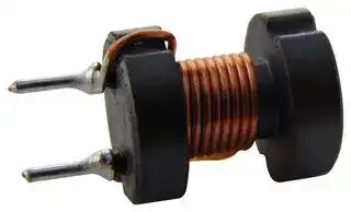


ELC10D391E
Choke, ELC-10D Series, 390 µH, 800 mA, 0.4 ohm, ± 10%
- Manufacturer: PANASONIC
- Product type: Radial Leaded Power Inductors
- Product Range:ELC-10D Series; Inductance:390µH; RMS Current (Irms):800mA; Saturation Current (Isat):-; DC Resistance Max:0.4ohm; Inductance Tolerance:± 10%; SVHC:No SVHC (12-Jan-2017); Body
- SVHC: To Be Advised
- Inductance: 390µH
- Product Range: ELC-10D Series
- DC Resistance Max: 0.4ohm
- RMS Current (Irms): 800mA
- Inductance Tolerance: ± 10%
- Inductor Construction: -
- Saturation Current (Isat): -
| Delivery and price | |
|---|---|
| Units per pack | 1000 |
| Price | 0.305 € |
| Current stock | 10+ |
| Lead time | 30 days |
Choke Coils

## ■ Examples Type 06D

|Choke Coils|Choke Coils|Choke Coils|Choke Coils|Choke Coils|Choke Coils|Choke Coils|
|---|---|---|---|---|---|---|
|■Examples Type 06D|||||||
||Part No.|Inductance<br>(µH)|Tolerance<br>(%)|Test Freq.<br>(kHz)|RDC.(�)<br>[at 20 °C]<br>✽✽(Tol.±30 %)<br>(Tol.±20 %)|✽IDC.<br>[at 20 °C]<br>(A)max.|
|f6.7 max.<br>10.5 max.<br>4.0±1.2<br>3.0±0.5<br>f0.65<br>3.0±0.1<br>2-f1.00±0.05<br>S<br>F<br>[Dimensions in mm]<br>(not to scale)<br>Recommended PWB<br>piercing plan<br>Connection Schematic|ELC06D2R2E|2.2|±20|10|✽✽0.026|3.400|
||ELC06D2R7E|2.7|||✽✽0.028|3.200|
||ELC06D3R3E|3.3|||✽✽0.027|3.000|
||ELC06D3R9E|3.9|||✽✽0.030|2.800|
||ELC06D4R7E|4.7|||✽✽0.033|2.600|
||ELC06D5R6E|5.6|||✽✽0.035|2.400|
||ELC06D6R8E|6.8|||0.041|2.000|
||ELC06D8R2E|8.2|||0.048|1.800|
||ELC06D100E|10.0|||0.052|1.700|
||ELC06D120E|12.0|||0.054|1.650|
||ELC06D150E|15.0|||0.059|1.500|
||ELC06D180E|18.0|||0.065|1.250|
||ELC06D220E|22.0|±10||0.076|1.200|
||ELC06D270E|27.0|||0.083|0.950|
||ELC06D330E|33.0|||0.100|0.900|
||ELC06D390E|39.0|||0.105|0.850|
||ELC06D470E|47.0|||0.120|0.800|
||ELC06D560E|56.0|||0.140|0.750|
||ELC06D680E|68.0|||0.150|0.700|
||ELC06D820E|82.0|||0.210|0.550|
||ELC06D101E|100.0|||0.230|0.500|
||ELC06D121E|120.0|||0.260|0.490|
||ELC06D151E|150.0|||0.370|0.450|
||ELC06D181E|180.0|||0.420|0.400|
||ELC06D221E|220.0|||0.550|0.360|
||ELC06D271E|270.0|||0.650|0.350|
||ELC06D331E|330.0|||0.740|0.300|
||ELC06D391E|390.0|||0.950|0.270|
||ELC06D471E|470.0|||1.080|0.240|
||ELC06D561E|560.0|||1.220|0.220|
||ELC06D681E|680.0|||1.590|0.210|
||ELC06D821E|820.0|||1.760|0.180|
||ELC06D102E|1000.0|||2.490|0.160|
||ELC06D122E|1200.0|||2.760|0.150|
||ELC06D152E|1500.0|||3.240|0.130|
||ELC06D182E|1800.0|||4.560|0.120|
||ELC06D222E|2200.0|||5.180|0.110|
||ELC06D272E|2700.0|||6.080|0.100|
||ELC06D332E|3300.0|||8.800|0.100|
||ELC06D392E|3900.0|||9.470|0.080|
||ELC06D472E|4700.0|||10.900|0.075|
||ELC06D562E|5600.0|||12.300|0.070|
|✽Allowable DC Current: Smaller current value either when the inductance is –10 % or when the case temperature has risen 45 °C.|||||||


✽ Allowable DC Current: Smaller current value either when the inductance is –10 % or when the case temperature has risen 45 °C.

Design and specifi cations are each subject to change without notice.  Ask factory for the current technical specifi cations before purchase and/or use. Should a safety concern arise regarding this product, please be sure to contact us immediately.

Feb. 2006

Choke Coils

## ■ Examples Type 09D

|Choke Coils|Choke Coils|Choke Coils|Choke Coils|Choke Coils|Choke Coils|Choke Coils|
|---|---|---|---|---|---|---|
|■Examples Type 09D|||||||
||Part No.|Inductance<br>(µH)|Tolerance<br>(%)|Test Freq.<br>(kHz)|RDC.(�)<br>[at 20 °C]<br>✽✽(Tol.±30 %)<br>(Tol.±20 %)|✽IDC.<br>[at 20 °C]<br>(A)max.|
|f9.5 max.<br>8.9 max.<br>4.0±1.0<br>5.0±0.5<br>2–f0.6<br>5.0±0.1<br>2–f1.00±0.05<br>S<br>F<br>[Dimensions in mm]<br>(not to scale)<br>Recommended PWB<br>piercing plan<br>Connection Schematic|ELC09D2R2�F|2.2|±20|10|0.012|3.50|
||ELC09D2R7�F|2.7|||0.013|3.30|
||ELC09D3R3�F|3.3|||0.015|3.20|
||ELC09D3R9�F|3.9|||0.016|3.10|
||ELC09D4R7�F|4.7|||0.018|3.00|
||ELC09D5R6�F|5.6|||0.019|2.90|
||ELC09D6R8�F|6.8|||0.021|2.80|
||ELC09D8R2�F|8.2|||0.024|2.60|
||ELC09D100�F|10.0|||0.027|2.50|
||ELC09D120�F|12.0|||0.031|2.30|
||ELC09D150�F|15.0|||0.035|2.10|
||ELC09D180�F|18.0|||0.038|2.00|
||ELC09D220�F|22.0|±10||0.051|1.80|
||ELC09D270�F|27.0|||0.058|1.60|
||ELC09D330�F|33.0|||0.081|1.40|
||ELC09D390�F|39.0|||0.087|1.30|
||ELC09D470�F|47.0|||0.110|1.20|
||ELC09D560�F|56.0|||0.130|1.10|
||ELC09D680�F|68.0|||0.140|1.00|
||ELC09D820�F|82.0|||0.160|0.90|
||ELC09D101�F|100.0|||0.200|0.82|
||ELC09D121�F|120.0|||0.250|0.77|
||ELC09D151�F|150.0|||0.320|0.74|
||ELC09D181�F|180.0|||0.360|0.61|
||ELC09D221�F|220.0|||0.410|0.58|
||ELC09D271�F|270.0|||0.500|0.52|
||ELC09D331�F|330.0|||0.650|0.49|
||ELC09D391�F|390.0|||0.860|0.46|
||ELC09D471�F|470.0|||0.980|0.39|
||ELC09D561�F|560.0|||1.100|0.36|
||ELC09D681�F|680.0|||1.400|0.34|
||ELC09D821�F|820.0|||1.600|0.30|
||ELC09D102�F|1000.0|||2.100|0.28|
||ELC09D122�F|1200.0|||2.400|0.23|
||ELC09D152�F|1500.0|||2.800|0.21|
||ELC09D182�F|1800.0|||3.800|0.19|
||ELC09D222�F|2200.0|||4.400|0.17|
||ELC09D272�F|2700.0|||6.100|0.16|
||ELC09D332�F|3300.0|||7.000|0.14|
||ELC09D392�F|3900.0|||8.000|0.13|
||ELC09D472�F|4700.0|||11.200|0.12|
||ELC09D562�F|5600.0|||12.600|0.11|
||ELC09D682�F|6800.0|||14.400|0.10|
||ELC09D822�F|8200.0|||16.600|0.09|
||ELC09D103�F|10000.0|||18.800|0.08|
|✽Allowable DC Current: Smaller current value either when the inductance is –10 % or when the case temperature has risen 45 °C.|||||||


✽ Allowable DC Current: Smaller current value either when the inductance is –10 % or when the case temperature has risen 45 °C.

Design and specifi cations are each subject to change without notice.  Ask factory for the current technical specifi cations before purchase and/or use. Should a safety concern arise regarding this product, please be sure to contact us immediately.

Feb. 2006

Choke Coils

## ■ Examples Type 10D

|Choke Coils|Choke Coils|Choke Coils|Choke Coils|Choke Coils|Choke Coils|Choke Coils|
|---|---|---|---|---|---|---|
|■Examples Type 10D|||||||
||Part No.|Inductance<br>(µH)|Tolerance<br>(%)|Test Freq.<br>(kHz)|RDC.(�)<br>[at 20 °C]<br>(Tol.±20 %)|✽IDC.<br>[at 20 °C]<br>(A)max.|
|f10.0±0.5<br>13.0 max.<br>5.0±0.5<br>f0.8<br>4.0 –1.0<br>+1.5<br>15.0 max.<br>2–f1.20±0.05<br>5.0±0.1<br>S<br>F<br>Recommended PWB<br>piercing plan<br>Connection Schematic<br>[Dimensions in mm]<br>(not to scale)|ELC10D2R2E|2.2|±20|10|0.014|5.90|
||ELC10D2R7E|2.7|||0.015|5.50|
||ELC10D3R3E|3.3|||0.016|5.20|
||ELC10D3R9E|3.9|||0.018|4.80|
||ELC10D4R7E|4.7|||0.019|4.60|
||ELC10D5R6E<br>ELC10D6R8E|5.6<br>6.8|||0.021<br>0.022|4.30<br>4.20|
||ELC10D8R2E|8.2|||0.024|4.00|
||ELC10D100E|10.0|||0.026|3.90|
||ELC10D120E|12.0|||0.028|3.80|
||ELC10D150E|15.0|||0.033|3.50|
||ELC10D180E|18.0|||0.036|3.40|
||ELC10D220E|22.0|±10||0.040|3.20|
||ELC10D270E|27.0|||0.044|3.00|
||ELC10D330E|33.0|||0.051|2.80|
||ELC10D390E|39.0|||0.054|2.70|
||ELC10D470E|47.0|||0.060|2.50|
||ELC10D560E|56.0|||0.067|2.30|
||ELC10D680E|68.0|||0.075|2.10|
||ELC10D820E|82.0|||0.095|1.80|
||ELC10D101E|100.0|||0.110|1.70|
||ELC10D121E|120.0|||0.120|1.60|
||ELC10D151E|150.0|||0.160|1.40|
||ELC10D181E|180.0|||0.180|1.30|
||ELC10D221E|220.0|||0.210|1.10|
||ELC10D271E|270.0|||0.280|1.00|
||ELC10D331E|330.0|||0.320|0.90|
||ELC10D391E|390.0|||0.400|0.80|
||ELC10D471E|470.0|||0.450|0.70|
||ELC10D561E|560.0|||0.560|0.68|
||ELC10D681E|680.0|||0.660|0.64|
||ELC10D821E|820.0|||0.800|0.55|
||ELC10D102E|1000.0|||1.000|0.50|
||ELC10D122E|1200.0|||1.200|0.45|
||ELC10D152E|1500.0|||1.500|0.42|
||ELC10D182E|1800.0|||1.800|0.40|
||ELC10D222E|2200.0|||2.100|0.36|
||ELC10D272E|2700.0|||2.700|0.32|
||ELC10D332E|3300.0|||3.200|0.28|
||ELC10D392E|3900.0|||3.500|0.26|
|✽Allowable DC Current: Smaller current value either when the inductance is –10 % or when the case temperature has risen 45 °C.|||||||


✽ Allowable DC Current: Smaller current value either when the inductance is –10 % or when the case temperature has risen 45 °C.

Design and specifi cations are each subject to change without notice.  Ask factory for the current technical specifi cations before purchase and/or use. Should a safety concern arise regarding this product, please be sure to contact us immediately.

Feb. 2006

Choke Coils

## ■ Examples Type 11D

|Choke Coils|Choke Coils|Choke Coils|Choke Coils|Choke Coils|Choke Coils|Choke Coils|
|---|---|---|---|---|---|---|
|■Examples Type 11D|||||||
||Part No.|Inductance<br>(µH)|Tolerance<br>(%)|Test Freq.<br>(kHz)|RDC.(�)<br>[at 20 °C]<br>(Tol.±20 %)|✽IDC.<br>[at 20 °C]<br>(A)max.|
|f11.5 max.<br>13.9 max.<br>4.0±1.0<br>5.0±0.5<br>2–f0.6<br>5.0±0.1<br>2–f1.00±0.05<br>S<br>F<br>Recommended PWB<br>piercing plan<br>Connection Schematic<br>[Dimensions in mm]<br>(not to scale)|ELC11D2R2F|2.2|±20|10|0.013|5.30|
||ELC11D2R7F|2.7|||0.014|5.10|
||ELC11D3R3F|3.3|||0.015|4.90|
||ELC11D3R9F|3.9|||0.016|4.80|
||ELC11D4R7F|4.7|||0.018|4.70|
||ELC11D5R6F|5.6|||0.020|4.60|
||ELC11D6R8F|6.8|||0.022|4.40|
||ELC11D8R2F|8.2|||0.024|3.90|
||ELC11D100F|10.0|||0.029|3.50|
||ELC11D120F|12.0|||0.030|3.40|
||ELC11D150F|15.0|||0.033|3.30|
||ELC11D180F|18.0|||0.037|3.10|
||ELC11D220F|22.0|±10||0.040|2.80|
||ELC11D270F|27.0|||0.048|2.70|
||ELC11D330F|33.0|||0.051|2.60|
||ELC11D390F|39.0|||0.057|2.50|
||ELC11D470F|47.0|||0.063|2.30|
||ELC11D560F|56.0|||0.071|2.10|
||ELC11D680F|68.0|||0.082|2.00|
||ELC11D820F|82.0|||0.090|1.90|
||ELC11D101F|100.0|||0.120|1.80|
||ELC11D121F|120.0|||0.160|1.60|
||ELC11D151F|150.0|||0.180|1.40|
||ELC11D181F|180.0|||0.200|1.30|
||ELC11D221F|220.0|||0.230|1.20|
||ELC11D271F|270.0|||0.320|1.10|
||ELC11D331F|330.0|||0.350|1.00|
||ELC11D391F|390.0|||0.400|0.95|
||ELC11D471F|470.0|||0.490|0.82|
||ELC11D561F|560.0|||0.620|0.73|
||ELC11D681F|680.0|||0.780|0.64|
||ELC11D821F|820.0|||0.870|0.62|
||ELC11D102F|1000.0|||1.100|0.57|
||ELC11D122F|1200.0|||1.200|0.52|
||ELC11D152F|1500.0|||1.700|0.43|
||ELC11D182F|1800.0|||2.000|0.40|
||ELC11D222F|2200.0|||2.300|0.38|
||ELC11D272F|2700.0|||2.800|0.34|
||ELC11D332F|3300.0|||3.600|0.31|
||ELC11D392F|3900.0|||4.500|0.29|
||ELC11D472F|4700.0|||5.200|0.26|
||ELC11D562F|5600.0|||6.900|0.23|
||ELC11D682F|6800.0|||7.800|0.21|
||ELC11D822F|8200.0|||10.600|0.18|
||ELC11D103F|10000.0|||11.800|0.16|
|✽Allowable DC Current: Smaller current value either when the inductance is –10 % or when the case temperature has risen 45 °C.|||||||


✽ Allowable DC Current: Smaller current value either when the inductance is –10 % or when the case temperature has risen 45 °C.

Design and specifi cations are each subject to change without notice.  Ask factory for the current technical specifi cations before purchase and/or use. Should a safety concern arise regarding this product, please be sure to contact us immediately.

Feb. 2006

Choke Coils

## ■ Examples Type 11P

|Choke Coils|Choke Coils|Choke Coils|Choke Coils|Choke Coils|Choke Coils|Choke Coils|Choke Coils|Choke Coils|Choke Coils|Choke Coils|Choke Coils|
|---|---|---|---|---|---|---|---|---|---|---|---|
|■Examples Type 11P||||||||||||
|||Part No.|Inductance<br>(µH)|Tolerance<br>(%)|Test Freq.<br>(kHz)||RDC.(�)<br>[at 20 °C]<br>(Tol.±20 %)||✽IDC.<br>[at 20 °C]<br>(A)max.||fA<br>Terminal<br>Pin<br>(mm)|
|✽2<br>✽3<br>9.0±0.1<br>2–f1.50±0.05<br>f11.5 max.<br>13.0 max.<br>4.5±1.0<br>fA<br>0±1.3<br>9.0±0.1<br>✽1<br>[Dimensions in mm]<br>(not to scale)<br>Recommended PWB<br>piercing plan||ELC11PR35|0.35|±20|10||0.0014||14.0||f1.05|
|||ELC11P0R6|0.60||||0.0018||13.0|||
|||ELC11P1R0|1.00||||0.0023||12.0|||
|||ELC11P1R4|1.40||||0.0028||11.0|||
|||ELC11P1R8|1.80||||0.0033||10.0|||
|||ELC11P2R4|2.40||||0.0038||9.60|||
|||ELC11P3R0|300||||00044||920|||
|||ELC11P3R9|.<br>3.90||||.<br>0.0049||.<br>8.60|||
|||ELC11P4R7|4.70||||0.0055||8.20|||
|||ELC11P5R6|5.60||||0.0061||7.80|||
|||ELC11P6R8|6.80||||0.0087||7.40|||
|||ELC11P7R8|7.80||||0.0094||7.00||f0.90|
|||ELC11P9R1|9.10||||0.0124||6.60|||
|||ELC11P100|10.0||||0.0132||6.30||f0.80|
|||ELC11P120|12.0||||0.0140||6.00|||
|■Examples Type 12D<br>✽Allowable DC Current: Smaller current value either when the inductance is –10 % or when the case temperature has risen 45 °C.<br>The measure of✽1,✽2,✽3 differ depending on the terminal sizefA. (The recommended drawing shows thef1.05.)||||||||||||
|||Part No.|Inductance<br>(µH)|Tolerance<br>(%)||Test Freq.<br>(kHz)||RDC.(�)<br>[at 20 °C]<br>(Tol.±20 %)||✽IDC.<br>[at 20 °C]<br>(A)max.||
|f0.8<br>7.5±0.5<br>16.5max.<br>3.5±0.8<br>14.0 max.<br>f12.0±0.5<br>7.5±0.1<br>2–f1.20±0.05<br>S<br>F<br>[Dimensions in mm]<br>(not to scale)<br>Recommended PWB<br>piercing plan<br>Connection Schematic||ELC12D101E|100|±10||10||0.150||1.90||
|||ELC12D121E|120|||||0.170||1.78||
|||ELC12D151E|150|||||0.190||1.67||
|||ELC12D181E<br>ELC12D221E|180<br>220|||||0.210<br>0.230||1.58<br>1.55||
|||ELC12D271E<br>ELC12D331E|270<br>330|||||0.270<br>0.300||1.44<br>1.34||
|||ELC12D391E|390|||||0.330||1.32||
|||ELC12D471E|470|||||0.380||1.25||
|||ELC12D561E|560|||||0.420||1.15||
|||ELC12D681E|680|||||0.460||0.98||
|||ELC12D821E|820|||||0.650||0.94||
|||ELC12D102E|1000|||||0.720||0.87||
|||ELC12D122E|1200|||||0.830||0.86||
|||ELC12D152E|1500|||||1.270||0.64||
|||ELC12D182E|1800|||||1.330||0.63||
|||ELC12D222E|2200|||||1.500||0.60||
|||ELC12D272E|2700|||||1.890||0.54||
|||ELC12D332E|3300|||||2.370||0.48||
|||ELC12D392E|3900|||||2.830||0.45||
|||ELC12D472E|4700|||||3.190||0.41||
|||ELC12D562E|5600|||||4.080||0.34||
|||ELC12D682E|6800|||||5.740||0.29||
|||ELC12D822E|8200|||||6.340||0.28||
|||ELC12D103E|10000|||||7.200||0.27||
|✽Allowable DC Current: Smaller current value either when the inductance is –10 % or when the case temperature has risen 45 °C.||||||||||||


✽ Allowable DC Current: Smaller current value either when the inductance is –10 % or when the case temperature has risen 45 °C.

Design and specifi cations are each subject to change without notice.  Ask factory for the current technical specifi cations before purchase and/or use. Should a safety concern arise regarding this product, please be sure to contact us immediately.

Feb. 2006

Choke Coils

## ■ Examples Type 16B

|Choke Coils|Choke Coils|Choke Coils|Choke Coils|Choke Coils|Choke Coils|Choke Coils|Choke Coils|
|---|---|---|---|---|---|---|---|
|■Examples Type 16B||||||||
|||Part No.|Inductance<br>(µH)|Tolerance<br>(%)|Test Freq.<br>(kHz)|RDC.(�)<br>[at 20 °C]<br>✽✽(Tol.±30 %)<br>(Tol.±20 %)|✽IDC.<br>[at 20 °C]<br>(A)max.|
||7.5±0.5<br>f1.0<br>4.5±0.5<br>23.0 max.<br>f13.0±0.5<br>16.0 max.<br>2–f1.50±0.05<br>7.5±0.1<br>S<br>F<br>[Dimensions in mm]<br>(not to scale)<br>Recommended PWB<br>piercing plan<br>Connection Schematic|ELC16B3R3L|3.3|±25|10|✽✽0.012|8.50|
|||ELC16B3R9L|3.9|||✽✽0.013|8.00|
|||ELC16B4R7L|4.7|±20||✽✽0.015|7.80|
|||ELC16B5R6L|5.6|||✽✽0.016|7.40|
|||ELC16B6R8L|6.8|||0.018|6.70|
|||ELC16B8R2L<br>ELC16B100L|8.2<br>10.0|||0.019<br>0.022|6.10<br>5.60|
|||ELC16B120L<br>ELC16B150L|12.0<br>15.0|||0.023<br>0.026|5.50<br>5.40|
|||ELC16B180L|18.0|||0.028|5.10|
|||ELC16B220L|22.0|±10||0.031|4.60|
|||ELC16B270L|27.0|||0.034|4.30|
|||ELC16B330L|33.0|||0.039|4.00|
|||ELC16B390L|39.0|||0.042|3.90|
|||ELC16B470L|47.0|||0.045|3.80|
|||ELC16B560L|56.0|||0.051|3.40|
|||ELC16B680L|68.0|||0.057|3.20|
|||ELC16B820L|82.0|||0.064|3.00|
|||ELC16B101L|100.0|||0.072|2.60|
|||ELC16B121L|120.0|||0.080|2.50|
|||ELC16B151L|150.0|||0.103|2.20|
|||ELC16B181L|180.0|||0.115|2.10|
|||ELC16B221L|220.0|||0.130|1.90|
|||ELC16B271L|270.0|||0.170|1.60|
|||ELC16B331L|330.0|||0.200|1.50|
|||ELC16B391L|390.0|||0.250|1.30|
|||ELC16B471L|470.0|||0.280|1.20|
|||ELC16B561L|560.0|||0.380|1.10|
|||ELC16B681L|680.0|||0.430|1.00|
|||ELC16B821L|820.0|||0.580|0.88|
|||ELC16B102L|1000.0|||0.660|0.85|
|||ELC16B122L|1200.0|||0.740|0.82|
|||ELC16B152L|1500.0|||0.870|0.74|
|||ELC16B182L|1800.0|||1.220|0.60|
|||ELC16B222L|2200.0|||1.380|0.57|
|||ELC16B272L|2700.0|||1.570|0.54|
|||ELC16B332L|3300.0|||2.000|0.47|
|||ELC16B392L|3900.0|||2.400|0.42|
|||ELC16B472L|4700.0|||3.300|0.36|
|||ELC16B562L|5600.0|||3.700|0.34|
|||ELC16B682L|6800.0|||4.200|0.32|
|||ELC16B822L|8200.0|||5.600|0.28|
|||ELC16B103L|10000.0|||6.400|0.26|
|✽Allowable DC Current: Smaller current value either when the inductance is –10 % or when the case temperature has risen 45 °C.||||||||


✽ Allowable DC Current: Smaller current value either when the inductance is –10 % or when the case temperature has risen 45 °C.

Design and specifi cations are each subject to change without notice.  Ask factory for the current technical specifi cations before purchase and/or use. Should a safety concern arise regarding this product, please be sure to contact us immediately.

Feb. 2006

Choke Coils

## ■ Examples Type 18B

|Choke Coils|Choke Coils|Choke Coils|Choke Coils|Choke Coils|Choke Coils|Choke Coils|Choke Coils|Choke Coils|Choke Coils|Choke Coils|
|---|---|---|---|---|---|---|---|---|---|---|
|■Examples Type 18B|||||||||||
||||||Part No.|Inductance<br>(µH)|Tolerance<br>(%)|Test Freq.<br>(kHz)|RDC.(�)<br>[at 20 °C]<br>(Tol.±20 %)|✽IDC.<br>[at 20 °C]<br>(A)max.|
|f18.0 max.<br>f16.0 max.<br>20.0 max.<br>5.0±1<br>27.0 max.<br>f1.0<br>7.5±0.5<br>7.5±0.1<br>2–f1.50±0.05<br>S<br>F<br>[Dimensions in mm]<br>(not to scale)<br>Recommended PWB<br>piercing plan<br>Connection Schematic|||||ELC18B3R3L|3.3|±20|10|0.010|8.50|
||||||ELC18B3R9L|3.9|||0.011|8.00|
||||||ELC18B4R7L|4.7|||0.012|7.80|
||||||ELC18B5R6L|5.6|||0.013|7.40|
||||||ELC18B6R8L|6.8|||0.015|6.80|
||||||||||||
||||||ELC18B8R2L|8.2|||0.016|6.60|
||||||||||||
||||||ELC18B100L|10.0|||0.017|6.50|
||||||ELC18B120L|12.0|||0.018|6.00|
||||||ELC18B150L|15.0|||0.021|5.90|
||||||ELC18B180L|18.0|||0.022|5.60|
||||||||||||
||||||ELC18B220L|22.0|±10||0.025|5.40|
||||||ELC18B270L|27.0|||0.028|4.80|
||||||||||||
||||||ELC18B330L|33.0|||0.030|4.60|
||||||||||||
||||||ELC18B390L|39.0|||0.033|4.40|
||||||ELC18B470L|47.0|||0.037|4.30|
||||||ELC18B560L|56.0|||0.040|4.20|
||||||ELC18B680L|68.0|||0.046|4.00|
||||||ELC18B820L|82.0|||0.051|3.70|
||||||ELC18B101L|100.0|||0.057|3.20|
||||||ELC18B121L|120.0|||0.065|3.00|
||||||ELC18B151L|150.0|||0.072|2.70|
||||||ELC18B181L|180.0|||0.082|2.60|
||||||ELC18B221L|220.0|||0.090|2.40|
||||||ELC18B271L|270.0|||0.110|2.20|
||||||ELC18B331L|330.0|||0.130|1.90|
||||||ELC18B391L|390.0|||0.150|1.80|
||||||ELC18B471L|470.0|||0.210|1.60|
||||||ELC18B561L|560.0|||0.230|1.50|
||||||ELC18B681L|680.0|||0.260|1.40|
||||||ELC18B821L|820.0|||0.340|1.30|
||||||ELC18B102L|1000.0|||0.390|1.10|
||||||ELC18B122L|1200.0|||0.440|1.00|
||||||ELC18B152L|1500.0|||0.580|0.85|
||||||ELC18B182L|1800.0|||0.650|0.84|
||||||ELC18B222L|2200.0|||0.880|0.75|
||||||ELC18B272L|2700.0|||1.200|0.68|
||||||ELC18B332L|3300.0|||1.400|0.60|
||||||ELC18B392L|3900.0|||1.500|0.57|
||||||ELC18B472L|4700.0|||1.700|0.55|
||||||ELC18B562L|5600.0|||2.200|0.46|
||||||ELC18B682L|6800.0|||2.800|0.45|
||||||ELC18B822L|8200.0|||3.100|0.41|
||||||ELC18B103L|10000.0|||3.900|0.36|
|✽Allowable DC Current: Smaller current value either when the inductance is –10 % or when the case temperature has risen 45 °C.|||||||||||


✽ Allowable DC Current: Smaller current value either when the inductance is –10 % or when the case temperature has risen 45 °C.

Design and specifi cations are each subject to change without notice.  Ask factory for the current technical specifi cations before purchase and/or use. Should a safety concern arise regarding this product, please be sure to contact us immediately.

Feb. 2006
Updated at June 7, 2026
Panasonic Industry is a global leader in the design and manufacture of high-quality electronic components. Renowned for a commitment to continuous innovation, the company provides the essential building blocks that empower modern engineering. From industrial automation to consumer electronics, Panasonic's components are trusted worldwide for their outstanding reliability, efficiency, and long-term performance. The extensive portfolio is anchored by a massive selection of passive components, featuring an industry-leading range of aluminium electrolytic, film, and polymer capacitors. Alongside these advanced capacitance solutions, engineers rely on Panasonic's robust power inductors and a highly versatile array of electromechanical devices, including solid-state, power, and signal relays engineered to excel in demanding environments. Beyond core passives and switching solutions, the offering encompasses critical circuit protection devices such as TVS varistors and NTC thermistors, as well as sophisticated thermal management materials. Panasonic also delivers precision light and motion sensors, highly reliable batteries, and advanced Bluetooth and WLAN connectivity modules, providing a comprehensive ecosystem of components to support next-generation technological design.
About Novapart
Novapart is a B2B electronic component broker specialising in stock shortages and cost reduction. We source hard-to-find parts and identify compliant alternatives across a catalogue of 410,000+ components from 500+ manufacturers.
Learn more →Stock Shortage Specialist
When a component is unavailable, discontinued or has an unacceptable lead time, we tap into our network of vetted European and Asian distributors to source what you need — without compromising on quality or traceability.
Request a quote →Compliant Alternatives
We identify pin-to-pin, electrically equivalent substitutes that meet the same certifications (RoHS, AEC-Q100, REACH) as your original specification — validated against datasheets, not just part numbers. Often at a lower cost.
BOM Analysis service →