
Image not available
Illustrative purposes only

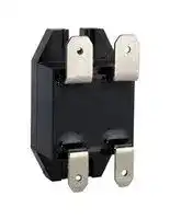
EL100D10-24N
Solid State Relay, SPST-NO, 10 A, 100 VDC, Panel Mount, Quick Connect, Right Angle
⚠️ Reference pricing provided. In case of supply shortages, we will connect you with our trusted procurement partners to ensure your project's continuity.
- Manufacturer: SENSATA/CRYDOM
- Product type:
- SVHC: No SVHC (21-Jan-2025)
- Load Current: 10A
- Product Range: EL Series
- Relay Mounting: Panel Mount
- Switching Mode: -
- Relay Terminals: Quick Connect, Right Angle
- Control Voltage Max: 27VDC
- Control Voltage Min: 21VDC
- Contact Configuration: SPST-NO
- Operating Voltage Max: 100VDC
- Operating Voltage Min: 3VDC
| Delivery and price | |
|---|---|
| Units per pack | 10 |
| Price | 39.77 € |
| Current stock | 10+ |
| Lead time | 20 days |
Datasheet

## **EL SERIES | DC OUTPUT** PANEL MOUNT SOLID STATE RELAYS

Sensata | Crydom EL Series DC output solid state relays come in a compact, 21 x 35 mm housing and offer ratings up to 20 Amps. These compact SSRs come with a pre-installed thermal pad, and are C-UL-US and TUV certified and CE compliant. The EL Series mechanical design includes quick connect terminals and an innovative 90° bent terminals option ideal for applications with limited vertical space.

## Features

- Ratings of 5A, 10A and 20A @ 3-100 VDC

- UL Recognized, TUV, CE and RoHS Compliant

- 5, 12 and 24 VDC control input options

- Mosfet Output

- Thermal Pad Included

- Plastic housing with min. 250 CTI rating (PLC2) for demanding applications

## Applications

- Battery Management Systems

- Backup Power Supplies

- Valves

- Vending Equipment

- Lighting control

- Medical Equipment

## **PRODUCT SELECTION**

|**Control Voltage**|**5A**|**10A**|**20A**|
|---|---|---|---|
|**4-8 VDC**|EL100D5-05|EL100D10-05|EL100D20-05|
|**10-14 VDC**|EL100D5-12|EL100D10-12|EL100D20-12|
|**21-27 VDC**|EL100D5-24|EL100D10-24|EL100D20-24|


Page 1

Copyright © 2021 Sensata Technologies, Inc.

www.sensata.com

## **SPECIFICATIONS**

## Output[(1)(3)]

**==> picture [541 x 177] intentionally omitted <==**

**----- Start of picture text -----**<br>
Description 5A 10A 20A<br>Operating Voltage [VDC] 3-100 3-100 3-100<br>Maximum Load Current [Adc] [ (2)] 5 10 20<br>Minimum Load Current [mAdc] 20 20 2.5<br>Maximum Surge Current Non-Repetitive<br>80 100 100<br>(10ms) [A]<br>Maximum Off-State Leakage Current @<br>100 100 100<br>Rated Voltage [µAdc]<br>Maximum On-State Resistance @ Rated<br>0.02 0.02 0.013<br>Current (Rds-on) [Ohm]<br>Maximum On-State Voltage Drop @ Rated<br>0.12 0.25 0.27<br>Current [VDC]<br>**----- End of picture text -----**<br>


## Input[(1)]

**==> picture [541 x 145] intentionally omitted <==**

**----- Start of picture text -----**<br>
Description EL100Dxx-05 EL100Dxx-12 EL100Dxx-24<br>Control Voltage Range 4-8 VDC 10-14 VDC 21-27 VDC<br>Minimum Turn-On Voltage 4 VDC 10 VDC 21 VDC<br>Must Turn-Off Voltage 1 VDC 1 VDC 1 VDC<br>Minimum Input Current 12 mA  10 mA 9 mA<br>Maximum Input Current 27 mA 15.5 mA 14 mA<br>Nominal Input Impedance [Ohms] 300 940 2k<br>Maximum Turn-On Time [msec] 1 1 1<br>Maximum Turn-Off Time [µsec]  300 300 300<br>**----- End of picture text -----**<br>


## General[(1)]

**==> picture [541 x 145] intentionally omitted <==**

**----- Start of picture text -----**<br>
Description Parameters<br>Dielectric Strength, Input to Output 2500 Vrms<br>Dielectric Strength, Output to Baseplate 2500 Vrms<br>Ambient Operating Temperature Range -30 to 80°C<br>Ambient Storage Temperature Range -30 to 125°C<br>Weight (typical) 0.5 oz (14.4 g)<br>Terminals 3/16”x 0.032” input, 1/4”x 0.032” output QC<br>SSR Mounting Screw Torque Range 9.0-10.0 lb-in (1.0-1.13 Nm)<br>Humidity per IEC60068-2-78 95% non-condensing<br>**----- End of picture text -----**<br>


Page 2

Copyright © 2021 Sensata Technologies, Inc.

www.sensata.com

## **MECHANICAL SPECIFICATIONS**

Tolerances: ±0.02 in / 0.5 mm All dimensions are in: inches [millimeters]

## **EQUIVALENT CIRCUIT BLOCK DIAGRAM / WIRING DIAGRAMS**

Page 3

Copyright © 2021 Sensata Technologies, Inc.

www.sensata.com

## **THERMAL DERATE INFORMATION**

**==> picture [252 x 311] intentionally omitted <==**

**----- Start of picture text -----**<br>
EL100D5-xx<br>5<br>4<br>3 6ºC/W<br>2<br>1<br>0<br>20 30 40 50 60 70 80<br>Ambient Temperature (ºC)<br>EL100D20-xx<br>4ºC/W<br>Ambient Temperature (ºC)<br>Load Current (Amps)<br>Load Current (Amps)<br>**----- End of picture text -----**<br>


## **EL100D10-xx**

**==> picture [239 x 126] intentionally omitted <==**

**----- Start of picture text -----**<br>
10<br>8<br>6 4ºC/W<br>6˚C/W<br>4<br>2<br>0<br>20 30 40 50 60 70 80<br>Ambient Temperature (ºC)<br>Load Current (Amps)<br>**----- End of picture text -----**<br>


## **MOUNTING INSTRUCTIONS**

Choose one of the two mounting options and follow the instructions

## **Mounting on Heat Sinks**

- Select adequate heat sink. (Please refer to thermal derating curves for the specific model)

- Be sure that thermal pad is pre-installed before installing over the heat sink.

- EL mounting slots have a diameter of 0.16 in (4.0 mm). Two screws are needed (not included) to mount the EL onto heat sink (See fig. 1). recommended screw size is 8-32 (UNC standard) or M4 (metric).

- Before applying full torque tighten down both screws until they contact the baseplate. Then, tighten them to 9.0-10.0 lb-in (1.0-1.13 Nm).

- For optimal thermal performance heat sink fins should be oriented vertically to promote natural convection airflow

**==> picture [99 x 168] intentionally omitted <==**

**----- Start of picture text -----**<br>
fig. 1 EL  mounted<br>on heat sink<br>**----- End of picture text -----**<br>


## **Mounting on Panels**

- Locate the panel section on which the EL will be mounted. Panel mount surface must provide adequate heat sinking capability, uncoated, clean, flat (0.004 in/in recommended) and preferably aluminum.

- Be sure that thermal pad is pre-installed before install over the heatsink.

- EL mounting slots have a diameter of 0.16 in (4.0 mm). Two screws are needed (not included) to mount the EL onto panel. Choose screw length considering the mounting surface hole depth and that the SSR flange thickness is 0.125 in (3.2 mm).

- Before applying full torque tighten down both screws until they contact the baseplate. Then, tighten them to 10 lb-in (1.13 Nm).

## **Transient Protection**

- An inductive load will produce harmful transient voltage when it is turned off. The more perfect the switch, the larger the transient voltages. The MOSFET output is so nearly ideal switch that the transient voltages produced by seemingly “non-inductive” loads can cause damage if not suppressed. Diodes should be fast recovery type with PIV rated greater than supply voltage.[(3)]

Page 4

Copyright © 2021 Sensata Technologies, Inc.

www.sensata.com

## **GENERAL NOTES**

(1) All parameters at 25°C unless otherwise specified.

(2) When mounted to the proper size heat sink (see derating curves)

(3) Inductive loads should be diode suppressed to prevent damage to the relay

**ORDERING OPTIONS** Example : EL100D10-05N © Wi **EL 100D 10 - 05 N** ~~— oH LI~~ **Series** _l **EL Output Voltage** ee **100D:** 3-100 VDC **Rated Load Current** — **5:** 5 Amps **10:** 10 Amps **20:** 20 Amps **Control Voltage 05:** 4-8 VDC **12:** 10-14 VDC **24:** 21-27 VDC **Termination** Required for valid part number **Blank:** Standard Quick Connect For options only and not required for valid part number e **N:** 90º bent Quick Connect  (10 and 20 Amps models only) ~~s~~

## **AGENCY APPROVALS & CERTIFICATIONS**

**==> picture [145 x 13] intentionally omitted <==**

**----- Start of picture text -----**<br>
E116950<br>(5 and 10 Amps only) (5 and 10 Amps only)<br>**----- End of picture text -----**<br>


## **Certification in accordance with:**

United States Standard for Industrial Control Equipment - UL 508 and Canadian Standard Association for Industrial Control Equipment – C22.2 No. 14.

TUV SUD according to IEC 60335-1.

Vibration and Shock Resistance: IEC 61373 : Category 1, Class B.

Page 5

Copyright © 2021 Sensata Technologies, Inc.

www.sensata.com

## **WARNINGS**

RISK OF MATERIAL DAMAGE AND HOT ENCLOSURE

- The product’s side panels may be hot, allow the product to cool before touching

- Follow proper mounting instructions including torque values

- Do not allow liquids or foreign objects to enter this product

**Failure to follow these instructions can result in serious injury, or equipment damage.**

HAZARD OF ELECTRIC SHOCK, EXPLOSION OR ARC FLASH

- Disconnect all power before installing or working with this equipment

- Verify all connections and replace all covers before turning on power **Failure to follow these instructions will result in death or serious injury.**

Sensata Technologies, Inc. (“Sensata”) data sheets are solely intended to assist designers (“Buyers”) who are developing systems that incorporate Sensata products (also referred to herein as “components”). Buyer understands and agrees that Buyer remains responsible for using its independent analysis, valuation, and judgment in designing Buyer’s systems and products. Sensata data sheets have been created using standard laboratory conditions and engineering practices. Sensata has not conducted any testing other than that specifically described in the published documentation for a particular data sheet. Sensata may make corrections, enhancements, improvements, and other changes to its data sheets or components without notice. Buyers are authorized to use Sensata data sheets with the Sensata component(s) identified in each particular data sheet. HOWEVER, NO OTHER LICENSE, EXPRESS OR IMPLIED, BY ESTOPPEL OTHERWISE TO ANY OTHER SENSATA INTELLECTUAL PROPERTY RIGHT, AND NO LICENSE TO ANY THIRD PARTY TECHNOLOGY OR INTELLECTUAL PROPERTY RIGHT, IS GRANTED HEREIN. SENSATA DATA SHEETS ARE PROVIDED “AS IS”. SENSATA MAKES NO WARRANTIES OR REPRESENTATIONS WITH REGARD TO THE DATA SHEETS OR USE OF THE DATA SHEETS, EXPRESS, IMPLIED, OR STATUTORY, INCLUDING ACCURACY OR COMPLETENESS. SENSATA DISCLAIMS ANY WARRANTY OF TITLE AND ANY IMPLIED WARRANTIES OF MERCHANTABILITY, FITNESS FOR A PARTICULAR PURPOSE, QUIET ENJOYMENT, QUIET POSSESSION, AND NON-INFRINGEMENT OF ANY THIRD PARTY INTELLECTUAL PROPERTY RIGHTS WITH REGARD TO SENSATA DATA SHEETS OR USE THEREOF.

All products are sold subject to Sensata’s terms and conditions of sale supplied at www.sensata.com SENSATA ASSUMES NO LIABILITY FOR APPLICATIONS ASSISTANCE OR THE DESIGN OF BUYERS’ PRODUCTS. BUYER ACKNOWLEDGES AND AGREES THAT IT IS SOLELY RESPONSIBLE FOR COMPLIANCE WITH ALL LEGAL, REGULATORY, AND SAFETY-ELATED REQUIREMENTS CONCERNING ITS PRODUCTS, AND ANY USE OF SENSATA COMPONENTS IN ITS APPLICATIONS, NOTWITHSTANDING ANY APPLICATIONS-RELATED INFORMATION OR SUPPORT THAT MAY BE PROVIDED BY SENSATA.

## **CONTACT US**

## **Americas**

+1 (877) 502 5500 – Option 2 sales.crydom@sensata.com

**Europe, Middle East & Africa** +44 (1202) 416170 ssr-info.eu@sensata.com **Asia Pacific** sales.isasia@list.sensata.com China +86 (21) 2306 1500 Japan +81 (45) 277 7117 Korea +82 (31) 601 2004 India +91 (80) 67920890 Rest of Asia +886 (2) 27602006 ext 2808

Mailing Address: Sensata Technologies, Inc., 529 Pleasant Street, Attleboro, MA 02703, USA

Page 6

www.sensata.com

Rev:05/28/2021 ECN 21137 FDE-07-01 Rev. B

Copyright © 2021 Sensata Technologies, Inc.
Updated at June 5, 2026
About Novapart
Novapart is a B2B electronic component broker specialising in stock shortages and cost reduction. We source hard-to-find parts and identify compliant alternatives across a catalogue of 410,000+ components from 500+ manufacturers.
Learn more →Stock Shortage Specialist
When a component is unavailable, discontinued or has an unacceptable lead time, we tap into our network of vetted European and Asian distributors to source what you need — without compromising on quality or traceability.
Request a quote →Compliant Alternatives
We identify pin-to-pin, electrically equivalent substitutes that meet the same certifications (RoHS, AEC-Q100, REACH) as your original specification — validated against datasheets, not just part numbers. Often at a lower cost.
BOM Analysis service →