
Image not available
Illustrative purposes only

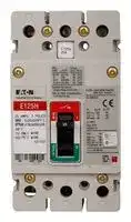
EGH3060FFG
CIRCUIT BREAKER, 3 POLE, 60A
⚠️ Reference pricing provided. In case of supply shortages, we will connect you with our trusted procurement partners to ensure your project's continuity.
- Manufacturer: EATON CUTLER HAMMER
- Product type: Thermal Magnetic Circuit Breakers
- Product Ra; CIRCUIT BREAKER, 3 POLE, 60A; Product Range:EG Series; Current Rating:60A; No. of Poles:3 Pole; Voltage Rating VDC:-; Voltage Rating VAC:415; Available until stocks are exhausted
- No. of Poles: 3 Pole
- Product Range: G Series
- Current Rating: 60A
- Voltage Rating VAC: 415V
- Voltage Rating VDC: -
- Circuit Breaker Mounting: DIN Rail, Panel
| Delivery and price | |
|---|---|
| Units per pack | 5 |
| Price | 693.5 € |
| Current stock | 10+ |
| Lead time | 30 days |
Datasheet

## Circuit Protection

## **Circuit Breakers**

**Fuse Blocks and Fuse Holders**

**Rotary Disconnect Switches**

|**1.1**|**Circuit Breakers**<br>Product Overview  . . . . . . . . . . . . . . . . . . . . . . . . . . . . . . . . . . . . . . . .|**V9-T1-2**|**1**|
|---|---|---|---|
||Series G Molded Case Circuit Breakers . . . . . . . . . . . . . . . . . . . . . . . .|**V9-T1-5**|**1**|
||Series G Motor Circuit Protectors. . . . . . . . . . . . . . . . . . . . . . . . . . . . .|**V9-T1-8**||
||Series G Motor Protector Breakers  . . . . . . . . . . . . . . . . . . . . . . . . . . .|**V9-T1-10**|**1**|
||Universal Molded Case Circuit Breakers . . . . . . . . . . . . . . . . . . . . . . .<br>QUICKLAG Type QC Miniature Circuit Breakers—|**V9-T1-13**|**1**|
||Cable-In/Cable-Out Type QC  . . . . . . . . . . . . . . . . . . . . . . . . . . . . . . .|**V9-T1-19**|**1**|
||FAZ-NA UL 489 Circuit Breakers  . . . . . . . . . . . . . . . . . . . . . . . . . . . . .|**V9-T1-25**||
||FAZ UL 1077 Circuit Breakers  . . . . . . . . . . . . . . . . . . . . . . . . . . . . . . .|**V9-T1-28**|**1**|
||Series NRX Low Voltage Power Breakers  . . . . . . . . . . . . . . . . . . . . . .<br>Magnum Low Voltage Power Breakers . . . . . . . . . . . . . . . . . . . . . . . .|**V9-T1-33**<br>**V9-T1-36**|**1**|
|**1.2**|**Fuse Blocks and Fuse Holders**||**1**|
||Product Overview  . . . . . . . . . . . . . . . . . . . . . . . . . . . . . . . . . . . . . . . .<br>C350 Series . . . . . . . . . . . . . . . . . . . . . . . . . . . . . . . . . . . . . . . . . . . . .|**V9-T1-44**<br>**V9-T1-45**|**1**|
|**1.3**|**Rotary Disconnect Switches**||**1**|
||Open Rotary Disconnects  . . . . . . . . . . . . . . . . . . . . . . . . . . . . . . . . . .<br>Enclosed Rotary Disconnects  . . . . . . . . . . . . . . . . . . . . . . . . . . . . . . .|**V9-T1-46**<br>**V9-T1-62**|**1**|


For our complete product offering, see Volume 4—Circuit Protection, CA08100005E and Volume 5—Motor Control and Protection, CA08100006E.

**Volume 9—OEM—Original Equipment Manufacturer** CA08100011E—February 2014 www.eaton.com

**V9-T1-1**

Circuit Protection

1.1

Circuit Breakers

**1**

## **Product Overview**

## **Circuit Breaker Selection Guide**

**Series G Description Molded Case Circuit Breaker Page V9-T1-5 General Applications**

Line protection—molded case switch, motor circuit protection (combination tested with Eaton starters and contactors) thermal-magnetic and electronic trip units.

**QUICKLAG**[®] **Type QC Miniature Circuit Breakers**

**Universal Molded Case Circuit Breakers**

**Page V9-T1-13 Page V9-T1-19** Line protection—feeder and branch thermalUsed to provide branch circuit protection in magnetic trip unit. cable-in/out panel or DIN rail mount applications.

||and contactors) thermal-magnetic and electronic<br>trip units.|and contactors) thermal-magnetic and electronic|||applications.|
|---|---|---|---|---|---|
|**Technical Data**||||||
|Maximum current rating|2500A||600A||100A|
|Maximum voltage—AC<br>Maximum voltage—DC|690 Vac<br>250 Vdc||480 Vac<br>250 Vdc||240 Vac<br>80 Vdc|
|Poles|1, 2, 3, 4||1, 2, 3||QC = 1, 2, 3, 4<br>QCD = 1, 2, 3|
||||||QCR/QCF = 1, 2, 3|
|Max. interrupting capacities|Three-pole at 240V|Three-pole at 480V|Three-pole at 240V|Three-pole at 480V|65 kA at 240 Vac|
|See individual catalogs for<br>limitations and back-up<br>protection requirements.|E = 200 kA<br>J = 200 kA<br>L = 200 kA|E = 100 kA<br>J = 200 kA<br>L = 200 kA|G = 25 kA (480/277)<br>F = 25 kA<br>J = 35 kA<br>K = 35 kA|GI = 14 kA (480/277)<br>GD = 22 kA<br>F = 14 kA<br>J = 20 kA|5 kA at 80 Vdc|
||||L = 35 kA|K = 20 kA<br>L = 20 kA||
|**Approvals**||||||
||UL®489|CSA®|UL 489CE|CE|UL 489|
||IEC 60947-2<br>CE|KEMA-KEUR<br>CCC|IEC 60947-2|CSA|CSA 22.2|
|**Environmental Data**||||||
|Humidity|Non-condensing 100% relative humidity||Non-condensing 100% relative humidity||—|
|Shock|—||—||—|
|Vibration|—||—||—|
|Operating temperature|–20° to 70°C (–4° to 158°F) derating applies|–20° to 70°C (–4° to 158°F) derating applies|–20° to 70°C (–4° to 158°F) derating applies|–20° to 70°C (–4° to 158°F) derating applies|40°C (104°F)|
|Dielectric strength|Below 250A 6 kV<br>Above 250A 8 kV||Below 250A 6 kV<br>Above 250A 8 kV||1960 Vac (acc. to UL 489)|
|Insulation resistance|750 Vac||750 Vac||—|
|Endurance/life|250A: EG, JG = 8,000 operations||250A: Gi = 10,000 operations||>10,000 operations|
||630A: LG = 6,000 operations||Fi = 8,000 operations|||
||||400A: Ji, Ki, Li = 6,000 operations|||
|Approximate weight|E Three-pole—2.88 lbs (1.04 kg)||G Three-pole—2.10 lbs (0.95 kg)||QC<br>Single-pole—0.36 lbs (162.8 g)|
||J Three-pole—5.06 lbs (2.30 kg)<br>L Three-pole—12.36 lbs (5.61 kg)||F Three-pole—4.5 lbs (2.0 kg)<br>J Three-pole—12.50 lbs (5.7 kg)||Two-pole—0.61 lbs (274.9 g)<br>Three-pole—1.14 lbs (518.3 g)|
||||K Three-pole—11.50 lbs (5.2 kg)||QCD Single-pole—0.43 lbs (195.3 g)<br>Two-pole—0.89 lbs (401.9 g)|
||||||Three-pole—1.34 lbs (605.6 g)|
||||||QCR Single-pole—0.22 lbs (97.9 g)<br>Two-pole—0.48 lbs (215.8 g)|
||||||Three-pole—0.70 lbs (315.6 g)<br>QCF Single-pole—0.24 lbs (109.9 g)|
||||||Two-pole—0.50 lbs (225.2 g)|
||||||Three-pole—0.74 lbs (335.1 g)|
|Mounting configuration|Backpan, plug-in adapter, DIN rail (E)||Backpan, DIN rail (G)||Panel mount, front mount, 35 mm DIN rail|
||||||mountable|


For our complete product offering, see Volume 4—Circuit Protection, CA08100005E.

**Volume 9—OEM—Original Equipment Manufacturer** CA08100011E—February 2014 www.eaton.com

**V9-T1-2**

Circuit Protection Circuit Breakers

1.1

**1**

## **Circuit Breaker Selection Guide, continued**

|||**FAZ UL 1077**|
|---|---|---|
||**FAZ-NA UL 489**|**Miniature Circuit Breakers—**|
|**Description**|**Miniature Circuit Breakers**|**Supplementary Protectors**|
||**Page V9-T1-25**|**Page V9-T1-28**|
|**General Applications**|||
||Used to provide branch circuit protection in cable-|Used to provide overcurrent protection where|
||in/out DIN rail mount applications.|branch protection (for example UL 489 MCCB) is|
|||already provided or not required. Replacement for|
|||fuses used as supplementary protectors.|
|**Technical Data**|||
|Maximum current rating|40A|63A|
|Maximum voltage—AC|480/277 Vac (240/415 Vac IEC)|480/277 Vac|
|Maximum voltage—DC|48 Vdc|65 Vac Single-pole|
|||130 Vac Two-pole|
|Poles|1, 2, 3|1, 2, 3|
|Max. interrupting capacities|10 kA UL/CSA;|IEC<br>240/415V 10 kA|
|See individual catalogs for limitations<br>and back-up protection requirements.|15 kA IEC/EN 60947-2|UL/CSA 120V 10 kA<br>240V 10 kA<br>277V 6 kA|
|||480V 6 kA|
|**Approvals**|||
||UL 489|UL 1077|
||CE; IEC/EN 60947-2|CE; IEC/EN 60947-2; IEC/EN 60898|
||CSA 22.2|CSA 22.2 235|
|**Environmental Data**|||
|Humidity|Acc. IEC 60068-2 (25° to 55°C/|—|
||77° to 131°F, 90–95% RH)||
|Shock|Acc. IEC 60068-2-27|—|
||(40g half sine wave for 10 ms—3 axes)||
||(15g half sine wave for 20 ms—3 axes)||
|Vibration|Acc. to IEC 60068-2-6|—|
||5–100 Hz/1.0 mm/0.7g (3 axes)||
|Operating temperature|30°C (86°F)|—|
|Dielectric strength|1960 Vac (acc. to UL 489)|—|
|Insulation resistance|100M ohms at 500 Vdc|—|
|Endurance/life|>20,000 operations|—|
|Approximate weight|Single-pole—0.27 lbs (121.0g)|Single-pole—0.26 lbs (120.0g)|
||Two-pole—0.53 lbs (242.0g)|Two-pole—0.54 lbs (244.9g)|
||Three-pole—0.80 lbs (363.0g)|Three-pole—0.83 lbs (376.5g)|
|Mounting contribution|35 mm DIN rail mountable|35 mm DIN rail mountable|


For our complete product offering, see Volume 4—Circuit Protection, CA08100005E.

**Volume 9—OEM—Original Equipment Manufacturer** CA08100011E—February 2014 www.eaton.com

**V9-T1-3**

Circuit Protection

1.1

Circuit Breakers

**1**

## **Circuit Breaker Selection Guide, continued**

||a -||
|---|---|---|
||**Series NRX**|**Magnum**|
|**Description**|**Low Voltage Power Breakers**<br>**Page V9-T1-33**|**Low Voltage Power Breakers**<br>**Page V9-T1-36**|
|**General Applications**|||
||Solution for where space is at a premium or when|Enables comprehensive solutions to meet and|
||equipment dimensions are critical when upgrading<br>or retrofitting current systems. Offering the power|exceed the unique and wide-ranging requirements<br>of today’s global power distribution systems.|
||and performance of a power breaker in the compact|Designed and engineered for ultimate custom|
||size of a molded case breaker. With its reduced<br>weight and compact dimensions, you can mount|configuration and application flexibility in metal<br>enclosed switchgear and power distribution|
||two times as many feeder breakers and reduce the<br>overall enclosure density up to 50%.|enclosures.|
|**Technical Data**|||
|Maximum current rating|630–1600A|800–6300A|
|Maximum voltage—AC<br>Maximum voltage—DC|220–690 Vac<br>—|Up to 690 Vac<br>—|
|Poles|3, 4|3, 4|
|Max. interrupting capacities|65 kAIC at 480 Vac|200 kA at 480 Vac|
|See individual catalogs for limitations<br>and back-up protection requirements.<br>**Approvals**|Max. withstand capacities 42 kAIC|Max. withstand capacities<br>100 kAIC<br>CL fuseless 200 kA at 635 Vac with integral limiters|
||UL 1006 Component<br>UL 489 Component|UL 1066<br>IEC 60947-2|
||IEC 60947-2|KEMA|
|**Environmental Data**|||
|Humidity<br>Shock|—<br>—|—<br>—|
|Vibration|—|—|
|Operating temperature<br>Dielectric strength|–25° to 70°C<br>—|–25° to 70°C<br>—|
|Insulation resistance|—|—|
|Endurance/life|10,000 electrical operations|—|
||20,000 mechanical operations||
|Approximate weight|Three-pole breaker + cassette—85 lbs (39 kg)|—|
||Three-pole breaker—53 lbs (24 kg)<br>Four-pole breaker + cassette—104 lbs (47 kg)||
||Four-pole breaker—67 lbs (30 kg)||
|Mounting configuration|Rear-connected, front-connected,|Fixed or drawout with cassette rear-connected, front-|
||surface mounting, mounting bracket,|connected|
||fixed, drawout breaker with cassette||


For our complete product offering, see Volume 4—Circuit Protection, CA08100005E.

**Volume 9—OEM—Original Equipment Manufacturer** CA08100011E—February 2014 www.eaton.com

**V9-T1-4**

Circuit Protection

1.1

Circuit Breakers

## **Series G Molded Case Circuit Breakers**

## **Features**

- Field-fit accessories

**1**

- Common accessories through 630A

- Space-saving footprint

- High-performance current limiting designs up to 200 kAIC at 480V

- Global ready: UL, CSA, CE, IEC, KEMA-KEUR listings

- Complete breaker includes frame, trip unit, standard terminals and mounting hardware

## **Catalog Number Selection**

**Series G**[®] **Molded Case Circuit Breakers**

**EG Frame**

**==> picture [106 x 11] intentionally omitted <==**

**----- Start of picture text -----**<br>
E G H 3 015 FF G<br>**----- End of picture text -----**<br>


**==> picture [452 x 172] intentionally omitted <==**

**----- Start of picture text -----**<br>
Frame Terminations/Hardware<br>E Terminals Mounting Hardware<br>A mperes M  = Metric end caps Metric<br>Standard/Application Number of Poles 016 [2] E = Imperial end caps Imperial<br>G  = IEC/CE/UL/CSA 12  = One = Two 015020 GB = Line/load standard= Bolt-on Metric—<br>3  = Three 025<br>Performance 4  = Four—Neutral 0% Protected 030 Trip Unit<br>600Y/347 480 415 240 7  = Four—Neutral 100% Protected 032 [2]<br>FF  = Fixed fixed<br>BE —18 1825 2518 3525 035040045 AF  = Adjustable thermal fixed magnetic<br>S 22 35 40 85 050 KS   = Molded case switch<br>H 25 65 70 100 060<br>C 35 100 100 200 063 [2]<br>K Molded case switch  [1] 070<br>080<br>090<br>100<br>110<br>125<br>**----- End of picture text -----**<br>


## _**Notes**_

- 1 Available only as 125 and 160A sizes.

> 2 Is not UL rated.

**Volume 9—OEM—Original Equipment Manufacturer** CA08100011E—February 2014 www.eaton.com

**V9-T1-5**

Circuit Protection

1.1

Circuit Breakers

**JG Frame 1**

**==> picture [452 x 215] intentionally omitted <==**

**----- Start of picture text -----**<br>
J G S 3 250 FA G C<br>Frame Rating<br>J Blank  = 80% rated<br>C  = 100% rated<br>Standard/Application Amperes<br>G  = IEC/CE/UL/CSA Number of Poles 050 Terminations/Hardware<br>2  = Two 070 Terminals Mounting Hardware<br>3  = Three 080<br>E 18 600 Performance 25 480 25 415 65 240 489  = Four—Neutral 0% protected = Four—Neutral 0–60% protected = Four—Neutral 100% protected 090100125 MEG  = Metric end caps= Imperial end caps= Line/load standard MetricImperialMetric<br>150<br>S 18 35 40 85<br>160 Trip Unit<br>H 25 65 70 100 175 AA   = Adjustable thermal<br>C 35 100 100 200 200 Adjustable magnetic<br>U 50 150 150 200 225 FA  = Fixed thermal<br>X 50 200 200 200 250 Adjustable magnetic<br>KS   = Molded case switch<br>K Molded case switch<br>33   = 310+ electronic LS<br>32   = 310+ electronic LSI<br>35   = 310+ electronic LSG<br>36   = 310+ electronic LSIG<br>NN  = Frame only (no trip)<br>**----- End of picture text -----**<br>


## **LG Frame**

**==> picture [452 x 239] intentionally omitted <==**

**----- Start of picture text -----**<br>
L G S 3 600 FA G C<br>Frame Rating<br>L Blank  = 80% rated<br>C  = 100% rated<br>Standard/Application A mperes<br>G  = IEC/CE/UL/CSA Number of Poles 250 Terminations/Hardware<br>3  = Three 300 Terminals Mounting Hardware<br>Performance 4  = Four—Neutral 0% protected 350 M  = Metric end caps Metric<br>600 480 415 240 67  = Four—Neutral 60% protected = Four—Neutral 100% protected 400500 EG = Imperial end caps= Line/load standard ImperialMetric<br>E 18 35 35 65 8  = Four—Neutral 0–60% protected 600 W = Without terminals —<br>S 25 50 50 85 9  = Four—Neutral 0–100 protected 630<br>H 35 65 70 100 Trip Unit  [1]<br>C 50 100 100 200 AA   = Adjustable thermal<br>U 65 150 150 200 Adjustable magnetic<br>X 65 200 200 200 FA  = Fixed thermal<br>K Molded case switch  Adjustable magnetic<br>KS   = Molded case switch<br>33   = 310+ electronic LS<br>32   = 310+ electronic LSI<br>35   = 310+ electronic LSG<br>36   = 310+ electronic LSIG<br>38   = 310+ electronic ALSI<br>39   = 310+ electronic ALSIG<br>NN  = Frame only (no trip)<br>**----- End of picture text -----**<br>


_**Note**_

> 1 A = Arc reduction, L = Long, S = Short, I = Instantaneous, G = Ground.

**Volume 9—OEM—Original Equipment Manufacturer** CA08100011E—February 2014 www.eaton.com

**V9-T1-6**

Circuit Protection

1.1

Circuit Breakers

**1**

## **Product Selection**

## **Series G Molded Case Circuit Breakers**

Approximate Dimensions are in Inches

## **EG Frame**

|**EG Frame**||
|---|---|
|**Maximum**<br>**Continuous**<br>**Amperes at 40°C**1<br>**Three-Pole 3.00 W x 5.50 H x 2.99 D**<br>**Fixed Thermal**<br>**Fixed Magnetic**<br>**IC Rating: 25 kAIC at 415 and 480 Vac**<br>15<br>**EGE3015FFG**<br>20<br>**EGE3020FFG**<br>25<br>**EGE3025FFG**<br>30<br>**EGE3030FFG**<br>35<br>**EGE3035FFG**<br>40<br>**EGE3040FFG**<br>45<br>**EGE3045FFG**<br>50<br>**EGE3050FFG**<br>60<br>**EGE3060FFG**<br>70<br>**EGE3070FFG**<br>80<br>**EGE3080FFG**<br>90<br>**EGE3090FFG**<br>100<br>**EGE3100FFG**<br>125<br>**EGE3125FFG**|**Maximum**<br>**Continuous**<br>**Amperes at 40°C**<br>**Three-Pole 3.00 W x 5.50 H x 2.99 D**<br>**Fixed Thermal**<br>**Fixed Magnetic**|
||**IC Rating: 70 kAIC at 415 Vac, 65 kAIC at 480 Vac**|
||15<br>**EGH3015FFG**|
||20<br>**EGH3020FFG**|
||25<br>**EGH3025FFG**|
||30<br>**EGH3030FFG**|
||35<br>**EGH3035FFG**|
||40<br>**EGH3040FFG**|
||45<br>**EGH3045FFG**|
||50<br>**EGH3050FFG**|
||60<br>**EGH3060FFG**|
||70<br>**EGH3070FFG**|
||80<br>**EGH3080FFG**|
||90<br>**EGH3090FFG**|
||100<br>**EGH3100FFG**|
||125<br>**EGH3125FFG**|


## **JG Frame**

|**JG Frame**||
|---|---|
|**Maximum**<br>**Continuous**<br>**Amperes**<br>**Three-Pole 4.13 W x 7.00 H x 3.57 D**<br>**Magnetic**<br>**Range**<br>**Fixed Thermal**<br>**Adjustable Magnetic**<br>**IC Rating: 25 kAIC at 415 and 480 Vac**<br>70<br>350–700<br>**JGE3070FAG**<br>90<br>450–900<br>**JGE3090FAG**<br>100<br>500–1000<br>**JGE3100FAG**<br>125<br>625–1250<br>**JGE3125FAG**<br>150<br>750–1550<br>**JGE3150FAG**<br>175<br>875–1750<br>**JGE3175FAG**<br>200<br>1000–2000<br>**JGE3200FAG**<br>225<br>1125–2250<br>**JGE3225FAG**<br>250<br>1250–2500<br>**JGE3250FAG**|**Maximum**<br>**Continuous**<br>**Amperes**<br>**Three-Pole 4.13 W x 7.00 H x 3.57 D**<br>**Magnetic**<br>**Range**<br>**Fixed Thermal**<br>**Adjustable Magnetic**|
||**IC Rating: 70 kAIC at 415 Vac, 65 kAIC at 480 Vac**|
||70<br>350–700<br>**JGH3070FAG**|
||90<br>450–900<br>**JGH3090FAG**|
||100<br>500–1000<br>**JGH3100FAG**|
||125<br>625–1250<br>**JGH3125FAG**|
||150<br>750–1550<br>**JGH3150FAG**|
||175<br>875–1750<br>**JGH3175FAG**|
||200<br>1000–2000<br>**JGH3200FAG**|
||225<br>1125–2250<br>**JGH3225FAG**|
||250<br>1250–2500<br>**JGH3250FAG**|


## **LG Frame**

|**LG Frame**||
|---|---|
|**Ampere**<br>**Rating**<br>**Three-Pole 5.48 W x 10.13 H x 4.09 D**<br>**Fixed Thermal**<br>**Adjustable Magnetic**<br>**IC Rating: 35 kAIC at 415 and 480 Vac**<br>250<br>**LGE3250FAG**<br>300<br>**LGE3300FAG**<br>350<br>**LGE3350FAG**<br>400<br>**LGE3400FAG**<br>500<br>**LGE3500FAG**<br>600<br>**LGE3600FAG**|**Ampere**<br>**Rating**<br>**Three-Pole 3.00 W x 5.50 H x 2.99 D**<br>**Fixed Thermal**<br>**Adjustable Magnetic**|
||**IC Rating: 70 kAIC at 415 Vac, 65 kAIC at 480 Vac**|
||250<br>**LGH3250FAG**|
||300<br>**LGH3300FAG**|
||350<br>**LGH3350FAG**|
||400<br>**LGH3400FAG**|
||500<br>**LGH3500FAG**|
||600<br>**LGH3600FAG**|


## _**Note**_

> 1 16, 32, 63A are not UL listed ratings.

**Volume 9—OEM—Original Equipment Manufacturer** CA08100011E—February 2014 www.eaton.com

**V9-T1-7**

Circuit Protection

1.1

Circuit Breakers

**1 Series G Motor Circuit Protector**

## **Features**

- Instantaneous only protector

- Designed for use in combination with motor starters

- Adjustable to motor FLA

- UL recognized component, File E7819 motor circuit protectors

## **Product Selection**

## **Series G Motor Circuit Protectors**

## **EG Frame—480 Vac, 600Y/347 Vac Maximum**

|**Continuous**<br>**Amperes**|**Cam**<br>**Setting**|**Motor Full Load**<br>**Current Amperes**1|**MCP Trip**<br>**Setting**2|**MCP**<br>**Catalog Number**|**Continuous**<br>**Amperes**|**Cam**<br>**Setting**|**Motor Full Load**<br>**Current Amperes**1|**MCP Trip**<br>**Setting**2|**MCP**<br>**Catalog Number**|
|---|---|---|---|---|---|---|---|---|---|
|3|A|0.69–0.91|9|**HMCPE003A0C**|50|A|11.5–15.2|150|**HMCPE050K2C**|
||B|1.1–1.3|15|||B|19.2–22.9|250||
||C<br>D|1.6–1.7<br>2.0–2.2|21<br>27|||C<br>D|26.9–30.6<br>34.6–38.3|350<br>450||
||E|2.3–2.5|30|||E|38.4–42.1|500||
||F|2.6–2.8|33|||F|42.2–43.5|550||
|7|A|1.5–2.0|21|**HMCPE007C0C**|70|A|16.1–30.6|210|**HMCPE070M2C**|
||B|2.6–3.1|35|||B|26.9–32.2|350||
||C|3.7–3.9|49|||C|37.6–42.9|490||
||D|4.8–5.2|63|||D|48.4–53.7|630||
||E|5.3–5.7|70|||E|53.8–59.1|700||
|15|F<br>A|5.8–6.1<br>3.4–4.5|77<br>45|**HMCPE015E0C**|100|F<br>A|59.2–60.9<br>23.0–30.6|770<br>300|**HMCPE100R3C**|
||B|5.7–6.8|75|||B|38.4–46.0|500||
||C|8.0–9.1|105|||C|53.8–61.4|700||
||D|10.4–11.4|135|||D|69.2–76.8|900||
||E|11.5–12.6|150|||E|76.9–84.5|1000||
||F|12.7–13.0|165|||F|84.6–87.0|1100||
|30|A|3.9–9.1|90|**HMCPE030H1C**|100|A|38.4–46.0|500|**HMCPE100T3C**|
||B|11.5–13.7|150|||B|57.6–65.2|750||
||C<br>D|16.1–18.3<br>20.7–22.9|210<br>270|||C<br>D|76.9–84.5<br>3|1000<br>1250||
||E|23.0–25.2|300|||E|3|1375||
||F|25.3–26.1|330|||F|3|1500||


## _**Notes**_

- 1 Motor FLA ranges are typical. The corresponding trip setting is at 13 times the minimum FLA value shown. Where a 13 times setting is required for an intermediate FLA value, alternate cam settings and/or MCP ratings should be used.

- 2 For DC applications, actual trip levels are approximately 40% higher than values shown.

- 3 Settings above 10 x In are for special applications, where the ampere rating of the disconnecting means cannot be less than 115% of the motor full load ampere rating.

**Volume 9—OEM—Original Equipment Manufacturer** CA08100011E—February 2014 www.eaton.com

**V9-T1-8**

Circuit Protection Circuit Breakers

1.1

**1**

**JG Frame—600 Vac Maximum, 250 Vdc Maximum**

|**Continuous**<br>**Amperes**|**MCP Trip Range**<br>**Amperes**<br>**MCP**<br>**Catalog Number**|
|---|---|
|250|500–1000<br>**HMCPJ250D5L**|
||625–1250<br>**HMCPJ250F5L**|
||750–1500<br>**HMCPJ250G5L**|
||875–1750<br>**HMCPJ250J5L**|
||1000–2000<br>**HMCPJ250K5L**|
||1125–2250<br>**HMCPJ250L5L**|
||1250–2500<br>**HMCPJ250W5L**|


**LG Frame—600 Vac Maximum, 250 Vdc Maximum**

|**Continuous**<br>**Amperes**|**MCP Trip Range**<br>**Amperes**<br>**MCP**<br>**Catalog Number**|
|---|---|
|600|1250–2500<br>**HMCPL600L6G**|
||1500–3000<br>**HMCPL600N6G**|
||1750–3500<br>**HMCPL600R6G**|
||2000–4000<br>**HMCPL600X6G**|
||2250–4500<br>**HMCPL600Y6G**|
||2500–5000<br>**HMCPL600P6G**|
||3000–6000<br>**HMCPL600M6G**|


**Volume 9—OEM—Original Equipment Manufacturer** CA08100011E—February 2014 www.eaton.com

**V9-T1-9**

Circuit Protection

1.1

Circuit Breakers

**1**

## **Series G Motor Protector Breakers**

## **Features**

- Eliminates need for separate overload relay

- Can be used with contactor to eliminate need for overload relay and still create manual motor control

- Meets requirement for motor branch protection, including:

- Disconnecting means

- Branch circuit short-circuit protection

- Overload protection

- UL 489 listed, IEC 60947-02 rated

- Phase unbalance, phase loss protection and high load alarm

- Optional pre-detection trip relay

## **Product Selection**

## **Series G Motor Protector Breakers**

For pre-trip alarm option, order Style Number 5721B31G02.

## **JG Frame Motor Protector Circuit Breakers, 250A Maximum Rated Current**

|**Continuous**<br>**Amperes**|**35 kAIC**<br>**Catalog Number**|**65 kAIC**<br>**Catalog Number**|
|---|---|---|
|50|**JGMPS050G**|**JGMPH050G**|
|100|**JGMPS100G**|**JGMPH100G**|
|160|**JGMPS160G**|**JGMPH160G**|
|250|**JGMPS250G**|**JGMPH250G**|


## **LG Frame Motor Protector Circuit Breakers, 630A Maximum Rated Current**

|**Continuous**|**50 kAIC**|**65 kAIC**|
|---|---|---|
|**Amperes**|**Catalog Number**|**Catalog Number**|
|250|**LGMPS250G**|**LGMPH250G**|
|400|**LGMPS400G**|**LGMPH400G**|
|600|**LGMPS600G**|**LGMPH600G**|
|6301|**LGMPS630G**|**LGMPH630G**|


_**Note**_

> 1 630A is not a UL listed rating. 600A is the maximum UL or CSA rating for LG breaker.

**Volume 9—OEM—Original Equipment Manufacturer** CA08100011E—February 2014 www.eaton.com

**V9-T1-10**

Circuit Protection

1.1

Circuit Breakers

**1**

## **Accessories**

## **Field Fit Kit Catalog Numbers**

|||||||**Frame—**|
|---|---|---|---|---|---|---|
|||||**Description**|**Pole Location**|**EG, JG and LG**|
|**Alarm Lockout**|**Alarm Lockout**|||**Alarm Lockout**|||
|||||Make/break|Right|**ALM1M1BEPK**1|
|||||2 make/2 break|Right|**ALM2M2BEPK**2|


|**Auxiliary Switch**|**Auxiliary Switch**|**Auxiliary Switch**|**Auxiliary Switch**|||
|---|---|---|---|---|---|
||||1A, 1B|Right|**AUX1A1BPK**|
||||2A, 2B|Right|**AUX2A2BPK**|


||||**Auxiliary Switch/Alarm Lockout**|**Auxiliary Switch/Alarm Lockout**||
|---|---|---|---|---|---|
||||—|Right|**AUXALRMEPK**3|
|**Shunt Trip—Standard**<br>120 Vac<br>Left<br>240 Vac<br>Left<br>12 Vdc<br>Left<br>24 Vdc<br>Left<br>**Shunt Trip**<br>~~3~~|||||**SNT120CPK**4<br>**SNT120CPK**4<br>**SNT012CPK**<br>**SNT060CPK**|
||||48 Vdc|Left|**SNT060CPK**|
||||380–600 Vac|Left|**SNT480CPK**5|
||**Undervoltage Release Mechanism**<br>**Undervoltage Release**|||**Undervoltage Release Mechanism**||
||**Mechanism**|||||
||||110–127 Vac|Left|**UVR120APK**|
||||208–240 Vac|Left|**UVR240APK**|
||||24 Vac|Left|**UVR024APK**|
||||24 Vdc|Left|**UVR024DPK**|
||||48–60 Vdc|Left|**UVR048DPK**|
|||||||
||||12 Vac/Vdc|Left|**UVR012CPK**|
||||48–60 Vac|Left|**UVR048APK**|
||||120 Vdc|Left|**UVR125DPK**|
||||220–250 Vdc|Left|**UVR250DPK**|
||||380–500 Vac|Left|**UVR480APK**|
||||525–600 Vac|Left|**UVR600APK**|


**Multiwire Connectors Ordering Information (Package of 3)** High SCCR ratings are available for Power Distribution blocks with Series G MCCBs. See **Tab 6** .

|**Maximum**|**Wires per**|**Wire Size Range**||**Kit**|
|---|---|---|---|---|
|**Amperes**|**Terminal**|**AWG Cu**|**Frame**|**Catalog Number**|
|125|3|14–2|EG|**3TA125E3K**|
|125|6|14–6|EG|**3TA125E6K**|
|250|3|14–2|JG|**3TA250FJ3**|
|250|6|14–6|JG|**3TA250FJ6**|


## **Terminal Shields**

|**Terminal Shields**|**Terminal Shields**|||
|---|---|---|---|
||**Number**||**IP30 Protection**|
|**Location**|**of Poles**|**Frame**|**Catalog Number**|
|Line|3|EG|**EFTS3K**|
|Line|4|EG|**EFTS4K**|
|Line or load<br>2, 3<br>Line or load<br>4<br>~~OO~~||JG<br>JG|**FJTS3K**<br>**FJTS4K**|


## **Interphase Barriers (Package of 2)**

|**Number of Poles**|**Frame**|**Catalog Number**|
|---|---|---|
|3 or 4<br>EG<br>**EIPBK**<br>3<br>JG<br>**FJIPBK**<br>~~————~~|||
|4|JG|**FJIPBK4**|
|3 or 4|LG|**IPB3**|


## **Flex Shaft Handle Mechanisms**

**Flex Shaft Handles**

||**Flexible Shaft Length in ft (m)**<br>**4 (1.2)**<br>**7 (2.1)**|**Flexible Shaft Length in ft (m)**<br>**4 (1.2)**<br>**7 (2.1)**|
|---|---|---|
|**Breaker Frame**|**Catalog Number**|**Catalog Number**|
|EG|**EHMFS04**|**EHMFS07**|
|JG<br>LG|**JHMFS04**<br>**LHMFS04**|**JHMFS07**<br>**LHMFS07**|


## **Universal Direct Handle Mechanisms**

**Universal Direct Handle Mechanism**

|**Frame**|**With Interlock**<br>**Catalog Number**|**Without Interlock**<br>**Catalog Number**|
|---|---|---|
|**Black Handle Color**|||
|EG|**EHMCCBI**|**EHMCCB**|
|JG|**JHMCCBI**|**JHMCCB**|
|LG<br>**Red Handle Color**|**LHMCCBI**<br>**Red Handle Color**|**LHMCCB**|
|EG|**EHMCCRI**|**EHMCCR**|
|JG|**JHMCCRI**|**JHMCCR**|
|LG|**LHMCCRI**|**LHMCCR**|


## _**Notes**_

- 1 Part number for JG and LG is ALM1M1BJPK.

- 2 Part number for JG and LG is ALM2M2BJPK.

- 3 Part number for JG and LG is AUXALRMJPK.

- 4 110–125 Vdc, 50/60 Hz.

- 5 380–600 Vdc, 50/60 Hz.

**Volume 9—OEM—Original Equipment Manufacturer** CA08100011E—February 2014 www.eaton.com

**V9-T1-11**

Circuit Protection

1.1

Circuit Breakers

|**1**<br>**1**<br>**1**<br>**1**<br>**High Performance Rotary Handle Mechanisms (Complete Kit Includes Handle, Shaft and Mechanism)**<br>**Color**<br>**Rating Type**<br>**UL**<br>**IP**<br>**EG Frame**1<br>**Catalog Number**<br>**JG Frame**<br>**Catalog Number**<br>**LG Frame**<br>**Catalog Number**<br>Black/blue<br>1/12/3R<br>20/54/55<br>**EGHMVD06B**<br>**JGHMVD06B**<br>**LGHMVD06B**<br>**EGHMVD12B**<br>**JGHMVD12B**<br>**LGHMVD12B**<br>**EGHMVD24B**<br>**JGHMVD24B**<br>**LGHMVD24B**<br>Red/yellow<br>1/12/3R<br>20/54/55<br>**EGHMVD06R**<br>**JGHMVD06R**<br>**LGHMVD06R**<br>**Rotary Handle**<br>**Mechanisms**~~rr~~|
|---|
|**1**<br>**1**<br>**1**<br>**1**<br>**1**<br>**EGHMVD12R**<br>**JGHMVD12R**<br>**LGHMVD12R**<br>**EGHMVD24R**<br>**JGHMVD24R**<br>**LGHMVD24R**<br>Black/blue<br>4/4X<br>66<br>**EGHMVD06BX**<br>**JGHMVD06BX**<br>**LGHMVD06BX**<br>**EGHMVD12BX**<br>**JGHMVD12BX**<br>**LGHMVD12BX**<br>**EGHMVD24BX**<br>**JGHMVD24BX**<br>**LGHMVD24BX**<br>Red/yellow<br>4/4X<br>66<br>**EGHMVD06RX**<br>**JGHMVD06RX**<br>**LGHMVD06RX**<br>**EGHMVD12RX**<br>**JGHMVD12RX**<br>**LGHMVD12RX**<br>**EGHMVD24RX**<br>**JGHMVD24RX**<br>**LGHMVD24RX**<br>F|


## **External Accessories**

|**External Accessories**|||||
|---|---|---|---|---|
|||**Frame**|||
|**Description**|**Fit Type**|**EG**|**JG**|**LG**|
|Non-padlockable handle block|Field|**EFHB**|**—**|**—**|
|Padlockable handle block|Field|**EFPHB**|**—**|**—**|
|Padlockable handle block off-only|Field|**EFPHBOFF**|**FJPHBOFF**|**LBHPOFF**|
|Padlockable handle lock hasp|Field|**EFPHL**|**FJPHL**|**LPHL**|
|Padlockable handle lock hasp off-only<br>Kirk key interlock kit23|Field<br>Field|**EFPHLOFF**<br>**—**|**FJPHLOFF**<br>**KYKJG**|**LPHLOFF**<br>**KYKLG**|
|Castell key interlock kit34|Field|**—**|**CTKJG**|**CTKLG**|
|Slide bar interlock5|Field|**EFSBI**|**FJSBI**|**LGSBI**|
|Walking beam interlock|Three-pole|**EG3WBI**|**JG3WBI**|**LG3WBI**|
||Four-pole|**EG4WBI**|**JG4WBI**|**LG4WBI**|
|Electrical operator|120/240 Vac|**MOPEG240C**|**MOPJG240C**|**MOPLG240C**|
|Plug-in adapters|125 Vdc<br>Three-pole|**MOPEG240C**<br>**PAD3E**|**MOPJG240C**<br>**PAD3J**|**MOPLG240C**<br>**PAD3L**|
||Four-pole|**PAD4E**|**PAD4J**|**PAD4L**|
|Rear connecting studs|Field|**EFRCSDL**|**FJRCSDL**|**3P–LRCS3WK**|
|||**EFRCSDS**|**FJRCSDS**|**4P–LRCS4WK**|
|||**EFRCSWL**|**FJRCSWL**|**—**|
|||**EFRCSWS**|**FJRCSWS**|**—**|


## _**Notes**_

- 1 Compatible with three-pole and four-pole EG breakers only.

> 2 Provision only.

- 3 See Volume 4—Circuit Protection, CA08100005E, Tab 2, for bolt projection dimensions.

- 4 Castell bolt mounting hole must be 10 mm.

- 5 Requires two breakers.

**Volume 9—OEM—Original Equipment Manufacturer** CA08100011E—February 2014 www.eaton.com

**V9-T1-12**

Circuit Protection

1.1

Circuit Breakers

## **Universal Molded Case Circuit Breakers**

## **Features**

- Universal design for both NEMA[®] (UL 489) and IEC (IEC 947-2) standards

**1**

- Suitable for 50°C application

- Factory-sealed thermal magnetic trip unit

- Standard interrupting ratings

- Includes mounting hardware and terminals

## **Catalog Number Selection**

## **Universal Molded Case Circuit Breakers**

## **Universal Molded Case**

|**G**<br>  **2**<br>  **070**<br>**_i_**|**G**<br>  **2**<br>  **070**<br>**_i_**|**G**<br>  **2**<br>  **070**<br>**_i_**|**G**<br>  **2**<br>  **070**<br>**_i_**|**G**<br>  **2**<br>  **070**<br>**_i_**|**G**<br>  **2**<br>  **070**<br>**_i_**|
|---|---|---|---|---|---|
|**Frame Size**<br>**G****_i_**= G_i_Frame<br>**F****_i_** = F_i_Frame<br>**J****_i_** = J_i_Frame<br>**K****_i_** = K_i_Frame<br>**L****_i_** = L_i_Frame<br>**Number of Poles**<br>G_i_Frame<br>**1**= Single-pole<br>**2**= Two-pole<br>**3**= Three-pole<br>F_i_Frame<br>**2**= Two-pole<br>**3**= Three-pole<br>J_i_Frame<br>**3**= Three-pole<br>K_i_Frame<br>**3**= Three-pole<br>L_i_Frame<br>**3**= Three-pole<br>**Ampere Rating**<br>G_i_Frame<br>**015**= 15 amp<br>**020**= 20 amp<br>**030**= 30 amp<br>**040**= 40 amp<br>**050**= 50 amp<br>**060**= 60 amp<br>**070**= 70 amp<br>**080**= 80 amp<br>**100**= 100 amp<br>**125**= 125 amp<br>F_i_Frame<br>**015**= 15 amp<br>**020**= 20 amp<br>**030**= 30 amp<br>**040**= 40 amp<br>**050**= 50 amp<br>**060**= 60 amp<br>**070**= 70 amp<br>**080**= 80 amp<br>**100**= 100 amp<br>**125**= 125 amp<br>**150**= 150 amp<br>**160**= 160 amp<br>**175**= 175 amp<br>**200**= 200 amp<br>**225**= 225 amp<br>J_i_Frame<br>**250**= 250 amp<br>K_i_Frame<br>**300**= 300 amp<br>**350**= 350 amp<br>**400**= 400 amp<br>L_i_Frame<br>**500**= 500 amp<br>**600**= 600 amp<br>**630**= 630 amp||||||
||**Ampere Rating**|||||
||G_i_Frame<br>**015**= 15 amp<br>**020**= 20 amp<br>**030**= 30 amp<br>**040**= 40 amp<br>**050**= 50 amp<br>**060**= 60 amp<br>**070**= 70 amp<br>**080**= 80 amp<br>**100**= 100 amp<br>**125**= 125 amp|F_i_Frame<br>**015**= 15 amp<br>**020**= 20 amp<br>**030**= 30 amp<br>**040**= 40 amp<br>**050**= 50 amp<br>**060**= 60 amp<br>**070**= 70 amp<br>**080**= 80 amp<br>**100**= 100 amp<br>**125**= 125 amp<br>**150**= 150 amp<br>**160**= 160 amp<br>**175**= 175 amp<br>**200**= 200 amp<br>**225**= 225 amp|J_i_Frame<br>**250**= 250 amp|K_i_Frame<br>**300**= 300 amp<br>**350**= 350 amp<br>**400**= 400 amp|L_i_Frame<br>**500**= 500 amp<br>**600**= 600 amp<br>**630**= 630 amp|


**Volume 9—OEM—Original Equipment Manufacturer** CA08100011E—February 2014 www.eaton.com

**V9-T1-13**

1.1

Circuit Breakers

**1**

## Circuit Protection

## **Product Selection**

## **Universal Molded Case Circuit Breakers**

## _**Three-Pole**_

Approximate Dimensions are in Inches

## **Universal G Frame**

## **Universal J Frame**

|**Universal G Frame**||**Universal J Frame**||
|---|---|---|---|
|**Description**|**Amperes**<br>**Catalog**<br>**Number**1<br>15<br>**Gi3015**<br>20<br>**Gi3020**<br>25<br>**Gi3025**<br>30<br>**Gi3030**<br>35<br>**Gi3035**<br>40<br>**Gi3040**<br>45<br>**Gi3045**<br>50<br>**Gi3050**<br>60<br>**Gi3060**|**Description**|**Amperes**<br>**Catalog**<br>**Number**1|
|3 W x 4-7/8 H x 2-13/16 D (optional DIN rail kit available<br>catalog number GDIN, package of ten)<br>**Voltage**<br>**Interrupting Rating**<br>380–415<br>18/5K<br>480/277<br>14K||4-1/8 W x 10 H x 4-1/16 D<br>**Voltage**<br>**Interrupting Rating**<br>415<br>25/13K<br>480<br>20K|225<br>**Ji3225L**|
||||250<br>**Ji3250L**|
|||**Universal K Frame**||


||||**Catalog**|
|---|---|---|---|
|**Description**||**Amperes**|**Number**1|
|5-1/2 W x 10-1/8 H x 4-1/16 D||300|**Ki3300L**|
|||350|**Ki3350L**|
|**Voltage**|**Interrupting Rating**|400|**Ki3400L**|
|415|25/13K|||
|480|20K|||


## **Universal F Frame**

|||**Universal K Frame**||
|---|---|---|---|
|||**Description**|**Amperes**<br>**Catalog**<br>**Number**1|
|||5-1/2 W x 10-1/8 H x 4-1/16 D|300<br>**Ki3300L**|
|**Description**|**Amperes**<br>**Catalog**<br>**Number**1<br>15<br>**Fi3015L**<br>20<br>**Fi3020L**<br>30<br>**Fi3030L**<br>35<br>**Fi3035L**<br>40<br>**Fi3040L**<br>50<br>**Fi3050L**<br>60<br>**Fi3060L**<br>70<br>**Fi3070L**<br>80<br>**Fi3080L**<br>90<br>**Fi3090L**<br>100<br>**Fi3100L**<br>125<br>**Fi3125L**<br>150<br>**Fi3150L**<br>175<br>**Fi3175L**<br>200<br>**Fi3200L**<br>225<br>**Fi3225L**|**Voltage**<br>**Interrupting Rating**<br>415<br>25/13K<br>480<br>20K|350<br>**Ki3350L**|
||||400<br>**Ki3400L**|
|4-1/8 W x 6 H x 3-3/8 D<br>**Voltage**<br>**Interrupting Rating**<br>415<br>18/9K<br>480<br>20K||||
|||||
|||**Universal L Frame**<br>**Description**|**Amperes**<br>**Catalog**<br>**Number**1|
|||8-1/4 W x 10-3/4 H x 4.37 D<br>**Voltage**<br>**Interrupting Rating**<br>415<br>25/13K<br>480<br>20K|500<br>**Li3500**|
||||600<br>**Li3600**|
|||**_Note_**<br>1 Metric mounting hardware.||


**Volume 9—OEM—Original Equipment Manufacturer** CA08100011E—February 2014 www.eaton.com

**V9-T1-14**

Circuit Protection

1.1

Circuit Breakers

## **Accessories**

**1**

## **Internal Accessories**

**==> picture [505 x 61] intentionally omitted <==**

**----- Start of picture text -----**<br>
Auxiliary Switch (Right-Pole Mounted) Bell Alarm (Right-Pole Mounted) Shunt Trip (Left-Pole Mounted) UVR (Left-Pole Mounted)<br>**----- End of picture text -----**<br>


|**Configuration**<br>**Add This Suffix to**<br>**Catalog Number**<br>**Configuration**<br>**Add This Suffix to**<br>**Catalog Number**|**Add This Suffix to**<br>**Catalog Number**<br>**Voltage Range**|**Voltage Range**<br>**Add This Suffix to**<br>**Catalog Number**|
|---|---|---|
|**Universal G Frame**|||
|1NO/1NC<br>**A3**<br>1 make/1 break<br>**B3**<br>2NO/2NC<br>**A6**|24 Vac<br>**S7**|24 Vac 50/60 Hz<br>**T2**|
||120 Vac<br>**S1**|48 Vac 50/60 Hz<br>**T3**|
|If both an auxiliary switch and bell alarm are required, add B13 to<br>the catalog number (right-pole mounted). Auxiliary switch and<br>bell alarm are 240V rated.|240 Vac<br>**S2**|60 Vac 50/60 Hz<br>**T4**|
||12 Vdc<br>**S3**|120 Vac 50/60 Hz<br>**T1**|
||24 Vdc<br>**S4**|240 Vac 50/60 Hz<br>**T8**|
|||220 Vac 50 Hz<br>**T7**|
|||440 Vac 50 Hz<br>**T11**|
|||480 Vac 60 Hz<br>**T12**|
|**Universal F Frame**|||
|1NO/1NC<br>**A06**<br>1 make/1 break<br>**B06**<br>2NO/2NC<br>**A13**|12–24 Vac/Vdc<br>**S02**|12 Vac<br>**U02**|
||48–127 Vac or<br>48–60 Vdc<br>**S06**|24 Vac<br>**U06**|
|If both an auxiliary switch and bell alarm are required, add C05 to<br>the catalog number (right-pole mounted). Auxiliary switch and<br>bell alarm are 600V rated.||48 Vac/Vdc<br>**U38**|
||208–380 Vac or<br>110–127 Vdc<br>**S10**|110–127 Vac<br>**U14**|
|||208–240 Vac<br>**U18**|
||415–600 Vac or<br>220–250 Vdc<br>**S14**|380–480 Vac<br>**U22**|
|||525–600 Vac<br>**U26**|
|||12 Vdc<br>**U30**|
|||24 Vdc<br>**U34**|
|||125 Vdc<br>**U42**|
|||220–250 Vdc<br>**U46**|
|**Universal J Frame**|||
|1NO/1NC<br>**A06**<br>1 make/1 break<br>**B06**<br>2 NO/2NC<br>**A13**|12–24 Vac/Vdc<br>**S42**|12 Vac<br>**U06**|
||48–60 Vac/Vdc<br>**S50**|24 Vac<br>**U10**|
|If both an auxiliary switch and bell alarm are required, add CO5 to<br>the catalog number (right-pole mounted). Auxiliary switch and<br>bell alarm are 600V rated.|110–240 Vac or<br>110–125 Vdc<br>**S10**|48–60 Vac<br>**U14**|
|||110–127 Vac<br>**U18**|
||380–440 Vac or<br>220–50 Vdc<br>**S14**|208–240 Vac<br>**U22**|
|||380–480 Vac<br>**U26**|
||480–600 Vac<br>**S18**|12 Vdc<br>**T02**|
|||24 Vdc<br>**T06**|
|||48–60 Vdc<br>**T10**|
|||110–125 Vdc<br>**T14**|
|||220–250 Vdc<br>**T18**|


**Volume 9—OEM—Original Equipment Manufacturer** CA08100011E—February 2014 www.eaton.com

**V9-T1-15**

Circuit Protection

1.1

## Circuit Breakers

**==> picture [549 x 74] intentionally omitted <==**

**----- Start of picture text -----**<br>
Internal Accessories, continued<br>1<br>Auxiliary Switch (Right-Pole Mounted) Bell Alarm (Right-Pole Mounted) Shunt Trip (Left-Pole Mounted) UVR (Left-Pole Mounted)<br>1<br>1<br>**----- End of picture text -----**<br>


|**1**<br>**1**<br>**1**<br>**1**<br>**1**<br>**1**<br>**1**<br>**1**<br>**1**<br>**1**<br>**1**<br>**1**<br>**1**<br>**1**|**Configuration**<br>**Add This Suffix to**<br>**Catalog Number**<br>**Configuration**<br>**Add This Suffix to**<br>**Catalog Number**|**Add This Suffix to**<br>**Catalog Number**<br>**Voltage Range**|**Voltage Range**<br>**Add This Suffix to**<br>**Catalog Number**|
|---|---|---|---|
||**Universal K Frame**|||
||1NO/1NC<br>**A06**<br>1 make/1 break<br>**B06**<br>2NO/2NC<br>**A13**|12–24 Vac/Vdc<br>**S42**|12 Vac<br>**U06**|
|||48–60 Vac/Vdc<br>**S50**|24 Vac<br>**U10**|
||If both an auxiliary switch and bell alarm are required, add CO5 to<br>the catalog number (right-pole mounted). Auxiliary switch and<br>bell alarm are 600V rated.|110–240 Vac or<br>110–125 Vdc<br>**S10**|48–60 Vac<br>**U14**|
||||110–127 Vac<br>**U18**|
|||380–440 Vac or<br>220–250 Vdc<br>**S14**|208–240 Vac<br>**U22**|
||||380–480 Vac<br>**U26**|
|||480–600 Vac<br>**S18**|12 Vdc<br>**T02**|
||||24 Vdc<br>**T06**|
||||48–60 Vdc<br>**T10**|
||||110–125 Vdc<br>**T14**|
||||220–250 Vdc<br>**T18**|
||**Universal L Frame**|||
||1NO/1NC<br>**A06**<br>1 make/1 break<br>**B06**<br>2NO/2NC<br>**A13**|12–24 Vac/Vdc<br>**S02**|12 Vac<br>**U06**|
|||48–60 Vdc<br>**S06**|24 Vac<br>**U10**|
||If both an auxiliary switch and bell alarm are required, add CO5 to<br>the catalog number (right-pole mounted). Auxiliary switch and<br>bell alarm are 600V rated.|48–60 Vac<br>**S86**|48–60 Vac<br>**U14**|
|||110–240 Vac<br>**S10**|110–127 Vac<br>**U18**|
|||110–125 Vdc<br>**S42**|208–240 Vac<br>**U22**|
|||380–440 Vac or<br>220–250 Vdc<br>**S14**|380–480 Vac<br>**U26**|
||||12 Vdc<br>**T02**|
|||480–600 Vac<br>**S18**|24 Vdc<br>**T06**|
||||48–60 Vdc<br>**T10**|
||||110–125 Vdc<br>**T14**|
||||220–250 Vdc<br>**T18**|


**Volume 9—OEM—Original Equipment Manufacturer** CA08100011E—February 2014 www.eaton.com

**V9-T1-16**

Circuit Protection

1.1

Circuit Breakers

**1**

## **Handle Mechanisms**

|**Handle Mechanisms**|**Handle Mechanisms**|**Handle Mechanisms**|**Handle Mechanisms**|**Handle Mechanisms**|
|---|---|---|---|---|
|**Handle Mechanisms**<br>**Type 1/12 Universal Rotary**<br>**Ordering Information**1<br>**Shaft Length**<br>**in Inches (mm)**<br>**Handle**<br>**Color**<br>**Complete**<br>**Catalog Number**<br>**Flange Flex Shaft**<br>**Type 1, 3R, 12 Versions**<br>**Universal G Frame**<br>**Handle Mechanisms**~~ee~~|||||
||6 (152.4)|Black|**GHMVD06B**|3-ft length; order**F0S03C**|
||12 (304.8)|Black|**GHMVD12B**|4-ft length; order**F0S04C**|
||6 (152.4)|Red|**GHMVD06R**|5-ft length; order**F0S05C**|
||12 (304.8)|Red|**GHMVD12R**|6-ft length; order**F0S06C**|
||**Universal F Frame**||||
||6 (152.4)|Black|**FHMVD06B**|3-ft length; order**F1S03C**|
||12 (304.8)|Black|**FHMVD12B**|4-ft length; order**F1S04C**|
||6 (152.4)|Red|**FHMVD06R**|5-ft length; order**F1S05C**|
||12 (304.8)|Red|**FHMVD12R**|6-ft length; order**F1S06C**|
|||||7-ft length; order**F1S07C**|
|||||8-ft length; order**F1S08C**|
|||||9-ft length; order**F1S09C**|
|||||10-ft length; order**F1S10C**|
||**Universal J Frame**||||
||6 (152.4)|Black|**JHMVD06B**|3-ft length; order**F2S03C**|
||12 (304.8)|Black|**JHMVD12B**|4-ft length; order**F2S04C**|
||6 (152.4)|Red|**JHMVD06R**|5-ft length; order**F2S05C**|
||12 (304.8)|Red|**JHMVD12R**|6-ft length; order**F2S06C**|
|||||7-ft length; order**F2S07C**|
|||||8-ft length; order**F2S08C**|
|||||9-ft length; order**F2S09C**|
|||||10-ft length; order**F2S10C**|
||**Universal K Frame**||||
||6 (152.4)|Black|**KHMVD06B**|3-ft length; order**F3S03C**|
||12 (304.8)|Black|**KHMVD12B**|4-ft length; order**F3S04C**|
||6 (152.4)|Red|**KHMVD06R**|5-ft length; order**F3S05C**|
||12 (304.8)|Red|**KHMVD12R**|6-ft length; order**F3S06C**|
|||||7-ft length; order**F3S07C**|
|||||8-ft length; order**F3S08C**|
|||||9-ft length; order**F3S09C**|
|||||10-ft length; order**F3S10C**|


## _**Note**_

> 1 Only available as complete handle mechanism. Parts not sold separately.

**Volume 9—OEM—Original Equipment Manufacturer** CA08100011E—February 2014 www.eaton.com

**V9-T1-17**

Circuit Protection

1.1

Circuit Breakers

**1**

## **Terminals and Termination Accessory Devices**

|||
|---|---|
|**inal/Termination**<br>**es**|**Universal G Frame**<br>**Terminals (Included with Breaker)**<br>**Optional Multiwire Lugs (Load End Only)**<br>**15–20 A**<br>**25–100A**<br>**Three-Hole Version**<br>**Six-Hole Version**|
||14–2 AWG Cu/Al<br>10–1/0 AWG Cu/Al<br>(3) 14–2 AWG<br>Order**3TA100G3K**<br>(6) 14–6 AWG<br>Order**3TA100G6K**<br>2.5–4 mm2Cu/Al<br>4–50 mm2Cu/Al|


**==> picture [61 x 56] intentionally omitted <==**

|**Universal F Frame**|||||
|---|---|---|---|---|
|**Terminals (Included with Breaker)**|||**Optional Multiwire**|**Lugs (Load End Only)**|
|**10–20A**<br>**25–100A**||**110–225A**|**Three-Hole Version**|**Six-Hole Version**|
|14–10 AWG Cu/Al<br>14–1/0 AWG Cu/Al||4–4/0 AWG Cu/Al|(3) 14–2 AWG|(6) 14–6 AWG|
|2.5–4 mm2Cu/Al<br>2.5–50 mm2Cu/Al||25–95 mm2Cu/Al|Order**3TA150F3K**|Order 3TA150F6K|
|**Universal J Frame**|||||
|**Terminals (Included with Breaker)**<br>**70–250A**|||**Optional Multiwire**<br>**Three-Hole Version**|**Lugs (Load End Only)**<br>**Six-Hole Version**|
|4–350 kcmil AWG Cu/Al<br>25–150 mm2Cu/Al|||(3) 14–2 AWG<br>Order**3TA250J3K**|(6) 14–6 AWG<br>Order**3TA250J6K**|
|**Universal K Frame**|||||
|**Terminals (Included with Breaker)**|||**Optional Multiwire**|**Lugs (Load End Only)**|
|**300–350A**|**400A**||**Three-Hole Version**|**Six-Hole Version**|
|250–500 kcmil AWG Cu/Al|3/0–200|(2) AWG Cu/Al|(3) 12–2/0 AWG|(6) 14–2/0 AWG|
|120–240 mm2Cu/Al|95–120 mm2Cu/Al||Order**3TA400K3K**|Order**3TA400K6K**|
|**Universal L Frame**|||||
|**Terminals (Included with Breaker)**|||**Optional Multiwire**|**Lugs (Load End Only)**|
|**500A**<br>(2) 250–300 kcmil Cu/Al|**600A**<br>(2) 400–500 kcmil Cu/Al||**Three-Hole Version**<br>—|**Six-Hole Version**<br>—|
|120–150 mm2Cu/Al|185–250|mm2Cu/Al|||


**Volume 9—OEM—Original Equipment Manufacturer** CA08100011E—February 2014 www.eaton.com

**V9-T1-18**

Circuit Protection

1.1

Circuit Breakers

**1**

**==> picture [218 x 8] intentionally omitted <==**

**----- Start of picture text -----**<br>
QUICKLAG Type QC Miniature Circuit Breakers—Cable-In/Cable-Out Type QC<br>**----- End of picture text -----**<br>


## **Features**

For Cable-In/Cable-Out Panel Mount Applications

- Single-, two-, three- and four-pole options

- Built and listed to UL 489

- All products UL and CSA listed

- All products 10–100A are HACR rated

## **Catalog Number Selection**

## **QUICKLAG Type QC Miniature Circuit Breakers—Cable-In/Cable-Out Type QC**

**Type QC Miniature Circuit Breakers**

|||||||**QC**<br>|**QC**<br>|**3**<br> **020**<br>|**3**<br> **020**<br>|**H**|**H**|||||
|---|---|---|---|---|---|---|---|---|---|---|---|---|---|---|---|
||**Ampere Rating**<br>**QC** = QC breaker<br>**Ampere Rating**<br>**010** = 10 amp<br>**015** = 15 amp<br>**020** = 20 amp<br>**025** = 25 amp<br>**030** = 30 amp<br>**035** = 35 amp<br>**040** = 40 amp<br>**045** = 45 amp<br>**050** = 50 amp<br>**055** = 55 amp<br>**060** = 60 amp<br>**070** = 70 amp<br>**080** = 80 amp<br>**090** = 90 amp<br>**100** = 100 amp<br>**Construction**<br>**H** = 240V (two-, three-<br>and four-pole only)<br>**Number of Poles**<br>**1** = Single-pole<br>**2** = Two-pole<br>**3** = Three-pole<br>**4** = Four-pole<br>~~“Am~~|||||||||||||||
|**Product Selection**|**Product Selection**|||||||||||||||
|**QUICKLAG Type QC 10,000 Ampere I.C. Thermal-Magnetic Breakers**|**QUICKLAG Type QC 10,000 Ampere I.C. Thermal-Magnetic Breakers**|||||||||||||||
|**Note:**For non-automatic switches, see Volume 4—Circuit Protection, CA08100005E, Tab 1.|For non-automatic switches, see Volume 4—Circuit Protection, CA08100005E, Tab 1.|||||||||||||||
|**Continuous Ampere**|**Single-Pole, 120/240 Vac**||||**Two-Pole, 120/240 Vac**|**Two-Pole, 120/240 Vac**||||**Three-Pole, 240 Vac**||||||
|**Rating at 40ºC**|**Catalog Number**||||**Catalog Number**|||||**Catalog Number**||||||
|10|**QC1010**||||**QC2010**|||||**—**||||||
|15|**QC1015**12||||**QC2015**|||||**QC3015H**||||||
|20|**QC1020**12||||**QC2020**|||||**QC3020H**||||||
|30|**QC1030**||||**QC2030**|||||**QC3030H**||||||
|40|**QC1040**||||**QC2040**|||||**QC3040H**||||||
|50|**QC1050**||||**QC2050**|||||**QC3050H**||||||
|60|**—**||||**QC2060**|||||**QC3060H**||||||
|70|**—**||||**QC2070**|||||**QC3070H**||||||
|100|**QC1100**||||**QC2100**|||||**QC3100H**||||||


## _**Notes**_

- 1 Switching duty rated for 120 Vac fluorescent light applications only.

- 2 For special low-magnetic breaker, order QC1015L1 or QC1020L1.

**Volume 9—OEM—Original Equipment Manufacturer** CA08100011E—February 2014 www.eaton.com

**V9-T1-19**

Circuit Protection

1.1

Circuit Breakers

**1**

**==> picture [222 x 8] intentionally omitted <==**

**----- Start of picture text -----**<br>
QUICKLAG Type QC Miniature Circuit Breakers—Cable-In/Cable-Out Type QCD<br>**----- End of picture text -----**<br>


## **Features**

For Cable-In/Cable-Out DIN rail Mount HVAC Applications

- Single-, two- and three-pole options

- Modular construction

- DIN mounted (symmetrical rail 35 in x 7.5 in DIN/EN 50 022)

- Flexible power feed connection: wire size, position

- Same breaker size for entire rating range

- Field-mountable accessories: finger-shroud proof, quick connect terminals, jumper units

## **Catalog Number Selection**

## **QUICKLAG Type QC Miniature Circuit Breakers—Cable-In/Cable-Out Type QCD**

|||||**QCD**<br>  **3**<br>  **020**<br>|**QCD**<br>  **3**<br>  **020**<br>|**QCD**<br>  **3**<br>  **020**<br>|**QCD**<br>  **3**<br>  **020**<br>|**H**|**H**|||||
|---|---|---|---|---|---|---|---|---|---|---|---|---|---|
|||||||||||||||
|||||||||||||||
|**Breaker Type**|||||||||||||**Construction**|
|**QCD**= QCD breaker|||**Number of Poles**<br>**1** = Single-pole|||**Ampere Rating**<br>**010** = 10 amp<br>**050** = 50 amp||||||**H**= 240V (two- and|= 240V (two- and<br>three-pole only)|
||||**2** = Two-pole<br>**3** = Three-pole|||**015** = 15 amp<br>**020** = 20 amp||**055** = 55 amp<br>**060** = 60 amp||||||
|||||||**025** = 25 amp||**070** = 70 amp||||||
|||||||**030** = 30 amp<br>**035** = 35 amp||**080** = 80 amp<br>**090** = 90 amp||||||
|||||||**040** = 40 amp<br>**045** = 45 amp||**100** = 100 amp||||||


## **Product Selection**

## **QUICKLAG Type QCD 10,000 Ampere I.C. Thermal-Magnetic Breakers**

|**Continuous Ampere**|**Single-Pole, 120/240 Vac**|**Two-Pole, 120/240 Vac**|**Three-Pole, 240 Vac**|
|---|---|---|---|
|**Rating at 40ºC**|**Catalog Number**|**Catalog Number**|**Catalog Number**|
|10|**QCD1010**|**QCD2010**|**—**|
|15|**QCD1015**|**QCD2015**|**QCD3015H**|
|20|**QCD1020**|**QCD2020**|**QCD3020H**|
|30<br>40|**QCD1030**<br>**QCD1040**|**QCD2030**<br>**QCD2040**|**QCD3030H**<br>**QCD3040H**|
|50|**QCD1050**|**QCD2050**|**QCD3050H**|
|60|**QCD1060**|**QCD2060**|**QCD3060H**|
|70|**—**|**QCD2070**|**QCD3070H**|
|100|**—**|**QCD2100**|**QCD3100H**|


**Volume 9—OEM—Original Equipment Manufacturer** CA08100011E—February 2014 www.eaton.com

**V9-T1-20**

Circuit Protection

1.1

Circuit Breakers

**1**

**==> picture [195 x 15] intentionally omitted <==**

**----- Start of picture text -----**<br>
QUICKLAG Type QC Miniature Circuit Breakers—Cable-In/Cable-Out<br>1/2-Inch Wide Types QCR, QCF<br>**----- End of picture text -----**<br>


## **Features**

When Space is at a Premium

- QCR: For DIN rail mount cable-in/cable-out applications

- QCF: For front-mount through-the-door cable-in/cable-out applications

- 1/2 in (12.7 mm) wide per pole

- Three-position handle: ON, tripped (center), OFF

- Thermal-magnetic protection

- Single-, two- and three-pole

- 10 kAIC at 120/240 Vac, 10–60A

- 10 kAIC at 240 Vac, 10–30A

## **Catalog Number Selection**

**QUICKLAG Type QC Miniature Circuit Breakers—Cable-In/Cable-Out 1/2-Inch Wide Types QCR, QCF**

## **QCR  1 020 T**

|**QCR**|**Breaker Type**<br> = QCD Breaker (rear mount)|||**Number of Poles**|**Number of Poles**|||**Ampere Rating**||||**Construction/Terminals**<br>**H** = 240V (two- and three-pole only)|**Construction/Terminals**<br>**H** = 240V (two- and three-pole only)|
|---|---|---|---|---|---|---|---|---|---|---|---|---|---|
|**QCF**|= QCF Breaker (front mount)|||**1** = Single-pole<br>**2** = Two-pole<br>**3** = Three-pole|||**010** = 10 amp<br>**015** = 15 amp<br>**020** = 20 amp|**030** = 30 amp<br>**035** = 35 amp<br>**040** = 40 amp|**050** = 50 amp<br>**055** = 55 amp<br>**060** = 60 amp|||**T** = Ring or spade terminals<br>(10–30A only)||
||||||||**025** = 25 amp|**045** = 45 amp||||||


## **Product Selection**

**QUICKLAG Type QCR Breakers 10 kAIC Interrupting Ratings**[1234]

**QUICKLAG Type QCF Breakers 10 kAIC Interrupting Ratings**[123]

|**Interrupting Ratings**|**Interrupting Ratings**[1234]|||**Interrupting Ratings**|**Interrupting Ratings**[123]|||
|---|---|---|---|---|---|---|---|
|**Continuous**|**Single-Pole**|**Two-Pole**|**Three-Pole**|**Continuous**|**Single-Pole**|**Two-Pole**|**Three-Pole**|
|**Ampere Rating**<br>**at 40ºC**<br>**120/240 Vac**<br>**Catalog Number**<br>**120/240 Vac**<br>**Catalog Number**<br>**240 Vac**<br>**Catalog Number**<br>10<br>**QCR1010**<br>**QCR2010**<br>**—**<br>**QCR1010T**<br>**QCR2010T**<br>**—**<br>~~ES~~||||**Ampere Rating**<br>**at 40ºC**<br>**120/240 Vac**<br>**Catalog Number**<br>**120/240 Vac**<br>**Catalog Number**<br>**240 Vac**<br>**Catalog Number**<br>10<br>**QCF1010**<br>**QCF2010**<br>**—**<br>**QCF1010T**<br>**QCF2010T**<br>**—**<br> ~~SS~~||||
|15|**QCR1015**5|**QCR2015**|**QCR3015H**|15|**QCF1015**5|**QCF2015**|**QCF3015H**|
||**QCR1015T**5|**QCR2015T**|**QCR3015HT**||**—**|**—**|**QCF3015HT**|
|20|**QCR1020**5|**QCR2020**|**QCR3020H**|20|**QCF1020**5|**QCF2020**|**QCF3020H**|
||**QCR1020T**5|**QCR2020T**|**QCR3020HT**||**—**|**—**|**QCF3020HT**|
|25|**QCR1025**|**QCR2025**|**QCR3025H**|25|**QCF1025**|**QCF2025**|**QCF3025H**|
||**—**|**—**|**QCR3025HT**||**—**|**—**|**QCF3025HT**|
|30|**QCR1030**|**QCR2030**|**QCR3030H**|30|**QCF1030**|**QCF2030**|**QCF3030H**|
|35|**—**<br>**QCR1035**|**—**<br>**QCR2035**|**QCR3030HT**<br>**—**|40|**—**<br>**QCF1040**|**—**<br>**QCF2040**|**QCF3030HT**<br>**—**|
|40|**QCR1040**|**QCR2040**|**—**|50|**QCF1050**|**QCF2050**|**—**|
|45|**QCR1045**|**QCR2045**|**—**|606|**QCF1060**|**QCF2060**|**—**|
|50|**QCR1050**|**QCR2050**|**—**|||||
|55|**QCR1055**|**—**|**—**|||||
|606|**QCR1060**|**QCR2060**|**—**|||||


## _**Notes**_

> 1 Standard breaker terminals are box type lugs.

- 2 Breakers with “T” catalog number suffix are suitable for line and load side ring terminal connection (#10-32 plus/minus terminal screw provided).

- 3 Breakers with “P” catalog number suffix are suitable for terminating two 10 AWG quick-connect type terminals per phase on breaker load side.

- 4 Breakers with shunt trip (extra pole required on breaker right-hand side) are available on single-, two- and three-pole.

- 5 All 15 and 20A single-pole breakers are SWD (switching duty) rated for fluorescent lighting applications.

- 6 60/75°C Cu/Al wire on all ratings except 60A, which requires Cu only conductor.

**Volume 9—OEM—Original Equipment Manufacturer** CA08100011E—February 2014 www.eaton.com

**V9-T1-21**

Circuit Protection

1.1

Circuit Breakers

**Accessories 1**

## **Type QCR and QCF**

**QUICKLAG Type C Spacer**

|**Type QCR and QCF**||
|---|---|
|**Description**|**Catalog Number**|
|Steel mounting clip mounts QCR breaker if individual mounting is required. Quantity two<br>required for single- and two-pole and four required for three-pole breakers.|**QCRMTGFT**|
|Removable padlock device for single-pole QCR or QCF breaker.|**QCRFPL1P**|
|Removable padlock device for multi-pole QCR or QCF breaker.|**QCRFPLMP**|
|Padlock bracket assembly for QCR or QCF single- or multi-pole breakers (OFF only).|**QCRFLOFF**|
|Padlock bracket for QCR, lock-off only.<br>QUICKLAG Type C Spacer|**QCRPLOFF**<br>**QCRSPACER**|


**QCR and QCF Ring or** QCR and QCF ring or spade lug terminals (10–30A ratings only). Factory installed line and load **Suffix “T” Spade Lug Terminals** side terminals each equipped with a #10-32 screw suitable for terminating one 10 AWG wire with insulated ring or spade type terminal as shown.

**Volume 9—OEM—Original Equipment Manufacturer** CA08100011E—February 2014 www.eaton.com

**V9-T1-22**

Circuit Protection

1.1

Circuit Breakers

**1**

**QUICKLAG Type QC Miniature Circuit Breakers—Cable-In/Cable-Out 1/2-Inch Wide Types QCGF, QCGFEP**

## **Features**

For Cable-In/Cable-Out Panel-Mount Applications

- QUICKLAG ground fault circuit breakers, Class A GFCI:

- Built and tested to UL 943

- 5 mA trip sensitivity

- QUICKLAG ground fault equipment protectors:

- Built and tested to UL 1053

- 30 mA trip sensitivity

- All products UL and CSA listed

## **Catalog Number Selection**

**QUICKLAG Type QC Miniature Circuit Breakers— Cable-In/Cable-Out Ground Fault and Equipment Protector Types QCGF, QCGFEP**

## **QCGFEP 1 020**

|**Breaker Type**<br>**QCGF** = QC ground fault circuit protector<br>**QCGFEP** = QC ground fault equipment protector<br>**Ampere Rating**<br>**015** = 15 amp<br>**020** = 20 amp<br>**025** = 25 amp<br>**030** = 30 amp<br>**040** = 40 amp<br>**050** = 50 amp<br>**Number of Poles**<br>**1** = Single-pole<br>**2** = Two-pole|**Breaker Type**<br>**QCGF** = QC ground fault circuit protector<br>**QCGFEP** = QC ground fault equipment protector<br>**Ampere Rating**<br>**015** = 15 amp<br>**020** = 20 amp<br>**025** = 25 amp<br>**030** = 30 amp<br>**040** = 40 amp<br>**050** = 50 amp<br>**Number of Poles**<br>**1** = Single-pole<br>**2** = Two-pole|**Breaker Type**<br>**QCGF** = QC ground fault circuit protector<br>**QCGFEP** = QC ground fault equipment protector<br>**Ampere Rating**<br>**015** = 15 amp<br>**020** = 20 amp<br>**025** = 25 amp<br>**030** = 30 amp<br>**040** = 40 amp<br>**050** = 50 amp<br>**Number of Poles**<br>**1** = Single-pole<br>**2** = Two-pole|
|---|---|---|
||**Ampere Rating**||
||**015** = 15 amp<br>**020** = 20 amp<br>**025** = 25 amp|**030** = 30 amp<br>**040** = 40 amp<br>**050** = 50 amp|


## **Product Selection**

## **Types QCGF and QCGFEP Thermal-Magnetic Breakers**

|**Continuous Ampere**|**Single-Pole, 120/240 Vac**|**Two-Pole, 120/240 Vac**|
|---|---|---|
|**Rating at 40ºC**|**Catalog Number**|**Catalog Number**|
|**Ground Fault Circuit Breakers—5 mA Sensitivity**|||
|**QUICKLAG Type: QCGF 10,000 Ampere I.C.**|||
|15|**QCGF1015**|**QCGF2015**|
|20|**QCGF1020**|**QCGF2020**|
|30|**QCGF1030**|**QCGF2030**|
|40|**QCGF1040**|**QCGF2040**|
|50|**—**|**QCGF2050**|
|**Ground Fault Equipment Protectors—30 mA Sensitivity**|||
|**QUICKLAG Type: QCGFEP 10,000 Ampere I.C.**|||
|15|**QCGFEP1015**|**QCGFEP2015**|
|20|**QCGFEP1020**|**QCGFEP2020**|
|30|**QCGFEP1030**|**QCGFEP2030**|
|40|**QCGFEP1040**|**QCGFEP2040**|
|50|**—**|**QCGFEP2050**|


**Volume 9—OEM—Original Equipment Manufacturer** CA08100011E—February 2014 www.eaton.com

**V9-T1-23**

Circuit Protection

1.1

Circuit Breakers

**1**

## **Accessories**

## **Type QC Miniature Circuit Breakers**

## **Handle Locks**

## **Handle Tie Hardware**

||**Accessory**1|**Description**|**Catalog Number**|
|---|---|---|---|
|Handle locks:<br>Non-padlockable2||QUICKLAG type P, B, C—single-pole<br>QUICKLAG type P, B, C—two-, three-pole|**QL1NPL**<br>**QL23NPL**|
||Handle locks:|QUICKLAG type P, B, C—single-pole|**QL1PL**|
||Padlockable|QUICKLAG type C—single-, two-, three-pole<br>QUICKLAG type C—single-, two-, three-pole (off only)|**QC123PL**<br>**QCD123PLOFF**|
||Handle tie|QUICKLAG handle tie—single-pole|**QL1HT**|
|||QUICKLAG handle tie—three-pole|**QL3HT**|
||Mounting hardware|QUICKLAG type C face mounting clip|**QCFCLIP**|
|||QUICKLAG type C face mounting plate—single-pole|**QC1FP**|
|||QUICKLAG type C face mounting plate —two-pole|**QC2FP**|
|||QUICKLAG type C face mounting plate —three-pole<br>QUICKLAG type C face mounting plate and lock-off (off only)—two-pole3|**QC3FP**<br>**QC2FPLOFF**|
|||QUICKLAG type C face mounting plate and lock-off (off only)—three-pole|**QC3FPLOFF**|
|||QUICKLAG type C base mounting clamp|**QCBCLIP**|
|||QUICKLAG base mounting plate—six poles total|**QC6BP**|
|||QUICKLAG type C base mounting plate, six-poles total—<br>heavy-duty screw-secured<br>**QC6BPS**<br>QUICKLAG type C (QCD) two-way jumper unit with cover<br>**QCDJ2**<br>~~ee~~||
|||QUICKLAG type C (QCD) four-way jumper unit with cover|**QCDJ4**|
|||QUICKLAG type C (QCD) six-way jumper unit with cover<br>QUICKLAG type C (QCD) two-way jumper unit, no cover|**QCDJ6**<br>**QCDJ2T**|
|||QUICKLAG type C (QCD) four-way jumper unit, no cover|**QCDJ4T**|
|||QUICKLAG type C (QCD) six-way jumper unit, no cover|**QCDJ6T**|
|||QUICKLAG type QCD finger protection attachment|**QCDFP**|
|||QUICKLAG type C DIN rail adapter|**QCDINADAPT**|


## _**Notes**_

- 1 See **Page V9-T1-22** for QCR and QCF accessories.

- 2 Can lock in ON or OFF position.

- 3 Suitable for ground fault breakers.

**Volume 9—OEM—Original Equipment Manufacturer** CA08100011E—February 2014 www.eaton.com

**V9-T1-24**

Circuit Protection

1.1

Circuit Breakers

**1**

## **FAZ-NA UL 489 Circuit Breakers**

## **Features**

- UL 489 listed DIN rail mounted miniature circuit breakers up to 40A current rating

- Current limiting design provides fast short-circuit interruption that reduces let-through energy

- Thermal-magnetic overcurrent protection

- Three levels of short-circuit protection, categorized by B, C and D curves

- Ring-tongue terminals available

- Complete line of accessories

## **Catalog Number Selection**

## **FAZ-NA UL 489 Circuit Breakers**

## **FAZ-NA UL 489**

**==> picture [98 x 13] intentionally omitted <==**

**----- Start of picture text -----**<br>
FAZ C 6 / 1 NA SP<br>**----- End of picture text -----**<br>


|**Breaker Family**|||||||||||||||||||**Single Package**|
|---|---|---|---|---|---|---|---|---|---|---|---|---|---|---|---|---|---|---|---|
|**FAZ**= FAZ UL<br>circuit breaker||**Trip**<br>**Characteristics**1|||||**Ampere Rating**|**Ampere Rating**2||||**Number of Poles**|||**Terminal**<br>**NA**= UL 489 branch|||**SP**|= Single package for<br>C and D curve|
|||**B**= 3–5X In<br>**C**= 5–10X In<br>**D**= 10–20X In|||**0.5**=<br>**1**<br>**1.5**=<br>**2**||= 0.5A<br>= 1A<br>= 1.5A<br>= 2A|**10**= 10A<br>**13**= 13A<br>**15**= 15A<br>**16**= 16A||||**1**= Single-pole<br>**2**= Two-pole<br>**3**= Three-pole|||circuit with screw<br>terminals<br>**RT**= UL 489 branch<br>circuit with ring|||single-pole only<br>**Blank**= Standard<br>packaging||
||||||**3**||= 3A|**20**= 20A||||||||tongue terminals||||
||||||**4**||= 4A|**25**= 25A|||||||**DC**= UL 489 branch|||||
||||||**5**||= 5A|**30**= 30A||||||||circuit at 125 Vdc||||
||||||**6**||= 6A|**32**= 32A||||||||per pole||||
||||||**7**||= 7A|**35**= 32A||||||||||||
||||||**8**||= 8A|**40**= 40A||||||||||||


## _**Notes**_

- 1 In = Rated current for instantaneous trip characteristics.

- 2 B curve starts at 1 ampere.

**Volume 9—OEM—Original Equipment Manufacturer** CA08100011E—February 2014 www.eaton.com

**V9-T1-25**

1.1

## Circuit Protection

## Circuit Breakers

**1**

## **Product Selection**

## **FAZ-NA UL 489 Circuit Breakers—10 kAIC, 14 kAIC B Curve (15–25A)**

**FAZ-NA UL 489 Circuit Breakers—10 kAIC, 14 kAIC C Curve (15–25A)**

|**FAZ-NA UL 489 Circuit Breakers—10 kAIC, 14 kAIC**<br>**B Curve (15–25A)**|**FAZ-NA UL 489 Circuit Breakers—10 kAIC, 14 kAIC**<br>**C Curve (15–25A)**|
|---|---|
|**Amperes**<br>**Single-Pole**1<br>**Catalog Number**<br>**Two-Pole**<br>**Catalog Number**<br>**Three-Pole**<br>**Catalog Number**<br>**B Curve (3–5X In Current Rating)**<br>1<br>**FAZ-B1/1-NA**<br>**FAZ-B1/2-NA**<br>**FAZ-B1/3-NA**<br>1.5<br>**FAZ-B1.5/1-NA**<br>**FAZ-B1.5/2-NA**<br>**FAZ-B1.5/3-NA**<br>2<br>**FAZ-B2/1-NA**<br>**FAZ-B2/2-NA**<br>**FAZ-B2/3-NA**<br>3<br>**FAZ-B3/1-NA**<br>**FAZ-B3/2-NA**<br>**FAZ-B3/3-NA**<br>4<br>**FAZ-B4/1-NA**<br>**FAZ-B4/2-NA**<br>**FAZ-B4/3-NA**<br>5<br>**FAZ-B5/1-NA**<br>**FAZ-B5/2-NA**<br>**FAZ-B5/3-NA**<br>6<br>**FAZ-B6/1-NA**<br>**FAZ-B6/2-NA**<br>**FAZ-B6/3-NA**<br>7<br>**FAZ-B7/1-NA**<br>**FAZ-B7/2-NA**<br>**FAZ-B7/3-NA**<br>8<br>**FAZ-B8/1-NA**<br>**FAZ-B8/2-NA**<br>**FAZ-B8/3-NA**<br>10<br>**FAZ-B10/1-NA**<br>**FAZ-B10/2-NA**<br>**FAZ-B10/3-NA**<br>13<br>**FAZ-B13/1-NA**<br>**FAZ-B13/2-NA**<br>**FAZ-B13/3-NA**<br>15<br>**FAZ-B15/1-NA**<br>**FAZ-B15/2-NA**<br>**FAZ-B15/3-NA**<br>16<br>**FAZ-B16/1-NA**<br>**FAZ-B16/2-NA**<br>**FAZ-B16/3-NA**<br>20<br>**FAZ-B20/1-NA**<br>**FAZ-B20/2-NA**<br>**FAZ-B20/3-NA**<br>25<br>**FAZ-B25/1-NA**<br>**FAZ-B25/2-NA**<br>**FAZ-B25/3-NA**<br>30<br>**FAZ-B30/1-NA**<br>**FAZ-B30/2-NA**<br>**FAZ-B30/3-NA**<br>32<br>**FAZ-B32/1-NA**<br>**FAZ-B32/2-NA**<br>**FAZ-B32/3-NA**<br>352<br>**FAZ-B35/1-NA**<br>**FAZ-B35/2-NA**<br>**FAZ-B35/3-NA**<br>402<br>**FAZ-B40/1-NA**<br>**FAZ-B40/2-NA**<br>**FAZ-B40/3-NA**|**Amperes**<br>**Single-Pole**3<br>**Catalog Number**<br>**Two-Pole**<br>**Catalog Number**<br>**Three-Pole**<br>**Catalog Number**|
||**C Curve (5–10X In Current Rating)**|
||0.5<br>**FAZ-C0.5/1-NA-SP**<br>**FAZ-C0.5/2-NA**<br>**FAZ-C0.5/3-NA**|
||1<br>**FAZ-C1/1-NA-SP**<br>**FAZ-C1/2-NA**<br>**FAZ-C1/3-NA**|
||1.5<br>**FAZ-C1.5/1-NA-SP**<br>**FAZ-C1.5/2-NA**<br>**FAZ-C1.5/3-NA**|
||2<br>**FAZ-C2/1-NA-SP**<br>**FAZ-C2/2-NA**<br>**FAZ-C2/3-NA**|
||3<br>**FAZ-C3/1-NA-SP**<br>**FAZ-C3/2-NA**<br>**FAZ-C3/3-NA**|
||4<br>**FAZ-C4/1-NA-SP**<br>**FAZ-C4/2-NA**<br>**FAZ-C4/3-NA**|
||5<br>**FAZ-C5/1-NA-SP**<br>**FAZ-C5/2-NA**<br>**FAZ-C5/3-NA**|
||6<br>**FAZ-C6/1-NA-SP**<br>**FAZ-C6/2-NA**<br>**FAZ-C6/3-NA**|
||7<br>**FAZ-C7/1-NA-SP**<br>**FAZ-C7/2-NA**<br>**FAZ-C7/3-NA**|
||8<br>**FAZ-C8/1-NA-SP**<br>**FAZ-C8/2-NA**<br>**FAZ-C8/3-NA**|
||10<br>**FAZ-C10/1-NA-SP**<br>**FAZ-C10/2-NA**<br>**FAZ-C10/3-NA**|
||13<br>**FAZ-C13/1-NA-SP**<br>**FAZ-C13/2-NA**<br>**FAZ-C13/3-NA**|
||15<br>**FAZ-C15/1-NA-SP**<br>**FAZ-C15/2-NA**<br>**FAZ-C15/3-NA**|
||16<br>**FAZ-C16/1-NA-SP**<br>**FAZ-C16/2-NA**<br>**FAZ-C16/3-NA**|
||20<br>**FAZ-C20/1-NA-SP**<br>**FAZ-C20/2-NA**<br>**FAZ-C20/3-NA**|
||25<br>**FAZ-C25/1-NA-SP**<br>**FAZ-C25/2-NA**<br>**FAZ-C25/3-NA**|
||30<br>**FAZ-C30/1-NA-SP**<br>**FAZ-C30/2-NA**<br>**FAZ-C30/3-NA**|
||32<br>**FAZ-C32/1-NA-SP**<br>**FAZ-C32/2-NA**<br>**FAZ-C32/3-NA**|
||352<br>**FAZ-C35/1-NA-SP**<br>**FAZ-C35/2-NA**<br>**FAZ-C35/3-NA**|
||402<br>**FAZ-C40/1-NA-SP**<br>**FAZ-C40/2-NA**<br>**FAZ-C40/3-NA**|


## **FAZ-RT UL 489 Circuit Breakers with Ring-Tongue Terminals—10 kAIC, 14 kAIC B Curve (15–25A)**

||**Single-Pole**1|**Two-Pole**|**Three-Pole**|
|---|---|---|---|
|**Amperes**<br>**Catalog Number**<br>**Catalog Number**<br>**B Curve with Ring-Tongue Terminals (3–5X In Current**|||**Catalog Number**<br>**Rating)**|
|1|**FAZ-B1/1-RT**|**FAZ-B1/2-RT**|**FAZ-B1/3-RT**|
|1.5|**FAZ-B1.5/1-RT**|**FAZ-B1.5/2-RT**|**FAZ-B1.5/3-RT**|
|2|**FAZ-B2/1-RT**|**FAZ-B2/2-RT**|**FAZ-B2/3-RT**|
|3|**FAZ-B3/1-RT**|**FAZ-B3/2-RT**|**FAZ-B3/3-RT**|
|4|**FAZ-B4/1-RT**|**FAZ-B4/2-RT**|**FAZ-B4/3-RT**|
|5|**FAZ-B5/1-RT**|**FAZ-B5/2-RT**|**FAZ-B5/3-RT**|
|6|**FAZ-B6/1-RT**|**FAZ-B6/2-RT**|**FAZ-B6/3-RT**|
|7|**FAZ-B7/1-RT**|**FAZ-B7/2-RT**|**FAZ-B7/3-RT**|
|8|**FAZ-B8/1-RT**|**FAZ-B8/2-RT**|**FAZ-B8/3-RT**|
|10<br>13|**FAZ-B10/1-RT**<br>**FAZ-B13/1-RT**|**FAZ-B10/2-RT**<br>**FAZ-B13/2-RT**|**FAZ-B10/3-RT**<br>**FAZ-B13/3-RT**|
|15<br>16|**FAZ-B15/1-RT**<br>**FAZ-B16/1-RT**|**FAZ-B15/2-RT**<br>**FAZ-B16/2-RT**|**FAZ-B15/3-RT**<br>**FAZ-B16/3-RT**|
|20|**FAZ-B20/1-RT**|**FAZ-B20/2-RT**|**FAZ-B20/3-RT**|
|25|**FAZ-B25/1-RT**|**FAZ-B25/2-RT**|**FAZ-B25/3-RT**|
|30|**FAZ-B30/1-RT**|**FAZ-B30/2-RT**|**FAZ-B30/3-RT**|
|32|**FAZ-B32/1-RT**|**FAZ-B32/2-RT**|**FAZ-B32/3-RT**|
|352|**FAZ-B35/1-RT**|**FAZ-B35/2-RT**|**FAZ-B35/3-RT**|
|402|**FAZ-B40/1-RT**|**FAZ-B40/2-RT**|**FAZ-B40/3-RT**|


**FAZ-RT UL 489 Circuit Breakers with Ring-Tongue Terminals—10 kAIC, 14 kAIC C Curve (15–25A)**

||**Single-Pole**3|**Two-Pole**|**Three-Pole**|
|---|---|---|---|
|**Amperes**|**Catalog Number**|**Catalog Number**|**Catalog Number**|
|**C Curve with Ring-Tongue Terminals (5–10X In Current Rating)**||||
|0.5|**FAZ-C0.5/1-RT-SP**|**FAZ-C0.5/2-RT**|**FAZ-C0.5/3-RT**|
|1|**FAZ-C1/1-RT-SP**|**FAZ-C1/2-RT**|**FAZ-C1/3-RT**|
|1.5|**FAZ-C1.5/1-RT-SP**|**FAZ-C1.5/2-RT**|**FAZ-C1.5/3-RT**|
|2|**FAZ-C2/1-RT-SP**|**FAZ-C2/2-RT**|**FAZ-C2/3-RT**|
|3|**FAZ-C3/1-RT-SP**|**FAZ-C3/2-RT**|**FAZ-C3/3-RT**|
|4|**FAZ-C4/1-RT-SP**|**FAZ-C4/2-RT**|**FAZ-C4/3-RT**|
|5|**FAZ-C5/1-RT-SP**|**FAZ-C5/2-RT**|**FAZ-C5/3-RT**|
|6|**FAZ-C6/1-RT-SP**|**FAZ-C6/2-RT**|**FAZ-C6/3-RT**|
|7|**FAZ-C7/1-RT-SP**|**FAZ-C7/2-RT**|**FAZ-C7/3-RT**|
|8|**FAZ-C8/1-RT-SP**|**FAZ-C8/2-RT**|**FAZ-C8/3-RT**|
|10|**FAZ-C10/1-RT-SP**|**FAZ-C10/2-RT**|**FAZ-C10/3-RT**|
|13|**FAZ-C13/1-RT-SP**|**FAZ-C13/2-RT**|**FAZ-C13/3-RT**|
|15|**FAZ-C15/1-RT-SP**|**FAZ-C15/2-RT**|**FAZ-C15/3-RT**|
|16|**FAZ-C16/1-RT-SP**|**FAZ-C16/2-RT**|**FAZ-C16/3-RT**|
|20|**FAZ-C20/1-RT-SP**|**FAZ-C20/2-RT**|**FAZ-C20/3-RT**|
|25|**FAZ-C25/1-RT-SP**|**FAZ-C25/2-RT**|**FAZ-C25/3-RT**|
|30|**FAZ-C30/1-RT-SP**|**FAZ-C30/2-RT**|**FAZ-C30/3-RT**|
|32|**FAZ-C32/1-RT-SP**|**FAZ-C32/2-RT**|**FAZ-C32/3-RT**|
|352|**FAZ-C35/1-RT-SP**|**FAZ-C35/2-RT**|**FAZ-C35/3-RT**|
|402|**FAZ-C40/1-RT-SP**|**FAZ-C40/2-RT**|**FAZ-C40/3-RT**|


## _**Notes**_

> 1 Two-piece order. Quantities of two per box.

> 2 240 Vac rated only.

> 3 Option for single packaging on single-pole C and D curves only; add suffix SP when ordering.

**Volume 9—OEM—Original Equipment Manufacturer** CA08100011E—February 2014 www.eaton.com

**V9-T1-26**

Circuit Protection

1.1

Circuit Breakers

**1**

## **FAZ-NA UL 489 Circuit Breakers—10 kAIC, 14 kAIC D Curve (13–20A)**

## **FAZ-NA-DC UL 489 Circuit Breakers—10 kAIC at 125 Vdc Per Pole**

|**Amperes**<br>**Single-Pole**1<br>**Catalog Number**<br>**Two-Pole**<br>**Catalog Number**<br>**Three-Pole**<br>**Catalog Number**<br>**D Curve (10–20X In Current Rating)**<br>0.5<br>**FAZ-D0.5/1-NA-SP**<br>**FAZ-D0.5/2-NA**<br>**FAZ-D0.5/3-NA**<br>1<br>**FAZ-D1/1-NA-SP**<br>**FAZ-D1/2-NA**<br>**FAZ-D1/3-NA**<br>1.5<br>**FAZ-D1.5/1-NA-SP**<br>**FAZ-D1.5/2-NA**<br>**FAZ-D1.5/3-NA**<br>2<br>**FAZ-D2/1-NA-SP**<br>**FAZ-D2/2-NA**<br>**FAZ-D2/3-NA**<br>3<br>**FAZ-D3/1-NA-SP**<br>**FAZ-D3/2-NA**<br>**FAZ-D3/3-NA**<br>4<br>**FAZ-D4/1-NA-SP**<br>**FAZ-D4/2-NA**<br>**FAZ-D4/3-NA**<br>5<br>**FAZ-D5/1-NA-SP**<br>**FAZ-D5/2-NA**<br>**FAZ-D5/3-NA**<br>6<br>**FAZ-D6/1-NA-SP**<br>**FAZ-D6/2-NA**<br>**FAZ-D6/3-NA**<br>7<br>**FAZ-D7/1-NA-SP**<br>**FAZ-D7/2-NA**<br>**FAZ-D7/3-NA**<br>8<br>**FAZ-D8/1-NA-SP**<br>**FAZ-D8/2-NA**<br>**FAZ-D8/3-NA**<br>10<br>**FAZ-D10/1-NA-SP**<br>**FAZ-D10/2-NA**<br>**FAZ-D10/3-NA**<br>13<br>**FAZ-D13/1-NA-SP**<br>**FAZ-D13/2-NA**<br>**FAZ-D13/3-NA**<br>15<br>**FAZ-D15/1-NA-SP**<br>**FAZ-D15/2-NA**<br>**FAZ-D15/3-NA**<br>16<br>**FAZ-D16/1-NA-SP**<br>**FAZ-D16/2-NA**<br>**FAZ-D16/3-NA**<br>20<br>**FAZ-D20/1-NA-SP**<br>**FAZ-D20/2-NA**<br>**FAZ-D20/3-NA**<br>25<br>**FAZ-D25/1-NA-SP**<br>**FAZ-D25/2-NA**<br>**FAZ-D25/3-NA**<br>30<br>**FAZ-D30/1-NA-SP**<br>**FAZ-D30/2-NA**<br>**FAZ-D30/3-NA**<br>32<br>**FAZ-D32/1-NA-SP**<br>**FAZ-D32/2-NA**<br>**FAZ-D32/3-NA**<br>352<br>**FAZ-D35/1-NA-SP**<br>**FAZ-D35/2-NA**<br>**FAZ-D35/3-NA**<br>402<br>**FAZ-D40/1-NA-SP**<br>**FAZ-D40/2-NA**<br>**FAZ-D40/3-NA**|**Amperes**<br>**Single-Pole**3<br>**Catalog Number**<br>**Two-Pole**<br>**Catalog Number**|
|---|---|
||**C Curve (5–10X In Current Rating)**|
||2<br>**FAZ-C2/1-NA-DC-SP**<br>**FAZ-C2/2-NA-DC**|
||3<br>**FAZ-C3/1-NA-DC-SP**<br>**FAZ-C3/2-NA-DC**|
||4<br>**FAZ-C4/1-NA-DC-SP**<br>**FAZ-C4/2-NA-DC**|
||5<br>**FAZ-C5/1-NA-DC-SP**<br>**FAZ-C5/2-NA-DC**|
||6<br>**FAZ-C6/1-NA-DC-SP**<br>**FAZ-C6/2-NA-DC**|
||7<br>**FAZ-C7/1-NA-DC-SP**<br>**FAZ-C7/2-NA-DC**|
||8<br>**FAZ-C8/1-NA-DC-SP**<br>**FAZ-C8/2-NA-DC**|
||10<br>**FAZ-C10/1-NA-DC-SP**<br>**FAZ-C10/2-NA-DC**|
||13<br>**FAZ-C13/1-NA-DC-SP**<br>**FAZ-C13/2-NA-DC**|
||15<br>**FAZ-C15/1-NA-DC-SP**<br>**FAZ-C15/2-NA-DC**|
||16<br>**FAZ-C16/1-NA-DC-SP**<br>**FAZ-C16/2-NA-DC**|
||20<br>**FAZ-C20/1-NA-DC-SP**<br>**FAZ-C20/2-NA-DC**|
||25<br>**FAZ-C25/1-NA-DC-SP**<br>**FAZ-C25/2-NA-DC**|
||30<br>**FAZ-C30/1-NA-DC-SP**<br>**FAZ-C30/2-NA-DC**|
||32<br>**FAZ-C32/1-NA-DC-SP**<br>**FAZ-C32/2-NA-DC**|
||35<br>**FAZ-C35/1-NA-DC-SP**<br>**FAZ-C35/2-NA-DC**|
||40<br>**FAZ-C40/1-NA-DC-SP**<br>**FAZ-C40/2-NA-DC**|
||**_Notes_**<br>1 Option for single packaging on single-pole C and D curves only; add suffix SP when ordering.<br>2 240 Vac rated only.|


- 3 Option for single packaging on single-pole C curves only; add suffix SP when ordering.

## **FAZ-RT UL 489 Circuit Breakers with Ring-Tongue Terminals—10 kAIC, 14 kAIC D Curve (13–20A)**

||**Single-Pole**1|**Two-Pole**|**Three-Pole**|
|---|---|---|---|
|**Amperes**|**Catalog Number**|**Catalog Number**|**Catalog Number**|
|**D Curve with Ring-Tongue Terminals (10–20X In  **|||**Current Rating)**|
|0.5|**FAZ-D0.5/1-RT-SP**|**FAZ-D0.5/2-RT**|**FAZ-D0.5/3-RT**|
|1|**FAZ-D1/1-RT-SP**|**FAZ-D1/2-RT**|**FAZ-D1/3-RT**|
|1.5|**FAZ-D1.5/1-RT-SP**|**FAZ-D1.5/2-RT**|**FAZ-D1.5/3-RT**|
|2|**FAZ-D2/1-RT-SP**|**FAZ-D2/2-RT**|**FAZ-D2/3-RT**|
|3|**FAZ-D3/1-RT-SP**|**FAZ-D3/2-RT**|**FAZ-D3/3-RT**|
|4|**FAZ-D4/1-RT-SP**|**FAZ-D4/2-RT**|**FAZ-D4/3-RT**|
|5|**FAZ-D5/1-RT-SP**|**FAZ-D5/2-RT**|**FAZ-D5/3-RT**|
|6|**FAZ-D6/1-RT-SP**|**FAZ-D6/2-RT**|**FAZ-D6/3-RT**|
|7|**FAZ-D7/1-RT-SP**|**FAZ-D7/2-RT**|**FAZ-D7/3-RT**|
|8|**FAZ-D8/1-RT-SP**|**FAZ-D8/2-RT**|**FAZ-D8/3-RT**|
|10|**FAZ-D10/1-RT-SP**|**FAZ-D10/2-RT**|**FAZ-D10/3-RT**|
|13|**FAZ-D13/1-RT-SP**|**FAZ-D13/2-RT**|**FAZ-D13/3-RT**|
|15|**FAZ-D15/1-RT-SP**|**FAZ-D15/2-RT**|**FAZ-D15/3-RT**|
|16|**FAZ-D16/1-RT-SP**|**FAZ-D16/2-RT**|**FAZ-D16/3-RT**|
|20|**FAZ-D20/1-RT-SP**|**FAZ-D20/2-RT**|**FAZ-D20/3-RT**|
|25|**FAZ-D25/1-RT-SP**|**FAZ-D25/2-RT**|**FAZ-D25/3-RT**|
|30|**FAZ-D30/1-RT-SP**|**FAZ-D30/2-RT**|**FAZ-D30/3-RT**|
|32|**FAZ-D32/1-RT-SP**|**FAZ-D32/2-RT**|**FAZ-D32/3-RT**|
|352|**FAZ-D35/1-RT-SP**|**FAZ-D35/2-RT**|**FAZ-D35/3-RT**|
|402|**FAZ-D40/1-RT-SP**|**FAZ-C40/2-RT**|**FAZ-D40/3-RT**|


**Volume 9—OEM—Original Equipment Manufacturer** CA08100011E—February 2014 www.eaton.com

**V9-T1-27**

Circuit Protection

1.1

Circuit Breakers

**1**

## **FAZ UL 1077 Circuit Breakers**

## **Features**

- UL 1077 recognized DIN rail mounted supplemental protectors up to 63A

- Current limiting design provides fast short-circuit interruption that reduces let-through energy

- Thermal-magnetic overcurrent protection

- Three levels of short-circuit protection, categorized by B, C and D curves

- Ideal replacement for fuses that are applied as supplemental protection

- Complete line of accessories

## **Catalog Number Selection**

## **FAZ UL 1077 Circuit Breakers**

## **FAZ UL 1077**

**==> picture [78 x 13] intentionally omitted <==**

**----- Start of picture text -----**<br>
FAZ C 6 / 1 SP<br>**----- End of picture text -----**<br>


**==> picture [478 x 108] intentionally omitted <==**

**----- Start of picture text -----**<br>
Breaker Family Single Package<br>FAZ  = Supplementary  Trip  SP = Single packaging of single-<br>protector Characteristics  [1] Ampere Rating Number of Poles  pole curve B, C and D for<br>B  = 3–5X In 0.5  = 0.5A 13  = 13A  1  = Single-pole 4 = Single-pole select amperes only<br>C  = 5–10X In 1 = 1A 15  = 15A  2  = Two-pole 1N  = Single-pole +  Blank  = Standard packaging<br>D  = 10–20X In 2 = 2A 16  = 16A  3  = Three-pole  neutral<br>K  = 8–12X In 34 == 3A4A 2025  = 20A  = 25A  3N  = Three-pole + neutral<br>S  = 13–17X In 5 = 5A 30  = 30A<br>Z  = 2–3X In 6 = 6A 32  = 32A<br>7 = 7A 40  = 40A<br>8 = 8A 50  = 50A<br>10 = 10A 63  = 63A<br>**----- End of picture text -----**<br>


## _**Note**_

> 1 In = Rated current for instantaneous trip characteristics.

**Volume 9—OEM—Original Equipment Manufacturer** CA08100011E—February 2014 www.eaton.com

**V9-T1-28**

Circuit Protection

1.1

Circuit Breakers

**1**

## **Product Selection**

**B Curve (3–5X In Current Rating)—Designed for Resistive or Slightly Inductive Loads**[1]

**B Curve (3–5X In Current Rating)—Designed for Resistive or Slightly Inductive Loads, continued**[1]

|**B Curve (3–5X In Current Rating)—Designed for Resistive or**<br>**Slightly Inductive Loads**1|**B Curve (3–5X In Current Rating)—Designed for Resistive or**<br>**Slightly Inductive Loads, continued**1|
|---|---|
|**Amperes**<br>**Single-Pole**2<br>**Catalog Number**<br>**Two-Pole**<br>**Catalog Number**<br>**Three-Pole**<br>**Catalog Number**<br>1<br>**FAZ-B1/1-SP**<br>**FAZ-B1/2**<br>**FAZ-B1/3**<br>2<br>**FAZ-B2/1-SP**<br>**FAZ-B2/2**<br>**FAZ-B2/3**<br>3<br>**FAZ-B3/1-SP**<br>**FAZ-B3/2**<br>**FAZ-B3/3**<br>4<br>**FAZ-B4/1-SP**<br>**FAZ-B4/2**<br>**FAZ-B4/3**<br>5<br>**FAZ-B5/1-SP**<br>**FAZ-B5/2**<br>**FAZ-B5/3**<br>6<br>**FAZ-B6/1-SP**<br>**FAZ-B6/2**<br>**FAZ-B6/3**<br>7<br>**FAZ-B7/1-SP**<br>**FAZ-B7/2**<br>**FAZ-B7/3**<br>8<br>**FAZ-B8/1-SP**<br>**FAZ-B8/2**<br>**FAZ-B8/3**<br>10<br>**FAZ-B10/1-SP**<br>**FAZ-B10/2**<br>**FAZ-B10/3**<br>12<br>**FAZ-B12/1-SP**<br>**FAZ-B12/2**<br>**FAZ-B12/3**<br>13<br>**FAZ-B13/1-SP**<br>**FAZ-B13/2**<br>**FAZ-B13/3**<br>15<br>**FAZ-B15/1-SP**<br>**FAZ-B15/2**<br>**FAZ-B15/3**<br>16<br>**FAZ-B16/1-SP**<br>**FAZ-B16/2**<br>**FAZ-B16/3**<br>20<br>**FAZ-B20/1-SP**<br>**FAZ-B20/2**<br>**FAZ-B20/3**<br>25<br>**FAZ-B25/1-SP**<br>**FAZ-B25/2**<br>**FAZ-B25/3**<br>30<br>**FAZ-B30/1-SP**<br>**FAZ-B30/2**<br>**FAZ-B30/3**<br>32<br>**FAZ-B32/1-SP**<br>**FAZ-B32/2**<br>**FAZ-B32/3**<br>40<br>**FAZ-B40/1-SP**<br>**FAZ-B40/2**<br>**FAZ-B40/3**<br>50<br>**FAZ-B50/1-SP**<br>**FAZ-B50/2**<br>**FAZ-B50/3**<br>63<br>**FAZ-B63/1-SP**<br>**FAZ-B63/2**<br>**FAZ-B63/3**|**Amperes**<br>**Four-Pole**<br>**Single-Pole**<br>**+ Neutral**<br>**Three-Pole**<br>**+ Neutral**|
||1<br>**FAZ-B1/4**<br>**FAZ-B1/1N**<br>**FAZ-B1/3N**|
||2<br>**FAZ-B2/4**<br>**FAZ-B2/1N**<br>**FAZ-B2/3N**|
||3<br>**FAZ-B3/4**<br>**FAZ-B3/1N**<br>**FAZ-B3/3N**|
||4<br>**FAZ-B4/4**<br>**FAZ-B4/1N**<br>**FAZ-B4/3N**|
||5<br>**FAZ-B5/4**<br>**FAZ-B5/1N**<br>**FAZ-B5/3N**|
||6<br>**FAZ-B6/4**<br>**FAZ-B6/1N**<br>**FAZ-B6/3N**|
||7<br>**FAZ-B7/4**<br>**FAZ-B7/1N**<br>**FAZ-B7/3N**|
||8<br>**FAZ-B8/4**<br>**FAZ-B8/1N**<br>**FAZ-B8/3N**|
||10<br>**FAZ-B10/4**<br>**FAZ-B10/1N**<br>**FAZ-B10/3N**|
||12<br>**FAZ-B12/4**<br>**FAZ-B12/1N**<br>**FAZ-B12/3N**|
||13<br>**FAZ-B13/4**<br>**FAZ-B13/1N**<br>**FAZ-B13/3N**|
||15<br>**FAZ-B15/4**<br>**FAZ-B15/1N**<br>**FAZ-B15/3N**|
||16<br>**FAZ-B16/4**<br>**FAZ-B16/1N**<br>**FAZ-B16/3N**|
||20<br>**FAZ-B20/4**<br>**FAZ-B20/1N**<br>**FAZ-B20/3N**|
||25<br>**FAZ-B25/4**<br>**FAZ-B25/1N**<br>**FAZ-B25/3N**|
||30<br>**FAZ-B30/4**<br>**FAZ-B30/1N**<br>**FAZ-B30/3N**|
||32<br>**FAZ-B32/4**<br>**FAZ-B32/1N**<br>**FAZ-B32/3N**|
||40<br>**FAZ-B40/4**<br>**FAZ-B40/1N**<br>**FAZ-B40/3N**|
||50<br>**FAZ-B50/4**<br>**FAZ-B50/1N**<br>**FAZ-B50/3N**|
||63<br>**FAZ-B63/4**<br>**FAZ-B63/1N**<br>**FAZ-B63/3N**|


## _**Notes**_

> 1 In North America, these switches are UL recognized and CSA Certified as supplementary protection devices. Per the intent of NEC (National Electrical Code), Article 240, and CEC (Canadian Electrical Code), Part 1 C22.1, supplementary breakers cannot be used as a substitute for the branch circuit protective device. They can be used to provide overcurrent protection within an appliance or other electrical equipment where branch circuit overcurrent protection is already provided, or is not required.

- 2 Option for single packaging on single-pole B, C and D curves only; add suffix SP when ordering.

**Volume 9—OEM—Original Equipment Manufacturer** CA08100011E—February 2014 www.eaton.com

**V9-T1-29**

Circuit Protection

1.1

Circuit Breakers

**1 C Curve (5–10X ILoads**[1] **n Current Rating)—Designed Inductive**

**C Curve (5–10X In Current Rating)—Designed Inductive Loads, continued**[1]

|**C Curve (5–10X In Current Rating)—Designed Inductive**<br>**Loads**1|**C Curve (5–10X In Current Rating)—Designed Inductive**<br>**Loads, continued**1|
|---|---|
|**Amperes**<br>**Single-Pole**2<br>**Catalog Number**<br>**Two-Pole**<br>**Catalog Number**<br>**Three-Pole**<br>**Catalog Number**<br>0.5<br>**FAZ-C0.5/1-SP**<br>**FAZ-C0.5/2**<br>**FAZ-C0.5/3**<br>1<br>**FAZ-C1/1-SP**<br>**FAZ-C1/2**<br>**FAZ-C1/3**<br>1.6<br>**FAZ-C1.6/1-SP**<br>**FAZ-C1.6/2**<br>**FAZ-C1.6/3**<br>2<br>**FAZ-C2/1-SP**<br>**FAZ-C2/2**<br>**FAZ-C2/3**<br>3<br>**FAZ-C3/1-SP**<br>**FAZ-C3/2**<br>**FAZ-C3/3**<br>4<br>**FAZ-C4/1-SP**<br>**FAZ-C4/2**<br>**FAZ-C4/3**<br>5<br>**FAZ-C5/1-SP**<br>**FAZ-C5/2**<br>**FAZ-C5/3**<br>6<br>**FAZ-C6/1-SP**<br>**FAZ-C6/2**<br>**FAZ-C6/3**<br>7<br>**FAZ-C7/1-SP**<br>**FAZ-C7/2**<br>**FAZ-C7/3**<br>8<br>**FAZ-C8/1-SP**<br>**FAZ-C8/2**<br>**FAZ-C8/3**<br>10<br>**FAZ-C10/1-SP**<br>**FAZ-C10/2**<br>**FAZ-C10/3**<br>13<br>**FAZ-C13/1-SP**<br>**FAZ-C13/2**<br>**FAZ-C13/3**<br>15<br>**FAZ-C15/1-SP**<br>**FAZ-C15/2**<br>**FAZ-C15/3**<br>16<br>**FAZ-C16/1-SP**<br>**FAZ-C16/2**<br>**FAZ-C16/3**<br>20<br>**FAZ-C20/1-SP**<br>**FAZ-C20/2**<br>**FAZ-C20/3**<br>25<br>**FAZ-C25/1-SP**<br>**FAZ-C25/2**<br>**FAZ-C25/3**<br>30<br>**FAZ-C30/1-SP**<br>**FAZ-C30/2**<br>**FAZ-C30/3**<br>32<br>**FAZ-C32/1-SP**<br>**FAZ-C32/2**<br>**FAZ-C32/3**<br>40<br>**FAZ-C40/1-SP**<br>**FAZ-C40/2**<br>**FAZ-C40/3**<br>50<br>**FAZ-C50/1-SP**<br>**FAZ-C50/2**<br>**FAZ-C50/3**<br>63<br>**FAZ-C63/1-SP**<br>**FAZ-C63/2**<br>**FAZ-C63/3**|**Amperes**<br>**Four-Pole**<br>**Single-Pole**<br>**+ Neutral**<br>**Three-Pole**<br>**+ Neutral**|
||0.5<br>**FAZ-C0.5/4**<br>**FAZ-C0.5/1N**<br>**FAZ-C0.5/3N**|
||1<br>**FAZ-C1/4**<br>**FAZ-C1/1N**<br>**FAZ-C1/3N**|
||1.6<br>**FAZ-C1.6/4**<br>**FAZ-C1.6/1N**<br>**FAZ-C1.6/3N**|
||2<br>**FAZ-C2/4**<br>**FAZ-C2/1N**<br>**FAZ-C2/3N**|
||3<br>**FAZ-C3/4**<br>**FAZ-C3/1N**<br>**FAZ-C3/3N**|
||4<br>**FAZ-C4/4**<br>**FAZ-C4/1N**<br>**FAZ-C4/3N**|
||5<br>**FAZ-C5/4**<br>**FAZ-C5/1N**<br>**FAZ-C5/3N**|
||6<br>**FAZ-C6/4**<br>**FAZ-C6/1N**<br>**FAZ-C6/3N**|
||7<br>**FAZ-C7/4**<br>**FAZ-C7/1N**<br>**FAZ-C7/3N**|
||8<br>**FAZ-C8/4**<br>**FAZ-C8/1N**<br>**FAZ-C8/3N**|
||10<br>**FAZ-C10/4**<br>**FAZ-C10/1N**<br>**FAZ-C10/3N**|
||13<br>**FAZ-C13/4**<br>**FAZ-C13/1N**<br>**FAZ-C13/3N**|
||15<br>**FAZ-C15/4**<br>**FAZ-C15/1N**<br>**FAZ-C15/3N**|
||16<br>**FAZ-C16/4**<br>**FAZ-C16/1N**<br>**FAZ-C16/3N**|
||20<br>**FAZ-C20/4**<br>**FAZ-C20/1N**<br>**FAZ-C20/3N**|
||25<br>**FAZ-C25/4**<br>**FAZ-C25/1N**<br>**FAZ-C25/3N**|
||30<br>**FAZ-C30/4**<br>**FAZ-C30/1N**<br>**FAZ-C30/3N**|
||32<br>**FAZ-C32/4**<br>**FAZ-C32/1N**<br>**FAZ-C32/3N**|
||40<br>**FAZ-C40/4**<br>**FAZ-C40/1N**<br>**FAZ-C40/3N**|
||50<br>**FAZ-C50/4**<br>**FAZ-C50/1N**<br>**FAZ-C50/3N**|
||63<br>**FAZ-C63/4**<br>**FAZ-C63/1N**<br>**FAZ-C63/3N**|


## _**Notes**_

- 1 In North America, these switches are UL recognized and CSA Certified as supplementary protection devices. Per the intent of NEC (National Electrical Code), Article 240, and CEC (Canadian Electrical Code), Part 1 C22.1, supplementary breakers cannot be used as a substitute for the branch circuit protective device. They can be used to provide overcurrent protection within an appliance or other electrical equipment where branch circuit overcurrent protection is already provided, or is not required.

- 2 Option for single packaging on single-pole B, C and D curves only; add suffix SP when ordering.

**Volume 9—OEM—Original Equipment Manufacturer** CA08100011E—February 2014 www.eaton.com

**V9-T1-30**

Circuit Protection

1.1

Circuit Breakers

**1**

**D Curve (10–20X In Current Rating)—Designed for Inductive Loads**[1]

**D Curve (10–20X In Current Rating)—Designed for Inductive Loads, continued**[1]

|**D Curve (10–20X In Current Rating)—Designed for Inductive**<br>**Loads**1|**D Curve (10–20X In Current Rating)—Designed for Inductive**<br>**Loads, continued**1|
|---|---|
|**Amperes**<br>**Single-Pole**2<br>**Catalog Number**<br>**Two-Pole**<br>**Catalog Number**<br>**Three-Pole**<br>**Catalog Number**<br>0.5<br>**FAZ-D0.5/1-SP**<br>**FAZ-D0.5/2**<br>**FAZ-D0.5/3**<br>1<br>**FAZ-D1/1-SP**<br>**FAZ-D1/2**<br>**FAZ-D1/3**<br>2<br>**FAZ-D2/1-SP**<br>**FAZ-D2/2**<br>**FAZ-D2/3**<br>3<br>**FAZ-D3/1-SP**<br>**FAZ-D3/2**<br>**FAZ-D3/3**<br>4<br>**FAZ-D4/1-SP**<br>**FAZ-D4/2**<br>**FAZ-D4/3**<br>5<br>**FAZ-D5/1-SP**<br>**FAZ-D5/2**<br>**FAZ-D5/3**<br>6<br>**FAZ-D6/1-SP**<br>**FAZ-D6/2**<br>**FAZ-D6/3**<br>7<br>**FAZ-D7/1-SP**<br>**FAZ-D7/2**<br>**FAZ-D7/3**<br>8<br>**FAZ-D8/1-SP**<br>**FAZ-D8/2**<br>**FAZ-D8/3**<br>10<br>**FAZ-D10/1-SP**<br>**FAZ-D10/2**<br>**FAZ-D10/3**<br>13<br>**FAZ-D13/1-SP**<br>**FAZ-D13/2**<br>**FAZ-D13/3**<br>15<br>**FAZ-D15/1-SP**<br>**FAZ-D15/2**<br>**FAZ-D15/3**<br>16<br>**FAZ-D16/1-SP**<br>**FAZ-D16/2**<br>**FAZ-D16/3**<br>20<br>**FAZ-D20/1-SP**<br>**FAZ-D20/2**<br>**FAZ-D20/3**<br>25<br>**FAZ-D25/1-SP**<br>**FAZ-D25/2**<br>**FAZ-D25/3**<br>30<br>**FAZ-D30/1-SP**<br>**FAZ-D30/2**<br>**FAZ-D30/3**<br>32<br>**FAZ-D32/1-SP**<br>**FAZ-D32/2**<br>**FAZ-D32/3**<br>40<br>**FAZ-D40/1-SP**<br>**FAZ-D40/2**<br>**FAZ-D40/3**<br>503<br>**FAZ-D50/1-SP**<br>**FAZ-D50/2**<br>**FAZ-D50/3**<br>633<br>**FAZ-D63/1-SP**<br>**FAZ-D63/2**<br>**FAZ-D63/3**|**Amperes**<br>**Four-Pole**<br>**Single-Pole**<br>**+ Neutral**<br>**Three-Pole**<br>**+ Neutral**|
||0.5<br>**FAZ-D0.5/4**<br>**FAZ-D0.5/1N**<br>**FAZ-D0.5/3N**|
||1<br>**FAZ-D1/4**<br>**FAZ-D1/1N**<br>**FAZ-D1/3N**|
||2<br>**FAZ-D2/4**<br>**FAZ-D2/1N**<br>**FAZ-D2/3N**|
||3<br>**FAZ-D3/4**<br>**FAZ-D3/1N**<br>**FAZ-D3/3N**|
||4<br>**FAZ-D4/4**<br>**FAZ-D4/1N**<br>**FAZ-D4/3N**|
||5<br>**FAZ-D5/4**<br>**FAZ-D5/1N**<br>**FAZ-D5/3N**|
||6<br>**FAZ-D6/4**<br>**FAZ-D6/1N**<br>**FAZ-D6/3N**|
||7<br>**FAZ-D7/4**<br>**FAZ-D7/1N**<br>**FAZ-D7/3N**|
||8<br>**FAZ-D8/4**<br>**FAZ-D8/1N**<br>**FAZ-D8/3N**|
||10<br>**FAZ-D10/4**<br>**FAZ-D10/1N**<br>**FAZ-D10/3N**|
||13<br>**FAZ-D13/4**<br>**FAZ-D13/1N**<br>**FAZ-D13/3N**|
||15<br>**FAZ-D15/4**<br>**FAZ-D15/1N**<br>**FAZ-D15/3N**|
||16<br>**FAZ-D16/4**<br>**FAZ-D16/1N**<br>**FAZ-D16/3N**|
||20<br>**FAZ-D20/4**<br>**FAZ-D20/1N**<br>**FAZ-D20/3N**|
||25<br>**FAZ-D25/4**<br>**FAZ-D25/1N**<br>**FAZ-D25/3N**|
||30<br>**FAZ-D30/4**<br>**FAZ-D30/1N**<br>**FAZ-D30/3N**|
||32<br>**FAZ-D32/4**<br>**FAZ-D32/1N**<br>**FAZ-D32/3N**|
||40<br>**FAZ-D40/4**<br>**FAZ-D40/1N**<br>**FAZ-D40/3N**|
||503<br>**FAZ-D50/4**<br>**FAZ-D50/1N**<br>**FAZ-D50/3N**|
||633<br>**FAZ-D63/4**<br>**FAZ-D63/1N**<br>**FAZ-D63/3N**|


## _**Notes**_

- 1 In North America, these switches are UL recognized and CSA Certified as supplementary protection devices. Per the intent of NEC (National Electrical Code), Article 240, and CEC (Canadian Electrical Code), Part 1 C22.1, supplementary breakers cannot be used as a substitute for the branch circuit protective device. They can be used to provide overcurrent protection within an appliance or other electrical equipment where branch circuit overcurrent protection is already provided, or is not required.

- 2 Option for single packaging on single-pole B, C and D curves only; add suffix SP when ordering.

- 3 IEC 60947-2 only.

**Volume 9—OEM—Original Equipment Manufacturer** CA08100011E—February 2014 www.eaton.com

**V9-T1-31**

Circuit Breakers

**1**

## 1.1

## Circuit Protection

## **Accessories**

## **FAZ-NA UL 489 Breakers**

|**FAZ-NA UL 489 Breakers**||
|---|---|
|**Description**|**Catalog Number**|
|Two-pole contact or auxiliary contact/trip indicating contact|**Z-NHK**1|
|Auxiliary contact|**Z-IHK-NA**|
|Shunt trip 110–415 Vac|**FAZ-XAA-NA110-415VAC**|
|Shunt trip 12–110 Vac<br>Padlock hasp|**FAZ-XAA-NA12-110VAC**<br>**IS/SPE-1TE**|
|Busbar—single-pole, 6 terminals2345<br>Busbar—single-pole, 12 terminals2345|**Z-SV/UL-16/1P-1TE/6**<br>**Z-SV/UL-16/1P-1TE/12**|
|Busbar—single-pole, 18 terminals2345|**Z-SV/UL-16/1P-1TE/18**|
|Busbar—two-pole, 6 terminals2345|**Z-SV/UL-16/2P-2TE/6**|
|Busbar—two-pole, 12 terminals2345|**Z-SV/UL-16/2P-2TE/12**|
|Busbar—two-pole, 18 terminals2345<br>Busbar—three-pole, 6 terminals2345|**Z-SV/UL-16/2P-2TE/18**<br>**Z-SV/UL-16/3P-3TE/6**|
|Busbar—three-pole, 12 terminals2345|**Z-SV/UL-16/3P-3TE/12**|
|Busbar—three-pole, 18 terminals2345|**Z-SV/UL-16/3P-3TE/18**|
|Three-pole busbar shroud|**ZV-BS-UL**|
|Extension terminal—35 mm2(2–14 AWG)|**Z-EK/35/UL**|
|Bus connector—conductors up to 50 mm2(~1/0 AWG)|**Z-EB/50/UL**|


## **FAZ UL 1077 Auxiliary Contacts**

|**Description**|**Rated**<br>**Operational**<br>**Voltage**<br>**Catalog Number**|
|---|---|
|**Standard Auxiliary Contacts**||
|1NO/1NC<br>Installs on left side of FAZ or shunt trip<br>Max. one per FAZ (1077) device<br>Switches when FAZ is tripped electrically<br>or manually|230 Vac<br>**FAZ-XHIN11**|
|1 changeover contact<br>Installs on left side of FAZ or shunt trip<br>Max. one per FAZ (1077) device<br>Switches when FAZ is tripped electrically<br>or manually|230 Vac<br>**FAZ-XHINW1**|
|**Auxiliary/Trip Indicating Contact**||
|Small selector screw changes mode<br>Two Form C (changeover) contacts<br>Installs on left side of FAZ or shunt trip<br>Auxiliary contacts switch when FAZ is tripped<br>electrically or manually<br>Trip indicating contact switches only when FAZ<br>is tripped electrically|230 Vac<br>**FAZ-XAM002**|
|**Undervoltage Trip**||
|Prevents FAZ from operating unless voltage<br>is present<br>Installs on left side of FAZ<br>Includes test button|115 Vac<br>**FAZ-XUA(115VAC)**|
||230 Vac<br>**FAZ-XUA(230VAC)**|
||400 Vac<br>**FAZ-XUA(400VAC)**|
|**Shunt Trip**||
|Allows remote trip of FAZ<br>Installs on left side of FAZ|12–110 Vac<br>12–60 Vdc<br>**FAZ-XAA-C-12-110VAC**|
||110–415 Vac<br>110–230 Vdc<br>**FAZ-XAA-C-110-415VAC**|


## **FAZ UL 1077 Busbar System**

|**FAZ UL 1077 Busbar System**|**FAZ UL 1077 Busbar System**|
|---|---|
|**Rated**<br>**Operational**<br>**Current**<br>**Number of**<br>**Poles per Device**<br>**Number of**<br>**Terminals**<br>**Catalog Number**5||
|**Without Auxiliary Contacts**||
|80A|1<br>57<br>**BB-UL-18/1P-1M/57**|
||2<br>56<br>**BB-UL-18/2P-2M/56**|
||3<br>57<br>**BB-UL-18/3P-3M/57**|
|100A|1<br>57<br>**BB-UL-25/1P-1M/57**|
||2<br>56<br>**BB-UL-25/2P-2M/56**|
||3<br>57<br>**BB-UL-25/3P-3M/57**|
|**Auxiliary/Trip**|**Indicating Contacts**|
|80A|1<br>37<br>**BB-UL-18/1P-1,5M/37**|
||2<br>46<br>**BB-UL-18/2P+AS-2,5M/46**|
||3<br>48<br>**BB-UL-18/3P+AS-3,5M/48**|
|100A|1<br>37<br>**BB-UL-25/1P-1,5M/37**|
||2<br>46<br>**BB-UL-25/2P+AS-2,5M/46**|
||3<br>48<br>**BB-UL-25/3P+AS-3,5M/48**|


## **Pin Type Incoming Supply Terminals**

|**Pin Type Incoming Supply Terminals**||
|---|---|
|**Description**|**Catalog Number**|
|Accommodates conductors from 6–35 mm2/#10–2 AWG|**BB-UL-TEP/35**|
|4–5.5 Nm/35–50 lb-in / Two- and three-pole||
|**Pin Type Incoming Supply Terminals—Single-Phase Only**||
|**Description**|**Catalog Number**|
|Accommodates conductors from 6–35 mm2/#10–2 AWG|**BB-UL-TEPA/35**|
|4–5.5 Nm/35–50 lb-in||
|**Protective Accessories**||
|**Description**|**Catalog Number**|
|For covering unused terminals|**BB-IP/5**|
|Prevents reactivation of the device during maintenance|**IS/SPE-1TE**|
|Holds one padlock||
|**Bus Incoming Supply Terminals**||
|**Description**|**Catalog Number**|
|50 mm2|**BB-UL-TE/50**|
|#14–1 AWG||
|75 Deg wire||
|115 A/Y, 480V UL||
|160 A/Y 690V IEC||


## **Busbar End Cap**

|**Busbar End Cap**||
|---|---|
|**Description**|**Poles**<br>**Catalog Number**|
|Install after cutting busbar<br>Protects end of busbar|2 and 3<br>**BB-UL-EC/3**|
||1<br>**BB-UL-EC/1**|


## _**Notes**_

- 1 Voltage of FAZ-NA circuit breaker is limited to 300V with this auxiliary contact installed.

- 2 Do not cut commoning link.

- 3 A maximum of three commoning links may be used in conjunction. Each breaker connected to the commoning link must have the same number of poles for proper use.

- 4 Not for use with ring-tongue circuit breakers.

- 5 Bus may be center fed for high current capacity.

**Volume 9—OEM—Original Equipment Manufacturer** CA08100011E—February 2014 www.eaton.com

**V9-T1-32**

Circuit Protection

1.1

Circuit Breakers

**1**

**==> picture [117 x 8] intentionally omitted <==**

**----- Start of picture text -----**<br>
Series NRX Low Voltage Power Breakers<br>**----- End of picture text -----**<br>


## **Features**

- Rogowski coil does not saturate like iron core sensors, and one sensor accommodates 200–1600A range. Never change a sensor, and NO CTs are required

- Tension clamp secondary terminals—10A continuous rating at 600V meets UL/CSA/RoHS and UL-94 V0. Mounted directly to fixed breaker or drawout cassette they reduce wiring and provide clean, organized wiring schemes

- Breaker mounted communication modules for INCOM™, Modbus[®] and PROFIBUS[®] mount directly to the cassette, reducing the space and room required for communication capability

- With the patent pending simple design of the fold-up cassette, all items in a cassette are replaceable without removing the cassette from the cell

- Plug-and-play accessories—no special tools needed. Accessories come with plug and wires ready to install

## **Series NRX™ Low Voltage Power Breakers**

**Volume 9—OEM—Original Equipment Manufacturer** CA08100011E—February 2014 www.eaton.com

**V9-T1-33**

Circuit Protection

1.1

Circuit Breakers

**1**

## **Catalog Number Selection**

## **Series NRX Power Breakers (Exclusionary Rules Apply)**

||||||**N**<br>**S**<br>**S6**<br>**08**<br>  **3**<br>|**N**<br>**S**<br>**S6**<br>**08**<br>  **3**<br>|**N**<br>**S**<br>**S6**<br>**08**<br>  **3**<br>|**N**<br>**S**<br>**S6**<br>**08**<br>  **3**<br>|**W**<br>|**W**<br>|**52**<br>**8**<br>  **A**<br> **B**<br>  **A**<br>  **N**<br> **4**<br>  **X**<br> **N**<br>|**52**<br>**8**<br>  **A**<br> **B**<br>  **A**<br>  **N**<br> **4**<br>  **X**<br> **N**<br>|**52**<br>**8**<br>  **A**<br> **B**<br>  **A**<br>  **N**<br> **4**<br>  **X**<br> **N**<br>|**52**<br>**8**<br>  **A**<br> **B**<br>  **A**<br>  **N**<br> **4**<br>  **X**<br> **N**<br>|**52**<br>**8**<br>  **A**<br> **B**<br>  **A**<br>  **N**<br> **4**<br>  **X**<br> **N**<br>|**52**<br>**8**<br>  **A**<br> **B**<br>  **A**<br>  **N**<br> **4**<br>  **X**<br> **N**<br>|**52**<br>**8**<br>  **A**<br> **B**<br>  **A**<br>  **N**<br> **4**<br>  **X**<br> **N**<br>|**52**<br>**8**<br>  **A**<br> **B**<br>  **A**<br>  **N**<br> **4**<br>  **X**<br> **N**<br>|**52**<br>**8**<br>  **A**<br> **B**<br>  **A**<br>  **N**<br> **4**<br>  **X**<br> **N**<br>|**D**<br>**X**|**D**<br>**X**|**D**<br>**X**|||
|---|---|---|---|---|---|---|---|---|---|---|---|---|---|---|---|---|---|---|---|---|---|---|---|---|
||||||||||||||||||||||||**Future Use**<br>**X**= All product||
||||||||||||||||||||||||||
||||||||||||||||||||||||||
|**Breaker Frame Size**|||||||||||||||||||||||**Future Use**||
|**N**= Type NF, 630–1600A,<br>(70 mm pole spacing)|||||||||||||||||||||||**X**= All product||
||||||||||||||||||||||||||
||||||||||||||||||||||||||
|||||||||||||||||||||||**Fixed**|**Drawout Breaker Shipping,**<br>**Breaker Terminals, Door Frame Kit**||
|**Standard, Mechanism, Device**|||||||||||**Rating Plug**<br>**(Amperes)**||||||||||||||
|**S**= UL 1066, stored energy,<br>power breaker<br>**X**= UL 489, stored energy,<br>insulated case breaker<br>**E**= IEC 60947-2, stored<br>energy, air breaker|||||||||||||||||||||**D** <br>**C** <br>**K** <br>**A** <br>**E** <br>**F** <br>**H** <br>**1** <br>**2** <br>**4** <br>**5** <br>**9**|= Drawout (or parent) breaker shipping alone,<br>without door frame kit<br> = Drawout breaker in cassette, no shutters,<br>no terminals, with door frame kit<br> = Fixed breaker, no adapters, rear connector,<br>with door frame kit, with mounting feet,<br>with door frame kit<br> = Terminal adapters for rear connect,<br>short vertical/horizontal, with door frame kit<br> = Terminal adapters for rear connect,<br>long vertical/horizontal, with door frame kit<br> = Terminal adapters for rear connect,<br>with mounting feet, short vertical/horizontal,<br>with door frame kit<br> = Terminal adapters for rear connect, with<br>mounting feet, long vertical/horizontal,<br>with door frame kit<br> = Drawout breaker in cassette, no shutters,<br>short vertical/horizontal, with door frame kit<br> = Drawout breaker in cassette, no shutters,<br>long vertical/horizontal, with door frame kit<br> = Drawout breaker in cassette, with shutters,<br>short vertical/horizontal, with door frame kit<br> = Drawout breaker in cassette, with shutters,<br>long vertical/horizontal, with door frame kit<br> = Drawout breaker in cassette, with shutters,<br>no terminals, with door frame kit|||
|||||||||||**1** <br>**2** <br>**3** <br>**4** <br>**5** <br>**6**|= 200<br> = 250<br> = 300<br> = 400<br> = 500<br> = 600||**7** = 630<br>**8** = 800<br>**A** = 1000<br>**B** = 1200<br>**C** = 1250<br>**D** = 1600||||||||||||
||||||||||||||||||||||||||
|**Fault Current Rating**<br>|||||||||||||||||||||||||
||||||||||||||||||||||||||
|**S4**= 42 kA at 480 Vac UL or 415 Vac IEC<br>**S5**= 50 kA at 480 Vac UL or 415 Vac IEC<br>**S6**= 65 kA at 480 Vac UL or 415 Vac IEC|||||||||||**Shunt Trip**1||||||||||||||
||||||||||||**N**= No shunt trip<br>**A**= 110–127 Vac/Vdc<br>**R** = 208–240 Vac/Vdc<br>**L** = 24 Vdc<br>**H**= 48 Vdc||||||||||||||
|**Frame Rating (Amperes)**|||||||||||||||||||||||||
|**07**= 630 (IEC only)<br>**08**= 800<br>**10**= 1000 (IEC only)|||**12** <br>**13** <br>**16**|= 1200 (UL only)<br>= 1250 (IEC only)<br>= 1600 (On NF: IEC only)|||||||||||||||||||||
||||||||||||||||||||||||||
|||||||||||||**Motor Operator**1<br>|||||||||||||
||||||||||||||||||||||||||
|||||**Poles, Phasing**||||||||**M** = Manually operated<br>**B** = 110–125 Vac<br>**W** = 110–125 Vdc<br>**T** = 208–250 Vac<br>**P** = 220–250 Vdc<br>**L**<br>= 24 Vdc<br>**H** = 48 Vdc|||||||||||||
|||||**3**= Three-pole, ABC<br>**4**= Four-pole, NABC|||||||||||||||||||||
||||||||||||||||||||||||||
|||**Mounting Configuration**|||||||||||||||||||||||
||**W** <br>**B** <br>**R** <br>**T** <br>**F**<br>**S**|= Drawout<br> = Fixed mount rear connect, mounting bracket,<br>with secondary terminal row<br> = Fixed mount rear connect, surface mount,<br>with secondary terminal row<br> = Fixed mount front connect, surface mount,<br>cable connect, with secondary terminal row<br>= Fixed mount front connect, mounting bracket,<br>bus connect, with secondary terminal row<br> = Fixed mount front connect, surface mount,<br>bus connect, with secondary terminal row|||||||||||||||||||||||
|||||||||||||**Spring Release,**<br>**Latch Check Switch**1|||||||||||||
||||||||||||||||||||||||||
|||||||||||**N** =<br>**A** =<br>**R** =||No spring release, no LCS<br>110–127 Vac/Vdc, no LCS<br>208–240 Vac/Vdc, no LCS|||||||||**Padlock Provisions, Key Lock**<br>**Provisions, Operations Counter**1||||
|||||||||||||||||||||**N** = No PB covers, none, no counter|||||
||||||||||||||||||||||||||
|||||||||||||**UVR, Second Shunt Trip**1||||||||**Trip Indicator and Bell Alarm/OTS,**<br>**Secondary Terminal Blocks**1|||||
|||||||||||**N**=<br>**A**=<br>**R** =<br>**1** =<br>**2** =||None<br>110–125 Vac/Vdc UVR<br>220–250 Vac/Vdc UVR<br>110–127 Vac/Vdc second shunt trip<br>208–240 Vac/Vdc second shunt trip|||||||||||||
||||||||||||||||||||**N** = No indicator, no OTS, secondary terminal blocks<br>per breaker options<br>**X** = Trip indicator provided, no OTS, secondary<br>terminal blocks per breaker options<br>**Z** = Trip indicator provided, 2 Form C OTS, secondary<br>terminal blocks per breaker options<br>**M**= Interlock trip indicator provided, no OTS,<br>secondary terminal blocks per breaker options<br>**Y** = Trip indicator provided, 2 Form C OTS, secondary<br>terminal blocks per breaker options<br>**1** = No indicator, no OTS, full complement secondary<br>terminal blocks<br>**2** = Trip indicator, no OTS, full complement secondary<br>terminal blocks<br>**3** = Trip indicator provided, 2 Form C OTS, full<br>complement secondary terminal blocks<br>**4** = Interlock trip indicator provided, no OTS, full<br>complement secondary terminal blocks<br>**5** = Interlock trip indicator provided, 2 Form C, full<br>complement secondary terminal blocks||||||
|||**Trip Unit**|||||||||||||||||||||||
|||**52**<br>= 520 LSI, no ZSI<br>**53**<br>= 520 LSI, with ZSI<br>**5G** = 520 LSIG, no ZSI<br>**5H** = 520 LSIG, with ZSI<br>**M2** = 520M LSI, no ZSI, 24 Vdc<br>**M3** = 520M LSI, with ZSI, 24 Vdc<br>**MA** = 520M LSIA, no ZSI, 24 Vdc<br>**MB** = 520M LSIA, with ZSI, 24 Vdc<br>**MG** = 520M LSIG, no ZSI, 24 Vdc<br>**MH** = 520M LSIG, with ZSI, 24 Vdc<br>**R2** = 520M LSI, no ZSI, 24 Vdc, with<br>Arcflash Reduction Maintenance System™<br>**R3** = 520M LSI, with ZSI, 24 Vdc, with<br>Arcflash Reduction Maintenance System<br>**RA** = 520M LSIA, no ZSI, 24 Vdc, with<br>Arcflash Reduction Maintenance System<br>**RB** = 520M LSIA, with ZSI, 24 Vdc, with<br>Arcflash Reduction Maintenance System<br>**RG** = 520M LSIG, no ZSI, 24 Vdc, with<br>Arcflash Reduction Maintenance System<br>**RH** = 520M LSIG, with ZSI, 24 Vdc, with<br>Arcflash Reduction Maintenance System<br>**SW** = Non-auto switch|||||||||||||||||||||||
||||||||||||||||||||||||||
|||||||||||||||**Auxiliary, Switches,**<br>**Label Language**1|||||||||||
|||||||||||||||**E**= No auxiliary switches,<br>no label (parent)<br>**2**= 2 Form C, English<br>**4**= 4 Form C, English|||||||||||
||||||||||||||||||||||||||
||||||||||||||||||||||||||


**Future Use X** = All product **Drawout Breaker Shipping, Fixed Breaker Terminals, Door Frame Kit D** = Drawout (or parent) breaker shipping alone, without door frame kit **C** = Drawout breaker in cassette, no shutters, no terminals, with door frame kit **K** = Fixed breaker, no adapters, rear connector, with door frame kit, with mounting feet, with door frame kit **A** = Terminal adapters for rear connect, short vertical/horizontal, with door frame kit **E** = Terminal adapters for rear connect, long vertical/horizontal, with door frame kit **F** = Terminal adapters for rear connect, with mounting feet, short vertical/horizontal, with door frame kit **H** = Terminal adapters for rear connect, with mounting feet, long vertical/horizontal, with door frame kit **1** = Drawout breaker in cassette, no shutters, short vertical/horizontal, with door frame kit **2** = Drawout breaker in cassette, no shutters, long vertical/horizontal, with door frame kit **4** = Drawout breaker in cassette, with shutters, short vertical/horizontal, with door frame kit **5** = Drawout breaker in cassette, with shutters, long vertical/horizontal, with door frame kit **9** = Drawout breaker in cassette, with shutters, no terminals, with door frame kit **Padlock Provisions, Key Lock Provisions, Operations Counter**[1] **N** = No PB covers, none, no counter **Trip Indicator and Bell Alarm/OTS, Secondary Terminal Blocks**[1] **N** = No indicator, no OTS, secondary terminal blocks per breaker options **X** = Trip indicator provided, no OTS, secondary terminal blocks per breaker options **Z** = Trip indicator provided, 2 Form C OTS, secondary terminal blocks per breaker options **M** = Interlock trip indicator provided, no OTS, secondary terminal blocks per breaker options **Y** = Trip indicator provided, 2 Form C OTS, secondary terminal blocks per breaker options **1** = No indicator, no OTS, full complement secondary terminal blocks **2** = Trip indicator, no OTS, full complement secondary terminal blocks **3** = Trip indicator provided, 2 Form C OTS, full complement secondary terminal blocks **4** = Interlock trip indicator provided, no OTS, full complement secondary terminal blocks **5** = Interlock trip indicator provided, 2 Form C, full complement secondary terminal blocks

> 1 Contact Eaton for available voltages. Not all voltages are currently available.

_**Note**_

**Volume 9—OEM—Original Equipment Manufacturer** CA08100011E—February 2014 www.eaton.com

**V9-T1-34**

Circuit Protection

1.1

Circuit Breakers

**1**

## **Catalog Number Selection**

## **Series NRX Cassettes**

## **NX  12  3  F A  B N S N N N C**

**==> picture [479 x 199] intentionally omitted <==**

**----- Start of picture text -----**<br>
Cassette Family and Breaker Frame Cassette Shipping<br>NS  = UL 1066 N Frame C = Cassette only<br>NX  = UL 489 N Frame B  = Breaker shipped in cassette<br>NE  = IEC N Frame<br>Future<br>Continuous Ampere Range N  = None<br>08  = 800A (UL 1066) Arc Hood<br>12  = 800–1200A (UL 489) A  = Arc hood installed (default) Future<br>16  = 630–1600A (IEC)<br>N  = None<br>Door Frame Gasket and Rejection Kits<br>(Facing Front of Breaker)Poles and Phasing  B  = Door kit included (default), with rejection kit Secondary Contact Terminals Installed<br>N = None<br>3  = Three-pole ABC<br>4  = Four-pole NABC TOC Switches B = Breaker defined, when breaker ships in cassette<br>(Truck Operated Cell) F = Full complement<br>Load Terminal Connections N  = Not included (default) C = Common options when cassette ships alone<br>F = With flat tapped pads only Shutters<br>G = With vertical/horizontal bus adapter kit (short style)<br>H = With front-connected kit N = Not included (default)<br>S  = Included<br>N = No cassette stabs (interunit only)<br>**----- End of picture text -----**<br>


## **Product Selection**

## **Series NRX Low Voltage Power Breakers**

|**Breaker**|**Industry**|**Fault Current**|**Frame Rating**||||||
|---|---|---|---|---|---|---|---|---|
|**Frame**|**Standard**|**Rating (kAIC)**|**in Amperes**|**Poles**|**Mounting**|**Trip Unit**|**Rating Plug**|**Part Number**2|
|N|UL 1066|42|800|3|Drawout1|520 LSI (No ZSI)|800|**NSS4083W528**|
|N|UL 1066|42|800|4|Fixed|520 LSI (No ZSI)|800|**NSS4084B528**|
|N|UL 1066|50|800|3|Drawout1|520 LSI (No ZSI)|800|**NSS5083W528**|
|N|UL 1066|50|800|4|Fixed|520 LSI (No ZSI)|800|**NSS5084B528**|
|N<br>N|UL 1066<br>UL 1066|65<br>65|800<br>800|3<br>3|Drawout1<br>Fixed|520 LSI (No ZSI)<br>520 LSI (No ZSI)|800<br>800|**NSS6083W528**<br>**NSS6083B528**|
|N|UL 1066|65|800|4|Drawout1|520 LSI (No ZSI)|800|**NSS6084W528**|
|N|UL 1066|65|800|4|Fixed|520 LSI (No ZSI)|800|**NSS6084B528**|
|N|UL 489|42|800|3|Drawout1|520 LSI (No ZSI)|800|**NXS4083W528**|
|N<br>N|UL 489<br>UL 489|42<br>50|1200<br>800|4<br>3|Drawout1<br>Fixed|520 LSI (No ZSI)<br>520 LSI (No ZSI)|1200<br>800|**NXS4124W52B**<br>**NXS5083B528**|
|N|UL 489|50|1200|4|Fixed|520 LSI (No ZSI)|1200|**NXS5124B528**|
|N|UL 489|65|800|3|Drawout1|520 LSI (No ZSI)|800|**NXS6083W528**|
|N|UL 489|65|800|4|Fixed|520 LSI (No ZSI)|800|**NSS6084B528**|
|N|UL 489|65|1200|3|Drawout1|520 LSI (No ZSI)|1200|**NXS6123W52B**|
|N|UL 489|65|1200|4|Fixed|520 LSI (No ZSI)|1200|**NXS6124B52B**|
|N<br>N|IEC<br>IEC|42<br>42|630<br>1600|3<br>4|Drawout1<br>Drawout1|520 LSI (No ZSI)<br>520 LSI (No ZSI)|630<br>1600|**NES4073W527**<br>**NES4164W52D**|
|N|IEC|50|630|3|Fixed|520 LSI (No ZSI)|630|**NES5073B527**|
|N|IEC|50|1600|4|Fixed|520 LSI (No ZSI)|1600|**NES5164B52D**|
|N|IEC|65|630|3|Drawout1|520 LSI (No ZSI)|630|**NES6073W527**|
|N|IEC|65|800|4|Fixed|520 LSI (No ZSI)|800|**NES6084B528**|
|N|IEC|65|1250|3|Fixed|520 LSI (No ZSI)|1250|**NES6133B52C**|
|N|IEC|65|1600|4|Drawout1|520 LSI (No ZSI)|1600|**NES6164W52D**|


## _**Notes**_

- 1 See **Page V9-T1-34** for cassette selection for drawout breakers.

- 2 See selection above for accessories in positions 12–20.

**Volume 9—OEM—Original Equipment Manufacturer** CA08100011E—February 2014 www.eaton.com

**V9-T1-35**

1.1

Circuit Breakers

## Circuit Protection

**1 Magnum Low Voltage Power Breakers** ~~_~~

## **Features**

- Rated up to 6300A with interrupting ratings up to 200 kAIC and withstand ratings up to 100 kAIC

- Magnum[®] DS is UL 1066 listed for one-half second short-time withstand rating, and rated for 30 cycles. It is a switchgear class product to meet UL 1558 switchgear standards

- Magnum SB is a UL 1066 listed product with one-half second short-time withstand rating at three cycles to meet switchboard class product specifications, such as UL 891

- Magnum DS MDDX is the highest interrupting performance in a non-current limiting breaker construction rated up to 200 kAIC with 100 kAIC short-time withstand

- The Magnum DS, Magnum SB and Magnum IEC lines all offer the smallest double narrow 4000A frame available

## **Magnum Low Voltage Power Breakers**

**Volume 9—OEM—Original Equipment Manufacturer** CA08100011E—February 2014 www.eaton.com

**V9-T1-36**

Circuit Protection

1.1

Circuit Breakers

**1**

## **Catalog Number Selection**

## **Magnum ANSI/UL Low Voltage Power Breakers**

|||||||**MD**|**MD**||**S**|**4**<br>**12**<br>**3**<br>**V**<br>**E**<br>**A**<br>**06**<br>|**4**<br>**12**<br>**3**<br>**V**<br>**E**<br>**A**<br>**06**<br>|**4**<br>**12**<br>**3**<br>**V**<br>**E**<br>**A**<br>**06**<br>|**4**<br>**12**<br>**3**<br>**V**<br>**E**<br>**A**<br>**06**<br>|**MU**<br>**A**<br>**W**<br>**C**<br>**H**<br>**N**<br>**E**<br>**H**<br>**K**<br>|**MU**<br>**A**<br>**W**<br>**C**<br>**H**<br>**N**<br>**E**<br>**H**<br>**K**<br>|**MU**<br>**A**<br>**W**<br>**C**<br>**H**<br>**N**<br>**E**<br>**H**<br>**K**<br>|**MU**<br>**A**<br>**W**<br>**C**<br>**H**<br>**N**<br>**E**<br>**H**<br>**K**<br>|**MU**<br>**A**<br>**W**<br>**C**<br>**H**<br>**N**<br>**E**<br>**H**<br>**K**<br>|**MU**<br>**A**<br>**W**<br>**C**<br>**H**<br>**N**<br>**E**<br>**H**<br>**K**<br>|**MU**<br>**A**<br>**W**<br>**C**<br>**H**<br>**N**<br>**E**<br>**H**<br>**K**<br>|**L**|**A**<br>**X**|**A**<br>**X**||
|---|---|---|---|---|---|---|---|---|---|---|---|---|---|---|---|---|---|---|---|---|---|---|---|---|
||||||||||||||||||||||||||
||||||||||||||||||||||||||
||||||||||||||||||||||||||
|**Breaker Type**||||||||||||||||||||||||**Frame Use**|
|**MD** = Magnum DS<br>**SB** = Magnum<br>switchboard||||||||||||||||||||||||**X**= All breakers|
||||||||||||||||||||||||||
||||||||||||||||||||||||||
||||||||||||||||||||||||||
||||||||||||||||||||||||**Breaker Shipping Options**<br>**and Instructions**||
||**Frame Type**|||||||||**Sensor and**<br>**Rating Plug Rating**|||||||||||||**A** = Fixed breaker alone with<br>door kit<br>**F** = Fixed breaker alone without<br>door kit<br>**A** = Drawout breaker alone<br>without door frame kit<br>**C** = Drawout breaker in cassette<br>(unwired)<br>**P** = Drawout breaker in cassette<br>(prewired)<br>**S** = Drawout breaker in cassette<br>(shutters)<br>**W** = Drawout breaker in cassette<br>(prewired and shutters)<br>Double frame drawout breakers<br>ship without cassette drawout.<br>ACBs ship in narrow and<br>universal cassettes only.||
|**S** <br>**N** <br>**D**|= Standard or double<br>= Narrow<br>= Double (MDDX only)||||||||||||||||||||||||
|||||||||||**NN** = None<br>**01**<br>= 100<br>**02**<br>= 200<br>**05**<br>= 250<br>**03**<br>= 300<br>**04**<br>= 400<br>**06**<br>= 600<br>**08**<br>= 800<br>**10**<br>= 1000<br>**12**<br>= 1200|||||||||||||||
||||||||||||||||||||||||||
||**Interrupting/**<br>**Withstand Rating**||||||||||||||||||||||||
||||||||||||||||||||||||||
||**4** = 42<br>**5** = 50<br>**6** = 65<br>**8** = 85<br>**C** = 100<br>**E** = 150 (DSE)<br>**X** = 200 (DSX)<br>**L** = 200 (DSL)||||||||||||**Motor Operator**||||||||||||
||||||||||||||**M**= Manual operated<br>**N** = 110–125 Vac<br>**W**= 110–125 Vdc<br>**T** = 220–250 Vdc<br>**P** = 220–240 Vac<br>**L** = 24 Vdc<br>**K** = 48 Vdc||||||||||||
||||||||||||||||||||||||||
||**Continuous Amperes and**<br>**Phasing (Facing Front o**~~**f**~~<br>**Breaker)**|||||||||**Trip Unit and Protection**<br>**(and External Control**<br>**Voltage When Required)**|||||||||||||||
|||||||||||||||||||||||**Latch Check Switch/Trip Unit**<br>**Metering Voltage Connection**<br>**for Digitrip 1150 Trip Unit**|||
||**08**= 800 ABC<br>**12**= 1200 ABC<br>**16**= 1600 ABC<br>**20**= 2000 ABC<br>**25**= 2500 ABC<br>**30**= 3000 ABC<br>**32**= 3200 ABC or ABCABC<br>**3N**= 3200 AABBCC<br>**4N**= 4000 AABBCC<br>**5N**= 5000 AABBCC<br>**6N**= 6000 AABBCC<br>**40**= 4000 ABCABC<br>**50**= 5000 ABCABC<br>**60**= 6000 ABCABC|||||||||**NN**= Non-automatic (no trip unit)<br>**22** = 220 + LI<br>**52** = 520 LSI<br>**5G** = 520 LSIG<br>**M2** = 520M LSI<br>**MT**= 520M LSI (24/48 Vdc)<br>**MU**= 520M LSI (120 Vac)<br>**MV**= 520M LSI (240 Vac)<br>**MQ**= 520M LSI (125 Vac)<br>**MG**= 520M LSIG<br>**MH**= 520M LSIG (24/48 Vdc)<br>**MM**= 520M LSIG (120 Vac)<br>**MN**= 520 LSIG (240 Vac)<br>**MX**= 520M LSIG (125 Vac)<br>**ME**= 520M LSIA (24/48 Vdc)<br>**MC**= 520 LSIA (120 Vac)<br>**MF** = 520M LSIA (240 Vac)<br>**MZ**= 520M LSIA (125 Vac)<br>**CT** = 520MC LSI (24/48 Vdc)<br>**CU** = 520MC LSI (120 Vac)<br>**CV** = 520MC LSI (240 Vac)<br>**CQ** = 520MC LSI (125 Vac)<br>**CH** = 520MC LSIG (24/48 Vdc)<br>**CM**= 520MC LSIG (120 Vac)<br>**CN** = 520MC LSIG (240 Vac)<br>**CX** = 520MC LSIG (125 Vac)<br>**CE** = 520MC LSIA (24/48 Vdc)<br>**CC** = 520MC LSIA (120 Vac)<br>**CF** = 520MC LSIA (240 Vac)<br>**CY** = 520MC LSIA (125 Vac)<br>**1A** = 1150 LSI (24/48 Vdc)<br>**1C** = 1150 LSI (120 Vac)<br>**1E** = 1150 LSI (240 Vac)<br>**1Q** = 1150 LSI (125 Vac)<br>**1F** = 1150 LSIG (24/48 Vdc)<br>**1G** = 1150 LSIG (120 Vac)<br>**1H** = 1150 LSIG (240 Vac)<br>**1X** = 1150 LSIG (125 Vac)<br>**1J** = 1150 LSIA (24/48 Vdc)<br>**1K** = 1150 LSIA (120 Vac)<br>**1M** = 1150 LSIA (240 Vac)<br>**1Y** = 1150 LSIA (125 Vac)|||||||||||||||
||||||||||||||||||||||**N** <br>**M** <br>**L** <br>**Y** <br>**C** <br>**D**|**Latch Check**<br>**Switch**<br>=<br>=<br>=<br>=<br>=<br>=<br>None<br>None<br>LCS wired to SRD<br>LCS wired to SRD<br>LCS wired external<br>LCS wired external||**1150 Voltage**<br>**Connection**|
|||||||||||||||||||||||||Upper terminals<br>Lower terminals<br>Upper terminals<br>Lower terminals<br>Upper terminals<br>Lower terminals|
|||||||||||||||**Undervoltage**<br>**Release (UVR) or**<br>**2nd Shunt Trip (ST)**|||||||||||
||||||||||||||||||||||||||
||||||||||||||||||||||||||
|||||||||||||||**N**= None<br>**A**= UVR (110–127 Vac)<br>**R**= UVR (208–240 Vac)<br>**C**= UVR (24 Vdc)<br>**H**= UVR (48 Vdc)<br>**E** = UVR (110–125 Vdc)<br>**F** = UVR (220–250 Vdc)<br>**J** = UVR (480 Vac)<br>**K**= UVR (600 Vac)<br>**1** = 2nd ST (110–127 Vac/Vdc)<br>**2** = 2nd ST (208–240 Vac/Vdc)<br>**3** = 2nd ST (24 Vdc)<br>**4** = 2nd ST (48 Vdc)||||||||**Operations Counter and/or**<br>**Keylock Provisions**|||
||||||||||||||||||||||||||
|||||||||||||||||||||||**N**=<br>**K** =<br>**C** =<br>**R** =<br>**A**=<br>**Y** =<br>**L** =<br>**H**=|**Counter**|**Keylock**<br>**Provisions**|
||**Poles and Neutral**<br>**(Facing Front of Breaker)**||||||||||||||||||||||||
||||||||||||||||||||||||||
||||||||||||||||||||||||No counter<br>No counter<br>No counter<br>No counter<br>Counter<br>Counter<br>Counter<br>Counter|No lock<br>Kirk lock<br>Castell lock<br>Ronis lock<br>No lock<br>Kirk lock<br>Castell lock<br>Ronis lock|
||**3** = Three-pole<br>**4** = Four-pole, neutral left||||||||||||||||||||||||
||||||||||||||||||||||||||
||**Mounting Configuration**<br>**and Load Terminals**||||||||||||||||||||||||
||||||||||||||||||||||||||
||**H** <br>**V** <br>**L**  <br>**W**|= Fixed horizontal<br>= Fixed vertical<br>= Drawout (MDN)<br>= Drawout (MDS)|||||||||||||||||||||||
||||||||||||||||||||||||||
||||||||||||||||||||||||||
|||||||||||||||||||||||**Padlock Provisions for Blocking**<br>**Close and/or Open ACB Manual**<br>**Pushbuttons**|||
|||**Nameplate Langua**|||~~**ge**~~||||||||||||||||||||
||||||||||||||||||||||||||
||**E**  <br>**A**|= English<br>= Spanish|||||||||||||||||||||||
|||||||||||||||||||||||**N**= None<br>**M**= Metal (block close and open)<br>**P**= Plastic (block close and open)<br>**C**= Metal (block close only)<br>**H**= Plastic (block close only)<br>**S**= Metal swbd lock-off (block close,<br>depress open)|||
||||||||||||||||||||||||||
||||||||||||||||||||||||||
|||**Current Limiter Selection**|||||||||||||**Bell Alarms Switch (OTS)**<br>**with 2a/2b Contacts and/or**<br>**Mechanical Trip Indicator**||||||||||
|||**A**= Non-DSL<br>(no limiter)<br>**D**= MA250<br>**E**= MA300<br>**F**= MA400<br>**G**= MA600<br><br><br><br><br><br>|||**H**= MA800<br>**K**= MB1200<br>**L** = MB1600<br>**M**= MB2000<br>**N**= MD2500<br>**P**= MD3000|||<br> <br> <br> <br>|||||||||||||||||
||||||||||||||||**E** =<br>**N**=<br>**Y** =|**OTS 2a/2b**|**Trip Indicator**||||||||
|||||||||||||||||No OTS<br>No OTS<br>With OTS|No indicator<br>With indicator<br>With indicator||||||||


**Volume 9—OEM—Original Equipment Manufacturer** CA08100011E—February 2014 www.eaton.com

**V9-T1-37**

Circuit Protection

1.1

Circuit Breakers

**1**

## **Magnum ANSI/UL Low Voltage Air Circuit Breaker Cassettes**

**==> picture [436 x 235] intentionally omitted <==**

**----- Start of picture text -----**<br>
M E 32 3 C A DN N NNN W C<br>Cassette Family Cassette Shipping<br>M  = Standard or double frame CA  = Cassette only<br>L = Narrow frame BA  = Breaker shipped in cassette<br>S = SB standard or double frame<br>T = SB narrow frame Cassette Wiring<br>Cassette Frame and Rear Terminals N   = Unwired<br>Future Use P = Basic cassette W  = Cassettes wired<br>E   = SB cassette (150 kAIC) (without vertical bus stabs)<br>N  = Cassettes (up to 100 kA) C = Basic cassette with stabs Future Use<br>L   = MDSL cassettes (200 kA) (with vertical bus stab kit)<br>X   = MDSX cassettes (200 kA) H = Narrow frame cassette NNN  = All cassettes<br>D  = MDDX breaker (with horizontal terminal pads)<br>U = Universal cassette Shutters<br>Continuous Amperes (with universal terminal pads) N  = No shutters<br>16  = Up to 1600A S = Shutters installed<br>Arc Hood<br>20  = Up to 2000A<br>32  = 2500 to 3200A A  = Arc hood installed<br>40  = 4000A<br>50  = 5000A Door Frame and Gasket Kit<br>DN = Door frame and gasket kit included<br>Poles XN = Door frame and gasket kit not included<br>3  = Three-pole<br>4  = Four-pole<br>**----- End of picture text -----**<br>


**Volume 9—OEM—Original Equipment Manufacturer** CA08100011E—February 2014 www.eaton.com

**V9-T1-38**

Circuit Protection

1.1

Circuit Breakers

## **Magnum IEC Low Voltage Air Circuit Breakers**

**1**

||||||||||||<br>|<br>|<br>|<br>||||||||||||||
|---|---|---|---|---|---|---|---|---|---|---|---|---|---|---|---|---|---|---|---|---|---|---|---|---|---|---|---|
||||||||**MWI**||||**4**<br>**08**<br>**3**<br>**H**<br>**E**<br> **A – 02**<br>**22**||||**A**||**M**||**A**<br>**A**<br>**2**<br>**E**<br>**M**||||**K**|**L**<br>**A**<br>**X**||||
|||||||||||||||||||||||||**L**<br>**N** =<br>**M**=<br>**L** =<br>**Y** =<br>**C** =<br>**D** =||||
|||||||||||||||||||||||||||||
|**Breaker Frame**||||||||||||||||||||||||||||
|**I** = Standard<br>or double<br>**N** = Narrow<br>**K** = Special<br>1100 Vac ACB||||||||||||||||||||||||||||
|||||||||||||||||||||||||||||
||||||||||||||||||||||||||**ACB Shipping Instructions**|||
|||||||||||||||||||||||||||||
||||||||||||||||||||||||||**A** = Fixed ACB with door kit<br>**F** = Fixed ACB without door kit<br>**A** = D/O ACB only without<br>door kit<br>**C** = D/O ACB in cassette<br>(unwired)<br>**P** = D/O ACB in cassette<br>(prewired)<br>**S** = D/O ACB in cassette<br>(shutters)<br>**W** = D/O ACB in cassette<br>(prewired and shutters)<br>Double frame D/O ACBs ship<br>without cassette|||
|||||||||||||||||||||**Shunt Trip**<br>**Attachment (STA)**||||||||
|||||||||||||||||||||||||||||
||||||||||||**Trip Unit Protection,**<br>**(and External Control**<br>**Voltage When Required)**|||||||||**N**= None<br>**A**= 110–127 Vac<br>**R**= 208–240 Vac<br>**C**= 24 Vdc<br>**H**= 48 Vdc||||||||
||||||||||||**NN** = Non-automatic (no trip unit)<br>**22**<br>= 220 LI<br>**52**<br>= 520 LSI<br>**5W** = 520i LSIG<br>**M2** = 520M LSI<br>**MT** = 520M LSI (24–48 Vdc)<br>**MU** = 520M LSI (120 Vac)<br>**MV** = 520M LSI (240 Vac)<br>**MW**= 520Mi LSIG<br>**MJ** = 520Mi LSIG (24–48 Vdc)<br>**MK** = 520Mi LSIG (120 Vac)<br>**ML** = 520Mi LSIG (240 Vac)<br>**ME** = 520M LSIA (24–48 Vdc)<br>**MC** = 520M LSIA (120 Vac)<br>**MF** = 520M LSIA (240 Vac)<br>**CT**<br>= 520MC LSI<br>**CU** = 520MC LSI<br>**CV**<br>= 520MC LSI<br>**CE**<br>= 520MC LSIA<br>**CC**<br>= 520MC LSIA<br>**CF**<br>= 520MC LSIA<br>**CJ**<br>= 520MCi LSIG<br>**CK**<br>= 520MCi LSIG<br>**CL**<br>= 520MCi LSIG<br>**1W** = 1150i LSI (24–48 Vdc)<br>**1N**<br>= 1150i LSI (120 Vac)<br>**1P**<br>= 1150i LSI (240 Vac)<br>**1R**<br>= 1150i LSIG/A (24–48 Vdc)<br>**1S**<br>= 1150i LSIG/A (120 Vac)<br>**1T**<br>= 1150i LSIG/A (240 Vac)|||||||||||||||||
|||||||||||||||||||||||||||||
||||||||||||||||||||**Motor Operator**|||||||||
||**Continuous Amperes**<br>**and Phasing (Facing**<br>**Front of Breaker)**|||||||||||||||||**M** <br>**N** <br>**W** <br>**T** <br>**P** <br>**L** <br>**K**|= Manual operated<br> = 110–125 Vac<br>= 110–125 Vdc<br> = 220–250 Vdc<br> = 220–250 Vac<br> = 24 Vdc<br> = 48 Vdc|||||||||
||**08** = 800 ABC<br>**10** = 1000 ABC<br>**12** = 1250 ABC<br>**16** = 1600 ABC<br>**20** = 2000 ABC<br>**25** = 2500 ABC<br>**32** = 3200 ABC<br>**4N** = 4000 AABBCC<br>**5N** = 5000 AABBCC<br>**6N** = 6300 AABBCC<br>**40** = 4000 ABCABC<br>**50** = 5000 ABCABC<br>**60** = 6300 ABCABC|||||||||||||||||||||||||||
|||||||||||||||||||||||||||||
||||||||||||||||||**S**|**pring Release**<br>**Device (SRD)**||||||||||
|||||||||||||||||**N**=<br>**A** =<br>**R** =<br>**C** =<br>**H** =||None<br>110–127 Vac/Vdc<br>208–240 Vac/Vdc<br>24 Vdc<br>48 Vdc||||||||||
|||||||||||||||||||||||||**O**|**perations Counter and/or**<br>**Keylock Provisions**|||
|||||||||||||||||||||||||||||
|||||||||||||||||||||||||**N**=<br>**K** =<br>**C** =<br>**R** =<br>**A**=<br>**T** =<br>**L** =<br>**H**=|**Counter**||**Keylock**<br>**Provisions**|
||**Poles and Neutral**<br>**(Facing Front of Breaker)**|||||||||||||||||||||||||||
|||||||||||||||||||||||||||||
||||||||||||||||||||||||||No counter<br>No counter<br>No counter<br>No counter<br>Counter<br>Counter<br>Counter<br>Counter||No lock<br>Kirk lock<br>Castell lock<br>Ronis lock<br>No lock<br>Kirk lock<br>Castell lock<br>Ronis lock|
|**3** = Three<br>**4** = Four (neutral left)<br>**R**= Four (reserved for neutral right)||||||||||||||||||||||||||||
|||||||||||||||||||||||||||||
||||**Mounting Configuration**<br>**and Load Terminals**|||||||||||||||||||||||||
||||**H** = Fixed horizontal<br>**V** = Fixed vertical<br>**L** = Drawout horizontal|||||||||||||||||||||||||
|||||||||||||**Auxiliary Switc**|**h**|||||||||||||||
|||||||||||||**N** = None<br>**2** = 2A/2B<br>**4** = 4A/4B<br>**6** = 6A/6B||||||||||||||||
||||**Sensor and Rating Plug Rating**|||||||||||||||||||||||||
||||**NN** = None<br>**02**<br>= 200<br>**05**<br>= 250<br>**03**<br>= 300<br>**04**<br>= 400<br>**06**<br>= 600<br>**07**<br>= 630<br>**08**<br>= 800<br>**10**<br>= 1000<br>**12**<br>= 1200||||**13** = 1250<br>**16** = 1600<br>**20** = 2000<br>**25** = 2500<br>**30** = 3000<br>**32** = 3200<br>**40** = 4000<br>**50** = 5000<br>**63** = 6300|||||||||||||||||||||
|||||||||||||||||||||||**Bell Alarms Switch (OTS) with 2a/2b**<br>**Contacts and/or Mechanical Trip Indicator**||||||
|||||||||||||||||||||||**E** =<br>**N**=<br>**Y** =<br> <br> <br>||**OTS 2a/2b**||**Trip Indicator**||
|||||||||||||||||||||||||No OTS<br>No OTS<br>With OT||No indicator<br>With indicator<br>With indicator||
|||||||||||||||||||||||||||||


**Volume 9—OEM—Original Equipment Manufacturer** CA08100011E—February 2014 www.eaton.com

**V9-T1-39**

Circuit Protection

1.1

Circuit Breakers

**1**

## **Magnum IEC Low Voltage Air Circuit Breaker Cassettes**

**==> picture [399 x 319] intentionally omitted <==**

**----- Start of picture text -----**<br>
E N 20 3 H A N N N N N N N C<br>Cassette Family Cassette Wiring<br>E = Standard or double frame IEC  C  = Cassette only<br>(690 and 1100 Vac)<br>N  = Narrow frame IEC<br>Cassette Wiring<br>N = Unwired<br>Future Use W  = Cassette wired<br>N  = All cassettes<br>Door Frame and Gasket Kit<br>Continuous Amperes X  = Door frame and gasket kit<br>20  = Up to 2000A included<br>32  = 2500–3000A D  = Door frame and gasket kit<br>40  = 4000A not included<br>63  = 5000–6300A<br>Future Use<br>Poles N  = All cassettes<br>3 = Three-pole<br>4 = Four-pole<br>Future Use<br>N  = All cassettes<br>Rear Terminals<br>H  = Horizontal stabs (upper<br>and lower terminals) Shutters<br>N  = No shutters<br>S = Shutters installed<br>Arc Hood<br>A  = Arc hood for 690 Vac<br>K = Arc hood for 1100 Vac Future Use<br>N  = All cassettes<br>Future Use<br>N  = All cassettes<br>**----- End of picture text -----**<br>


**Volume 9—OEM—Original Equipment Manufacturer** CA08100011E—February 2014 www.eaton.com

**V9-T1-40**

Circuit Protection

1.1

Circuit Breakers

**1**

## **Product Selection**

## **Magnum DS Switchgear Class UL 1066 Low Voltage Power Circuit Breakers**

|**Frame**<br>**Type**|**RMS Symmetrical Current Ratings kA 50/60 Hz**1<br>**Short Time**<br>**Current Rating**<br>**Frame**<br>**Amperes**<br>**Interrupting at 254 Vac**<br>**Interrupting at 508 Vac**<br>**Interrupting at 635 Vac**|**Breaker Type**2|
|---|---|---|
|Narrow|42<br>42<br>42<br>42<br>800<br>50<br>50<br>50<br>50<br>65<br>65<br>65<br>65<br>100<br>100<br>65<br>20|**MDN-408**|
|||**MDN-508**|
|||**MDN-608**|
|||**MDN-C08**|
|Standard|42<br>42<br>42<br>42<br>800<br>65<br>65<br>65<br>65<br>85<br>85<br>85<br>85<br>100<br>100<br>100<br>85<br>200<br>200<br>200<br>—<br>200<br>200<br>4<br>30|**MDS-408**|
|||**MDS-608**|
|||**MDS-808**|
|||**MDS-C08**|
|||**MDS-L08**3|
|||**MDS-X08**56|
|Narrow|42<br>42<br>42<br>42<br>1600<br>50<br>50<br>50<br>50<br>65<br>65<br>65<br>65<br>100<br>100<br>65<br>30|**MDN-416**|
|||**MDN-516**|
|||**MDN-616**|
|||**MDN-C16**|
|Standard|65<br>65<br>65<br>65<br>1600<br>85<br>85<br>85<br>85<br>100<br>100<br>100<br>85<br>200<br>200<br>200<br>—<br>200<br>200<br>4<br>30|**MDS-616**|
|||**MDS-816**|
|||**MDS-C16**|
|||**MDS-L16**3|
|||**MDS-X16**5|
|Narrow|65<br>65<br>65<br>65<br>2000<br>100<br>100<br>65<br>35|**MDN-620**|
|||**MDN-C20**|
|Standard|65<br>65<br>65<br>65<br>2000<br>85<br>85<br>85<br>85<br>100<br>100<br>100<br>85<br>200<br>200<br>200<br>—<br>200<br>200<br>4<br>30|**MDS-620**|
|||**MDS-820**|
|||**MDS-C20**|
|||**MDS-L20**3|
|||**MDS-X20**5|
||65<br>65<br>65<br>65<br>3200<br>85<br>85<br>85<br>85<br>100<br>100<br>100<br>85|**MDS-632**|
|||**MDS-832**|
|||**MDS-C32**|
|Double|200<br>200<br>4<br>50<br>3200|**MDS-X32**5|
|Double (N)|85<br>85<br>4<br>85<br>4000<br>100<br>100<br>4<br>100|**MDN-840**|
|||**MDN-C40**|
|Double|85<br>85<br>85<br>85<br>4000<br>100<br>100<br>100<br>100<br>200<br>200<br>4<br>50|**MDS-840**|
|||**MDS-C40**|
|||**MDS-X40**5|
||200<br>200<br>4<br>100<br>4000|**MDD-X40**|
||85<br>85<br>85<br>85<br>5000<br>100<br>100<br>100<br>100<br>200<br>200<br>4<br>50<br>200<br>200<br>4<br>100|**MDS-850**|
|||**MDS-C50**|
|||**MDS-X50**57|
|||**MDD-X50**|
||100<br>100<br>100<br>100<br>6000<br>200<br>200<br>4<br>100|**MDS-C60**7|
|||**MDD-X60**|


## _**Notes**_

> 1 Interrupting ratings shown based on breaker equipped with integral Digitrip RMS trip unit. Interruption ratings for non-automatic breakers are equal to the published short time current rating. These interruption ratings are based on the standard duty cycle consisting of an open operation, a 15-second interval and a close-open operation, in succession, with delayed tripping in case of short-delay devices. The standard duty cycle for short time ratings consists of maintaining the rated current for two periods of 1/2 seconds each, with a 15-second interval of zero current between the two periods.

> 2 See **Page V9-T1-40** for selection of trip unit and accessories. See **Page V9-T1-40** for cassette selection for drawout breakers.

> 3 Magnum MDSL current limiting power circuit breaker with integral current limiters. Current limiter selected determines short time and maximum instantaneous trip rating. Maximum voltage rating is 600 Vac.

> 4 Product to be tested. Contact Eaton for product rating.

> 5 Magnum MDSX current limiting power circuit breaker with fast opening contacts.

- 6 Contact Eaton for availability.

- 7 Breaker applied in a tested fan-cooled enclosure.

**Volume 9—OEM—Original Equipment Manufacturer** CA08100011E—February 2014 www.eaton.com

**V9-T1-41**

Circuit Protection

1.1

Circuit Breakers

**Magnum SB Switchboard Class UL 1066 Insulated Case Low Voltage Power Circuit Breakers**

|**Magnum S**<br>**Frame**<br>**Type**|**B Switchboard Class UL 1066 Insulated Case Low Voltage Power Circuit Breakers**<br>**RMS Symmetrical Current Ratings kA 50/60 Hz**1<br>**Short Time**<br>**Current Rating**<br>**Frame**<br>**Amperes**<br>**Interrupting at 254 Vac**<br>**Interrupting at 508 Vac**<br>**Interrupting at 635 Vac**|**Breaker Type**2|
|---|---|---|
|Narrow|50<br>50<br>35<br>20<br>800<br>65<br>65<br>42<br>20<br>100<br>100<br>65<br>20|**SBN-508**|
|||**SBN-608**|
|||**SBN-C08**|
|Standard|65<br>65<br>65<br>20<br>800<br>100<br>100<br>85<br>20<br>200<br>150<br>2<br>30|**SBS-608**|
|||**SBS-C08**|
|||**SBS-E08**3|
|Narrow|50<br>50<br>35<br>25<br>1200<br>65<br>65<br>42<br>25<br>100<br>100<br>65<br>25|**SBN-512**|
|||**SBN-612**|
|||**SBN-C12**|
|Standard|65<br>65<br>65<br>25<br>1200<br>100<br>100<br>85<br>25<br>200<br>150<br>2<br>30|**SBS-612**|
|||**SBS-C12**|
|||**SBS-E12**3|
|Narrow|50<br>50<br>35<br>30<br>1600<br>65<br>65<br>42<br>30<br>100<br>100<br>65<br>30|**SBN-516**|
|||**SBN-616**|
|||**SBN-C16**|
|Standard|65<br>65<br>65<br>30<br>1600<br>100<br>100<br>85<br>30<br>200<br>150<br>2<br>30|**SBS-616**|
|||**SBS-C16**|
|||**SBS-E16**3|
|Narrow|65<br>65<br>65<br>35<br>2000<br>100<br>100<br>65<br>35|**SBN-620**|
|||**SBN-C20**|
|Standard|65<br>65<br>65<br>35<br>2000<br>100<br>100<br>85<br>35<br>200<br>150<br>2<br>30|**SBS-620**|
|||**SBS-C20**|
|||**SBS-E20**3|
||65<br>65<br>65<br>45<br>2500<br>100<br>100<br>85<br>45<br>200<br>150<br>2<br>50|**SBS-625**|
|||**SBS-C25**|
|Double||**SBS-E25**3|
|Standard|65<br>65<br>65<br>50<br>3000<br>100<br>100<br>85<br>50<br>200<br>150<br>2<br>50|**SBS-630**|
|||**SBS-C30**|
|Double||**SBS-E30**3|
|Double (N)|85<br>85<br>3<br>85<br>4000<br>100<br>100<br>3<br>100<br>85<br>85<br>85<br>85<br>100<br>100<br>100<br>100<br>200<br>150<br>2<br>50|**SBN-840**|
|||**SBN-C40**|
|Double||**SBS-840**|
|||**SBS-C40**|
|||**SBS-E40**3|
||85<br>85<br>85<br>85<br>5000<br>100<br>100<br>100<br>100<br>200<br>150<br>2<br>50|**SBS-850**|
|||**SBS-C50**|
|||**SBS-E50**34|
||100<br>100<br>100<br>100<br>6000|**SBS-C60**4|


## _**Notes**_

> 1 Interrupting ratings shown based on breaker equipped with integral Digitrip RMS trip unit. Interruption ratings for non-automatic breakers are equal to the published short time current rating. These interruption ratings are based on the standard duty cycle consisting of an open operation, a 15-second interval and a close-open operation, in succession, with delayed tripping in case of short-delay devices. The standard duty cycle for short time ratings consists of maintaining the rated current for two periods of 1/2 seconds each, with a 15-second interval of zero current between the two periods.

> 2 Product to be tested. Contact Eaton for product rating.

> 3 Magnum SBSE current limiting power circuit breaker with fast opening contacts.

> 4 Breaker applied in a tested fan-cooled enclosure.

**Volume 9—OEM—Original Equipment Manufacturer** CA08100011E—February 2014 www.eaton.com

**V9-T1-42**

Circuit Protection

1.1

Circuit Breakers

**1**

## **Magnum IEC 60947-2 Rated Low Voltage Air Circuit Breakers**

|**Frame**<br>**Amperes**|**rms Symmetrical Current Ratings kA**1<br>**Fixed**<br>**Internal**<br>**Inst. Trip**<br>**Available Current Sensor and Rating**<br>**Plugs for Digitrip RMS Trip Unit**<br>**(Establishes Breaker In Rating)**<br>**Breaker**<br>**Type**<br>**Frame**<br>**Type**<br>**Interrupting at**<br>**240 Vac ICU = ICS**<br>**Interrupting at**<br>**440 Vac ICU = ICS**<br>**Interrupting at**<br>**690 Vac ICU = ICS**<br>**Withstand Rating**<br>**ICW 1-Sec/3-Sec**|
|---|---|
|800|MWN-408<br>Narrow<br>40<br>40<br>40<br>40/—<br>—<br>200, 250, 300, 400, 630, 800<br>MWN-508<br>Narrow<br>50<br>50<br>50<br>50/—<br>—<br>MWN-608<br>Narrow<br>65<br>65<br>65<br>65/40<br>—<br>MWI-608<br>Standard<br>65<br>65<br>65<br>65/—<br>—<br>MWI-808<br>Standard<br>85<br>85<br>85<br>85/65<br>—<br>MWI-C08<br>Standard<br>100<br>100<br>85<br>85/65<br>85|
|1000|MWN-410<br>Narrow<br>40<br>40<br>40<br>40/—<br>—<br>200, 250, 300, 400, 630, 800, 1000<br>MWN-510<br>Narrow<br>50<br>50<br>50<br>50/—<br>—<br>MWN-610<br>Narrow<br>65<br>65<br>65<br>65/40<br>—<br>MWI-610<br>Standard<br>65<br>65<br>65<br>65/—<br>—<br>MWI-810<br>Standard<br>85<br>85<br>85<br>85/65<br>—<br>MWI-C10<br>Standard<br>100<br>100<br>85<br>85/65<br>85|
|1250|MWN-412<br>Narrow<br>40<br>40<br>40<br>40/—<br>—<br>200, 250, 300, 400, 630, 800, 1000, 1250<br>MWN-512<br>Narrow<br>50<br>50<br>50<br>50/—<br>—<br>MWN-612<br>Narrow<br>65<br>65<br>65<br>65/40<br>—<br>MWI-612<br>Standard<br>65<br>65<br>65<br>65/—<br>—<br>MWI-812<br>Standard<br>85<br>85<br>85<br>85/65<br>—<br>MWI-C12<br>Standard<br>100<br>100<br>85<br>85/65<br>85|
|1600|MWN-516<br>Narrow<br>50<br>50<br>50<br>50/—<br>—<br>200, 250, 300, 400, 630, 800, 1000, 1250,<br>1600<br>MWN-616<br>Narrow<br>65<br>65<br>65<br>65/40<br>—<br>MWI-616<br>Standard<br>65<br>65<br>65<br>65/—<br>—<br>MWI-816<br>Standard<br>85<br>85<br>85<br>85/65<br>—<br>MWI-C16<br>Standard<br>100<br>100<br>85<br>85/65<br>85|
|2000|MWN-520<br>Narrow<br>50<br>50<br>50<br>50/30<br>—<br>200, 250, 300, 400, 630, 800, 1000, 1250,<br>1600, 2000<br>MWN-620<br>Narrow<br>65<br>65<br>65<br>65/40<br>—<br>MWI-620<br>Standard<br>65<br>65<br>65<br>65/50<br>—<br>MWI-820<br>Standard<br>85<br>85<br>85<br>85/65<br>—<br>MWI-C20<br>Standard<br>100<br>100<br>85<br>85/65<br>85|
|2500|MWI-625<br>Standard<br>65<br>65<br>65<br>65/—<br>—<br>200, 250, 300, 400, 630, 800, 1000, 1250,<br>1600, 2000, 2500<br>MWI-825<br>Standard<br>85<br>85<br>85<br>85/65<br>—<br>MWI-C25<br>Standard<br>100<br>100<br>85<br>85/65<br>85|
|3200|MWI-632<br>Standard<br>65<br>65<br>65<br>65/50<br>—<br>200, 250, 300, 400, 630, 800, 1000, 1250,<br>1600, 2000, 2500, 3200<br>MWI-832<br>Standard<br>85<br>85<br>85<br>85/65<br>—<br>MWI-C32<br>Standard<br>100<br>100<br>85<br>85/65<br>85|
|4000|MWI-64N<br>Double<br>65<br>65<br>65<br>65/—<br>—<br>2000, 2500, 3200, 4000<br>MWI-84N<br>Double<br>85<br>85<br>85<br>85/—<br>—<br>MWI-C4N<br>Double<br>100<br>100<br>100<br>100/—<br>—|
|5000|MWI-85N<br>Double<br>85<br>85<br>85<br>85/—<br>—<br>2500, 3200, 4000, 5000<br>MWI-C5N<br>Double<br>100<br>100<br>100<br>100/—<br>—|
|6300|MWI-86N<br>Double<br>85<br>85<br>85<br>85/—<br>—<br>3200, 4000, 5000, 6300<br>MWI-C6N<br>Double<br>100<br>100<br>100<br>100/—<br>—|


## _**Note**_

> 1 Interrupting ratings shown based on breaker equipped with integral Digitrip RMS trip unit. Interruption ratings for non-automatic breakers are equal to the published breaker Icw rating.

**Volume 9—OEM—Original Equipment Manufacturer** CA08100011E—February 2014 www.eaton.com

**V9-T1-43**

Circuit Protection

1.2

Fuse Blocks and Fuse Holders

**1**

## **Product Overview**

## **Fuse Blocks and Fuse Holders**

||| eh) et|
|---|---|
|**Description**|**C350 Series**|
||**Page V9-T1-45**|
|**Technical Data**||
|Number of poles|Up to 3|
|Mounting|35 mm flat or 32 mm asymmetrical DIN rail<br>(with optional adapter)|
|Terminal ratings|600V, 30A|
|Housing construction|Thermoplastic UL 94VO flammability rating|
|Clip/terminal construction<br>Screw/pressure plate construction|Tin-plated copper alloy<br>Zinc-plated steel|
|Dielectric strength|1200V|
|**Approvals**||
||UL, CSA|


For our complete product offering, see Volume 4—Circuit Protection, CA08100005E.

**Volume 9—OEM—Original Equipment Manufacturer** CA08100011E—February 2014 www.eaton.com

**V9-T1-44**

Circuit Protection

1.2

Fuse Blocks and Fuse Holders

## **C350 Series Fuse Blocks and Fuse Holders**

## **Features**

- Space-saving design

**1**

- Rated 600V, 30A

- UL approved for motor loads

## **Product Selection**

## **C350 Series**

## **Fuse Blocks and Fuse Holders**

||**Number**|**250V**<br>**30A**|**Carton**|**60A**|**Carton**|**600V**<br>**30A**|**Carton**|**60A**|**Carton**|
|---|---|---|---|---|---|---|---|---|---|
|**Wire Termination**<br>**Class H Fuse Holders**|**of Poles**|**Catalog Number**|**Qty.**|**Catalog Number**|**Qty.**|**Catalog Number**|**Qty.**|**Catalog Number**|**Qty.**|
|Single collar (box lug)—sized to ampere<br>rating|1<br>2|**W231HA**<br>**W232HA**|10<br>5|**W261HA**<br>**W262HA**|10<br>5|**W631HA**<br>**W632HA**|10<br>5|**W661HA**<br>**W662HA**|1<br>1|
||3|**W233HA**|5|**W263HA**|5|**W633HA**|1|**W663HA**|2|
|**Class M Fuse Holders**||||||||||
|Combination of double quick-connect,|1|**—**|—|**—**|—|**WM631F**|10|**—**|—|
|20A max., and binding head screw,<br>#10 max., Cu/Al|2|**—**|—|**—**|—|**WM632F**|8|**—**|—|
||3|**—**|—|**—**|—|**WM633F**|6|**—**|—|
|Combination of double quick-connect,<br>20A max., and pressure plate screw,<br>#10 max., Cu only|1<br>2<br>3|**—**<br>**—**<br>**—**|—<br>—<br>—|**—**<br>**—**<br>**—**|—<br>—<br>—|**WM631G**<br>**WM632G**<br>**WM633G**|10<br>8<br>6|**—**<br>**—**<br>**—**|—<br>—<br>—|
|**Class R Fuse Holders**<br>Single collar (box lug)—sized to ampere|1|**WR231HA**|10|**—**|—|**WR631HA**|10|**—**|—|
|rating|2|**—**|—|**—**|—|**WR632HA**|5|**—**|—|
||3|**WR233HA**|5|**WR263HA**|1|**WR633HA**|5|**WR663HA**|5|
|Combination of double quick-connect,|1|**—**|—|**—**|—|**—**|—|**—**|—|
|20A max., and binding head screw,<br>#10 max., Cu/Al|2<br>3|**—**<br>**—**|—<br>—|**—**<br>**—**|—<br>—|**WMR632F**<br>**WMR633F**|1<br>6|**—**<br>**—**|—<br>—|
|Combination of double quick-connect,<br>20A max., and pressure plate screw,<br>#10 max., Cu only|1<br>3|**—**<br>**—**|—<br>—|**—**<br>**—**|—<br>—|**WMR631G**<br>**WMR633G**|10<br>6|**—**<br>**—**|—<br>—|
|**Class R Fuse Holder, Type WRR Control Transformer Fuse Block**|**Class R Fuse Holder, Type WRR Control Transformer Fuse Block**|||||||||
|Combination of double quick-connect,<br>20A max., and pressure plate screw,|3|**—**|—|**—**|—|**WRR633G**|6|**—**|—|
|#14–#10 Cu only||||||||||


**Volume 9—OEM—Original Equipment Manufacturer** CA08100011E—February 2014 www.eaton.com

**V9-T1-45**

Circuit Protection

1.3

Rotary Disconnect Switches

**Open Rotary Disconnects 1** ~~_~~ **Product Overview**

**Rotary Disconnect Switch Selection Guide**

||**R5 Series**|**R9 Series**|**R9 Series**|
|---|---|---|---|
|**Description**|**Non-Fusible 16–80A**|**Non-Fusible 30–100A Compact**|**Non-Fusible 100–1200A**|
||**Page V9-T1-48**|**Page V9-T1-50**|**Page V9-T1-52**|
|**Product Description**|R5 Series (UL 508 listed) products are manually|The R9 Series (UL 98 listed) non-fusible 30–100A|The R9 Series (UL 98 listed) non-fusible 100–1200A|
||operated modular switches. Load break switching<br>and isolation provide safety solutions for any low|compact range ensures making or breaking on<br>load and safety isolation for low voltage electrical|are manually operated multipole load-break switches.<br>Quick-make, quick-break design provides safety|
||voltage circuit, particularly for machine and control|circuits, particularly for machine control circuits|isolation for any low voltage circuit.|
||circuits. The R5 Series products are manual motor<br>controllers suitable as motor disconnect.|up to 600V.||
|**Approvals**|UL 508 listed, Guide NLRV, File E165150|UL 98, File E222859|UL 98, File E222859|
||CSA C22.2 No.14, File 217736|CSA 22.2 No. 4, File 217736|CSA 22.2 No. 4, File 217736|
||IEC 60947-3, EN 60947-3|IEC 60947-3|IEC 60947-3|
||CCC|EN 60947-3|EN 60947-3|


|||a i|So|
|---|---|---|---|
||**R9 Series**|**R9 Series**||
|**Description**|**Fusible 30–800A**|**DC Rated Disconnects**|**Manual Transfer Switches**|
||**Page V9-T1-54**|**Page V9-T1-59**|**Page V9-T1-60**|
|**Product Description**||||
||R9 Series (UL 98 listed) Fusible 30–800A manual|UL listed disconnect switches 600 Vdc for|R9 Series (UL 98 listed) non-fusible disconnects are|
||operated multi-pole fusible disconnect switches<br>use double break contacts per pole that ensure<br>complete isolation of the fuse when the switch<br>is in the OFF position.|photovoltaic applications 100 to 400A<br>R9 Series (UL 98 listed) DC rated disconnects are<br>manually operated multi-pole load break switches.<br>They provide safety isolation for any low voltage|heavy-duty manual transfer switches, they transfer<br>load manually between two low voltage circuits and<br>provide safety disconnection.<br>These switches are extremely durable and are tested|
||When installed with fuses, they provide protection|circuit in a photovoltaic application.|and approved for use in the most demanding|
||for low voltage electrical installations against short<br>circuit and overload.||applications as resistive load or total system<br>applications.|
|**Approvals**||||
||UL 98, File E222859 for 30 to 800A ratings|UL 98, cULus®, File E222859|UL 98, cULus, File E222859|
||UL 489, File E305341 for H Frame switches<br>CSA 22.2 No. 4, File 217736|CSA 22.2 No. 4, File 2177361<br>IEC 60947-3|UL 1008 (2011)<br>CSA 22.2 No. 4, File 217736|
||CSA 22.2 No. 5, File 217736, H Frame only|EN 60947-3|IEC 60947-3|
||IEC 60947-1, EN 60947-1<br>IEC 60947-3, EN 60947-3|IEC 60-364-7-712 (Rules for the installations and<br>sites special—photovoltaic applications)|EN 60947-3|
||CE mark|||
||NFPA®79|||


## _**Note**_

> 1 Q4 2010

**Volume 9—OEM—Original Equipment Manufacturer** CA08100011E—February 2014 www.eaton.com

**V9-T1-46**

Circuit Protection

1.3

Rotary Disconnect Switches

**1**

## **Catalog Number Selection**

## **Disconnects**

**==> picture [466 x 181] intentionally omitted <==**

**----- Start of picture text -----**<br>
R5  A 3 016 U<br>UL Listing Fuse Type Accepted<br>R5  = UL 508 Frame Designation Phase CC = Class CC<br>R9  = UL 98 A  =  UL 508 (16–40A)  2  = Two-pole Ampere Rating J = Class J<br>R4  = UL 489 BC  =  UL 508 (60–80A)  =  UL 98 Non-fusible (30–100A modular)  34  = Three-pole = Four-pole 016025 == 16A 25A  LBlank  = Class L= Non-fusible device<br>V  =  UL 98 Non-fusible (60–100A visible blade)  030 = 30A<br>D  =  UL 98 Non-fusible (100–200A)  040 = 40A<br>E  =  UL 98 Non-fusible (400A)  060 = 60A  Protection<br>F  =  UL 98 Non-fusible (600A)  080 = 80A  U = Non-fusible<br>G  =  UL 98 Non-fusible (800–1200A)  100 = 100A  F = Fusible<br>H  =  UL 489 Fusible (30A compact)  200 = 200A<br>I  =  UL 98 Fusible (30A)  400 = 400A<br>J  =  UL 98 Fusible (30–60A)  600 = 600A<br>K  =  UL 98 Fusible (60–100A)  800 = 800A<br>L  =  UL 98 Fusible (200A)  1000 = 1000A<br>M  =  UL 98 Fusible (400A)  1200 = 1200A<br>N   =  UL 98 Fusible (600–800A)<br>**----- End of picture text -----**<br>


## **External Handles**

## **Shafts**

**==> picture [416 x 275] intentionally omitted <==**

**----- Start of picture text -----**<br>
SH  B  00 4X F<br>Handle Type Additional Features  [1]<br>SH  = Selector handle Color NEMA Type Rating T  = Test position function<br>PH  = Pistol handle B  = Black/blue Size  12 = Type 1, 3R, 12 Blank  = No test function<br>R = Red/yellow (Smallest to Largest) 4X = Type 4, 4X<br>00   =  Size 00<br>0  =  Size 0<br>1  =  Size 1 Operation<br>2  =  Size 2 F = Front<br>3  =  Size 3  S = Right side<br>4  =  Size 4  Blank  = Front or right side<br>SF 150 SH 5X5<br>Product Type Additional Features  [2]<br>SF  = Shaft Length Shaft Cross Section<br>55 = 55 mm Applicable  5x5  = 5 mm x 5 mm<br>90 = 90 mm Handle Type 6x6  = 6 mm x 6 mm<br>150 = 150 mm SH  = Selector handle 10x10  = 10 mm x 10 mm<br>200 = 200 mm  PH  = Pistol handle 12x12  = 12 mm x 12 mm<br>320 = 320 mm 15x12  = 15 mm x 12 mm<br>400 = 400 mm<br>500 = 500 mm<br>**----- End of picture text -----**<br>


## _**Notes**_

- 1 **HV** at the end of some catalog numbers indicates use with H and V switches only. Not all handles are designed to go with all disconnects. Consult specific section of the catalog for available options.

- 2 **H** at the end of some catalog numbers indicates use with H Frame switches only. Not all shafts are designed to go with all disconnects. Consult specific section of the catalog for available options.

**Volume 9—OEM—Original Equipment Manufacturer** CA08100011E—February 2014 www.eaton.com

**V9-T1-47**

Circuit Protection

1.3

Rotary Disconnect Switches

## **1 R5 Series Non-Fusible 16–80A** ~~a~~

## **Features**

- Up to 65 kAIC short-circuit rating

- Direct or external operation

- Compact footprint

- DIN rail or base mount

- Wide range of accessories

- Modular design

- Padlockable design (direct, toggle and external handles)

## **R5 Series Non-Fusible 16–80A**

**==> picture [300 x 174] intentionally omitted <==**

**----- Start of picture text -----**<br>
6<br>5<br>gg 5 a s) | Al 7<br>1<br>4<br>2<br>3<br>**----- End of picture text -----**<br>


## _**Product Identification**_

- 1 External front handle

- 2 Shaft extension for external handle

- 3 Direct handle

- 4 Auxiliary contacts

- 5 Switched fourth-pole module

- 6 Terminal shroud

**Note:** For further details, please see the installation instructions supplied with each device.

**Volume 9—OEM—Original Equipment Manufacturer** CA08100011E—February 2014 www.eaton.com

**V9-T1-48**

Circuit Protection

1.3

Rotary Disconnect Switches

**1**

## **Product Selection**

**==> picture [396 x 58] intentionally omitted <==**

**----- Start of picture text -----**<br>
Direct Operation External Operation<br>+ + +<br>Ee «¢ Ee ~ e<br>Switch body + Direct handle Switch body + Shaft + External handle<br>**----- End of picture text -----**<br>


## **R5 Series**

**Front and Right Front and Right Three-Position Front Shaft for SH0 and Ampere Three-Pole Toggle Three-Pole Rotary Direct External Handle SH00 External Handle SH0 External Handle SH00—5 x 5 mm— Rating Switch Only**[1] **Switch Only Handle (Choose One) (Choose One) SH00 (Black)**[2] **In (mm)** 16 **— R5A3016U DHR5** SH00 SH0 SH00 2.20 (55.5) 25 **— R5A3025U** Black Black 4, 4X **SF55SH5X5** 3R, 12 3R, 12 I–0–II 30 **T5A3030U R5A3030U SHB00N12 SHB0N12** Open transition 3.50 (90.0) **SHB00MTSOT SF90SH5X5** 40 **T5A3040U R5A3040U** SH00 SH0 60 **T5B3060U R5B3060U** Red Red SH00 5.90 (150.0) 3R, 12 3R, 12 4, 4X **SF150SH5X5** 80 **T5B3080U R5B3080U SHR00N12 SHR0N12** I–I+II–II Closed transition 7.90 (200.0) SH00 SH0 **SHB00MTSCT SF200SH5X5** Black Black 4, 4X 4, 4X 12.60 (320.0) **SHB00N4X SHB0N4X SF320SH5X5** SH00 SH0 Red Red 4, 4X 4, 4X **SHR00N4X SHR0N4X**

## **Accessories**

|**Ampere**|**Switched Fourth-Pole**|**Unswitched Neutral**|**Auxiliary Contacts**|**Terminal**|**Conversion Kit**|**Door**|
|---|---|---|---|---|---|---|
|**Rating**|**Module**|**Module**|**(Choose One)**|**Shrouds**|**(Choose One)**2|**Mounting Kit**3|
|16|**S4PR516**|**UNMR5A**|1NO + 1NC|1P|6/8 pole|**DMK**|
|25<br>30|**S4PR525**<br>**S4PR530**||**AC1NON**|**TS1R5A**<br>3P|**CKR568**<br>Changeover switch||
|40<br>60|**S4PR540**<br>**S4PR560**2|**UNMR5B**|2NO<br>**AC2N**|**TS3R5A**<br>1P|Open transition<br>I–0–II<br>**MTSCKR5OT**||
|80|**S4PR580**2|||**TS1R5B**|Changeover switch||
|||||3P|Closed transition||
|||||**TS3R5B**|I–I+II–II<br>**MTSCKR5CT**||


## _**Notes**_

> 1 Toggle version includes direct handle.

> 2 Available Q2 2011.

> 3 Includes shaft and accessory cap.

**Volume 9—OEM—Original Equipment Manufacturer** CA08100011E—February 2014 www.eaton.com

**V9-T1-49**

Circuit Protection

1.3

Rotary Disconnect Switches

**1 Non-Fusible 30–100A Compact** ~~I~~

## **Features**

- Rating three-pole from 30A to 100A

- Direct or external operation handle (padlockable in ON position)

- Double breaking per phase

- Small footprint

## **R9 Series Non-Fusible 30–100A Compact**

**==> picture [345 x 285] intentionally omitted <==**

**----- Start of picture text -----**<br>
4<br>é jj ih F<br>5 6<br>7<br>8<br>1<br>3<br>2<br>»,2 tt—*<br>**----- End of picture text -----**<br>


## _**Product Identification**_

> 1 Direct handle

- 2 Door interlocked external handle

- 3 Shaft extension

- 4 Terminal shrouds

- 5 Unswitched neutral pole

- 6 Switch body

- 7 Switched fourth-pole module

- 8 Modular type auxiliary contacts

**Note:** For further details, please see the installation instructions supplied with each device.

**Volume 9—OEM—Original Equipment Manufacturer** CA08100011E—February 2014 www.eaton.com

**V9-T1-50**

Circuit Protection

1.3

Rotary Disconnect Switches

## **Product Selection**

**1**

**==> picture [396 x 57] intentionally omitted <==**

**----- Start of picture text -----**<br>
Direct Operation External Operation<br>+ + +<br>ce fe —-— 6<br>Switch body + Direct handle Switch body + Shaft + External handle<br>**----- End of picture text -----**<br>


## **R9 Series 30–100A**

**Shaft for SH0 Front and Front and and SH00 Ampere Right External Right External Handles— Switched Unswitched Auxiliary Rating Number Switch Body Direct Handle SH00 Handle SH0 In (mm) Fourth-Pole Neutral Contacts Terminal Shrouds (Frame) of Poles Only Handle (Choose One) (Choose One) (Choose One) Module Module (Choose One) (Choose One)** 30 3 **R9C3030U DHR9** SH00 SH0 2.20 (55.5) **S4PR930** Neutral 1NO + 1NC 1P (C Frame) Black Black **SF55SH5X5 UNMR9C AC1NONC TS1R9** 3R, 12 3R, 12 60 3 **R9C3060U S4PR960 SHB00N12 SHB0N12** 3.50 (90.0) 2NO 3P (C Frame) **SF90SH5X5 AC2N TS3R9CV** 100 3 **R9C3100U** SH00 SH0 **S4PR9100** (C Frame) Red Red 5.91 (150.0) 3R, 12 3R, 12 **SF150SH5X5 SHR00N12 SHR0N12** 7.87 (200.0) SH00 SH0 **SF200SH5X5** Black Black 4, 4X 4, 4X 12.60 (320.0) **SHB00N4X SHB0N4X SF320SH5X5** SH00 SH0 Red Red 4 4X 4 4X **SHR00N4X SHR0N4X**

**Volume 9—OEM—Original Equipment Manufacturer** CA08100011E—February 2014 www.eaton.com

**V9-T1-51**

Circuit Protection

1.3

Rotary Disconnect Switches

**==> picture [98 x 68] intentionally omitted <==**

**----- Start of picture text -----**<br>
1 Non-Fusible 100–1200A<br>1<br>1<br>obcf<br>**----- End of picture text -----**<br>


## **Features**

- High thermal and dynamic withstand ratings

- Arduous categories of applications

- High electrical and mechanical endurances

## **R9 Series Non-Fusible 100–1200A**

**==> picture [237 x 151] intentionally omitted <==**

**----- Start of picture text -----**<br>
4<br>2<br>1<br>3<br>**----- End of picture text -----**<br>


## _**Product Identification**_

- 1 External front handle

- 2 Shaft extensions for external handle

- 3 Configurable U-type ACs, for pre-break and signalling or TEST

- 4 Terminal Screens

**Note:** For further details, please see the installation instructions supplied with each device.

**Volume 9—OEM—Original Equipment Manufacturer** CA08100011E—February 2014 www.eaton.com

**V9-T1-52**

Circuit Protection

1.3

Rotary Disconnect Switches

## **Product Selection**

**1**

**Direct Operation External Operation** + + + He HS ~~9~~ Switch body + Direct handle Switch body + Shaft + External handle **R9 Series Non-Fusible 100–1200A Shaft Extensions for Door Interlocked External Handle— Ampere Rating Number Switch Direct External Pistol Handle In (mm) Auxiliary Terminal Screens Terminal (Frame) of Poles Body Only Handle (Choose One) (Choose One) Contacts (Choose One) Lugs**[3] 100 3 **R9D3100U DHR9DE** Size 2, Black 7.90 (200.0) 1NO + 1NC 3-pole, Line side only **LK3R9DL** (D Frame) 1, 3R, 12 **SF200PH10X10 AC1N0NCDE TS3R9DT** 4 **R9D4100U LK4R9DL** Defeatable **AC1N0NCDELL** 200 3 **R9D3200U PHB2N12F** 12.60 (320.0) 3-pole, Load side only **LK3R9DL** (D Frame) **SF320PH10X10** 2NO + 2NC **TS3R9DB** 4 **R9D4200U** Size 2, Red **AC2N0NCDE LK4R9DL** 1, 3R, 12 15.70 (400.0) **AC2N0NCDELL** 4-pole, Line or load side Defeatable **SF400PH10X10 TS4R9DTB PHR2N12F** 400 3 **R9E3400U** 3-pole, Line side only **LK3R9EM** 19.70 (500.0) (E Frame) 4 **R9E4400U** Size 2, Black **SF500PH10X10 TS3R9ET LK4R9EM** 4, 4X Defeatable 3-pole, Load side only **TS3R9EB PHB2N4XF** Size 2, Red 4-pole, Line or load side **TS4R9ETB** 4, 4X Defeatable **PHR2N4XF** 600 3 **R9F3600U DHR9FG** Size 3, Black 7.90 (200.0) 1NO AC U Type **TS3R9F**[1] **LK3R9FN** (F Frame) 4, 4X **SF200PH15X12 AC1N0R9**[2] 4 **R9F4600U TS4R9F**[1] **LK4R9FN** Defeatable 800 3 **R9G3800U PHB3N4XF** 12.60 (320.0) 1NC AC U Type **TS3R9G**[1] **LK6R9G** (G Frame) **SF320PH15X12 AC1NCR9**[2] **LK8R9G** 4 **R9G4800U** Size 3, Red **TS4R9G**[1] 1000 3 **R9G31000U** 4, 4X 1.70 (400.0) (G Frame) Defeatable **SF400PH15X12** 4 **R9G41000U PHR3N4XF** 1200 3 **R9G31200U** 19.7 (500.0) (G Frame) Size 4, Black **SF500PH15X12** 4 **R9G41200U** 4, 4X Defeatable **PHB4N4XF**

Size 4, Red 4, 4X Defeatable **PHR4N4XF**

## _**Notes**_

- 1 Top (line side) supplied as standard.

- 2 Auxiliary contact requires holder (catalog number ACHFG) when used on F and G Frame switches (non-fusible 600–1200A).

- 3 Each catalog number is for line or load side. For both line and load, please order two sets.

**Volume 9—OEM—Original Equipment Manufacturer** CA08100011E—February 2014 www.eaton.com

**V9-T1-53**

Circuit Protection

1.3

Rotary Disconnect Switches

**1**

## **Fusible 30–800A**

## **Features**

- Load break functionality

- Double break contacts

- Up to 200 kA short-circuit rating with Class CC, J or L fuses

- Compact footprints

- Defeatable pistol handles automatically re-latch when the panel door is closed

- Front or right side operation

- NFPA 79 compliant kits

- Two-, three- and four-pole devices

## **R9 Series Fusible 30–800A**

**R9 Fusible 30A/CC and 30A/J (H Frame)— Direct and External Operation**

**==> picture [218 x 71] intentionally omitted <==**

**----- Start of picture text -----**<br>
3<br>"<br>2<br>4<br>c&)<br>1<br>X<br>**----- End of picture text -----**<br>


## _**Product Identification**_

> 1 External front handles

## **R9 Fusible 30A/J–800A/L (I–N Frames)— Direct and External Operation**

**==> picture [224 x 190] intentionally omitted <==**

**----- Start of picture text -----**<br>
7<br>a). =<<br>|<br>Oy a P j ~ S 4}<br>6<br>“<br>cs 4<br>2<br>4<br>1 Fe ¥<br>5<br>3<br>**----- End of picture text -----**<br>


- 2 Direct handle

- 3 Shaft extensions for external handles

- 4 Configurable U Type ACs, for pre-break and signaling or TEST

## _**Product Identification**_

- 1 External front handles

- 2 External right side handle (not applicable for N Frame 600/800A)

- 3 Direct handle

- 4 Shaft extensions for external handles

- 5 Configurable U Type ACs, for pre-break and signaling or TEST

- 6 Side auxiliary contacts

- 7 Terminal shrouds

**Volume 9—OEM—Original Equipment Manufacturer** CA08100011E—February 2014 www.eaton.com

**V9-T1-54**

Circuit Protection

1.3

Rotary Disconnect Switches

## **Product Selection**

**1**

**==> picture [497 x 426] intentionally omitted <==**

**----- Start of picture text -----**<br>
Direct Operation External Operation<br>+ + +<br>a a ~ §<br>Switch body + Direct handle Switch body + Shaft + External handle<br>Front and Right Side Operation<br>r en<br>Ampere Rating External Selector  Shaft Extension for  §<br>(Frame)  Number  Switch  Direct  Handle  Selector Handle Only  External Front  External Right<br>(Fuse Class) of Poles Body Only Handle (Choose One) (Choose One) Pistol Handle Side Pistol Handle<br>30 3 R4H3030FCC DHR9HC Black 7.90 (200.0) Black —<br>Compact  1,3R,12 SF200SH5X5H 1,3R,12<br>(H Frame) (CC) SHB0N12HV PHB1N12F<br>30 3 + switched neutral R4H3030FCCSN Red 12.60 320.0) Red<br>(H Frame) (CC) SF320SH5X5H<br>1,3R,12 1,3R,12<br>30  3 R4H3030FJ DHR9HJ SHR0N12HV 15.70 (400.0) PHR1N12F<br>Compact  SF400SH5X5H<br>(H Frame) (J) Black<br>4,4X Black<br>30  3 + switched neutral R4H3030FJSN SHB0N4XHV 4,4X<br>(H Frame) (J) PHB1N4XF<br>Red<br>4,4X Red<br>SHR0N4XHV 4,4X<br>30  3 R9I3030FCC DHR9J2M — — PHR1N4XF<br>(I Frame) (CC)<br>4 R9I4030FCC<br>Black<br>30 2 R9J2030FJ 4,4X Black<br>(J Frame) (J) 3 R9J3030FJ (w/ TEST Position) 4, 4X<br>PHB1N4XFT PHB1N4XS<br>4 R9J4030FJ<br>60 (J Frame) (J) [1] 32 R9J2060FJR9J3060FJ Red4,4X(w/ TEST Position) Red4, 4X PHR1N4XS<br>PHR1N4XFT<br>4 R9J4060FJ<br>Note<br>1 100 kA short-circuit rating.<br>**----- End of picture text -----**<br>


**Volume 9—OEM—Original Equipment Manufacturer** CA08100011E—February 2014 www.eaton.com

**V9-T1-55**

Circuit Protection

1.3

Rotary Disconnect Switches

**1**

## **Front and Right Side Operation, continued**

|aw pace|||||||gh||
|---|---|---|---|---|---|---|---|
||||**Shaft Extensions for**|**Shaft Extensions for**||||
|**Ampere Rating**|||**Pistol Handle Only**||**Auxiliary**|**S Type Auxiliary**||
|**(Frame)**<br>**(Fuse Class)**|**Number**<br>**of Poles**|**Switch**<br>**Body Only**|**In (mm)**<br>**(Choose One)**|**NFPA**<br>**79 Kit**|**Contacts**<br>**(Choose One)**|**Contacts**<br>**(Choose One)**|**Terminal**<br>**Shrouds**|
|30<br>Compact|3|**R4H3030FCC**|7.90 (200.0)<br>**SF200PH5X5**|**NFPA79H**|1 AC<br>NO|—|Integral to switch|
|(H Frame) (CC)<br>30<br>(H Frame) (CC)<br>30|3 + switched neutral<br>3|**R4H3030FCCSN**<br>**R4H3030FJ**|12.60 (320.0)<br>**SF320PH5X5**<br>15.70 (400.0)||**AC1NOR9**<br>1 AC<br>NC<br>**AC1NCR**|||
|Compact|||**SF400PH5X5**|||||
|(H Frame) (J)||||||||
|30|3 + switched neutral|**R4H3030FJSN**||||||
|(H Frame) (J)||||||||
|30|3|**R9I3030FCC**|7.90 (200.0)|**NFPA79JKL**||1 AC||
|(I Frame) (CC)|4|**R9I4030FCC**|**SF200PH10X10**|||NO + NC<br>**AC1NO1NCJ2N**||
|30|2|**R9J2030FJ**|12.60 (320.0)|||||
|(J Frame) (J)|3|**R9J3030FJ**|**SF320PH10X10**|||2 AC<br>NO + NC||
|601|4<br>2|**R9J4030FJ**<br>**R9J2060FJ**|15.70 (400.0)<br>**SF400PH10X10**|||**AC2NO2NCJ2N**<br>1 AC||
|(J Frame) (J)|3|**R9J3060FJ**|19.70 (500.0)<br>**SF500PH10X10**|||NO + NC<br>w/ TEST||
||4|**R9J4060FJ**||||**AC1NO1NCJ2NT**||
|||||||2 AC||
|||||||NO + NC||
|||||||w/ TEST||
|||||||**AC2NO2NCJ2NT**||


## _**Note**_

> 1 100 kA short-circuit rating.

**Volume 9—OEM—Original Equipment Manufacturer** CA08100011E—February 2014 www.eaton.com

**V9-T1-56**

Circuit Protection

1.3

Rotary Disconnect Switches

## **Front and Right Side Operation, continued**

**1**

**Ampere Rating External Front (Frame) Number Switch Direct Handle Pistol Handle External Right Side (Fuse Class) of Poles Body Only (Black) (Choose One) Pistol Handle (Choose One)** 60[1] 2 **R9K2060FJ DHR9J2M** Black Black (K Frame) (J) 1,3R,12 4, 4X 3 **R9K3060FJ PHB2N12F PHB2N4XS** 4 **R9K4060FJ** Red Red 100 2 **R9K2100FJ** 1,3R,12 4, 4X (K Frame) (J) 3 **R9K3100FJ PHR2N12F PHR2N4XS** 4 **R9K4100FJ** Black 200 2 **R9L2200FJ** 4,4X (L Frame) (J) **PHB2N4XF** 3 **R9L3200FJ** Red 4 **R9L4200FJ** 4,4X 400 3 **R9M3400FJ PHR2N4XF** — (M Frame) (J) 4 **R9M4400FJ** Black 4,4X (w/ TEST Position) **PHB2N4XFT** Red 4,4X (w/ TEST Position) **PHR2N4XFT** 600 2 **R9N2600FJ DHR9N** Black (N Frame) (J) 4, 4X 3 **R9N3600FJ PHB3N4XF** 4 **R9N4600FJ** Red 800 2 **R9N2800FL** 4,4X (N Frame) (L) 3 **R9N3800FL PHR3N4XF** 4 **R9N4800FL**

## _**Note**_

> 1 200 kA short-circuit rating.

**Volume 9—OEM—Original Equipment Manufacturer** CA08100011E—February 2014 www.eaton.com

**V9-T1-57**

Circuit Protection

1.3

Rotary Disconnect Switches

**1**

## **Front and Right Side Operation, continued**

|**Ampere Rating**|||**Shaft Extensions**||**Auxiliary**|**Auxiliary**||
|---|---|---|---|---|---|---|---|
|**(Frame)**|**Number**|**Switch**|**for External Handle**|**NFPA**|**Contacts**|**Contacts**|**Terminal**|
|**(Fuse Class)**|**of Poles**|**Body Only**|**In (mm) (Choose One)**|**79 Kit**|**(Choose One)**|**(Choose One)**|**Shrouds**|
|601|2|**R9K2060FJ**|7.90 (200.0)|**NFPA79JKL**|1 AC|1 AC|Integral to switch|
|(K Frame) (J)|3|**R9K3060FJ**|Pistol<br>**SF200PH10X10**||NO<br>**AC1NOR9**|NO + NC<br>**AC1NO1NCJ2N**||
||4|**R9K4060FJ**||||||
|100|2|**R9K2100FJ**|12.60 (320.0)<br>Pistol||1 AC<br>NC|2 AC<br>NO + NC||
|(K Frame) (J)|3<br>4|**R9K3100FJ**<br>**R9K4100FJ**|**SF320PH10X10**<br>15.70 (400.0)||**AC1NCR9**|**AC2NO2NCJ2N**<br>1 AC||
|200<br>(L Frame) (J)|2<br>3|**R9L2200FJ**<br>**R9L3200FJ**|Pistol<br>**SF400PH10X10**|||NO + NC<br>w/ TEST<br>**AC1NO1NCJ2NT**|**TSR9L2**<br>**TSR9L3**|
||4|**R9L4200FJ**|19.70 (500.0)<br>Pistol|||2 AC|**TSR9L4**|
|400|3|**R9M3400FJ**|**SF500PH10X10**|||NO + NC|**TSR9M3**|
|(M Frame) (J)|4|**R9M4400FJ**||||w/ TEST<br>**AC2NO2NCJ2NT**|**TSR9M4**|
|600<br>(N Frame) (J)|2<br>3|**R9N2600FJ**<br>**R9N3600FJ**|7.90 (200.0)<br>Pistol<br>**SF200PH12X12**|**NFPA79N**||1 AC<br>NO + NC<br>**AC1NO1NCJ2N**|**TSR9N2**<br>**TSR9N3**|
||4|**R9N4600FJ**|||||**TSR9N4**|
|800<br>(N Frame) (L)|2<br>3|**R9N2800FL**<br>**R9N3800FL**|12.60 (320.0)<br>Pistol<br>**SF320PH12X12**|||2 AC<br>NO + NC<br>**AC2NO2NCJ2N**|**TSR9N2**<br>**TSR9N3**|
||4|**R9N4800FL**|15.70 (400.0)<br>Pistol||||**TSR9N4**|
||||**SF400PH12X12**|||||
||||19.70 (500.0)|||||
||||Pistol<br>**SF500PH12X12**|||||


## _**Note**_

> 1 200 kA short-circuit rating.

**Volume 9—OEM—Original Equipment Manufacturer** CA08100011E—February 2014 www.eaton.com

**V9-T1-58**

Circuit Protection

1.3

Rotary Disconnect Switches

**==> picture [65 x 7] intentionally omitted <==**

**----- Start of picture text -----**<br>
DC Rated Disconnects<br>**----- End of picture text -----**<br>


## **Features**

- Switching technology

**1**

- Up to 600 Vdc according to UL 98/CSA

- Up to 1000 Vdc according to IEC 947-3

**==> picture [495 x 391] intentionally omitted <==**

**----- Start of picture text -----**<br>
R9 Series DC Rated Disconnects<br>Product Selection<br>+ + +<br>aa a Er Se,<br>Switch body + Direct handle Switch body + Shaft + External handle<br>Front Operation—Three- and Four-Pole<br>pe i s s , @ | y rm.<br>Shaft for External  Jumpers for<br>Ampere  Number  Switch  External Handle  Handle  Auxiliary Contacts  Terminals  Connecting<br>Rating of Poles Body Direct Handle (Choose One) In (mm) (Choose One) (Choose One) Shroud Terminal Lugs Poles in Series<br>100 3 R9D3100UDC DHR9DE S2 Type  7.90 (200.0) C Type  3P  [2] 3P  [4] 2 pieces<br>Black  SF200PH10X10  1st Contact  TS3R9DT  LK3R9DL  DCJUMPD2<br>4 R9D4100UDC<br>1, 3R, 12  [1] NO+NC<br>PHB2N12F  12.60 (320.0) AC1NONCDE  3P  [3] 4P  [4] 3 pieces<br>SF320PH10X10  TS3R9DB  LK4R9DL  DCJUMPD3<br>200 3 R9D3200UDC<br>Red/Yellow  C Type<br>4 R9D4200UDC 1, 3R, 12  [1] 15.7 0 (400.0) 2nd Contact  4P  [4]<br>PHR2N12F  SF400PH10X10  NO+NC  TS4R9DTB<br>AC2NONCDE<br>Black<br>4, 4X  [1]<br>PHB2N4XF<br>400 3 R9E3400UDC Red/Yellow  3P [ 2] 3P  [4] 2 pieces<br>4, 4X  [1] TS3R9ET  LK3R9EM DCJUMPE2<br>4 R9E4400UDC PHR2N4XF<br>3P  [3] 4P  [4] 3 pieces<br>TS3R9EB  LK4R9EM  DCJUMPE3<br>4P  [4]<br>TS4R9ETB<br>**----- End of picture text -----**<br>


## _**Notes**_

- 1 Defeatable handle.

- 2 Top (line side).

- 3 Bottom (load side).

- 4 Top or bottom (line or load side).

**Volume 9—OEM—Original Equipment Manufacturer** CA08100011E—February 2014 www.eaton.com

**V9-T1-59**

Circuit Protection

1.3

Rotary Disconnect Switches

**==> picture [122 x 19] intentionally omitted <==**

**----- Start of picture text -----**<br>
1 Manual Transfer Switches<br>“<br>**----- End of picture text -----**<br>


## **Features**

- Three load break positions (I, 0, II)

- On load switching

- Direct or external handle

- 480 Vac total system

- 600 Vac resistive load

## **Manual Transfer Switches**

**==> picture [195 x 179] intentionally omitted <==**

**----- Start of picture text -----**<br>
5<br>4<br>3<br>2<br>1<br>PY<br>**----- End of picture text -----**<br>


## _**Product Identification**_

- 1 External front handle

- 2 Direct handle

- 3 Shaft extension for external handle

- 4 Pre-break ACs (standard on 600–1200A)

- 5 Terminal Screen

**Volume 9—OEM—Original Equipment Manufacturer** CA08100011E—February 2014 www.eaton.com

**V9-T1-60**

Circuit Protection

1.3

Rotary Disconnect Switches

## **Product Selection**

**1**

**==> picture [407 x 57] intentionally omitted <==**

**----- Start of picture text -----**<br>
Direct Operation External Operation<br>+ + +<br>Switch body + Direct handle Switch body + Shaft + External handle<br>**----- End of picture text -----**<br>


**Manual Transfer Switches—UL 98 Standard**[1]

||||||**Shaft Extensions for**||||
|---|---|---|---|---|---|---|---|---|
|**Ampere**|**Number**|**Switch**|**Direct**|**External Three-**<br>**Position Handle**|**External Handle**<br>**In (mm)**|**Bridging**|**Auxiliary**|**Terminal**|
|**Rating**<br>100|**of Poles**<br>3|**Body Only**1<br>**RMTS3100U**|**Handle (Black)**<br>**DHMTSSL**|**(Choose One)**<br>Size 2, Black|**(Choose One)**<br>7.90 (200.6)|**Bars**<br>3P|**Contacts**<br>NO/NC|**Screens**2<br>3P|
||4|**RMTS4100U**||I–0–II<br>Type 4/4X|**SF200PH10X10**|**BB3P200**|**AC1NONCMTS400**|**TS3MTS200TB**|
|200|3|**RMTS3200U**||**PHB2N4X3P**|12.60 (320.0)|4P|Low level|4P|
||4|**RMTS4200U**||Size 2, Red|**SF320PH10X10**|**BB4P200**|**AC1NONCMTS400LL**3|**TS4MTS200TB**|
|||||I–0–II|15.70 (398.8)||||
|||||Type 4/4X<br>**PHR2N4X3P**|**SF400PH10X10**||||
|400|3<br>4|**RMTS3400U**<br>**RMTS4400U**||Size 3, Black<br>I–0–II<br>Type 4/4X|7.90 (200.6)<br>**SF200PH15X12**|3P<br>**BB3P400**||3P<br>**TS3MTS400TB**|
|||||**PHB3N4X3P**|12.60 (320.0)<br>**SF320PH15X12**|4P<br>**BB4P400**||4P<br>**TS4MTS400TB**|
|||||Size 3, Red<br>I–0–II|15.70 (398.8)||||
|||||Type 4/4X|**SF400PH15X12**||||
|600|3|**RMTS3600U**|**DHMTSDL**|**PHR3N4X3P**<br>Size 4, Black||3P|NO/NC|3P|
||4|**RMTS4600U**||I–0–II<br>Type 4/4X||**BB3P600**|contact<br>standard|**TS3MTS600**|
|||||**PHB4N4X3P**||4P||4P|
|800<br>1200|3<br>4<br>3|**RMTS3800U**<br>**RMTS4800U**<br>**RMTS31200U**|**DHMTSDLM**|Size 4, Red<br>I–0–II<br>Type 4/4X<br>**PHR4N4X3P**||**BB4P600**<br>3P<br>**BB3P1200**<br>4P||**TS4MTS600**<br>3P<br>**TS3MTS1200**<br>4P|
||4|**RMTS41200U**||||**BB4P1200**||**TS4MTS1200**|


## _**Notes**_

- 1 All ratings, 100–1200A, are UL 98 listed. Switches are to be UL 1008 listed in 2011.

- 2 Line or load (top or bottom); for both line and load, order two kits.

- 3 Low level auxiliary contact—gold plated for minimal resistance—for PLC applications.

**Volume 9—OEM—Original Equipment Manufacturer** CA08100011E—February 2014 www.eaton.com

**V9-T1-61**

Circuit Protection

1.3

Rotary Disconnect Switches

**1 Enclosed Rotary Disconnects**

## **Features**

- Padlockable in the OFF position (up to three padlocks) to meet OSHA lockout requirements

- Available in 16–80A ratings

- 600 Vac, three- and four-pole non-fusible device

- Rated for making and breaking loads

- Accepts auxiliary contacts; capability to signal PLC controllers

- Ground lug connection provided

- Possibility of adding one power pole and one auxiliary contact

- NEMA Type 1, 3R, 12, 4, 4X

- 65kAIC rating when applied downstream from appropriate fusing

## **Enclosed Rotary Disconnects**

Provide users with the ability to lock directly wired motor loads in the OFF position to comply with OSHA lockout/ tagout regulations. Also for machine applications that require compact, economical disconnect switches.

Enclosed rotary disconnect switches allow safe control and safe disconnect of any motor application.

Open rotary disconnects can be found on **Pages V9-T1-46** to **V9-T1-61** and full information in Volume 5, Motor Control and Protection, CA08100006E, Tab 8.

**Volume 9—OEM—Original Equipment Manufacturer** CA08100011E—February 2014 www.eaton.com

**V9-T1-62**

Circuit Protection

1.3

Rotary Disconnect Switches

**1**

## **Product Selection**

## **Enclosed Rotary Non-Fusible**

|**Enclosed**|**Rotary**|**Non-Fusible**|**Non-Fusible**|||||||
|---|---|---|---|---|---|---|---|---|---|
||**Maximum**|**Horsepower Ratings**|||**NEMA 1**1|**NEMA 12**1 2<br>**Enclosure**|**NEMA 4X**1<br>**Enclosure**|**NEMA 4X**1<br>**Enclosure**|**NEMA 4X**<br>**Enclosure**|
||||||**Enclosure**|**Dust-Tight/**|**Corrosion-Resistant,**|**Corrosion-Resistant,**|**Polycarbonate-**|
|**Ampere**|**Three-Phase AC**||||**Indoor**|**Rainproof**|**Stainless Steel**|**Non-Metallic**|**Non-Metallic**|
|**Rating**|**208V**|**240V**|**480V**|**600V**|**Catalog Number**|**Catalog Number**|**Catalog Number**|**Catalog Number**|**Catalog Number**|
|**Three-Pole,**|**600 Vac**|||||||||
|16<br>25|3<br>7-1/2|5<br>7-1/2|10<br>15|10<br>20|**ER53016UG**<br>**ER53025UG**|**ER53016UD**<br>**ER53025UD**|**ER53016UW**<br>**ER53025UW**|**ER53016UX**<br>**ER53025UX**|**—**<br>**—**|
|30|7-1/2|7-1/2|15|20|**ER53030UG**|**ER53030UD**|**ER53030UW**|**ER53030UX**|**ER53030UPYR**34|
|40|7-1/2|7-1/2|20|25|**ER53040UG**|**ER53040UD**|**ER53040UW**|**ER53040UX**|**—**|
|60|15|15|30|30|**ER53060UG**|**ER53060UD**|**ER53060UW**|**ER53060UX**|**ER53060UPYR**34|
|80|15|20|40|40|**ER53080UG**|**ER53080UD**|**ER53080UW**|**ER53080UX**|**—**|
|**Four-Pole, 600 Vac**||||||||||
|16<br>25|3<br>7-1/2|5<br>7-1/2|10<br>15|10<br>20|**ER54016UG**<br>**ER54025UG**|**ER54016UD**<br>**ER54025UD**|**ER54016UW**<br>**ER54025UW**|**ER54016UX**<br>**ER54025UX**|**—**<br>**—**|
|30|7-1/2|7-1/2|20|25|**ER54030UG**|**ER54030UD**|**ER54030UW**|**ER54030UX**|**—**|
|40|7-1/2|7-1/2|20|25|**ER54040UG**|**ER54040UD**|**ER54040UW**|**ER54040UX**|**—**|


## **Accessories for Enclosed Rotary Disconnects**[56]

|**Accessories for Enclosed Rotary Disconnects**56||
|---|---|
|**Disconnect**<br>**Ampere Rating**<br>**Switched**<br>**Fourth Pole**<br>**Unswitched**<br>**Neutral Pole**<br>**Auxiliary Contacts**<br>**(Choose One)**|**Terminal**<br>**Shrouds**|
|16<br>**S4PR516**<br>**UNMR5A**<br>1NO + 1NC<br>**AC1NONC**<br>2NC<br>**AC2NC**<br>25<br>**S4PR525**<br>30<br>**S4PR530**<br>40<br>**S4PR540**<br>60<br>**S4PR560**7<br>**UNMR5B**7<br>80<br>**S4PR580**7|Single-pole<br>**TS1R5A**<br>Three-pole<br>**TS3R5A**|
||Single-pole<br>**TS1R5B**<br>Three-pole<br>**TS3R5B**|


## _**Notes**_

> 1 For CSA listed switches, add prefix letter “C” to the front of the catalog number.

> 2 NEMA Type 12 enclosures (16–80A) can be field modified to meet NEMA Type 3R rainproof requirements when a factory-provided drain hole is opened.

> 3 YR suffix indicates **Y** ellow cover with **R** ed handle. For **G** ray cover with **B** lack handle, replace “YR” with “GB.” For **G** ray cover with **R** ed handle, replace “YR” with “GR.”

> 4 cULus only.

> 5 Ordered and shipped as separate components—not integral to enclosed device.

> 6 Enclosed disconnects can accept one power pole, neutral or up to two auxiliary contacts (one mounted on either side of switch).

> 7 Available 2011.

Contact the Safety Switch Flex Center ( **1-888-329-9272** ) for factory-installed accessories or other special modifications.

**Volume 9—OEM—Original Equipment Manufacturer** CA08100011E—February 2014 www.eaton.com

**V9-T1-63**
Updated at June 7, 2026
About Novapart
Novapart is a B2B electronic component broker specialising in stock shortages and cost reduction. We source hard-to-find parts and identify compliant alternatives across a catalogue of 410,000+ components from 500+ manufacturers.
Learn more →Stock Shortage Specialist
When a component is unavailable, discontinued or has an unacceptable lead time, we tap into our network of vetted European and Asian distributors to source what you need — without compromising on quality or traceability.
Request a quote →Compliant Alternatives
We identify pin-to-pin, electrically equivalent substitutes that meet the same certifications (RoHS, AEC-Q100, REACH) as your original specification — validated against datasheets, not just part numbers. Often at a lower cost.
BOM Analysis service →