
Image not available
Illustrative purposes only

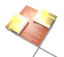
EFD2455A3S-10MHF1
RF Antenna, 4.9 to 5.9GHz, WiFi / MIMO, 3dBi, Linear Horizontal / Vertical, MHF1 / UFL Connector
⚠️ Reference pricing provided. In case of supply shortages, we will connect you with our trusted procurement partners to ensure your project's continuity.
- Manufacturer: EZURIO
- Product type:
- Gain: 3dBi
- SVHC: To Be Advised
- VSWR: 3
- Input Power: 10W
- Antenna Type: WiFi / MIMO
- Frequency Max: 5.9GHz
- Frequency Min: 4.9GHz
- Product Range: FlexPIFA Series
- Input Impedance: 50ohm
- Antenna Mounting: MHF1 / UFL Connector
- Antenna Polarisation: Linear Horizontal / Vertical
| Delivery and price | |
|---|---|
| Units per pack | 250 |
| Price | 6.16 € |
| Current stock | 50+ |
| Lead time | 30 days |
Datasheet

A
The world’s first Flexible PIFA antenna for Wi-Fi MIMO applications (patented). The FlexPIFA MIMO is specifically designed for 802.11 a/b/g/n as well as 802.11ac Wi-Fi modules that use MIMO or Wi-Fi Diversity. The flexible PIFA design provides for consistent performance across a broad array of enclosures and enables adhering the antenna to flat and curved surfaces. The FlexPIFA MIMO drastically simplifies the size, cost, and technical requirements for implementing the two antennas required for 802.11 MIMO radio applications; the proper orientation and spacing between the two integrated antenna elements is already optimized for MIMO radio performance, giving you the best possible range and throughput. FEATURES AND BENEFITS ▪ Two Integrated 2.4/5 GHz dual band elements ▪ Low ECC performance for best in specifically designed for 802.11 MIMO class throughput and range applications performance
- Laird Connectivity’s patented flexible PIFA antenna structure allows for use on flat and curved surfaces
- Simple installation with optimized antenna orientation and spacing
- ▪ US Patent #10.763.578
- Compact design versus the complexity of two separate antennas
|OperatingFrequency (MHz)||2400 - 2480<br>~~Pe~~|2400 - 2480<br>~~Pe~~|||4900 - 5900|
|---|---|---|---|---|---|---|
|Peak Gain – Typ (dBi)||1.7<br>~~PC~~||||2.5|
|Peak Gain – Max(dBi)||2.0<br>~~Ce~~||||3|
|VSWR Port 1(Typ)|||<2.3:1|||<2.8:1|
|VSWR Port 2(Typ)||<2.3:1<br>~~Ce~~||||<2.8:1|
|VSWR(Max)|||<2.5:1|||<3.0:1|
|Isolation,dB(Typ)||>19<br>~~Ce~~||||>19|
|Max Gain ±30 above Horizon(dBi)||N/A<br>~~Pe~~||||2.2|
|Nominal Impedance(Ohms)|||50||||
|Max Power@25°C(Watts)|||10||||
|Polarization|||Linear H/V for each radiator|Linear H/V for each radiator|||
|Azimuth Beam Width|||Omnidirectional||||
||||||||
||||||||
|Dimensions~~–~~mm(in.)|||33.25 x 33.25 x 4.44|33.25 x 33.25 x 4.44(1.309 x 1.309 x .170|1.309 x 1.309 x .170)||
|Weight –g (oz.)|||2.5(0.088)||||
||||||||
|ENVIRONMENTAL SPECIFICATIONS|||||||
|OperatingTemperature|||-40°C to +85°C|(-40°F to +185°F)|||
|Storage Temperature|||-40°C to +85°C|(-40°F to +185°F)|||
|Material Substance Compliance|||RoHS Compliant||||
|CONFIGURATION<br>~~PART NUMBER~~|~~|~~||~~CABLE LENGTH~~<br>~~|~~||~~CONNECTOR~~||
|EFD2455A3S-10MHF1||100 mm<br>~~Po~~||U.FL or IPEX MHF1|||
|EFD2455A3S-30MHF1|||300 mm|U.FL or IPEX MHF1|||
|EFD2455A3S-10MH4L||100 mm<br>~~PO~~|||IPEX MHF4L||
**Note** : Specifications are based on the 100mm cable length, standard antenna version with MHF1 / U.FL connector. Varying the cable length or type or connector will cause variations in these antenna specifications.
1 © Copyright 2022 Laird Connectivity All Rights Reserved
https://www.lairdconnect.com/
**Americas** : +1-800-492-2320 **Europe** : +44-1628-858-940 **Hong Kong** : +852 2762 4823
2
https://www.lairdconnect.com/
**Americas** : +1-800-492-2320 **Europe** : +44-1628-858-940 **Hong Kong** : +852 2762 4823
© Copyright 2023 Laird Connectivity All Rights Reserved
3
https://www.lairdconnect.com/
**Americas** : +1-800-492-2320 **Europe** : +44-1628-858-940 **Hong Kong** : +852 2762 4823
© Copyright 2023 Laird Connectivity All Rights Reserved
4
https://www.lairdconnect.com/
**Americas** : +1-800-492-2320 **Europe** : +44-1628-858-940 **Hong Kong** : +852 2762 4823
© Copyright 2023 Laird Connectivity
All Rights Reserved
The following image/graphic represents the measurement coordinate system used when capturing the radiation patterns shown;
5 © Copyright 2023 Laird Connectivity All Rights Reserved
https://www.lairdconnect.com/
**Americas** : +1-800-492-2320 **Europe** : +44-1628-858-940 **Hong Kong** : +852 2762 4823
The FlexPIFA is designed to attach to dielectric surfaces encountered in plastic packaging of wireless communications devices. The nominal attachment surface used in its design and characterization is a 100 mm x 100 mm, 1.5-millimeter thick, Polycarbonate sheet. The antenna should be centered within the lateral plane of the dielectric sheet as shown in Figure 1.
**==> picture [103 x 132] intentionally omitted <==**
**----- Start of picture text -----**<br>
Antenna Assembly<br>Centered on<br>100 mm X 100 mm<br>1.5 mm thick<br>polycarbonate<br>= r 2.9 ( Polycarbonate )<br>**----- End of picture text -----**<br>
_**Figure 1: Nominal placement of FlexPIFA MIMO Antenna array on 100 mm X 100 mm, 1.5 mm thick, polycarbonate sheet**_
6 © Copyright 2023 Laird Connectivity All Rights Reserved
https://www.lairdconnect.com/
**Americas** : +1-800-492-2320 **Europe** : +44-1628-858-940 **Hong Kong** : +852 2762 4823
The recommended minimum spacing between the ground plane and the antenna array is 5 millimeters to minimize any performance degradations to the reflection parameters (VSWR, Return Loss), spatially averaged gain (efficiency), or peak spatial gain (directivity). The drawings presented in Figure 2 and Figure 3 represent the proper clearance between the antenna array and a co-planar and edge-coupled ground plane.
**==> picture [308 x 324] intentionally omitted <==**
**----- Start of picture text -----**<br>
Antenna Assembly<br>Centered on<br>100 mm X 100 mm<br>100 mm X 100 mm 1.5 mm thick<br>Ground plane polycarbonate<br>a n<br>5.00mm.<br>= r 2.9 ( Polycarbonate )<br>**----- End of picture text -----**<br>
_**Figure 2: Minimum clearance between co-planar edge-coupled ground planes for one placement instance**_
7 © Copyright 2023 Laird Connectivity All Rights Reserved
https://www.lairdconnect.com/
**Americas** : +1-800-492-2320 **Europe** : +44-1628-858-940 **Hong Kong** : +852 2762 4823
**==> picture [275 x 190] intentionally omitted <==**
**----- Start of picture text -----**<br>
Antenna Assembly<br>Centered on<br>100 mm X 100 mm<br>1.5 mm thick<br>polycarbonate<br>= r 2.9 ( Polycarbonate )<br>100 mm X 100 mm<br>Ground plane<br>5.00mm.<br>**----- End of picture text -----**<br>
_**Figure 3: Minimum clearance between co-planar edge-coupled ground planes for another placement instance**_
We recommend that a parallel ground plane not be placed either above or below the antenna array because it degrades the designed peak gain. Increased peak gain can have implications in consequent radio certifications since a maximum declared peak gain is specified as a test condition during the certification testing. Antenna with peak gain beyond the declared value for the certification can cause the device to be noncompliant.
A parallel dielectric sheet can be placed over the antenna with a minimum of ten millimeters as shown in Figure 4 **: Minimum clearance of dielectric sheet loading on top of the antenna array** .
8 © Copyright 2023 Laird Connectivity All Rights Reserved
https://www.lairdconnect.com/
**Americas** : +1-800-492-2320 **Europe** : +44-1628-858-940 **Hong Kong** : +852 2762 4823
**==> picture [403 x 417] intentionally omitted <==**
**----- Start of picture text -----**<br>
Antenna Assembly<br>Centered on<br>100 mm X 100 mm<br>1.5 mm thick<br>polycarbonate<br>= r 2.9 ( Polycarbonate )<br>Minimum Spacing<br>between two 100 mm X<br>100 mm<br>1.5 mm polycarbonate<br>sheets = 10 mm<br>= r 2.9 ( Polycarbonate )<br>= r 2.9 ( Polycarbonate )<br>Antenna Assembly<br>Centered on<br>100 mm X 100 mm<br>1.5 mm thick<br>polycarbonate<br>10.00mm.<br>**----- End of picture text -----**<br>
_**Figure 4: Minimum clearance of dielectric sheet loading on top of the antenna array**_
9 © Copyright 2023 Laird Connectivity All Rights Reserved
https://www.lairdconnect.com/
**Americas** : +1-800-492-2320 **Europe** : +44-1628-858-940 **Hong Kong** : +852 2762 4823
One of the benefits of the flexible nature of antenna array is that it can be placed on curved surfaces. The array was tested on both convex and concave curved surfaces with radii of curvature of 37.5 millimeters and 33 millimeters, respectively. The testing was performed using a 75millimeter nominal OD (outside diameter), PVC (Polyvinyl chloride) pipe with an average thickness of 2.5 millimeters.
**==> picture [78 x 295] intentionally omitted <==**
**----- Start of picture text -----**<br>
Antenna Assembly<br>Placed on Interior of 75<br>mm OD PVC Pipe<br>Radius of Curvature =<br>37.5 mm<br>= r 3 ( PVC )<br>Antenna Assembly<br>Placed on Interior of 75<br>mm OD PVC Pipe<br>Radius of Curvature =<br>33 mm<br>—<br>**----- End of picture text -----**<br>
_**Figure 5: Operation of the antenna array on a dielectric curved surface**_
## **We recommend the following:**
- Initial placement: Place on any dielectric sheet or surface
-
- Nominal material thickness – 1.5 mm
- Relative dielectric constant – Approximately 3
- Clearance to Co-planar, edge-coupled ground planes – 5 mm (minimum)
- Clearance to Parallel Ground Planes – Not recommended
- Clearance to Parallel Dielectric Sheet above antenna array – 10 mm
- Operation on curved surfaces:
- Convex radius of curvature – 37.5 mm (typical)
- Concave radius of curvature – 33 mm (typical)
10 © Copyright 2023 Laird Connectivity All Rights Reserved
https://www.lairdconnect.com/
**Americas** : +1-800-492-2320 **Europe** : +44-1628-858-940 **Hong Kong** : +852 2762 4823
Please contact your local Laird Connectivity sales representative or our support team for further assistance:
**Support Center** https://www.lairdconnect.com/resources/support
**Phone** Americas: +1-800-492-2320 Europe: +44-1628-858-940 Hong Kong: +852 2762 4823
**Web** https://www.lairdconnect.com/internal-antennas
**Address** Laird Connectivity 50 S. Main Street, Suite 1100 Akron, OH 44308
© Copyright 2023 Laird Connectivity. All Rights Reserved. Patent pending. Any information furnished by Laird Connectivity and its agents is believed to be accurate and reliable. All sales@lairdconnect.com specifications are subject to change without notice. Responsibility for the use and application of Laird Connectivity materials or products rests with the end user since Laird Connectivity and its agents cannot be aware of all potential uses. Laird Connectivity makes no warranties as to non-infringement nor as to the fitness, merchantability, or sustainability of any Laird Connectivity support@lairdconnect.com materials or products for any specific or general uses. Laird Connectivity or any of its affiliates or agents shall not be liable for incidental or consequential damages of any kind. All Laird www.lairdconnect.com Connectivity products are sold pursuant to the Laird Connectivity Terms and Conditions of Sale in effect from time to time, a copy of which will be furnished upon request. Nothing herein provides a license under any Laird Connectivity or any third-party intellectual property right.
11 © Copyright 2023 Laird Connectivity All Rights Reserved
https://www.lairdconnect.com/
**Americas** : +1-800-492-2320 **Europe** : +44-1628-858-940 **Hong Kong** : +852 2762 4823
Updated at June 9, 2026
About Novapart
Novapart is a B2B electronic component broker specialising in stock shortages and cost reduction. We source hard-to-find parts and identify compliant alternatives across a catalogue of 410,000+ components from 500+ manufacturers.
Learn more →Stock Shortage Specialist
When a component is unavailable, discontinued or has an unacceptable lead time, we tap into our network of vetted European and Asian distributors to source what you need — without compromising on quality or traceability.
Request a quote →Compliant Alternatives
We identify pin-to-pin, electrically equivalent substitutes that meet the same certifications (RoHS, AEC-Q100, REACH) as your original specification — validated against datasheets, not just part numbers. Often at a lower cost.
BOM Analysis service →