
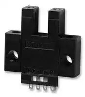


EE-SX670
Photomicrosensor, Slot, Standard, Through Beam, 5 mm, NPN, Dark On, Light On, 5 Vdc to 24Vdc
- Manufacturer: OMRON
- Product type: Optical / Slot Photoelectric Sensors
- Product Range: EE-SX67 Series
- Sensor Output: NPN
- Output Current: 100mA
- Sensing Range Max: 5mm
- Supply Voltage DC Max: 24V
- Supply Voltage DC Min: 5V
| Delivery and price | |
|---|---|
| Units per pack | 20 |
| Price | 22.7 € |
| Current stock | 50+ |
| Lead time | 7 days |
**Slot-type Photomicrosensor (Non-modulated)** *1 **EE-SX47/67**

CSM_EE-SX47_67_DS_E_9_1

## **Global Standard Slot-type photomicrosensors with 50- to 100-mA direct switching capacity.**

• Series includes models that enable switching between dark-ON and light-ON operation. • Response frequency as high as 1 kHz. • Easy operation monitoring with bright light indicator. • Wide operating voltage range: 5 to 24 VDC • Models in which the light indicator turns ON for dark-ON operation are also available. • A wide range of variations in eight different shapes. • Flexible robot cable is provided as a standard feature. *2 Be sure to read _Safety Precautions_ on page 5. ~~| a~~ *1. Pre-wired Models are available only in the EE-SX67 Series. *2. Only for Pre-wired Models.

+4 For the most recent information on models that have been certified for bere safety standards, refer to your OMRON website.

## **Ordering Information**

|**Appearance**<br>~~ey~~<br>~~|)~~|**Sensing**<br>**method**<br>~~TE~~|**Connect-**<br>**ing method**<br>~~TE~~|**Sensing distance**<br>~~TE~~<br>~~|~~|**Sensing distance**<br>~~TE~~<br>~~|~~|**Output**<br>**configuration**<br>~~TE~~<br>~~| —~~|**Indicator mode**<br>~~TE~~|**Model**<br>~~TE~~|**Model**<br>~~TE~~|
|---|---|---|---|---|---|---|---|---|
||||||||**NPN output**<br>~~TE~~|**PNP output**<br>~~TE~~|
|Standard<br>~~ey~~<br>~~|)~~|Through-<br>beam<br>type<br>(with slot)<br>~~TE~~<br>~~Ho~~|Connector<br>(4 poles)<br>~~TE~~<br>~~Ho~~|~~TE~~<br>~~Ho~~|5 mm<br>(slot width)<br>~~TE~~<br>~~|~~<br>~~Ho~~|Dark-ON/Light-ON<br>(selectable)*3<br>~~TE~~<br>~~| —~~|Incident light<br>~~TE~~|**EE-SX670**<br>~~TE~~|**EE-SX670P**<br>~~TE~~|
|||||||No incident light<br>~~TE~~|**EE-SX670A**<br>~~TE~~|**EE-SX670R**<br>~~TE~~|
||||||Light-ON<br>~~TE~~<br>~~| —~~|Incident light<br>~~TE~~|**EE-SX470**<br>~~TE~~|---<br>~~TE~~|
|L-shaped<br>~~ey~~<br>~~|)~~<br>~~y.~~|||||Dark-ON/Light-ON<br>(selectable)*3<br>~~TE~~<br>~~| —~~<br>~~CEE~~|Incident light<br>~~TE~~<br>~~CEE~~|**EE-SX671**<br>~~TE~~<br>~~CEE~~|**EE-SX671P**<br>~~TE~~|
|||||||No incident light<br>~~CEE~~|**EE-SX671A**<br>~~CEE~~|**EE-SX671R**|
||||||Light-ON<br>~~| —~~<br>~~CEE~~|Incident light<br>~~CEE~~|**EE-SX471**<br>~~CEE~~|---|
|T-shaped,<br>slot center<br>7 mm<br>~~y.~~|||||Dark-ON/Light-ON<br>(selectable)*3<br>~~CEE~~<br>~~_—_f~~|Incident light<br>~~CEE~~<br>~~—_f~~|**EE-SX672**<br>~~CEE~~<br>~~—_f~~|**EE-SX672P**|
|||||||No incident light<br>~~CEE~~<br>~~—_f~~|**EE-SX672A**<br>~~CEE~~<br>~~—_f~~|**EE-SX672R**|
||||||Light-ON<br>~~CEE~~<br>~~_—_f~~|Incident light<br>~~CEE~~<br>~~—_f~~|**EE-SX472**<br>~~CEE~~<br>~~—_f~~|---|
|Close-<br>mounting<br>~~y.~~<br>~~Ho~~|||||Dark-ON/Light-ON<br>(selectable)*3<br>~~CEE~~<br>~~_—_f~~<br>~~Hoo~~|Incident light<br>~~CEE~~<br>~~—_f~~<br>~~o~~|**EE-SX673**<br>~~CEE~~<br>~~—_f~~<br>~~o~~|**EE-SX673P**|
|||||||No incident light<br>~~o~~|**EE-SX673A**<br>~~o~~|**EE-SX673R**|
||||~~Ho~~||Light-ON<br>~~Hoo~~|Incident light<br>~~o~~|**EE-SX473**<br>~~o~~|---|
||||~~Ho~~||||||
|Close-<br>mounting<br>~~Ho~~<br>’<br>~~te~~<br>~~7~~|||||Dark-ON/Light-ON<br>(selectable)*3<br>~~Hoo~~<br>~~———~~|Incident light<br>~~o~~<br>~~———~~|**EE-SX674**<br>~~o~~<br>~~———~~|**EE-SX674P**|
|||||||No incident light<br>~~———~~|**EE-SX674A**<br>~~———~~|**EE-SX674R**|
||||||Light-ON<br>~~———~~<br>~~|~~|Incident light<br>~~———~~<br>~~|~~<br>~~|~~|**EE-SX474**<br>~~———~~<br>~~|~~<br>~~|~~|---|
|T-shaped,<br>slot center<br>10 mm<br>~~te~~<br>~~7~~<br>~~¥~~|||||Dark-ON/Light-ON<br>(selectable)*3<br>~~|~~|Incident light<br>~~|~~<br>~~|~~<br>~~**|**~~|**EE-SX675**<br>~~|~~<br>~~|~~<br>~~**|**~~|**EE-SX675P**|
|F-shaped<br>~~te~~<br>~~7~~<br>~~¥~~|||||Dark-ON/Light-ON<br>(selectable)*3<br>~~|~~<br>~~|~~|Incident light<br>~~|~~<br>~~|~~<br>~~|~~<br>~~**|**~~|**EE-SX676**<br>~~|~~<br>~~|~~<br>~~|~~<br>~~**|**~~|**EE-SX676P**|
|R-shaped<br>~~¥~~|||||Dark-ON/Light-ON<br>(selectable)*3<br>~~|~~|Incident light<br>~~**|**~~|**EE-SX677**<br>~~**|**~~|**EE-SX677P**|


*3. Dark-ON when the L terminal of the connector is opened, and light-ON when the L terminal and positive (+) terminal are connected. Do not connect the L terminal to 0 V when using dark-ON operation. When using light-ON, it is useful to select the connector EE-1001-1. The L terminal and positive (+) terminal of this connector are connected in advance.

**1** ~~a~~

**EE-SX47/67**

## **Pre-wired Models**

Infrared light

|**Appearance**|**Sensing**<br>**method**|**Sensing distance**|**Sensing distance**|**Output**<br>**configura-**<br>**tion**|**Indicator**<br>**mode**|**Connecting**<br>**method**|**Model**|**Model**|
|---|---|---|---|---|---|---|---|---|
||||||||**NPN output**|**PNP output**|
|Standard<br>~~dy~~|Through-<br>beam<br>type<br>(with slot)<br>~~¥~~<br>~~<~~<br>~~b~~<br>~~]~~|~~¥~~|5 mm<br>(slot width)<br>~~¥~~<br>~~<~~<br>~~b~~<br>~~]~~|Dark-ON/<br>Light-ON<br>(selectable)*<br>~~¥~~<br>~~<~~<br>~~b~~<br>~~]~~|Incident<br>light<br>~~¥~~<br>~~<~~<br>~~b~~<br>~~]~~|Pre-wired<br>Models (1m)<br>~~¥~~<br>~~<~~<br>~~b~~<br>~~]~~|**EE-SX670-WR 1M **<br>~~a~~|**EE-SX670P-WR**<br>**1M**|
|L-shaped<br>~~dy~~|||||||**EE-SX671-WR 1M **<br>~~a~~<br>~~os~~|**EE-SX671P-WR**<br>**1M**|
|T-shaped,<br>slot center<br>7 mm<br>~~y:~~|||||||**EE-SX672-WR 1M **<br>~~os~~<br>~~a~~|**EE-SX672P-WR**<br>**1M**|
|Close-<br>mounting<br>~~y:~~<br>~~¥~~|||||||**EE-SX673-WR 1M **<br>~~a~~<br>~~¥a~~|**EE-SX673P-WR**<br>**1M**<br>~~¥a~~|
|||~~¥~~|||||||
|Close-<br>mounting<br><br>~~<~~||~~<~~<br>~~b~~<br>~~]~~|||||**EE-SX674-WR 1M **<br>~~a~~<br>~~<~~<br>~~a~~|**EE-SX674P-WR**<br>**1M**<br>~~a~~|
|T-shaped,<br>slot center<br>10 mm<br>~~b~~|||||||**EE-SX675-WR 1M **<br>~~a~~<br>~~ba~~|**EE-SX675P-WR**<br>**1M**<br>~~ba~~|
|F-shaped<br><br>~~]~~|||||||**EE-SX676-WR 1M **<br>~~a~~<br>~~]~~<br>~~a~~|**EE-SX676P-WR**<br>**1M**<br>~~a~~|
|R-shaped<br>"|||||||**EE-SX677-WR 1M **|**EE-SX677P-WR**<br>**1M**|


|**Type**|**Type**|**Cable**<br>**length**<br>~~—[~~|**Model**<br>~~—[~~|**Remarks**|
|---|---|---|---|---|
|Connector<br>Connector with Cable<br>1 m<br>2 m<br>Connector with Robot<br>Cable<br>1 m<br>2 m<br>~~—[~~<br>~~[Fr E=~~<br>~~So~~|||**EE-1001**<br>~~—[~~||
||||**EE-1001-1**<br>~~E=~~|L terminal and positive (+) terminal are already short-circuited.|
||||**EE-1009**<br>~~E=~~||
||Connector with Cable<br>~~[Fr~~|1 m<br>~~[Fr E=~~|**EE-1006 1M**<br>~~E=~~||
||||**EE-1010 1M**<br>~~E=~~||
|||2 m<br>~~[Fr E=~~|**EE-1006 2M**<br>~~E=~~||
||||**EE-1010 2M**<br>~~E=~~||
||Connector with Robot<br>Cable<br>~~[Fr~~<br>~~So~~|1 m<br>~~[Fr E=~~<br>~~So~~|**EE-1010-R 1M**<br>~~E=~~<br>~~So~~||
|||2 m<br>~~[Fr E=~~<br>~~So~~|**EE-1010-R 2M**<br>~~E=~~<br>~~So~~||
|Connector Hold-down Clip<br>~~So~~|||**EE-1006A**<br>~~So~~|For EE-1006 only.|


* Refer to _Accessories_ for details.

**2** ~~a~~

**EE-SX47/67**

## **Ratings and Specifications**

|**Item**||**Type**|**Standard**|**L-shaped**|**T-shaped,**<br>**slot center**<br>**7 mm**|**Close-mounting**|**Close-mounting**|**T-shaped,**<br>**slot center**<br>**10 mm**|**F-shaped**|**R-shaped**|
|---|---|---|---|---|---|---|---|---|---|---|
||**NPN**<br>**models**|**Connector**<br>**models**|**EE-SX670**<br>**EE-SX670A**<br>**EE-SX470**|**EE-SX671**<br>**EE-SX671A**<br>**EE-SX471**|**EE-SX672**<br>**EE-SX672A**<br>**EE-SX472**|**EE-SX673**<br>**EE-SX673A**<br>**EE-SX473**|**EE-SX674**<br>**EE-SX674A**<br>**EE-SX474**|**EE-SX675**|**EE-SX676**|**EE-SX677**|
|||**Pre-wired**<br>**models**|**EE-SX670-**<br>**WR**|**EE-SX671-**<br>**WR**|**EE-SX672-**<br>**WR**|**EE-SX673-**<br>**WR**|**EE-SX674-**<br>**WR**|**EE-SX675-**<br>**WR**|**EE-SX676-**<br>**WR**|**EE-SX677-**<br>**WR**|
||**PNP**<br>**models**|**Connector**<br>**models**|**EE-SX670P**<br>**EE-SX670R**|**EE-SX671P**<br>**EE-SX671R**|**EE-SX672P**<br>**EE-SX672R**|**EE-SX673P**<br>**EE-SX673R**|**EE-SX674P**<br>**EE-SX674R**|**EE-SX675P**|**EE-SX676P**|**EE-SX677P**|
|||**Pre-wired**<br>**models**|**EE-SX670P-**<br>**WR**|**EE-SX671P-**<br>**WR**|**EE-SX672P-**<br>**WR**|**EE-SX673P-**<br>**WR**|**EE-SX674P-**<br>**WR**|**EE-SX675P-**<br>**WR**|**EE-SX676P-**<br>**WR**|**EE-SX677P-**<br>**WR**|
|**Sensing distance**|||5 mm(slot width)||||||||
|**Sensing object**|||Opaque: 2×0.8 mm min.||||||||
|**Differential distance**|||0.025 mm||||||||
|**Light source**|||Infrared LED with apeak wavelength of 940 nm||||||||
|**Indicator*1**|||Light indicator(red) (turns ON when light is interrupted for models with A or R suffix)||||||||
|**Supply voltage**|||5 to 24 VDC ±10%, ripple(p-p): 10% max.||||||||
|**Current consumption**|||12 mA max.(Connector models), 35 mA max.(NPNpre-wired models), 30 mA max.(PNPpre-wired models)||||||||
|**Control output**|||NPN open collector: 5 to 24 VDC, 100 mA max.<br>100 mA load current with a residual voltage of 0.8 V max.<br>40 mA load current with a residual voltage of 0.4 V max.<br>OFF current (leakage current): 0.5 mA max.<br>PNP open collector: 5 to 24 VDC, 50 mA max.<br>50 mA load current with a residual voltage of 1.3 V max.<br>OFF current(leakage current): 0.5 mA max.||||||||
|**Protection circuits**|||Load short circuitprotection(Connector models), No circuitprotection(Pre-wired models)||||||||
|**Response frequency *2**|||1 kHz min.(3 kHz average)||||||||
|**Ambient illumination**|||1,000 lx max. with fluorescent light on the surface of the receiver.||||||||
|**Ambient temperature range**|||Operating:−25 to +55°C, Storage:−30 to +80°C(with no icingor condensation)||||||||
|**Ambient humidity range**|||Operating: 5% to 85%, Storage: 5% to 95%(with no icingor condensation)||||||||
|**Vibration resistance**|||Destruction: 20 to 2,000 Hz (peak acceleration: 100 m/s2)<br>1.5-mm double amplitude for 2 h(4-minperiods)each in X, Y, and Z directions||||||||
|**Shock resistance**|||Destruction: 500 m/s2for 3 times each in X, Y, and Z directions||||||||
|**Degree ofprotection**|||IEC60529 IP50||||||||
|**Connecting method**|||Connector Models (direct soldering possible), Pre-wired Models (Standard cable length: 1 m),<br>Models with Connectors(Standard cable length: 0.1 m)||||||||
|**Wei-**<br>**ght**|**Connector models**||Approx. 3.1g|Approx. 3g|Approx. 2.4g|Approx. 2.3g|Approx. 3g|Approx. 2.7g|Approx. 2.2g|Approx. 2.2g|
||**Pre-wired models**||Approx. 18.9g|Approx. 17.3g|Approx. 17.8g|Approx. 16.8g|Approx. 17.1g|Approx. 18.3g|Approx. 16.9g|Approx. 16.9g|
|**Ma-**<br>**teri-**<br>**al**|**Case**||Polybutylenephthalate(PBT)||||||||
||**Cover**||Polycarbonate||||||||
||**Emitter/receiver**||||||||||


*1. The indicator is a GaP red LED (peak wavelength: 690 nm).

*2. The response frequency was measured by detecting the rotating disk shown at the right.

**==> picture [143 x 50] intentionally omitted <==**

**----- Start of picture text -----**<br>
Disk<br>2.1 mm1 mm 1 mm<br>t = 0.2 mm<br>**----- End of picture text -----**<br>


**3**

**EE-SX47/67**

## **Engineering Data (Reference Value)**

**==> picture [306 x 10] intentionally omitted <==**

**----- Start of picture text -----**<br>
Sensing Position Characteristics Sensing Position Characteristics<br>**----- End of picture text -----**<br>


## **Repeated Sensing Position Characteristics**

**==> picture [490 x 178] intentionally omitted <==**

**----- Start of picture text -----**<br>
d<br>Dark-ON Dark-ON<br>Tr ON Tr ON OFF<br>Δd2<br>Δd3 Δd1<br>Δd4<br>d Δd5<br>d<br>ON<br>Ta = −25°C Ta = 55°C Ta = 25°C<br>Tr OFF Tr OFF<br>0 1.0 2.0 3.0 4.0 5.0 6.0 0 1.0 2.0 3.0 4.0 5.0 6.0 0  3.20  3.22  3.24  3.26  3.28<br>Distance d (mm) Distance d (mm) Distance d (mm)<br>Vcc =12 V, No. of repetitions: 20,  Δ d1 = 0.002 mm,<br>Δ d2 = 0.004 mm,  Δ d3 = 0.005 mm,  Δ d4 = 0.02 mm,<br>Δ d5 = 0.04 mm<br>Output level transistor<br>**----- End of picture text -----**<br>


Note: The data applies to dark status. Operation may be affected by external light interference or light coming through the sensing object.

## **I/O Circuit Diagrams**

## **NPN Output**

**==> picture [512 x 369] intentionally omitted <==**

**----- Start of picture text -----**<br>
Model confiOutput guration Timing charts connectionsTerminal  Output circuit<br>Incident<br>Light indicatorInterruptedON Short-circuited  EE-SX67 @<br>Light-ON  (red)Output  OFFON L  terminal and between  EE-SX67 @ A<br>transistor OFF positive   terminal Light indicator  *<br>Load  Operates (red)<br>EE-SX67@ (e.g., relay) Releases L  Load<br>EE-SX67@-WR Incident OUT  5 to<br>Light indicatorInterruptedON Open between  circuit Main   IC  (Control output) 100 mA max.  24 VDC<br>Dark-ON (red) OFF L  terminal and<br>Output  ON positive   terminal<br>transistor OFF *1<br>Load Operates *The terminal arrangement depends on the model.<br>(e.g., relay) Releases  Check the dimensional diagrams.<br>Incident EE-SX67 @ -WR<br>EE-SX670A Light-ON Light indicator(red)Output transistor InterruptedOFFOFFONON positive Short-circuited L  terminal and between  terminal Light indicator(red) L * Load<br>EE-SX671AEE-SX672A (e.g., relay)Load ReleasesOperates circuitMain  OUTIC (Control output) 5 to 24 VDC<br>100 mA max.<br>EE-SX673A Incident<br>EE-SX674A Light indicatorInterruptedON Open between<br>Dark-ON (red)Output transistor OFFOFFON positive L  terminal and *1 terminal *The terminal arrangement depends on the model.  Check the dimensional diagrams.<br>Load  Operates<br>(e.g., relay) Releases<br>Incident Light indicator(red)<br>EE-SX470 Interrupted Load<br>EE-SX471 Light indicator ON<br>EE-SX472EE-SX473 Light-ON (red)Outputtransistor OFFOFFON --- circuitMain  OUTIC 5 to 24 VDC<br>EE-SX474 Load  Operates<br>(relay) Releases<br>**----- End of picture text -----**<br>


- *1. Do not connect the L terminal to 0 V when using dark-ON operation.

**4**

**EE-SX47/67**

## **PNP Output**

|**Model**|**Output**<br>**configuration**|**Timing charts**|**Terminal**<br>**connections**|**Output circuit**|
|---|---|---|---|---|
|EE-SX67@P<br>EE-SX67@P-WR|Light-ON|Incident<br>Interrupted<br>ON<br>OFF<br>ON<br>OFF<br>Operates<br>Releases<br>Light indicator<br>(red)<br>Output<br>transistor<br>Load<br>(relay)<br>~~on~~<br>~~mm~~<br>~~=~~|Short-circuited<br>between<br>terminal and<br>positive<br>terminal<br>L<br>|°|5 to<br>24 VDC<br>Load<br>Main<br>circuit<br>L<br>OUT<br>IC<br>Light indicator<br>(red)<br>*<br>*The terminal arrangement depends on the model.<br>Check the dimensional diagrams.<br>Cy)6<br>de<br>~~6 tt ~~be:<br>| ~~ia~~<br>:<br>~~o~~a|
||Dark-ON|Incident<br>Interrupted<br>ON<br>OFF<br>ON<br>OFF<br>Operates<br>Releases<br>Light indicator<br>(red)<br>Output<br>transistor<br>Load<br>(relay)<br>~~=~~<br>~~me~~<br>|<br>~~—~~<br>~~==~~|Open between<br>terminal and<br>positive<br>terminal<br>*1<br>L<br>o<br>*||
|EE-SX670R<br>EE-SX671R<br>EE-SX672R<br>EE-SX673R<br>EE-SX674R|Light-ON|Incident<br>Interrupted<br>ON<br>OFF<br>ON<br>OFF<br>Operates<br>Releases<br>Light indicator<br>(red)<br>Output<br>transistor<br>Load<br>(e.g., relay)<br>~~=~~ ~~=~~<br>~~mm~~<br>~~ae~~|Short-circuited<br>between<br>terminal and<br>positive<br>terminal<br>L<br>|°<br>©||
||Dark-ON|Incident<br>Interrupted<br>ON<br>OFF<br>ON<br>OFF<br>Operates<br>Releases<br>Light indicator<br>(red)<br>Output<br>transistor<br>Load<br>(e.g., relay)<br>~~_~~<br>~~@W~~o<br>~~=~~<br>~~»~~|Open between<br>terminal and<br>positive<br>terminal<br>*1<br>L<br>o<br>©||


*1. Do not connect the L terminal to 0 V when using dark-ON operation.

## **Safety Precautions**

## **Refer to** _**Warranty and Limitations of Liability**_ **.**

## **WARNING**

**This product is not designed or rated for ensuring safety of persons either directly or indirectly. Do not use it for such purposes.**

## **Precautions for Correct Use** ~~fo~~

Make sure that this product is used within the rated ambient environment conditions.

## ● **Installation**

- When direct soldering to the terminals, use the following guidelines.

## **Precautions for Safe Use**

## ● **Operating Environment**

These Photomicrosensors have an IP50 (conforms to IEC) enclosure and do not have a water-proof or dust-proof structure. Therefore, do not use them in applications in which the sensor will be subjected to splashes from water, oil, or any other liquid. Liquid entering the Sensor may result in malfunction.

Soldering Conditions

**Item TemperPermissible Remarks ature time** Soldering iron 350°Cmax. 3 s max. The portion between the base of the terminals and the position 1.5 mm from the terminal base must not be soldered. ~~a~~

• The terminal base uses a polycarbonate resin, which could be deformed by excessive soldering heat, resulting in damage to the product's functionality.

## ● **Lot Number and Model Number Legend**

> In the following diagrams, 343U **EE-SX** @ **70** @ indicates the lot number and factory where the product was Model number manufactured. Do not include this EE-SX670 code with the model number when 343U ordering. The QR code on connector models is used by OMRON only. ~~aarEE~~ T Lot number and factory code

**5**

**EE-SX47/67**

(Unit: mm)

## **Dimensions**

Tolerance class IT16 applies to dimensions in this datasheet unless otherwise specified.

## **Sensors**

**==> picture [513 x 656] intentionally omitted <==**

**----- Start of picture text -----**<br>
EE-SX671/671P<br>EE-SX670/670P Terminal Arrangement<br>EE-SX671A/671R<br>EE-SX670A/670R Terminal Arrangement EE-SX471 (1) Vcc<br>EE-SX470 (1) Vcc (2) L L*<br>(2) L L* (3) OUT OUTPUT<br>(3) OUT OUTPUT (4) GND (0 V)<br>(4) GND (0 V) * Pin 2 is not used for the EE-SX471.<br>* Pin 2 is not used for the EE-SX470.<br>26.2<br>25.4 19 Four, R2<br>19<br>Two, 3.2 dia.<br>holes 3.2<br>6.95 14.5<br>3 Four, R1<br>3<br>Four, R1<br>13.419 6.40.8 6.2 3.8<br>5 Indicator window<br>1 2 3 4<br>2.54<br>9 Optical axis 2 13.413 6.35<br>0.8<br>13.8 5<br>8.4<br>13.2 5.5 Two, 3.8 dia. holes 9 8.3 9 Optical axisTwo, 3.2 dia. holes2.1 0.3 2 15.5<br>6.2 3.8 Indicator window 7.2 6.2 7.2<br>3.6 0.7<br>1 2 3 4<br>2.54 0.3 0.7 13 0.6 6.95<br>13.4<br>19<br>EE-SX672/672P EE-SX673/673P<br>EE-SX672A/672R Terminal Arrangement EE-SX673A/673R Terminal Arrangement<br>EE-SX472 (1) Vcc EE-SX473 (1) Vcc<br>(2) L L* (2) L L*<br>(3) OUT OUTPUT (3) OUT OUTPUT<br>(4) GND (0 V) (4) GND (0 V)<br>* Pin 2 is not used for the EE-SX472. * Pin 2 is not used for the EE-SX473.<br>13.7<br>3<br>26 6.4 12.6 6.3<br>12.8 (6.65)<br>3.5<br>Two, R1 7 Two, 3.2 dia. holes<br>7<br>0.8 13.4 13.4<br>0.8<br>2 5 5<br>9 Optical axisIndicator window 9 Optical axis 2<br>13 4.3 Four, R1.6 22.2 3 22.2 14.4<br>8.4<br>6.2 2.8<br>6.3 6.3<br>2.5 4.9<br>Four, R1<br>6.2 3.8 6.2 3.8 Indicator window<br>2.5<br>0.3 0.7 1 2 32.544 1 2 3 4 2.54 0.3 0.7<br>19 13<br>**----- End of picture text -----**<br>


**6**

**EE-SX47/67**

**==> picture [508 x 651] intentionally omitted <==**

**----- Start of picture text -----**<br>
EE-SX674/674P EE-SX675/675P<br>EE-SX674A/674R<br>EE-SX474 Terminal Arrangement Terminal Arrangement<br>(1) Vcc (1) Vcc<br>(2) L L* (2) L L<br>(3) OUT OUTPUT (3) OUT OUTPUT<br>(4) GND (0 V) (4) GND (0 V)<br>* Pin 2 is not used for the EE-SX474.<br>16.7<br>Optical axis 4<br>Two, R1 7 Two,  3.5 dia. holes 6.35 26<br>Indicator window<br>7 10<br>21.5 6.95 eS a|<br>PLA |<br>3 0.8 13.4<br>3 5 Optical axis<br>Sensing<br>6.2 3.8 g y window ae<br>9 Indicator window<br>1 2 3 4 2<br>2.54135 0.8 0.1 13 6 (R) 3.7 (R) 22.2 8.4 3<br>6.3<br>(2.9) Optical axis 2 3.2 2.5<br>(9.3) 3.8<br>2.1 0.3 15.5 0.7 6.2<br>6.2 0.3 1 2 3 4<br>0.7 2.6 19.5 2.54<br>13<br>SP 13.6 0.6 = 16.7<br>EE-SX676/676P EE-SX677/677P<br>Terminal Arrangement Terminal Arrangement<br>(1) Vcc (1) Vcc<br>(2) L L (2) L L<br>(3)(4) _—|_| OUT GND (0 V)OUTPUT (3)(4) —_Pe] OUT GND (0 V)OUTPUT<br>élObnt beeo<br>13.7<br>Optical axis 13.7<br>Optical axis<br>2.5 on acy<br>2.5<br>Te 7 13.4 _ 13.27 6.35 7 13.26.35 Sensing  window = 7<br>5 . Optical axis = 0.8 0.8 7 7 - 13.45 Optical axis<br>9<br>Machai LI | Indicator window 9 . 2 2 an 9 | as 9 tae Indicator window<br>22.2 3 22.2 3<br>8.4 Sensing  8.4<br>rT | 13.6 7 | window | 7 13.6 | ,<br>2.5 2.5<br>6.2 | 3.8 He 3.3 HD]O| || olQe 3.3 6.2 m 3.8 e a:ll<br>1 2 3 4 0.3 0.3 1 2 3 4<br>= 2.54 Two, 3.5 dia. holes a 0.7 0.7 Two, 3.5 dia. holes = 2.54<br>**----- End of picture text -----**<br>


**7** ~~a~~

**EE-SX47/67**

## **EE-SX670-WR/670P-WR**

**==> picture [103 x 8] intentionally omitted <==**

**----- Start of picture text -----**<br>
EE-SX671-WR/671P-WR<br>**----- End of picture text -----**<br>


**==> picture [501 x 658] intentionally omitted <==**

**----- Start of picture text -----**<br>
Terminal Arrangement Terminal Arrangement<br>Brown Vcc Brown Vcc<br>Pink L Pink L<br>Blue GND (0 V) Blue GND (0 V)<br>Black OUTPUT Black OUTPUT<br>26.2<br>R1 R3.5 19 Optical axis<br>Optical axis<br>6.95 3.2 6.95<br>19 R1 3 18.7<br>3<br>3.2 dia.<br>Indicator window<br>25.4<br>aT | 2<br>13.45 Optical axis 0.8 6.35<br>13.4 Robot cable of 2.8 dia., 4 cores,<br>(0.15 mm [2 ] with 0.8 mm dia. insulator);<br>9 2 Standard length: 1 m<br>11.2<br>6.35<br>13.8 Sensing  13.4<br>26.2 8.4 rt m 3 n window a _ 5 Optical axis Sensing window 0.8 |<br>11<br>2.5 5.5 9 2<br>15.5 9 4.6 dia. 2.8 6.2<br>2 4.6 dia. 3.8 dia. 7.2<br>Indicator window Robot cable of 2.8 dia., 4 cores,  3.6 19<br>(0.15 mm [2 ] with 0.8 mm dia. insulator); 3.2 dia.<br>| Standard length: 1 m<br>EE-SX672-WR/672P-WR EE-SX673-WR/673P-WR<br>Terminal Arrangement Terminal Arrangement<br>Brown Vcc Brown Vcc<br>Pink L Pink L<br>Blue GND (0 V) Blue GND (0 V)<br>Black OUTPUT Black OUTPUT<br>13.7<br>7<br>Optical axis<br>12.6<br>6.3<br>Optical axis 12.8 3.5 (6.65)<br>aE rE<br>3 R1 7 3.2 dia.<br>1 13.4<br>6.35 13.4 5 Optical axis 0.8<br>Sensing  0.8 5<br>window<br>Pr Optical axis +f 2 e y<br>9<br>2<br>4.3 9 Indicator  14.4 2 dia. Sensing window<br>13 2.5 window 26.2<br>R1.6 26.2 8.4<br>6.2 8.9 2.8 Indicator window<br>3<br>10.3 R1 2.5<br>2 2 Robot cable of 2.8 dia., 4 cores,<br>(0.15 mm [2 ] with 0.8 mm dia. insulator);<br>Robot cable of 2.8 dia., 4 cores,  Standard length: 1 m<br>4.6 dia.<br>(0.15 mm [2 ] with 0.8 mm dia. insulator); 4.6 dia.<br>19 Standard length: 1 m<br>A<br>26<br>**----- End of picture text -----**<br>


**8** ~~a~~

**EE-SX47/67**

**==> picture [510 x 672] intentionally omitted <==**

**----- Start of picture text -----**<br>
EE-SX674-WR/674P-WR EE-SX675-WR/675P-WR<br>Terminal Arrangement Terminal Arrangement<br>Brown Vcc Brown Vcc<br>Pink L Pink L<br>Blue GND(0V) Blue GND(0V)<br>Black OUTPUT Black OUTPUT<br>€ =— bbe =—<br>3.5 dia. 7 R1 Optical axis 10<br>6.35 26<br>7<br>7 4<br>6.95<br>25.7<br>Optical axis 3 Bel aig:<br>3 19.5 13.4<br>0.8 Sensing  5<br>2 window Optical axis<br>Indicator window 2 9<br>Indicator window<br>Robot cable of 2.8 dia., 4 cores,  (R) 13<br>__ (0.15 mm [2 ] with 0.8 mm dia. insulator); TA 3<br>Standard length: 1 m 26.2 8.4<br>6 3.2<br>13.6<br>2.5<br>5 Optical axis Sensing window 0.8 3.7 10.3<br>(R)<br>(2.9) 2<br>9 2 4.6 dia.<br>anger a ale]<br>4.6 dia. 15.5<br>2.6 Robot cable of 2.8 dia., 4 cores,<br>6.2 2.8 (0.15 mm [2 ] with 0.8 mm dia. insulator); 13.4<br>Standard length: 1 m<br>16.7<br>MP ie) O R<br>EE-SX676-WR/676P-WR EE-SX677-WR/677P-WR<br>Terminal Arrangement Terminal Arrangement<br>Brown Vcc Brown Vcc<br>Pink L Pink L<br>Blue GND(0V) Blue GND(0V)<br>Black OUTPUT Black OUTPUT<br>| =— y =—<br>Optical axis<br>2.5 Optical axis<br>2.5<br>7<br>13.7 7<br>e “= 13.7<br>13.2 1 3.2<br>13.45 6.4 Sensing window 6.4 7 Sensing window 1 3.45 Optical axis<br>Optical axis 7<br>2<br>9 9 Indicator window<br>9 0.82 0.8 9<br>8.4 3 26.2 26.2 8.4 2.5 3<br>13 7 7 13<br>2.5 3.3<br>Indicator window 3.3 4 4<br>2 3.5 dia. 3.5 2<br>Robot cable of 2.8 dia., 4 cores,  Robot cable of 2.8 dia., 4 cores,<br>(0.15 mm [2 ] with 0.8 mm dia. insulator); “a (0.15 mm [2 ] with 0.8 mm dia. insulator);<br>4.6 dia. Standard length: 1 m 4.6 dia. Standard length: 1 m<br>**----- End of picture text -----**<br>


**9** ~~a~~

## **MEMO**

**10**

## Terms and Conditions Agreement

## Read and understand this catalog.

Please read and understand this catalog before purchasing the products.  Please consult your OMRON representative if you have any questions or comments.

## Warranties.

(a) Exclusive Warranty. Omron’s exclusive warranty is that the Products will be free from defects in materials and workmanship for a period of twelve months from the date of sale by Omron (or such other period expressed in writing by Omron). Omron disclaims all other warranties, express or implied.

(b) Limitations. OMRON MAKES NO WARRANTY OR REPRESENTATION, EXPRESS OR IMPLIED, ABOUT NON-INFRINGEMENT, MERCHANTABILITY OR FITNESS FOR A PARTICULAR PURPOSE OF THE PRODUCTS. BUYER ACKNOWLEDGES THAT IT ALONE HAS DETERMINED THAT THE

PRODUCTS WILL SUITABLY MEET THE REQUIREMENTS OF THEIR INTENDED USE.

Omron further disclaims all warranties and responsibility of any type for claims or expenses based on infringement by the Products or otherwise of any intellectual property right. (c) Buyer Remedy. Omron’s sole obligation hereunder shall be, at Omron’s election, to (i) replace (in the form originally shipped with Buyer responsible for labor charges for removal or replacement thereof) the non-complying Product, (ii) repair the non-complying Product, or (iii) repay or credit Buyer an amount equal to the purchase price of the non-complying Product; provided that in no event shall Omron be responsible for warranty, repair, indemnity or any other claims or expenses regarding the Products unless Omron’s analysis confirms that the Products were properly handled, stored, installed and maintained and not subject to contamination, abuse, misuse or inappropriate modification. Return of any Products by Buyer must be approved in writing by Omron before shipment. Omron Companies shall not be liable for the suitability or unsuitability or the results from the use of Products in combination with any electrical or electronic components, circuits, system assemblies or any other materials or substances or environments. Any advice, recommendations or information given orally or in writing, are not to be construed as an amendment or addition to the above warranty.

See http://www.omron.com/global/ or contact your Omron representative for published information.

## Limitation on Liability; Etc.

OMRON COMPANIES SHALL NOT BE LIABLE FOR SPECIAL, INDIRECT, INCIDENTAL, OR CONSEQUENTIAL DAMAGES, LOSS OF PROFITS OR PRODUCTION OR COMMERCIAL LOSS IN ANY WAY CONNECTED WITH THE PRODUCTS, WHETHER SUCH CLAIM IS BASED IN CONTRACT, WARRANTY, NEGLIGENCE OR STRICT LIABILITY. Further, in no event shall liability of Omron Companies exceed the individual price of the Product on which liability is asserted.

## Suitability of Use.

Omron Companies shall not be responsible for conformity with any standards, codes or regulations which apply to the combination of the Product in the Buyer’s application or use of the Product. At Buyer’s request, Omron will provide applicable third party certification documents identifying ratings and limitations of use which apply to the Product. This information by itself is not sufficient for a complete determination of the suitability of the Product in combination with the end product, machine, system, or other application or use. Buyer shall be solely responsible for determining appropriateness of the particular Product with respect to Buyer’s application, product or system. Buyer shall take application responsibility in all cases.

NEVER USE THE PRODUCT FOR AN APPLICATION INVOLVING SERIOUS RISK TO LIFE OR PROPERTY OR IN LARGE QUANTITIES WITHOUT ENSURING THAT THE SYSTEM AS A WHOLE HAS BEEN DESIGNED TO ADDRESS THE RISKS, AND THAT THE OMRON PRODUCT(S) IS PROPERLY RATED AND INSTALLED FOR THE INTENDED USE WITHIN THE OVERALL EQUIPMENT OR SYSTEM.

## Programmable Products.

Omron Companies shall not be responsible for the user’s programming of a programmable Product, or any consequence thereof.

## Performance Data.

Data presented in Omron Company websites, catalogs and other materials is provided as a guide for the user in determining suitability and does not constitute a warranty. It may represent the result of Omron’s test conditions, and the user must correlate it to actual application requirements. Actual performance is subject to the Omron’s Warranty and Limitations of Liability.

## Change in Specifications.

Product specifications and accessories may be changed at any time based on improvements and other reasons. It is our practice to change part numbers when published ratings or features are changed, or when significant construction changes are made. However, some specifications of the Product may be changed without any notice. When in doubt, special part numbers may be assigned to fix or establish key specifications for your application. Please consult with your Omron’s representative at any time to confirm actual specifications of purchased Product.

## Errors and Omissions.

Information presented by Omron Companies has been checked and is believed to be accurate; however, no responsibility is assumed for clerical, typographical or proofreading errors or omissions.

**In the interest of product improvement, specifications are subject to change without notice.**

## **OMRON Corporation**

## **Industrial Automation Company**

2014.4

**http://www.ia.omron.com/**

(c)Copyright OMRON Corporation 2014 All Right Reserved.
Updated at February 9, 2023
OMRON is a global leader in advanced industrial automation and electronic component manufacturing. Renowned for engineering innovative and reliable solutions, the company provides cutting-edge technologies that drive efficiency across the industrial, medical, consumer, and transportation sectors. Their extensive portfolio seamlessly integrates with evolving smart manufacturing demands to minimize production downtime and ensure exceptional quality. Our comprehensive selection of OMRON components focuses heavily on their industry-leading switching and relay technologies. The offering features a wide array of solid-state relays, contactors, and power relays designed for demanding electromechanical applications, fully supported by specialized relay accessories and precise signal relays. These foundational components deliver the robust performance and longevity required for complex automation systems and power management architectures. In addition to its renowned relay portfolio, OMRON stands at the forefront of sensing technology and process control. Our inventory features highly accurate photo interrupters, proximity switches, light sensors, and precision pressure transducers that serve as critical data inputs for modern automated environments. Complemented by reliable AC/DC converters, panel instrumentation, and process controllers, these components empower engineers to design sophisticated, highly responsive control systems.
About Novapart
Novapart is a B2B electronic component broker specialising in stock shortages and cost reduction. We source hard-to-find parts and identify compliant alternatives across a catalogue of 410,000+ components from 500+ manufacturers.
Learn more →Stock Shortage Specialist
When a component is unavailable, discontinued or has an unacceptable lead time, we tap into our network of vetted European and Asian distributors to source what you need — without compromising on quality or traceability.
Request a quote →Compliant Alternatives
We identify pin-to-pin, electrically equivalent substitutes that meet the same certifications (RoHS, AEC-Q100, REACH) as your original specification — validated against datasheets, not just part numbers. Often at a lower cost.
BOM Analysis service →