
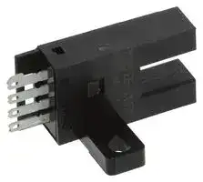


EE-SX472
PHOTOELECTRIC SENSOR
- Manufacturer: OMRON INDUSTRIAL AUTOMATION
- Product type: Optical / Slot Photoelectric Sensors
- Product Range: EE-SX67 Series
- Sensor Output: NPN
- Output Current: 100mA
- Sensing Range Max: 5mm
- Supply Voltage DC Max: 24V
- Supply Voltage DC Min: 5V
| Delivery and price | |
|---|---|
| Units per pack | 25 |
| Price | 33.4 € |
| Current stock | 50+ |
| Lead time | 7 days |
R

## EE-SX470/471/472/473/474/670/671/672/673/674(P)

Photomicrosensor with 50 mA (PNP) or 100 mA (NPN) Switching Capacity that can be Built into Equipment

- H Standard, L-shaped, T-shaped, and close mounting models available

- H Easy to maintain, plugs into Connector cordset EE-1006

- H Models available with Light-ON or Light-ON/Dark-ON output configurations

- H Response frequency as high as 1 kHz

- H Easy operation monitoring with bright LED indicator

- H Wide operating voltage range (5 to 24 VDC) makes smooth connection of the photomicrosensor with TTLs, relays, and programmable controllers (PLC) possible

## Ordering Information

Appearance Sensing method Slot width Slot depth Output configuration Weight **Part number** ~~ee~~ Standard Slot ~~es en~~ 5 mm ~~nn~~ 9 mm Li **g** ht-ON ~~GO~~ A **pp** rox. ~~PO~~ **EE-SX470** 3.1 **g EE-SX470P** Li **g** ht-ON **/** Dark-ON **EE-SX670 (S** ee no e **t ) EE-SX670P** L-sha **p** ed Li **g** ht-ON A **pp** rox. **EE-SX471** 3.0 **g EE-SX471P** Li **g** ht-ON **/** Dark-ON **EE-SX671 (S** ee no e **t )** do ~~PO~~ **EE-SX671P** ~~he =~~ T-sha **p** ed Li **g** ht-ON A **pp** rox. **EE-SX472** 2.4 **g EE-SX472P** ~~OS FT t™~‘“SOSOCOTTTTTC‘(’~~ Li **g** ht-ON **/** Dark-ON **EE-SX672** & **(S** ee no e **t ) EE-SX672P** ~~ee —_|~~ ~~**PO**~~ Close-mountin **g** Li **g** ht-ON A **pp** rox. **EE-SX473** 2.3 **g EE-SX473P** ~~a PO~~ Li **g** ht-ON **/** Dark-ON **EE-SX673 (S** ee no e **t )** 7h ~~po~~ **EE-SX673P** Close-mountin **g** Li **g** ht-ON A **pp** rox. **EE-SX474** 3.0 g **EE-SX474P** Li **g** ht-ON/Dark-ON **EE-SX674 EE-SX674P** ~~yy |—~~ - ~~ee~~

Note: The EE-SX67j series models can be used as Light-ON models when the L terminal and positive (+) terminal are short-circuited. To use them as Dark-ON models do not short-circuit these terminals. Connector EE-1001-1 can be used for Light-ON operation.

**EE-SX470/471/472/473/474/670/671/672/673/674(P)**

**EE-SX470/471/472/473/474/670/671/672/673/674(P)**

## J **ACCESSORIES**

|J **ACCESSORIES**||
|---|---|
|Name|**Part number**|
|Solder connector|**EE-1001**|
|Connector with 2 m cable|**EE-1006**|
|Connector holder for EE-1006|**EE-1006A**|


## Specifications

## J **RATINGS**

|J **RATINGS**|J **RATINGS**||||||
|---|---|---|---|---|---|---|
|Item|||Standard|L-shaped|T-shaped|Close-mounting|
|Output type||NPN<br>output|EE-SX470<br>EE-SX670|EE-SX471<br>EE-SX671|EE-SX472<br>EE-SX672|EE-SX473, EE-SX474<br>EE-SX673, EE-SX674|
|||PNP<br>output|EE-SX470P<br>EE-SX670P|EE-SX471P<br>EE-SX671P|EE-SX472P<br>EE-SX672P|EE-SX473P, EE-SX474P<br>EE-SX673P, EE-SX474P|
|Supply voltage|||5 to 24 VDC±10%, ripple (p-p): 10% max.||||
|Current consumption|||NPN models: 35 mA max., PNP models: 30 mA max.||||
|Standard reference object|||Opaque: 0.8 x 2 mm||||
|Differential distance|||0.025 mm||||
|Control output|||NPN open collector output models:<br>At 5 to 24 VDC: 100 mA load current (lc) with a residual voltage of 0.8 V max.<br>When driving TTL: 40 mA load current (lc) with a residual voltage of 0.4 V max.<br>PNP open collector output models:<br>At 5 to 24 VDC: 50 mA load current (lc) with a residual voltage of 1.3 V max.||||
|Indicator<br>**(See**n**ote**1.**)**|Without detecting<br>object||ON||||
||With detecting<br>object||OFF||||
|Response frequency (See note 2.)|||1 kHz max. (3 kHz typ.)||||
|Light source|||GaAs infrared LED with a peak wavelength of 940 nm||||
|Receiver|||Si phototransistor with a sensing wavelength of 850 nm max.||||
|Connectingmethod|||EE-1001/1006 Connectors; solderingterminals/cordset||||


- Note: 1. The indicator is GaP red LED (peak emission wavelength: 690 nm).

   2. The response frequency was measured by detecting the following disks rotating.

**==> picture [154 x 38] intentionally omitted <==**

**----- Start of picture text -----**<br>
Disk<br>2.1 mm<br>1 mm 1 mm<br>t = 0.2 mm<br>**----- End of picture text -----**<br>


2

**EE-SX470/471/472/473/474/670/671/672/673/674(P)**

**EE-SX470/471/472/473/474/670/671/672/673/674(P)**

## J **CHARACTERISTICS**

|J **CHARACTERISTICS**|J **CHARACTERISTICS**||
|---|---|---|
|Ambient illumination (See note 1.)||Fluorescent light: 1,000 ℓx max.|
|Ambient tem**p**erature|Operating|-25°C to 55°C(-13°F to 131°F)|
||Storage|-30°C to 80°C(-22°F to 176°F)|
|Ambient humidit**y**|Operating|5% to 85%|
||Storage|5% to 95%|
|Vibration resistance||Destruction: 20 to 2,000 Hz, (with a peak acceleration of 10 G), 1.5-mm double<br>amplitude for 2 hrs (with 4-minute cycles) each in X, Y, and Z directions|
|Shock resistance||Destruction: 500 m/s2 (approx. 50G) for 3 times each in X, Y, and Z directions|
|Soldering heat resistance (See note 2.)||260°±5°C when the portion between the tip of the terminals and the position<br>1.5 mm from the terminal base is dipped into the solder for 10±1 seconds|
|Degree of protection||IEC 60529, IP50|
|Materials|Case|Polybutylene teraphthalate (PBT)|
||Cover|Polycarbonate (PC)|
||Emitter/Receiver|Polycarbonate (PC)|


- Note: 1. The ambient luminance is measured on the surface of the receiver.

   2. This conforms to MIL-STD-750-2031-1.

## Engineering Data

## J **SENSING POSITION CHARACTERISTICS (TYPICAL)**

**==> picture [127 x 119] intentionally omitted <==**

**----- Start of picture text -----**<br>
Tr Dark-ON mode<br>ON<br>d<br>Q 1.0 2.0 3.0 4.0 5.0 60<br>Tr<br>OFF Distance d (mm)<br>**----- End of picture text -----**<br>


**==> picture [123 x 118] intentionally omitted <==**

**----- Start of picture text -----**<br>
Tr Dark-ON mode<br>ON<br>d<br>|<br>0 1.0 20 3.0 4.0 5.0 6.0<br>Tr<br>OFF Distance d (mm)<br>**----- End of picture text -----**<br>


## J **REPEATED SENSING POSITION CHARACTERISTICS (TYPICAL)**

**==> picture [112 x 110] intentionally omitted <==**

**----- Start of picture text -----**<br>
24<br>ine<br>ohaae<br>ON HL|<br>Ta=—25C| Ta=55C : Ta=25C<br>|<br>|<br>0 3.00 3.02 3.04<br>Distance d (mm)<br>Output level transistor<br>**----- End of picture text -----**<br>


No. of repetitions: 20 at Vcc = 12 V nd1 = 0.002 mm nd2 = 0.004 mm nd3 = 0.005 mm nd4 = 0.02 mm nd5 = 0.04 mm

3

**EE-SX470/471/472/473/474/670/671/672/673/674(P)**

**EE-SX470/471/472/473/474/670/671/672/673/674(P)**

## Operation

|Output<br>configuration<br>|Model<br>|Output<br>transistor<br>operation<br>|Timing charts<br>Wh til L d<br>||t iitd|Output circ|Output circ|uit||||
|---|---|---|---|---|---|---|---|---|---|---|---|
|NPN output<br>|EE-SX670<br>EE-SX671<br>EE-SX672<br>EE-SX673<br>EE-SX674<br>EE-SX470<br>EE-SX471|Light-ON|Incident<br>Interrupted<br>ON<br>OFF<br>Operation<br>indicator (red)<br>ON<br>OFF<br>Output<br>transistor<br>Operates<br>Releases<br>Load 1 (relay)<br><br>Ld 2<br>(en ermnas  an<br>a|re s|or crcue|Operation<br>indicator<br>(red)<br>~~Load 1~~<br>(relay)<br>Main<br>**circuit**<br>~~OUT~~<br>5 to 24 VDC<br>~~L~~<br>Q<br>IC<br>RL<br>(See Note.)<br>Load 2<br>0 V<br>Note: When using a voltage output, always<br>insert a resistor in RL.<br><br>5 to 24 VDC|Operatio<br>indicator<br>(red)|n<br>||~~L~~||
|||||||||||||
|||||||||||||
|||||||||||||
|||||||||||||
|||Dark-ON<br>Light-ON|H<br>L<br>oa<br>Incident<br>Interrupted<br>ON<br>OFF<br>Operation<br>indicator (red)<br>ON<br>OFF<br>Output<br>transistor<br>Operates<br>Releases<br>Load 1 (relay)<br>H<br>L<br>Load 2<br>Incident<br>Interrupted|||||||||
|||||||||||||
|||||||||||||
|||||||||||||
|||||||||||||
|||||||||||||
|||||||||||||
|||||||||||||
|||||||||||||
||EE-SX472<br>EE-SX473<br>EE-SX474<br>||ON<br>OFF<br>Operation<br>indicator (red)<br>ON<br>OFF<br>Output<br>transistor<br>Operates<br>Releases<br>Load 1 (relay)<br>H<br>L<br>Load 2<br> <br>|||Operation<br>indicator<br>(red)<br>Load 1<br>(relay)<br>Main<br>circuit<br>Load 2<br>OUT<br>0 V<br>Q<br>IC<br>Note: When using a voltage output, always<br>insert a resistor in RL.<br>RL<br>(See Note.)||||||
|PNP output|EE-SX670P<br>EE-SX671P<br>EE-SX672P<br>EE-SX673P<br>EE-SX674P<br>EE-SX470P<br>EE-SX471P<br>EE-SX472P<br>EE-SX473P|Light-ON<br>Dark-ON|Incident<br>Interrupted<br>ON<br>OFF<br>Operation<br>indicator (red)<br>ON<br>OFF<br>Output<br>transistor<br>Operates<br>Releases<br>Load (relay)<br>H<br>L<br>Voltage output<br>(When terminals L and<br>a<br>Incident|re s|ort circuited)|Operati<br>indicato<br>(red)<br><br><br>Note: Wh<br>ins<br>Operati<br>indicato<br>(red)||on<br>r||||
|||||||||||||
|||||||||||||
|||||||||Main<br>circuit||||
|||||||||||||
|||Light-ON|Interrupted<br>ON<br>OFF<br>Operation<br>indicator (red)<br>ON<br>OFF<br>Output<br>transistor<br>Operates<br>Releases<br>Load 1 (relay)<br>H<br>L<br>Load 2<br>Incident<br>Interrupted<br>ON<br>OFF<br>Operation<br>indicator (red)<br>|||||||||
|||||||||||||
|||||||||||||
|||||||||||||
|||||||||||||
|||||||||||||
|||||||||||||
|||||||||||||
|||||||||||||
||EE-SX474P||ON<br>OFF<br>Output<br>transistor<br>Operates<br>Releases<br>Load (relay)<br>H<br>L<br>Voltage output|||Note: Wh<br>ins||Main<br>circuit||||
|||||||||||||


4

**EE-SX470/471/472/473/474/670/671/672/673/674(P)**

**EE-SX470/471/472/473/474/670/671/672/673/674(P)**

## Dimensions

Unit: mm (inch)

## J **EE-SX470(P), EE-SX670(P)**

**==> picture [370 x 206] intentionally omitted <==**

**----- Start of picture text -----**<br>
25.4<br>(1.00)<br>19<br>(0.75)<br>Two, 3.2 dia. holes<br>6.95<br>(0.27)<br>Four, R1<br>19 6.4<br>13.4 (0.75) (0.25)<br>(0.53)5 0.8(0.03)<br>(0.20)<br>(0.35)9 Opticalaxis To — (0.08)2 Terminal Arrangement<br>13.8 a (1) VCC<br>(0.54) (2) L L (See Note.)<br>(0.52)13.2 ff) (3) OUT OUTPUT<br>5.5(0.22) (4) GND (0 V)<br>Two, 3.8 dia.<br>6.2 3.8 pete holes |} Ee<br>(0.24) (0.15) Indicator window<br>(1) (2) (3)(4) 0.3 0.7<br>jk (0.10)2.54 (0.01) (0.03)<br>**----- End of picture text -----**<br>


Note: L Terminal needs no connection for all EE-SX47j series sensors.

## J **EE-SX471(P), EE-SX671(P)**

**==> picture [369 x 228] intentionally omitted <==**

**----- Start of picture text -----**<br>
26.2<br>(1.03)<br>19.0<br>(0.75) Four, R2<br>3.2(0.13)<br>14.5 eet} - foley Terminal Arrangement<br>(0.57) Four, R1.0<br>re (1) —— V CC<br>3.0(0.12)<br>3.8 Indicator window (2) L L (See Note.)<br>(0.24)6.2 (0.15) (3) OUT OUTPUT<br>(1) (2) (3)(4) (4) GND (0 V)<br>(0.10)2.54 AL 13.0 6.35<br>13.4 (0.51) (0.25)<br>(0.53)5.0 0.8<br>(0.20) (0.03) 2(0.08)<br>8.3 Optical axis<br>(0.35)9.0 (0.33) (0.35)9.0 a Two, 3.2 dia. holes2.1(0.08) 0.3(0.01) cs 15.5<br>(0.61)<br>7.2 TT 6.20 , 7.2<br>(0.28) (0.24) (0.28)<br>Ee] EES<br>13.0 6.95<br>(0.14)3.6 (0.51)13.4 _ (0.03)0.7 (0.02)0.6 (0.27)<br>(0.53) 19.0<br>(0.75)<br>**----- End of picture text -----**<br>


Note: L Terminal needs no connection for all EE-SX47j series sensors.

5

~~OMRON~~ **EE-SX470/471/472/473/474/670/671/672/673/674(P) EE-SX470/471/472/473/474/670/671/672/673/674(P)**

## J **EE-SX472(P), EE-SX672(P)**

**==> picture [392 x 281] intentionally omitted <==**

**----- Start of picture text -----**<br>
13.7<br>(0.54)<br>3.0<br>(0.12) Terminal Arrangement<br>26.0 (1) V CC<br>( 1.02 ) 6.4 (2) L L (See Note.)<br>(0.25)<br>12.6 (3) OUT OUTPUT<br>( 0.50 )<br>(4) GND (0 V)<br>0.8<br>13.4 (0.03)<br>(0.53) 0.1 0.1<br>fe 5.0 (0.004) (0.004)<br>(0.359.0 ) (0.20) Optical axis (0.08)2 Indicator window<br>2.9 0.2 operation (back)<br>4.3<br>( 0.11 ) (0.01)<br>ASLL E HEE| (0.17) 7 F<br>22.2<br>(0.87)<br>6.2<br>(0.2 4)<br>i omRron 6.3 | | 4-R1.6 E E-SXxX6725 ||<br>( 0.2 F 5) t] | | [SY]<br>(0.24)6.2 (0.15)3.8 (0.03)0.7 0.3 4-R1.0<br>(0.01)<br>2.54<br>ree 19.0 eae<br>(0.10)<br>on 13 3 i (0.75) EAH<br>(0.51)<br>**----- End of picture text -----**<br>


Note: L Terminal needs no connection for all EE-SX47j series sensors.

## J **EE-SX473(P), EE-SX673(P)**

**==> picture [376 x 217] intentionally omitted <==**

**----- Start of picture text -----**<br>
6.3<br>(0.25)<br>12.8<br>(0.50) 6.65<br>3.5(0.14) (0.26)<br>Two, 3.2 dia. holes<br>7 Terminal Arrangement<br>Be Two, R1<br>(0.28)<br>13.4 (1) VCC<br>(0.53) , (2) L L (See Note.)<br>5 0.8<br>(0.20) (0.03) (3) OUT OUTPUT<br>9 Optical axis (0.08)2 (4) GND (0 V)<br>(0.35)<br>14.4<br>22.2 (0.57)<br>(0.87)<br>2.8(0.11)<br>4.9(0.19)<br>3.8 = Indicator window<br>6.2 (0.15)<br>(0.24)<br>(1) (2)(3)(4) 0.3 0.7<br>aon (0.10)2.54 (0.01) (0.03)<br>**----- End of picture text -----**<br>


Note: L Terminal needs no connection for all EE-SX47j series sensors.

6

~~romeo~~ **EE-SX470/471/472/473/474/670/671/672/673/674(P) EE-SX470/471/472/473/474/670/671/672/673/674(P)**

## J **EE-SX474(P), EE-SX674(P)**

**==> picture [279 x 243] intentionally omitted <==**

**----- Start of picture text -----**<br>
2--R1 7 Two 3.5 dia holes<br>(0.28) Light Indicator<br>7<br>(0.28)<br>es<br>21.5<br>(0.85)<br>3<br>(0.12)<br>3.8<br>6.2 (0.15)<br>(0.24)<br>= EEE<br>1 2 3 4<br>2.54<br>(0.10)<br>13.0 0.8 0.1<br>(0.51) (0.03) (0.004)<br>Optical Axis Mark<br>5 2.2<br>(0.20) (0.09)<br>2.9(0.11)<br>roe 9.3 Optical Axis = 3<br>(0.37) 2.1 0.3 15.5<br>(0.08) (0.01) (0.61)<br>6.2<br>(0.24) 0.7 2.6(0.10)<br>(0.03)<br>13.6<br>rr 0.6 — +<br>(0.54)<br>(0.02)<br>**----- End of picture text -----**<br>


**==> picture [116 x 70] intentionally omitted <==**

**----- Start of picture text -----**<br>
Terminal Arrangement<br>(1) VCC<br>(2) L L (See Note.)<br>(3) OUT OUTPUT<br>(4) GND (0 V)<br>Lbs +<br>**----- End of picture text -----**<br>


Note: L Terminal needs no connection for all EE-SX47j series sensors.

## J **EE-1001 SOLDER CONNECTOR**

## J **EE-SX67** j **(P) WITH EE-1001 CONNECTOR**

**==> picture [281 x 135] intentionally omitted <==**

**----- Start of picture text -----**<br>
13.0<br>(0.51)<br>2.54±0.15<br>4.0<br>(0.16) 0.6 22.2<br>(0.02) (0.87)<br>10.8<br>10.8 (0.43)<br>(0.43) 6.0<br>_ (0.24)<br>6.0<br>(0.24)<br>Ju<br>2.9±1<br>**----- End of picture text -----**<br>


## J **EE-1006 CONNECTOR WITH CABLE**

**==> picture [237 x 69] intentionally omitted <==**

**----- Start of picture text -----**<br>
0.6<br>(0.02) 16.2 20 2,000 25 15<br>(0.64) (0.79) (78.74) (0.98) (0.59)<br>2.54 (1)<br>(0.10) (2)<br>11.8 7 (3) ee<br>(0.46) (4)<br>|<br>5.3<br>(0.21)<br>**----- End of picture text -----**<br>


Terminal Arrangement -- IEC Colors

|(1)|Brown (Red)|||VCC|
|---|---|---|---|---|
|(2)|Pink(Yellow)|L||L|
|(3)|Black(White)|OUT||OUTPUT|
|Note: <br>(4)|Older standard colors are shown in<br>Blue (Black)<br>GND (O V)<br>~~|~~||||
||parentheses. Connector comes with a||||
||2-m attached cable.||||


7

**EE-SX470/471/472/473/474/670/671/672/673/674(P)** ~~So~~

**EE-SX470/471/472/473/474/670/671/672/673/674(P)**

## J **EE-1006A CONNECTOR HOLDER**

**==> picture [199 x 157] intentionally omitted <==**

**----- Start of picture text -----**<br>
25.2<br>3.2 19 (0.99) 3.6<br>(0.13) (0.75) 12 (0.14)<br>(0.47) R3 5.5<br>3.4 (0.22)<br>(0.13) Ne id Four, R2<br>10.2 2.1(0.08) i e Four,R1.6<br>(0.40)<br>3(0.12)<br>3<br>(0.12) =i 5<br>19.4<br>(0.76) 15<br>21.9<br>(0.59) 1.2<br>(0.86)<br>(0.05)<br>(R1)<br>2<br>(0.08)<br>**----- End of picture text -----**<br>


## Precautions

Refer to the the Technical Information Section for general precautions.

The sensing window is made of a polycarbonate resin which withstands chloride solvents and strong acids but is soluble in strong alkali, aromatic hydrocarbons, and aliphatic hydrocarbonate chloride solvents.

The casing material uses a PBT resin which withstands chemicals and oil but is soluble in strong acid or alkali solvents.

The temperature of the terminals at the time of soldering must not exceed the following:

|**Item**|**Temperature**|**Permissible**<br>**time**|**Remarks**|
|---|---|---|---|
|Dip|260°C|10 sec|The portion be-<br>tween the base of<br>the terminals and<br>**the** **position** **1** **5**<br>.<br>mm from the ter-<br>minal base must<br>not be soldered.|
|Iron|350°C|3 sec||


The terminal base uses a polycarbonate resin, which could be deformed by excessive soldering heat.

## ~~OO~~ **NOTE: DIMENSIONS SHOWN ARE IN MILLIMETERS. To convert millimeters to inches divide by 25.4.**

R

**OMRON ELECTRONICS LLC** One East Commerce Drive Schaumburg, IL 60173 **1-800-55-OMRON**

**OMRON ON--LINE** Global -- http://www.omron.com USA -- http://www.omron.com/oei Canada -- http://www.omron.com/oci

**OMRON CANADA, INC.** 885 Milner Avenue Toronto, Ontario M1B 5V8 **416-286-6465**

Cat. No. GC APMS-1

Specifications subject to change without notice.

8

09/02

Printed in U.S.A.
Updated at February 9, 2023
With a legacy spanning over 80 years, Omron Industrial Automation is a globally recognized leader in the manufacture of advanced industrial control and automation components. Renowned for their reliability and engineering excellence, Omron delivers comprehensive solutions that enhance efficiency, machine safety, and precision across a wide range of manufacturing environments. Our extensive portfolio of Omron products is heavily focused on their industry-leading sensing and switching technologies. We offer a vast selection of sensors, excelling specifically in high-performance proximity sensors, light sensors, and temperature sensors. Complementing this range are robust switching solutions, featuring a deep inventory of power relays, solid-state relays, safety relays, and essential relay accessories designed for demanding operational requirements. Beyond sensing and switching, Omron is highly regarded for its precision automation and process control equipment. Our selection features highly accurate temperature controllers, versatile process controllers, and sophisticated panel displays and instrumentation. To support these fundamental systems, we also supply dependable Omron power supplies, notably AC/DC converters, alongside vital connectivity components like DIN rail terminal blocks to ensure secure, efficient, and complete industrial setups.
About Novapart
Novapart is a B2B electronic component broker specialising in stock shortages and cost reduction. We source hard-to-find parts and identify compliant alternatives across a catalogue of 410,000+ components from 500+ manufacturers.
Learn more →Stock Shortage Specialist
When a component is unavailable, discontinued or has an unacceptable lead time, we tap into our network of vetted European and Asian distributors to source what you need — without compromising on quality or traceability.
Request a quote →Compliant Alternatives
We identify pin-to-pin, electrically equivalent substitutes that meet the same certifications (RoHS, AEC-Q100, REACH) as your original specification — validated against datasheets, not just part numbers. Often at a lower cost.
BOM Analysis service →