


ECM60US24..
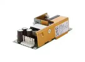
AC/DC Open Frame Power Supply (PSU), ITE & Medical, 1 Output, 60 W, 90V AC to 264V AC, Fixed
- Manufacturer: XP POWER
- Product type: AC / DC Open Frame Power Supplies
- No. of Outputs:1 Output; Power Rating (Covection Cooling):60W; Power Rating (Forced Cooling):-; Input Voltage VAC:90V AC to 264V AC; Power Supply Output Type:Fixed; Output Voltage
- SVHC: No SVHC (16-Jul-2019)
- Product Range: ECM60 Series
- No. of Outputs: 1 Output
- Output Power Max: 60W
- Input Voltage VAC: 90V AC to 264V AC
- Input Voltage AC Max: 264V
- Input Voltage AC Min: 90V
- Power Supply Output Type: Fixed
- Output Current - Output 1: 2.5A
- Output Current - Output 2: -
- Output Current - Output 3: -
- Output Current - Output 4: -
- Output Voltage - Output 1: 24VDC
- Output Voltage - Output 2: -
- Output Voltage - Output 3: -
- Output Voltage - Output 4: -
- Power Supply Applications: ITE & Medical
- Power Rating (Forced Cooling): -
- Power Rating (Convection Cooling): 60W
| Delivery and price | |
|---|---|
| Units per pack | 50 |
| Price | 49.83 € |
| Current stock | 500+ |
| Lead time | 30 days |
- 40 & 60 Watt Models

- Small Size 2.0”x 4.0”x 1.2”

- Low Leakage Current

- Industrial & Medical Approvals

- Full Load Available Convection Cooled

- Wide Operating Temperature 0 °C to +70 °C

- Level B Conducted Emissions

- EN61000 Compliant

- Universal AC Input 90-264 VAC

- Input Frequency 47-63 & 440 Hz

- Single & Multiple Outputs

- Cover Kits Available

- Mating Connector & Loom Kits Available

Approved for Class I and Class II applications, the ECM range of single and multiple output AC-DC, 40-60 W power supplies from XP feature the world's smallest footprint for units of these ratings. Both are just 2" x 4" (50.8 mm x 101.6 mm) and 1.2" (30.48 mm) high. Furthermore, these high-density power supplies meet EN55032 Level B conducted emissions with maximum leakage currents of 100 µA at 115 VAC or 200 µA at 230 VAC. As a result, these switchers are equally suitable for industrial, IT and medical applications, with no price premium for meeting medical requirements.

The ECM40-60 series have single output versions from 5 V to 48 VDC, adjustable by ±10%, and dual and triple output versions covering combinations of 3.3 V, 5 V, 12 V, 15 V and 24 V. They are dual-fused for compliance with IEC60601-1 and efficiency is 80-85%, depending upon the model, so minimal excess heat is generated.

The power supplies deliver full power between 0 °C and +50 °C and will operate at up to +70 °C with derating and only 5 CFM of cooling. Comprehensive overvoltage, overload and short circuit protection is built in. Covers, looms and connector kits are available.

xppower.com

## Input Characteristics

|Characteristic|Characteristic|Minimum|Typical|Maximum|Units|Notes & Conditions|
|---|---|---|---|---|---|---|
|Input Voltage - Operating<br>~~GG~~||90<br>~~GG~~|~~GG ~~|264<br> ~~GG~~|VAC<br>~~GG~~|120-370 VDC<br>~~GG~~|
|Input Frequency<br>~~pT~~||47<br>~~pT~~|50/60<br>~~pT~~|63<br>~~pT~~|Hz<br>~~pT~~|400 Hz operation available<br>~~pT~~|
|Input Current - No load<br>~~pT~~||~~pT~~|~~pT~~|41<br>~~pT~~|mA<br>~~pT~~|230 VAC<br>~~pT~~|
|Input Current - Full load<br>~~pT~~<br>~~pT~~||~~pT~~<br>~~pT~~|~~pT~~<br>~~pT~~|1.38<br>~~pT~~<br>~~pT~~|A<br>~~pT~~<br>~~pT~~|90 VAC<br>~~pT~~<br>~~pT~~|
|Inrush Current<br>~~a~~||~~GG~~|~~GG ~~|40<br> ~~OC~~|A<br>~~OC~~|Cold start at 230 VAC<br>~~OC~~|
|Power Factor<br>~~pT~~||~~pT~~|0.62<br>~~pT~~|~~pT~~|~~pT~~|230 VAC<br>~~pT~~|
|Earth Leakage Current<br>~~pT~~||~~pT~~|~~pT~~|290<br>~~pT~~|µA<br>~~pT~~|264 VAC<br>~~pT~~|
|Input Protection<br>~~pT~~||~~pT~~|~~pT~~|~~pT~~|~~pT~~|T3.15 A/ 250 V internal fuse in line & neutral<br>~~pT~~|


All specifications are at nominal input, full resistance load at 25°C unless otherwise stated.

## Output Characteristics

|Characteristic<br>~~Le~~|Minimum<br>~~GG~~|Typical<br>~~GG~~|Maximum<br>~~GG~~|Units|Notes & Conditions|
|---|---|---|---|---|---|
|Output Voltage<br>~~Le~~<br>~~po~~|5.0<br>~~GG~~|~~GG~~|48.0<br>~~GG~~|VDC|See modules table|
|Initial Set Accuracy<br>~~Le ~~<br>~~po~~|~~GG~~|~~GG~~|V1: ±1,V2& V3: ±5<br>~~GG~~|%||
|Output Voltage Trim<br>~~po~~<br>~~GG~~|±10<br>~~GG~~|~~GG~~|~~GG~~|%<br>~~GG~~|V1 (V2will track V1bythe same %)<br>~~GG~~|
|Minimum load<br>~~pT~~|V1: 0.5,V2: 0.1<br>~~pT~~|~~pT~~|~~pT~~|A<br>~~pT~~|Not required on single output models<br>~~pT~~|
|Start UpDelay<br>~~po~~|~~po~~|~~po~~|1.5<br>~~po~~|s<br>~~po~~|90 VAC<br>~~po~~|
|Start UpRise Time<br>~~pp~~|~~pp~~|~~pp~~|10<br>~~pp~~|ms<br>~~pp~~|~~pp~~|
|Hold UpTime<br>~~po~~<br>~~po~~|16<br>~~po~~|~~po~~|75<br>~~po~~|ms<br>~~po~~|115-230 VAC input<br>~~po~~|
|Drift<br>~~po~~<br>~~po~~|||±0.2|%||
|Line Regulation<br>~~po~~<br>~~po~~<br>~~po~~|||±0.5|%|90-264 VAC|
|Load Regulation<br>~~po~~<br>~~po~~<br>~~po~~|||±1.0|%|Single output|
|~~po~~<br>~~po~~|||V1: ±3,V2& V3: ±5|%|Dual output|
|Transient Response<br>~~po~~<br>~~po~~|||4|%|Output voltage recovers to within 1% in less<br>than 500µs for 50% load change.|
|Ripple & Noise<br>~~po~~<br>~~po~~|||1|%pk-pk|20 MHz bandwidth|
|Overvoltage Protection<br>~~po~~<br>~~po~~<br>~~po~~|115||135|VDC|Recycle input to reset|
|Overload Protection<br>~~po~~<br>~~po~~|110||170|% Imax|Auto-recovery|
|Short Circuit Protection<br>~~po~~<br>~~a~~<br>~~Le~~|~~GO~~<br>~~GO~~|~~GO~~<br>~~GO~~|~~GO~~<br>~~GO~~||Trip& restart(hiccupmode)|
|Temperature Coefficient<br>~~Le~~|~~GO~~|~~GO~~|0.05<br>~~GO~~|%/ºC||


## General Specifications

|Characteristic<br>~~pO~~|Minimum<br>~~pO~~|Typical<br>~~pO~~|Maximum<br>~~pO~~|Units|Notes & Conditions<br>~~pT~~|
|---|---|---|---|---|---|
|Efficiency<br>~~pO~~<br>~~pO~~|70<br>~~pO~~<br>~~ee~~|~~pO~~<br>~~ee~~|~~pO~~|%<br>(at 230 VAC<br>full load)|3.3 & 5 V single output versions<br>~~pT~~<br>~~pO~~|
||80<br>~~pO~~<br>~~ee~~<br>~~ee~~|~~pO~~<br>~~ee~~<br>~~ee~~|~~pO~~||All other single output versions<br>~~pT~~<br>~~pO~~<br>~~pT~~|
||75<br>~~ee~~<br>~~ee~~<br>~~pO~~|~~ee~~<br>~~ee~~<br>~~pO~~|~~pO~~||Dual output versions<br>~~pO~~<br>~~pT~~<br>~~pO~~|
|Isolation Voltage<br>~~pO~~<br>~~po~~|~~ee~~<br>~~pO~~<br>~~po~~|4000<br>~~ee~~<br>~~pO~~<br>~~po~~|~~pO~~<br>~~po~~|VAC|Input to output<br>~~pT~~<br>~~pO~~<br>~~pO~~|
||~~pO~~<br>~~po~~<br>~~ee~~|1500<br>~~pO~~<br>~~po~~<br>~~ee~~|~~pO~~<br>~~po~~||Input toground<br>~~pO~~<br>~~pO~~<br>~~pO~~|
||~~po~~<br>~~ee~~|500<br>~~po~~<br>~~ee~~|~~po~~||Output toground<br>~~pO~~<br>~~pO~~|
|SwitchingFrequency<br>~~DG~~|~~ee~~<br>~~DG ~~|70<br>~~ee~~<br> ~~GG~~|~~GG~~|kHz<br>~~GG~~|Fixed<br>~~pO~~|
|Power Density<br>~~LG~~|~~LG ~~|~~GO~~|6.25<br>~~GO~~|W/In3<br>~~GO~~|For 60 W version|
|Weight<br>~~LG~~<br>~~po~~|~~LG ~~|0.33(150)<br> ~~GO~~|~~GO~~|lbs(g)<br>~~GO~~||
|MTBF<br>~~po~~||600||kHrs|Mil HDBK 217F|


2

xppower.com

## Environmental

|Characteristic|Minimum|Typical|Maximum|Units|Notes & Conditions|
|---|---|---|---|---|---|
|OperatingTemperature|-0||+70|ºC|See deratingcurves|
|Storage Temperature|-40||+85|ºC||
|Cooling||0||CFM|Convection-cooled|
|OperatingHumidity|||95|% RH|Non- condensing|
|OperatingAltitude|||3000|m||
|Shock|||30|Gpk|Half sine 6 axis|
|Vibration|||2|G|5-500 Hz 3 axis|


## Electromagnetic Compatibility & Immunity

|Standard|Test Level|Criteria|Notes & Conditions|
|---|---|---|---|
|Emissions|EN55032|Class B Conducted||
||EN55032|Class A Radiated<br>~~on~~|~~on~~|
||EN60601-1-2|Class B Conducted<br>~~on~~|~~on~~|
|Harmonic Currents|EN61000-3-2|~~on~~|~~on~~|
|Voltage Flicker|EN61000-3-3|~~on~~|~~on~~|
|ESD Immunity|EN61000-4-2|level 2, performance criteria A<br>~~on~~|~~on~~|
|Radiated Immunity|EN61000-4-3|10 V/m, performance criteria A<br>~~on~~|~~on~~|
|EFT/Burst<br>~~—————~~|EN61000-4-4<br>~~—————~~|level 2, performance criteria A<br>~~on~~<br>~~—————~~|~~on~~<br>~~—————~~|
|Surge<br>~~—————~~|EN61000-4-5<br>~~—————~~|level 3, performance criteria A<br>~~on~~<br>~~—————~~|~~on~~<br>~~—————~~|
|Conducted Immunity<br>~~—————~~|EN61000-4-6<br>~~—————~~|10 Vrms, performance criteria A<br>~~on~~<br>~~—————~~|~~on~~<br>~~—————~~|
|Dips & Interruptions<br>~~—————~~|EN61000-4-11<br>~~—————~~|70% UT:performance criteria A<br>~~on~~<br>~~—————~~|For 10 ms, 100% load<br>~~on~~<br>~~—————~~|
|||40% UT:performance criteria B<br>~~on~~<br>~~—————~~|For 100 ms,100% load<br>~~on~~<br>~~—————~~|
|||0% UT:performance criteria B<br>~~on~~<br>~~—————~~<br>~~————~~|For 5000 ms,100% load<br>~~on~~<br>~~—————~~|
|Dips & Interruptions|EN61000-4-11<br>(Medical)|70% Ut, performance criteria A<br>~~on~~<br>~~————~~|For 500 ms,Medical,100% load<br>~~on~~|
|||40% Ut, performance criteria A<br>~~————~~|For 100 ms,Medical,60% load|
|||0% Ut, performance criteria A<br>~~————~~|For 10 ms,Medical,100% load|
|||0% Ut, performance criteria B<br>~~————~~|For 5000 ms, Medical, 100% load|


## Safety Approvals

||SafetyAgency|SafetyStandard|Category|
|---|---|---|---|
||CB Report|IEC60950-1:2005 Ed 2 / IEC62368-1:2014<br>Certificate #US/18293 & 18269/UL,IEC60601-1 Ed 3 IncludingRisk Management|Information Technology<br>Medical|
||UL|UL 62368-1 & CAN/CSA C22.2 No. 62368-1-14|Information Technology|
|||UL File # E146893,ANSI/AAMI ES 60601-1:2005 & CSA C22.2 No. 60601-1:08|Medical|
||EN|EN62368-1:2014/A11:2017|Information Technology|
|||TUV Certificate # B12 01 57396 125,EN60601-1:2006|Medical|
||CE|Meets all applicable directives||
||UKCA|Meets all applicable legislation||
|||||
|Equipment Protection<br>Class<br>Safety Standard<br>Notes & Conditions<br>Class I & Class II<br>IEC60950-1:2005 Ed 2 / IEC62368-1:2014<br>See safety agency conditions of<br>acceptability for details<br>Means of Protection<br>Category<br>Primaryto Secondary<br>1 x MOPP(Means of Patient Protection)Contact Sales for 2 x MOPP<br>IEC60601-1 Ed 3<br>Primary to Earth<br>1 x MOPP (Means of Patient Protection)<br>~~————————————~~<br>~~pC~~||||


3

~~2~~ xppower.com

## Models & Ratings

|Max<br>Power<br>~~po~~|Outputs|Outputs|Outputs|Outputs|Outputs|Outputs|Model<br>Number|
|---|---|---|---|---|---|---|---|
||V1<br>~~po~~|Imin/Imax(3)<br>~~po~~|V2|Imin/Imax|V3|Imin/Imax||
|40 W<br>~~po~~<br>~~apf~~<br>~~po~~<br>~~po~~<br>~~po~~<br>~~apf~~<br>~~pf~~<br>~~po~~<br>~~pO~~<br>~~eG~~<br>~~pf~~<br>~~pO~~<br>~~sO~~<br>~~Pp~~|5.0 V<br>~~po~~|0.0 A / 8.0 A<br>~~po~~|||||ECM40US05|
||7.0 V<br>~~po~~<br>~~a~~|0.0 A / 5.7 A<br>~~po~~<br>|||||ECM40US07<br>|
||9.0 V<br>~~apf~~|0.0 A / 4.4 A<br>~~pf~~|~~pf~~|~~pf~~|~~pf~~|~~pf~~|ECM40US09<br>~~pf~~|
||12.0 V<br>~~po~~|0.0 A / 3.5 A<br>~~po~~|~~po~~|~~po~~|~~po~~|~~po~~|ECM40US12<br>~~po~~|
||15.0 V<br>~~po~~|0.0 A / 2.7 A<br>~~po~~|~~po~~|~~po~~|~~po~~|~~po~~|ECM40US15<br>~~po~~|
||18.0 V<br>~~po~~|0.0 A / 2.2 A<br>~~po~~|~~po~~|~~po~~|~~po~~|~~po~~|ECM40US18<br>~~po~~|
||24.0 V<br>~~a~~|0.0 A / 1.7 A<br>|||||ECM40US24<br>|
||33.0 V<br>~~apf~~|0.0 A / 1.2 A<br>~~pf~~|~~pf~~|~~pf~~|~~pf~~|~~pf~~|ECM40US33<br>~~pf~~|
||48.0 V<br>~~pf~~<br>~~po~~|0.0 A / 0.9 A<br>~~pf~~|~~pf~~|~~pf~~|~~pf~~|~~pf~~|ECM40US48<br>~~pf~~|
||+5.0 V<br>~~po~~<br>~~pO~~|0.5 A / 6.0 A|+12.0 V|0.1 A / 2.0 A|||ECM40UD21|
||+5.0 V<br>~~po~~<br>~~pO~~|0.5 A / 6.0 A|+15.0 V|0.1 A / 1.5 A|~~GO~~|~~GO~~|ECM40UD22|
||+5.0 V<br>~~pO~~<br>~~eG~~|0.5 A / 6.0 A<br>~~eG~~|+12.0 V<br>~~eG~~|0.1 A / 2.0 A<br>~~eG~~|-12.0 V<br>~~eG~~<br>~~GO~~|0.0 A / 0.5 A<br>~~eG~~<br>~~GO~~|ECM40UT31<br>~~eG~~|
||+5.0 V<br>~~pf~~|0.5 A / 6.0 A<br>~~pf~~|+24.0 V<br>~~pf~~|0.1 A / 1.0 A<br>~~pf~~|-12.0 V<br>~~GO~~<br>~~pf~~|0.0 A / 0.5 A<br>~~GO~~<br>~~pf~~|ECM40UT32<br>~~pf~~|
||+5.0 V<br>~~pO~~<br>~~Pp~~|0.5 A / 6.0 A<br>~~pO~~|+15.0 V<br>~~pO~~|0.1 A / 1.5 A<br>~~pO~~|-15.0 V<br>~~pO~~<br>~~GO~~|0.0 A / 0.5 A<br>~~pO~~<br>~~GO~~|ECM40UT33<br>~~pO~~|
||+3.3 V<br>~~sO~~<br>~~Pp~~|0.5 A / 6.0 A<br>~~sO~~|+5.0 V<br>~~sO~~|0.1 A / 1.5 A<br>~~sO~~|+12.0 V<br>~~sO~~<br>~~GO~~|0.0 A / 0.5 A<br>~~sO~~<br>~~GO~~|ECM40UT34<br>~~sO~~|
||+5.0 V<br>~~Pp~~|0.5 A / 6.0 A|+3.3 V|0.1 A / 1.5 A|+12.0 V<br>~~GO~~|0.0 A / 0.5 A<br>~~GO~~|ECM40UT35|


|Max<br>Power|Outputs|Outputs|Outputs|Outputs|Outputs|Outputs|Model<br>Number<br>|
|---|---|---|---|---|---|---|---|
||V1<br>~~a~~|Imin/Imax(3)<br>~~eG~~|V2<br>~~eG~~|Imin/Imax<br>|V3<br>|Imin/Imax<br>||
|60 W|5.0 V<br>~~a~~|0.0 A / 12.00 A<br>~~eG~~|~~eG(nC~~|~~(nC~~|~~(nC~~|~~(nC~~|ECM60US05<br>~~(nC~~|
||7.0 V<br>~~a~~<br>~~po~~|0.0 A / 8.60 A<br>~~eG~~<br>~~po~~|~~eG~~<br>~~po~~|~~po~~|~~po~~|~~po~~|ECM60US07<br><br>~~po~~|
||9.0 V<br>~~Ge~~|0.0 A / 6.70 A<br>~~Ge~~|~~Ge~~|~~(CR~~|~~(CR~~|~~(CR~~|ECM60US09<br>~~(CR~~|
||12.0 V<br>~~po~~|0.0 A / 5.00 A<br>~~po~~|~~po~~|~~po~~|~~po~~|~~po~~|ECM60US12<br>~~po~~|
||15.0 V<br>~~po~~|0.0 A / 4.00 A<br>~~po~~|~~po~~|~~po~~|~~po~~|~~po~~|ECM60US15<br>~~po~~|
||18.0 V<br>~~(O(N~~|0.0 A / 3.30 A<br>~~(O(N~~|~~(O(N~~|~~(O(N~~|~~(O(N~~|~~(O(N~~|ECM60US18<br>~~(O(N~~|
||20.0 V<br>~~pO~~|0.0 A / 3.00 A<br>~~pO~~|~~pO~~|~~pO~~|~~pO~~|~~pO~~|ECM60US20<br>~~pO~~|
||24.0 V<br>~~po~~|0.0 A / 2.50 A<br>~~po~~|~~po~~|~~po~~|~~po~~|~~po~~|ECM60US24<br>~~po~~|
||28.0 V<br>~~po~~|0.0 A / 2.14 A<br>~~po~~|~~po~~|~~po~~|~~po~~|~~po~~|ECM60US28<br>~~po~~|
||33.0 V<br>~~po~~|0.0 A / 1.80 A<br>~~po~~|~~po~~|~~po~~|~~po~~|~~po~~|ECM60US33<br>~~po~~|
||48.0 V<br>~~C(O~~|0.0 A / 1.25 A<br>~~C(O~~|~~C(O~~|~~C(O~~|~~C(O~~|~~C(O~~<br>~~(~~|ECM60US48<br>~~C(O~~|
||+5.0 V<br>~~DC~~|0.5 A / 8.00 A<br>~~DC~~|+12.0 V<br>~~DC~~|0.1 A / 3.0 A<br>~~DC~~|~~DC~~|~~DC~~<br>~~(~~<br>~~(~~|ECM60UD21<br>~~DC~~|
||+5.0 V<br>~~SY~~|0.5 A / 8.00 A<br>~~SY~~|+15.0 V<br>~~SY~~|0.1 A / 2.5 A<br>~~SY~~|~~SY~~|~~(~~<br>~~SY~~<br>~~(~~|ECM60UD22<br>~~SY~~|
||+5.0 V<br>~~GG~~|0.5 A / 8.00 A<br>~~GG~~|+12.0 V<br>~~GG~~|0.1 A / 3.0 A<br>~~GG~~|-12.0 V<br>~~GG~~|0.0 A / 0.5 A<br>~~(~~<br>~~GG~~|ECM60UT31<br>~~GG~~|
||+5.0 V<br>~~a~~|0.5 A / 8.00 A<br>~~a ~~|+24.0 V<br> ~~GG~~|0.1 A / 1.5 A<br>~~GG~~|-12.0 V<br>~~GG~~|0.0 A / 0.5 A<br>~~GG~~|ECM60UT32<br>~~GG~~|
||+5.0 V<br>~~a~~|0.5 A / 8.00 A<br>~~a ~~|+15.0 V<br> ~~GG~~|0.1 A / 2.5 A<br>~~GG~~|-15.0 V<br>~~GG~~|0.0 A / 0.5 A<br>~~GG~~|ECM60UT33<br>~~GG~~|
||+3.3 V<br>~~GG~~|0.5 A / 8.00 A<br>~~GG~~|+5.0 V<br>~~GG~~|0.1 A / 1.5 A<br>~~GG~~|+12.0 V<br>~~GG~~|0.0 A / 0.5 A<br>~~GG~~|ECM60UT34<br>~~GG~~|
||+5.0 V<br>~~PO~~|0.5 A / 8.00 A<br>~~PO~~|+3.3 V<br>~~PO~~|0.1 A / 1.5 A<br>~~PO~~|+12.0 V<br>~~PO~~|0.0 A / 0.5 A<br>~~PO~~|ECM60UT35<br>~~PO~~|


## ~~**Notes**~~

_1. V2 will track a change in V1 by the same percentage change in voltage as V1 is trimmed._

_2. To receive unit with cover fitted, add suffix ‘-C’ to model number. For Class I operation only._

_3. A 120% peak load can be taken for up to 100 ms with a 25% duty cycle. Average load not to exceed maximum power rating._

4

xppower.com

## Thermal Derating Curves

All ECM40 models convection-cooled

All ECM40 models with 5 CFM

**==> picture [510 x 93] intentionally omitted <==**

**----- Start of picture text -----**<br>
100% 100%<br>75% 75%<br>50% 50%<br>25% 25%<br>0 % 0 %<br>0 10 20 30 40 50 60 70 80 0 10 20 30 40 50 60 70 80<br>Ambient Temp (°C) Ambient Temp (°C)<br>Note: Derate by 10% if cover is fitted<br>Output Power Output Power<br>**----- End of picture text -----**<br>


All ECM60 models convection-cooled

All ECM60 models with 5 CFM

**==> picture [501 x 90] intentionally omitted <==**

**----- Start of picture text -----**<br>
100% 100%<br>75% 75%<br>50% 50%<br>25% 25%<br>0 % 0 %<br>0 10 20 30 40 50 60 70 80 0 10 20 30 40 50 60 70 80<br>Ambient Temp (°C) Ambient Temp (°C)<br>Note: Derate by 10% if cover is fitted<br>Output Power<br>Output Power<br>**----- End of picture text -----**<br>


## Transient Response

ECM60US24 25% load change

5

xppower.com

## Efficiency Versus Input Voltage

ECM60US24 with 60 W load

ECM60UT33 with 50 W load

## Efficiency Versus Output Load

ECM60US24 at 230 VAC input

ECM60UT33 at 230 VAC input

6

xppower.com

## Start Up Delay

ECM60US24 with 60 W load

ECM60UT33 with 60 W load

## Hold Up Tme

ECM60US24 with 60 W load at 230 VAC

## Overload Characteristics

ECM60US24. When current reaches 5.4 A, output goes into trip and restart (hiccup) mode

7

xppower.com

## Ripple & Noise

ECM60US24 with 60 W load Noise measured is 64 mV pk-pk

ECM60UT33 output 2 with 15 W load. Noise measured is 68 mV pk-pk

ECM60UT33 output 1 with 30 W load. Noise measured is 36 mV pk-pk

ECM60UT33 output 3 with 7 W load. Noise measured is 34 mV pk-pk

8

xppower.com

## Conducted Noise

## ECM60US24 at full load

ECM60UT33 at full load

9

xppower.com

## Mechanical Details - Single Output Models

Weight: approx. 0.33 lb (150g)

**==> picture [443 x 325] intentionally omitted <==**

**----- Start of picture text -----**<br>
1.20<br>4.00 (101.6)<br>(30.5)<br>3.75 (95.25)<br>CR2<br>J1<br>1<br>2<br>2.00 1 J2<br>(50.8) T1<br>Td<br>1.75 C4<br>6<br> (44.45)<br>L1<br>0.25 x 0.32 faston ground tab<br>V Adj.<br>aha 4X ø0.156 (3.96) mounting holes 0.14 (3.5) J<br>ø0.312 (7.92) clearance top and bottom SMD component height<br>Output Connector J2<br>Pin Single<br>1 +V1<br>2 +V1<br>In put Connector J1 3 RTN<br>Pin 1 Line 4 RTN<br>Pin 2 Neutral 5 N.C.<br>6 N.C.<br>—= =<br>J1 mates with Molex housing 43061-0003<br>and Molex series 5194 crimp terminals.  J2 mates with Molex housing 43061-0006<br>Ground (0.25 faston) tab standard. & Molex series 5194 crimp terminals.<br>**----- End of picture text -----**<br>


## Notes

1. All dimensions in inches (mm). Tolerance .xx = ±0.02 (0.50); .xxx = ±0.01 (0.25)

2. Cable harnesses with 300mm wire available. For single output models, order part number ECM40/60S LOOM. For multi-output models, order part number ECM40/60DT LOOM .

3. Mating connector kit available. Order part number ECM40/60 CONKIT.

4. Covers available. Order part number ECM40/60 COVER. Cover dimensions are 4.49 x 2.52 x 1.52 (114 x 64 x 38.5)

## Thermal Considerations

To ensure correct and safe operation of the PSU, the temperature of the components listed in the table below must not be exceeded. See mechanical details for component locations.

**==> picture [165 x 50] intentionally omitted <==**

**----- Start of picture text -----**<br>
Component Maximum Temperature<br>L1 110 °C<br>T1 110 °C<br>CR2 120 °C<br>C4 95 °C<br>——<br>**----- End of picture text -----**<br>


10

xppower.com

## Mechanical Details - Single Output Models (3 x 5)

Weight: approx. 0.4 lb (180 g)

**==> picture [294 x 279] intentionally omitted <==**

**----- Start of picture text -----**<br>
1.20 (30.5)<br>_ Joe<br>0.14 (3.6), SMD Component Height 4<br>5.00 (127.0)<br>0.22 (5.71) 4.55 (115.57<br>ee —<br>3.00 (76.2)<br>2.55 (64.7)<br>: $-<br>0.25 (6.35) Faston Ground Tab, Optional<br>0.22  (5.71)<br>4 x ø0.156 (3.96) Mounting Holes<br>ø0.312 (7.92) Clearance Top & Bottom<br>1<br>N<br>J1<br>L J2<br>6<br>P1<br>**----- End of picture text -----**<br>


|||Output Connector J2|
|---|---|---|
|||Pin<br>Single|
|||1<br>+V1|
|In put Connector J1<br>Pin 1<br>Line<br>Pin 2<br>Neutral<br>~~—=~~||2<br>+V1<br>3<br>RTN<br>4<br>RTN<br>5<br>N.C.|
|||6<br>N.C.|
|J1 mates with Molex housing 43061-0003|||
|and Molex series 5194 crimp terminals.||J2 mates with Molex housing 43061-0006|
|Ground (0.25 faston) tab standard.||& Molex series 5194 crimp terminals.|


## Notes

1. All dimensions in inches (mm). Tolerance .xx = ±0.02 (0.50); .xxx = ±0.01 (0.25)

2. Cable harnesses with 300mm wire available. For single output models, order part number ECM40/60S LOOM. For multi-output models, order part number ECM40/60DT LOOM .

3. Mating connector kit available. Order part number ECM40/60 CONKIT.

4. Covers available. Order part number ECM40/60 COVER. Cover dimensions are 4.49 x 2.52 x 1.52 (114 x 64 x 38.5)

## Thermal Considerations

To ensure correct and safe operation of the PSU, the temperature of the components listed in the table below must not be exceeded. See mechanical details for component locations.

|Component|Maximum Temperature|
|---|---|
|L1|110 °C|
|T1|110 °C|
|CR2|120 °C|
|C4|95 °C|


11

xppower.com

## Mechanical Details - Multi Output Models

Weight: approx. 0.33 lb (150g)

**==> picture [397 x 314] intentionally omitted <==**

**----- Start of picture text -----**<br>
1.20<br>4.00 (101.6)<br>(30.5)<br>CR2<br>3.75 (95.25)<br>J1<br>2 1<br>2.00 1 C4<br>(50.8) T1 J2<br>1.75<br> (44.45) L1 6<br>OF! f Ou t)<br>4X ø0.156 (3.96) mounting holes 0.14 (3.5)<br>ø0.312 (7.92) clearance top and bottom SMD component height<br>Output Connector J2<br>Pin Single<br>1 +V1<br>2 +V1<br>In put Connector J1 3 RTN<br>Pin 1 Line 4 RTN<br>Pin 2 Neutral 5 -V3<br>6 +V2<br>—= i<br>J1 mates with Molex housing 43061-0003<br>and Molex series 5194 crimp terminals.  J2 mates with Molex housing 43061-0006<br>Ground (0.25 faston) tab standard. & Molex series 5194 crimp terminals.<br>**----- End of picture text -----**<br>


## Notes

1. All dimensions in inches (mm). Tolerance .xx = ±0.02 (0.50); .xxx = ±0.01 (0.25)

2. Cable harnesses with 300mm wire available.

- For single output models, order part number ECM40/60S LOOM. For multi-output models, order part number ECM40/60DT LOOM .

3. Mating connector kit available. Order part number ECM40/60 CONKIT.

4. Covers available. Order part number ECM40/60 COVER. Cover dimensions are 4.49 x 2.52 x 1.52 (114 x 64 x 38.5)

## Thermal Considerations

To ensure correct and safe operation of the PSU, the temperature of the components listed in the table below must not be exceeded. See mechanical details for component locations.

|Component|Maximum Temperature|
|---|---|
|L1|110 °C|
|T1|110 °C|
|CR2|120 °C|
|C4|95 °C|


12

30 June 2022
Updated at June 8, 2026
XP Power is a globally recognized leader in the design and manufacture of critical power solutions for the electronics industry. With a steadfast commitment to total quality and in-house engineering expertise, the company delivers highly reliable components that support complex applications across the industrial, healthcare, and technology sectors. Their extensive manufacturing capabilities provide engineers with a broad and dependable source for innovative power products. Our extensive portfolio of XP Power components is heavily focused on robust power and line protection. The core of this offering features a vast selection of high-performance AC/DC converters, designed to meet the rigorous efficiency and footprint demands of modern electronic systems. Complementing these are numerous reliable DC/DC converters, providing versatile options for precise voltage regulation and seamless system integration. Beyond their primary power conversion ranges, XP Power manufactures specialized components to address specific design challenges. Our selection includes essential passive components, such as power line filters for effective EMC and RFI suppression, ensuring signal integrity and strict regulatory compliance. Additionally, we provide dedicated AC/DC LED power supplies tailored for reliable, long-lasting performance in advanced commercial and industrial lighting applications.
About Novapart
Novapart is a B2B electronic component broker specialising in stock shortages and cost reduction. We source hard-to-find parts and identify compliant alternatives across a catalogue of 410,000+ components from 500+ manufacturers.
Learn more →Stock Shortage Specialist
When a component is unavailable, discontinued or has an unacceptable lead time, we tap into our network of vetted European and Asian distributors to source what you need — without compromising on quality or traceability.
Request a quote →Compliant Alternatives
We identify pin-to-pin, electrically equivalent substitutes that meet the same certifications (RoHS, AEC-Q100, REACH) as your original specification — validated against datasheets, not just part numbers. Often at a lower cost.
BOM Analysis service →