
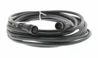


E69-DF5
Extender Cable, Rugged Rotary Encoder, 55m
- Manufacturer: OMRON INDUSTRIAL AUTOMATION
- Product type:
- SVHC: To Be Advised
| Delivery and price | |
|---|---|
| Units per pack | 1 |
| Price | 209.93 € |
| Current stock | 10+ |
| Lead time | 30 days |
**Slim Encoder with Diameter of 50 mm E6C3-A**

CSM_E6C3-A_DS_E_8_2

## **Rugged Rotary Encoder**

- Absolute model.

- External diameter of 50 mm.

- Resolution of up to 1,024 (10-bit).

- IP65 (improved oil-proof protection with sealed bearings)

- Optimum angle control possible in combination with PLC or Cam Positioner.

Be sure to read _Safety Precautions_ on page 7. ~~a~~

For the most recent information on models that have been certified for safety standards, refer to your OMRON website.

## **Ordering Information**

**Encoders [Refer to** _**Dimensions**_ **on page 8.]**

|**Power supply**<br>**voltage**|**Output configu-**<br>**ration**<br>~~——eocC"C—"_""|“_o®»v~~|**Output**<br>**code**<br>~~——eocC"C—"_""|“_o®»v~~<br>~~——_~~|**Resolution (pulses/rotation)**<br>~~——eocC"C—"_""|“_o®»v~~<br>~~——_~~|**Connection method**<br>)<br>~~——eocC"C—"_""|“_o®»v~~|**Model**|
|---|---|---|---|---|---|
|12 to 24 VDC|Open-collector<br>output (NPN)<br>~~——eocC"C—"_""|“_o®»v~~|Gray<br>~~——eocC"C—"_""|“_o®»v~~<br>~~——_~~|256, 360, (720)*2<br>~~——eocC"C—"_""|“_o®»v~~<br>~~——_~~|Pre-wired Connector<br>Model (1 m)<br>~~——eocC"C—"_""|“_o®»v~~|**E6C3-AG5C-C (resolution) 1M**<br>Example: E6C3-AG5C-C  256P/R 1M|
||||256, 360, 720, 1,024<br>~~——eocC"C—"_""|“_o®»v~~<br>~~——_~~<br>~~ee~~|Pre-wired Model (1 m)<br>*1<br>~~——eocC"C—"_""|“_o®»v~~|**E6C3-AG5C (resolution) 1M**<br>Example: E6C3-AG5C  256P/R 1M|
|||Binary<br>~~——_~~<br>~~>~~|32, 40<br>~~——_~~<br>~~>~~||**E6C3-AN5C (resolution) 1M**<br>Example: E6C3-AN5C  32P/R 1M|
|||BCD<br>~~>~~<br>~~>~~|6, 8, 12<br>~~>~~<br>~~>~~||**E6C3-AB5C (resolution) 1M**<br>Example: E6C3-AB5C  6P/R 1M|
||Open-collector<br>output (PNP)|Gray<br>~~>~~|256, 360, 720, 1,024<br>~~>~~||**E6C3-AG5B (resolution) 1M**<br>Example: E6C3-AG5B  256P/R 1M|
|||Binary<br>~~>.~~|32, 40<br>~~>.~~||**E6C3-AN5B (resolution) 1M**<br>Example: E6C3-AN5B  32P/R 1M|
|||BCD<br>~~>.~~<br>~~a~~|6, 8, 12<br>~~>.~~<br>~~a~~||**E6C3-AB5B (resolution) 1M**<br>Example: E6C3-AB5B  6P/R 1M|
|5 VDC|Voltage output<br>~~a~~|Binary|256||**E6C3-AN1E 256P/R 1M**|
|12 VDC|||||**E6C3-AN2E 256P/R 1M**|


- *1. Standard models are also available with 2-m cables. When ordering, specify the cable length at the end of the model number (example: E6C3-AG5C 360P/R 2M).

- *2. When connecting to the H8PS, use the E6C3-AG5C-C 256, 360, 720P/R. (Only a 2-m cable is available for the 720P/R Model.) For the 360/720 resolutions, 2-m cables are standard in-stock.

## **Accessories (Order Separately)**

**[Dimensions: Refer to** _**Accessories**_ **on page 8 for Extension Cable dimensions and** _**Accessories**_ **for the dimensions of other accessories.]**

|**Name**|**Model**<br>~~———,~~|**Remarks**|**Remarks**|
|---|---|---|---|
|Couplings<br>~~-—~~|**E69-C08B**<br>~~E—~~|---||
||**E69-C68B**<br>~~———~~<br>~~-—~~|Different end diameter (6 to 8 mm)<br>||
|Flanges<br>~~-—~~<br>~~-—~~|**E69-FCA03**<br>~~-—~~|---<br>||
||**E69-FCA04**<br>~~-—~~<br>~~a~~<br>~~-—~~|E69-2 Servo MountingBracket provided.<br><br>~~a~~||
|Servo Mounting Bracket<br>~~-—~~<br>~~-—~~|**E69-2**<br>~~-—~~<br>~~a~~<br>~~-—~~|Provided with E69-FCA04 Flange.<br><br>~~a~~||
|Extension Cable<br><br>~~-—~~|**E69-DF5**<br><br>~~a~~<br>~~-—~~<br>~~E—~~|5 m<br>~~I~~<br>~~a~~|Applicable to the E6C3-AG5C-C.<br>Models are also available with 15-m and 98-m cables.<br>~~——~~~|
||**E69-DF10**<br>~~a~~<br>~~-—~~<br>~~/-——~~|10 m<br>~~a~~<br>~~——~~~||
||**E69-DF20**<br>~~——~~|20 m<br>~~——~~~||


Refer to _Accessories_ for details.

**1** ~~a~~

**E6C3-A**

## **Ratings and Specifications**

|**Item**<br>**Model**|**Item**<br>**Model**|**E6C3-**<br>**AG5C-C**|**E6C3-**<br>**AG5C**|**E6C3-**<br>**AN5C**|**E6C3-**<br>**AB5C**|**E6C3-**<br>**AG5B**|**E6C3-**<br>**AN5B**|**E6C3-**<br>**AB5B**|**E6C3-**<br>**AN1E**|**E6C3-**<br>**AN2E**|
|---|---|---|---|---|---|---|---|---|---|---|
|**Power supply voltage**||12 VDC−10% to 24 VDC +15%, ripple (p-p): 5% max.|||||||5 VDC<br>±5%|12 VDC<br>±10%|
|**Current consumption*1**||70 mA max.|||||||||
|**Resolution*2 **<br>**(pulses/rotation)**||256, 360,<br>720|256, 360,<br>720, 1,024|32, 40|6, 8, 12|256, 360,<br>720, 1,024|32, 40|6, 8, 12|256||
|**Output code**||Gray code||Binary|BCD|Gray code|Binary|BCD|Binary||
|**Output configuration**||NPN open-collector output||||PNP open-collector output|||Voltage output||
|**Output capacity**||Applied voltage: 30 VDC max.<br>Sink current: 35 mA max.<br>Residual voltage: 0.4 V max. (at sink current of 35 mA)||||Source current: 35 mA max.<br>Residual voltage: 0.4 V max.<br>(at source current of 35 mA)|||Output re-<br>sistance:<br>2.4 kΩ|Output re-<br>sistance:<br>8.2 kΩ|
||||||||||Sink current: 35 mA max.<br>Residual voltage: 0.4 V<br>max. (at sink current of<br>35 mA)||
|**Rise and fall times of output**||1μs max. (Cable length: 2 m, Sink current: 35 mA)|||||||Rise: 3μs<br>max.,<br>Fall: 1μs<br>max.|Rise: 10μs<br>max.,<br>Fall: 1μs<br>max.|
|**Maximum response**<br>**frequency*3**||20 kHz|||||||10 kHz||
|**Logic**||Negative logic (high = 0, low = 1)||||Positive logic (high = 1, low = 0)|||||
|**Direction of rotation*4**||Output code increases for CW (as viewed from end of shaft).|||||||Switched using rotation di-<br>rection input.||
|**Strobe signal**||None||Supported||None|Supported||None||
|**Positioning signal**||None|||Supported|None||Supported|None||
|**Parity signal**||None||Supported<br>(even)|None||Supported<br>(even)|None|||
|**Starting torque**||10 mN·m max. at room temperature, 30 mN·m max. at low temperature|||||||||
|**Moment of inertia**||2.3×10⁻⁶kg·m2|||||||||
|**Shaft loading**|**Radial**|80 N|||||||||
||**Thrust**|50 N|||||||||
|**Maximum permissible speed**||5,000 r/min|||||||||
|**Ambient temperature range**||Operating:−10 to 70°C (with no icing), Storage:−25 to 85°C (with no icing)|||||||||
|**Ambient humidity range**||Operating/Storage: 35% to 85% (with no condensation)|||||||||
|**Insulation resistance**||20 MΩmin. (at 500 VDC) between current-carrying parts and case|||||||||
|**Dielectric strength**||500 VAC, 50/60 Hz for 1 min between current-carrying parts and case|||||||||
|**Vibration resistance**||Destruction: 10 to 500 Hz, 150 m/s2or 2-mm double amplitude for 11 min 3 times each in X, Y, and Z|||||||directions||
|**Shock resistance**||Destruction: 1,000 m/s23 times each in X, Y, and Z directions|||||||||
|**Degree of protection**||IEC 60529 IP65, in-house standards: oilproof|||||||||
|**Connection method**||Connector<br>Models*6|Pre-wired Models (Standard cable length: 1 m)||||||||
|**Material**||Case: Aluminum, Main unit: Aluminum, Shaft: SUS303|||||||||
|**Weight (packed state)**||Approx. 300 g|||||||||
|**Accessories**||Instruction manual  Note: Coupling, mounting bracket and hex-head spanner are sold separately.|||||||||


- *1. An inrush current of approximately 6 A will flow for approximately 0.8 ms when the power is turned ON.

- *2. The code is as follows:

|**Output**<br>**code**|**Resolu-**<br>**tion**|**Code No.**|
|---|---|---|
|Binary|32|1 to 32|
||40|1 to 40|
||256<br>|0 to 255<br>|
|BCD|6|0 to 5|
||8|0 to 7|
||12|0 to 11|
|Gray|256|0 to 255|
||360|76 to 435 (gray after 76)|
||720|152 to 871 (gray after 152)|
||1,024|0 to 1,023|


- *3. The maximum electrical response speed is determined by the resolution and maximum response frequency as follows:

Maximum electrical response speed (rpm) = Maximum response frequency × 60 Resolution

This means that the Rotary Encoder will not operate electrically if its speed exceeds the maximum electrical response speed.

- *4. For the E6C3-AN1E and E6C3-AN2E, the rotation direction input (wire color: pink) can be connected to high (Vcc) to increase the output code for CW rotation and connected to low (0 V) to 120˚ decrease the output code for CW rotation. E6C3-AN1E: High = 1.5 to 5 V, Low = 0 to 0.8

**==> picture [128 x 88] intentionally omitted <==**

**----- Start of picture text -----**<br>
120˚<br>Cut face D<br>120˚ 40 dia.<br>**----- End of picture text -----**<br>


V

E6C3-AN2E: High = 2.2 to 12 V, Low = 0 to 1.2 V

Read the code 10 μs or more after the LSB (2[0] ) of the code changes for the E6C3-AN1E or E6C3-AN2E.

- *5. The minimum address of the absolute code is output when cut face D on the shaft and the cable connection direction are as shown in the diagram at the right (output position range: ±15°).

- *6. Resolution of 360 or 720: Standard cable length: 2 m Resolution of 256: Standard cable length: 1 m

**2**

**E6C3-A**

## **I/O Circuit Diagrams**

**==> picture [511 x 382] intentionally omitted <==**

**----- Start of picture text -----**<br>
Model E6C3-AG5C/-AG5C-C E6C3-AG5B E6C3-AN5C E6C3-AN5B<br>12 to 24 V 12 to 24 V 12 to 24 V 12 to 24 V<br>Output Output Output Output<br>E6C3-A 35 mA max. E6C3-A 35 mA  E6C3-A 35 mA max. E6C3-A 35 mA<br>Output  main circuit 30 VDC main circuit max. main circuit 30 VDC main circuit max.<br>Circuits 0 V 0 V 0 V 0 V<br>Shield  Shield  Shield  Shield<br>GND GND GND GND<br>Note: The circuit is the same for  Note: The circuit is the same for  Note: The circuit is the same for  Note: The circuit is the same for<br>all bit outputs. all bit outputs. all bit outputs. all bit outputs.<br>Each E6C3-A Rotary Encoder  Each E6C3-A Rotary Encoder  Each E6C3-A Rotary Encoder  Each E6C3-A Rotary Encoder<br>has one main circuit. has one main circuit. has one main circuit. has one main circuit.<br>Direction of rotation: CW (as viewed from the end of the shaft) Direction of rotation: CW (as viewed from the end of the shaft)<br>Resolution/40<br>No. 1 5 10 15 20 25 30 35 40<br>2 [0] OFFON Strobe signal OFFON<br>22 [1][2] OFFOFFONON 222 [0][1][2] OFFOFFOFFONONON<br>2 [3] OFFON 2 [3] OFFON<br>Output mode 22 [4][5] OFFOFFONON Parity  signal 22 [4][5] OFFOFFOFFONONON<br>2 [6] OFFON<br>2 [7] OFFON Resolution of 32 Absolute angle 360˚C 9˚ 18˚ 27˚<br>2.25˚ 2.25˚<br>ON A = 11.25˚<br>2 [8] OFF B = 6˚ Strobe B<br>Address2 [9] OFFON 0 1 2 3 4 5 6 7 8 9 1011121314151617181920212223242526272829303132333435363738394041424344454647484950515253545556575859606162636465 C = 3˚  signal 4.5˚A9˚ 0.5˚ min.  0.5˚ min.<br>Other bit<br> signals<br>**----- End of picture text -----**<br>


## **Connection Specifications**

## **Connector Models**

|**Model**|**E6C3-AG5C-C**|
|---|---|
||**Output signal**|
|**Pin No.**|**8-bit (256)**<br>**9-bit (360)**|
|**1**|}<br>Connected<br>internally<br>Not connected<br>28|
|**2**||
|**3**|25<br>25|
|**4**|21<br>21|
|**5**|20<br>20|
|**6**|27<br>27|
|**7**|24<br>24|
|**8**|22<br>22|
|**9**|23<br>23|
|**10**|26<br>26|
|**11**|Shield (ground)|
|**12**|12 to 24 VDC|
|**13**|0 V (common)|


* Connector: RP13A-12PD-13SC (Hirose Electric Co., Ltd.) Note: Normally connect GND to 0 V or to an external ground.

## **Pre-wired Models**

|**E6C3-AG5C/E6C3-AG5B**|**E6C3-AG5C/E6C3-AG5B**|
|---|---|
|**Output signal**||
|**8-bit (256)**<br>**9-bit**|**(360)**<br>**10-bit (720 or**<br>**1,024)**|
|20<br>2|0<br>20|
|21<br>2|1<br>21|
|22<br>2|2<br>22|
|23<br>2|3<br>23|
|24<br>2|4<br>24|
|25<br>2|5<br>25|
|26<br>2|6<br>26|
|27<br>2|7<br>27|
|Not connected<br>2|8<br>28|
|Not connected<br>Not con|nected<br>29|
|Shield (ground)||
|12 to 24 VDC||
|0 V (common)||


**3**

**E6C3-A**

## **I/O Circuit Diagrams**

**==> picture [512 x 432] intentionally omitted <==**

**----- Start of picture text -----**<br>
Model E6C3-AB5C E6C3-AB5B E6C3-AN1E E6C3-AN2E<br>2.4 kΩ 5 VDC 8.2  kΩ 12 VDC<br>E6C3-Amain circuit 35 mA max. Output0 V E6C3-Amain circuit 35 mA max. Output0 V<br>12 to 24 V 12 to 24 V Shield  GND Shield  GND<br>E6C3-A 35 mA max.Output E6C3-A 35 mA  Output Note: The circuit is the same for all  Note: The circuit is the same for all<br>Output  main circuit 30 VDC0 V main circuit max. 0 V bit outputs. bit outputs.<br>circuits<br>Shield  GND Shield  GND Rotation Direction Input Circuit<br>Note: The circuit is the same for all  Note: The circuit is the same for all  Vcc (5 V or 12 V)<br>bit outputs. bit outputs.<br>E6C3-Amain circuit Input<br>Note: If the input is connected to Vcc, the<br>output will increase for CW rotation<br>0 V and if the input is connected to 0 V,<br>the output code will decrease for<br>CW rotation.<br>Direction of rotation: CW (as viewed from end of shaft) Direction of rotation: CW (as viewed from end of shaft) if rotation<br>Resolution/12 direction input is high and CCW (as viewed from end of shaft) if<br>No. 0 1 2 3 4 5 6 7 8 9 10 11 rotation direction input is low.<br>Positioning  ON<br>signal OFF<br>Strobe signals OFFON Shaft angle:  °<br>2 [0] OFFON 360˚ T±T/2 T±T/2<br>2 [1] OFFON 2 [0] (H) 1 2 3 4 5 6 7 8 9 10 11 12 13 14 15 16 17 18 19<br>ON 2 [1] (L)<br>2 [2] OFF<br>ON 2 [2]<br>Output  2 [3] OFFON 2 [3]<br>mode 2 [0 ] × 10 OFF<br>2 [4]<br>2 [5]<br>Resolution of 8A = 45˚, B = 22.5˚ Absolute angle 0˚ 30˚7.5˚C 60˚ 7.5˚90˚ 22 [6][7]<br>C = 11.25˚ Strobe T=360˚/256≈1.4˚<br>Resolution of 6  signal 15˚B<br>A = 60˚, B = 30˚ 30˚A 0.5˚ 0.5˚<br>C = 15˚ Positioning<br>signal 1˚<br>**----- End of picture text -----**<br>


## **Connection Specifications**

## **Pre-wired Models**

|**Model**|**E6C3-AN5C/-AN5B**|**E6C3-AB5C/-AB5B**|**E6C3-AB5C/-AB5B**|**E6C3-AN1E/-AN2E**|
|---|---|---|---|---|
||**Output signal**|**Output signal**||**Output signal**|
|**Wire color**|**6-bit (32 or 40)**|**3-bit (6 or 8)**|**5-bit (12)**|**8-bit (256)**|
|**Brown**|20|20|20|20|
|**Orange**|21|21|21|21|
|**Yellow**|22|22|22|22|
|**Green**|23|Not connected|23|23|
|**Blue**|24|Not connected|20 ×10|24|
|**Purple**|25|Not connected|Not connected|25|
|**Gray**|Parity|Positioning|Positioning|26|
|**White**|Strobe|Strobe|Strobe|27|
|**Pink**|Not connected|Not connected|Not connected|Rotation Direction Input|
|**Light blue**|Not connected|Not connected|Not connected|Not connected|
|**---**|Shield (ground)||||
|**Red**|12 to 24 VDC|||5 or 12 VDC|
|**Black**|0 V (common)||||


Note: Normally connect GND to 0 V or to an external ground.

**4**

**E6C3-A**

**Connection Example**

## **H8PS Cam Positioner Connection Example**

## **Ordering Information**

## **Specifications**

||**Ordering Information**|**Specifications**||
|---|---|---|---|
|H8PS<br>E6C3-AG5C-C|**Model**<br>**H8PS-8A**<br>**H8PS-8AP**<br>**H8PS-8AF**<br>**H8PS-8AFP**<br>**H8PS-16A**<br>**H8PS-16AP**<br>**H8PS-16AF**<br>**H8PS-16AFP**<br>**H8PS-32A**<br>**H8PS-32AP**<br>**H8PS-32AF**<br>**H8PS-32AFP**|**Rated voltage**|24 VDC|
|||**Cam precision**|0.5°(for 720 resolution), 1°(for 256/360 resolution)|
|||**No. of output points**|8-point output type:<br>8 cam outputs, 1 RUN output, 1 pulse output<br>16-point output type:<br>16 cam outputs, 1 RUN output, 1 pulse output<br>32-point output type:<br>32 cam outputs, 1 RUN output, 1 pulse output|
|||**Encoder response**|RUN mode, test mode:<br>256/360 resolution .....  1,600 r/min max. (1,200 r/min when<br>advance compensation is set for four cams or more)<br>720 resolution ............  800 r/min max. (600 r/min when ad-<br>vance compensation is set for four cams or more)|
|||**Additional functions**|•Origin compensation (zeroing)<br>•Rotation direction switching<br>•Angle display switching<br>•Teaching<br>•Pulse output<br>•Angle/number of rotations display switching<br>•Puncture*<br>•Angle advance<br>•Number of rotations alarm output<br>•Setting with support software (order separately) *|


* For 16-point and 32-point output types only

**5**

**E6C3-A**

## **Programmable Controller Connection Example**

## **Connection to the CP1E**

**==> picture [506 x 453] intentionally omitted <==**

**----- Start of picture text -----**<br>
 (720 Resolution)  Wiring between the E6C3-AG5C and CP1E Output Timing<br>E6C3-AG5C out- CP1E input<br>E6C3-AG5C put signal signal 0 90 180E6C3-AG5C angle360 540 659<br>Brown (2 [0] ) 00000<br>Orange (2 [1] ) 00001 01000<br>Yellow (2 [2] ) 00002 01001<br>Green (2 [3] ) 00003 01002<br>CP1E-N20D@-@ Blue (2 [4] ) 00004<br>Purple (2 [5] ) 00005<br>Gray (2 [6] ) 00006<br>White (2 [7] ) 00007<br>Pink (2 [8] ) 00008<br>Light blue (2 [9] ) 00009<br>Ladder Programming Example DM Area Setting Example for Comparison Table<br>000090000800008 2000920009 2000920008 Always ON Flag25313 BCD(24)200201 Converted to binary (CIO 200) and BCD (CIO 201).  DM6200620162026203 0000054000900360 Lower limit 1Upper limit 1Lower limit 2Upper limit 2 Bit CIO 20300Bit CIO 20301<br>6204 0180 Lower limit 3<br>00007 20008 20007 CLC (41) (0) is set to carry flag. 6205 0659 Upper limit 3 Bit CIO 20302<br>00007 20008 6206 0000 Lower limit 4<br>Not used in<br>Resolution is 720, so 152 is<br>00006 20007 SUB(31) subtracted.  this example.<br>20006 201 No subtraction would be  6231 0000 Upper limit 16<br>00006 20007 #0152 necessary for resolution of 256<br>202 or 1,024.<br>00005 20006 If resolution was 360, 76 would<br>20005 be subtracted.<br>00005 20006 BCMP(68) TABLE COMPARE Instruction<br>202 If the Encoder value (CIO 202)<br>00004 20005 20004 Converts gray code to binary  DM6200203 is within a range in the conversion table set in DM<br>00004 20005 (CIO 200). Sets the unused  6200 to DM 6231, the corresponding bit in CIO 203<br>bits (10 to 15 bits)  20300 will turn ON.<br>00003 20004 20003 of CIO 200 to  01000<br>unused (always 0). 20301<br>00003 20004 01001 Output<br>20302<br>00002 20003 01002<br>20002<br>00002 20003<br>00001 20002<br>20001<br>00001 20002<br>00000 20001<br>20000<br>00000 20001<br>**----- End of picture text -----**<br>


For details, refer to the following manual: CP1E-E@@SD@-@/CP1E-N@@S@D@-@/CP1E-E@@D@-@/CP1E-N@@D@-@/ **CP1E** CP1E-NA@@D@-@ SYSMAC CP Series CP1E CPU Unit Instructions Reference Manual (Cat. No. W483).

**6**

**E6C3-A**

## **Safety Precautions**

## **Refer to** _**Warranty and Limitations of Liability**_ **.**

## **WARNING**

**This product is not designed or rated for ensuring safety of persons either directly or indirectly. Do not use it for such purposes.**

## **Precautions for Correct Use**

Do not use the Encoder under ambient conditions that exceed the ratings.

## ● **Wiring**

## **Connections**

Cable Extension Characteristics

- Conditions will change according to frequency, noise, and other factors. As a guideline, use a cable length of 10 m* or less.

* Recommended Cable

Conductor cross section: 0.2 mm[2]

Spiral shield

Conductor resistance: 92 Ω/km max. (20°C) Insulation resistance: 5 Ω/km min. (20°C)

- The output waveform startup time changes not only according to the length of the cable, but also according to the load resistance and the cable type.

- Extending the cable length not only changes the startup time, but also increases the output residual voltage.

## ● **Connection**

Spurious pulses may be generated when power is turned ON and OFF. Wait at least 0.1 s after turning ON the power to the Encoder before using the connected device, and stop using the connected device at least 0.1 s before turning OFF the power to the Encoder. Also, turn ON the power to the load only after turning ON the power to the Encoder.

**7**

**E6C3-A**

(Unit: mm)

## **Dimensions**

Tolerance class IT16 applies to dimensions in this datasheet unless otherwise specified.

## **Encoder**

**==> picture [502 x 370] intentionally omitted <==**

**----- Start of picture text -----**<br>
E6C3-A @ 5 @ (58)<br>20 38<br>E6C3-AN @ E Cut face D: Smallest adress position (±15˚)<br>40±0.1 dia. 120˚±0.1 10 (15) 1 5<br>8 [ +0        ] −0.018 [ dia.]<br>ce 12 dia. 1 a<br>30 -0.021  [0] [dia.]<br>50 dia.<br>D5y We’ Three, M4 Depth: 5 holes;  120˚±0.1 ae + 6 tL<br>mm 8.8<br>s e 10 a 6<br>Note: The E69-C08B Coupling is sold  ; e<br>separately.  6-dia. oil-resistant PVC-insulated shielded cable with 12<br>conductors (Conductor cross section: 0.2 mm [2] , Insulator<br>diameter: 1.1 mm), Standard length: 1 m<br>E6C3-AG5C-C (58)<br>20 38<br>Cut face D: Smallest adress position (±15˚)<br>40±0.1 dia. 120˚±0.1 10 (15) 1 5<br>8  [+0] -0.018  [dia.]<br>12 dia. 1<br>30 -0.021  [+0] [dia.]<br>50 dia.<br>wy Three, M4 Depth: 5 holes;  R 120˚±0.1 E 6 RY<br>mm 8.8 Connector: RP13A-12PD-13SC<br>10 6 (Hirose Electric Co., Ltd.)<br>— 37<br>Note: The E69-C08B Coupling is sold<br>Gear<br>separately.<br>6-dia. oil-resistant PVC-insulated shielded cable with 12<br>conductors (Conductor cross section: 0.2 mm [2] , Insulator<br>diameter: 1.1 mm), Standard length: 1 m, Standard length for<br>resolution of 360 or 720: 2 m<br>**----- End of picture text -----**<br>


## **Accessories (Order Separately)**

## **Extension Cable**

**E69-DF5**

**==> picture [273 x 79] intentionally omitted <==**

**----- Start of picture text -----**<br>
39.6 5,000 37<br>16.9 di e a. a = 1 6.9 dia.<br>aS *2 *1 *3 Py<br>*1. 6-dia. oil-resistant PVC-insulated shielded cable with 12 conductors (Conductor cross section:<br>0.2 mm [2] , Insulator diameter: 1.1 mm), Standard length: 5 m<br>*2. Connects to connector on E6C3-AG5C-C.<br>**----- End of picture text -----**<br>


   - *3. Connects to H8PS Cam Positioner.

- Note: 1. The E69-DF5 (5 m) is also available with the following cable lengths: 10 m, 15 m, 20 m, and 98 m. 2. Cable can be extended to 100 m when the H8PS Cam Positioner is connected.

**Couplings Flanges Servo Mounting Bracket E69-C08B E69-FCA03 E69-2 E69-C68B E69-FCA04** Refer to _Accessories_ for details.

**8** ~~a~~

## Terms and Conditions Agreement

## Read and understand this catalog.

Please read and understand this catalog before purchasing the products.  Please consult your OMRON representative if you have any questions or comments.

## Warranties.

(a) Exclusive Warranty. Omron’s exclusive warranty is that the Products will be free from defects in materials and workmanship for a period of twelve months from the date of sale by Omron (or such other period expressed in writing by Omron). Omron disclaims all other warranties, express or implied.

(b) Limitations. OMRON MAKES NO WARRANTY OR REPRESENTATION, EXPRESS OR IMPLIED, ABOUT NON-INFRINGEMENT, MERCHANTABILITY OR FITNESS FOR A PARTICULAR PURPOSE OF THE PRODUCTS. BUYER ACKNOWLEDGES THAT IT ALONE HAS DETERMINED THAT THE

PRODUCTS WILL SUITABLY MEET THE REQUIREMENTS OF THEIR INTENDED USE.

Omron further disclaims all warranties and responsibility of any type for claims or expenses based on infringement by the Products or otherwise of any intellectual property right. (c) Buyer Remedy. Omron’s sole obligation hereunder shall be, at Omron’s election, to (i) replace (in the form originally shipped with Buyer responsible for labor charges for removal or replacement thereof) the non-complying Product, (ii) repair the non-complying Product, or (iii) repay or credit Buyer an amount equal to the purchase price of the non-complying Product; provided that in no event shall Omron be responsible for warranty, repair, indemnity or any other claims or expenses regarding the Products unless Omron’s analysis confirms that the Products were properly handled, stored, installed and maintained and not subject to contamination, abuse, misuse or inappropriate modification. Return of any Products by Buyer must be approved in writing by Omron before shipment. Omron Companies shall not be liable for the suitability or unsuitability or the results from the use of Products in combination with any electrical or electronic components, circuits, system assemblies or any other materials or substances or environments. Any advice, recommendations or information given orally or in writing, are not to be construed as an amendment or addition to the above warranty.

See http://www.omron.com/global/ or contact your Omron representative for published information.

## Limitation on Liability; Etc.

OMRON COMPANIES SHALL NOT BE LIABLE FOR SPECIAL, INDIRECT, INCIDENTAL, OR CONSEQUENTIAL DAMAGES, LOSS OF PROFITS OR PRODUCTION OR COMMERCIAL LOSS IN ANY WAY CONNECTED WITH THE PRODUCTS, WHETHER SUCH CLAIM IS BASED IN CONTRACT, WARRANTY, NEGLIGENCE OR STRICT LIABILITY. Further, in no event shall liability of Omron Companies exceed the individual price of the Product on which liability is asserted.

## Suitability of Use.

Omron Companies shall not be responsible for conformity with any standards, codes or regulations which apply to the combination of the Product in the Buyer’s application or use of the Product. At Buyer’s request, Omron will provide applicable third party certification documents identifying ratings and limitations of use which apply to the Product. This information by itself is not sufficient for a complete determination of the suitability of the Product in combination with the end product, machine, system, or other application or use. Buyer shall be solely responsible for determining appropriateness of the particular Product with respect to Buyer’s application, product or system. Buyer shall take application responsibility in all cases.

NEVER USE THE PRODUCT FOR AN APPLICATION INVOLVING SERIOUS RISK TO LIFE OR PROPERTY OR IN LARGE QUANTITIES WITHOUT ENSURING THAT THE SYSTEM AS A WHOLE HAS BEEN DESIGNED TO ADDRESS THE RISKS, AND THAT THE OMRON PRODUCT(S) IS PROPERLY RATED AND INSTALLED FOR THE INTENDED USE WITHIN THE OVERALL EQUIPMENT OR SYSTEM.

## Programmable Products.

Omron Companies shall not be responsible for the user’s programming of a programmable Product, or any consequence thereof.

## Performance Data.

Data presented in Omron Company websites, catalogs and other materials is provided as a guide for the user in determining suitability and does not constitute a warranty. It may represent the result of Omron’s test conditions, and the user must correlate it to actual application requirements. Actual performance is subject to the Omron’s Warranty and Limitations of Liability.

## Change in Specifications.

Product specifications and accessories may be changed at any time based on improvements and other reasons. It is our practice to change part numbers when published ratings or features are changed, or when significant construction changes are made. However, some specifications of the Product may be changed without any notice. When in doubt, special part numbers may be assigned to fix or establish key specifications for your application. Please consult with your Omron’s representative at any time to confirm actual specifications of purchased Product.

## Errors and Omissions.

Information presented by Omron Companies has been checked and is believed to be accurate; however, no responsibility is assumed for clerical, typographical or proofreading errors or omissions.

**In the interest of product improvement, specifications are subject to change without notice.**

## **OMRON Corporation**

## **Industrial Automation Company**

2019.4

**http://www.ia.omron.com/**

(c)Copyright OMRON Corporation 2019 All Right Reserved.
Updated at June 9, 2026
With a legacy spanning over 80 years, Omron Industrial Automation is a globally recognized leader in the manufacture of advanced industrial control and automation components. Renowned for their reliability and engineering excellence, Omron delivers comprehensive solutions that enhance efficiency, machine safety, and precision across a wide range of manufacturing environments. Our extensive portfolio of Omron products is heavily focused on their industry-leading sensing and switching technologies. We offer a vast selection of sensors, excelling specifically in high-performance proximity sensors, light sensors, and temperature sensors. Complementing this range are robust switching solutions, featuring a deep inventory of power relays, solid-state relays, safety relays, and essential relay accessories designed for demanding operational requirements. Beyond sensing and switching, Omron is highly regarded for its precision automation and process control equipment. Our selection features highly accurate temperature controllers, versatile process controllers, and sophisticated panel displays and instrumentation. To support these fundamental systems, we also supply dependable Omron power supplies, notably AC/DC converters, alongside vital connectivity components like DIN rail terminal blocks to ensure secure, efficient, and complete industrial setups.
About Novapart
Novapart is a B2B electronic component broker specialising in stock shortages and cost reduction. We source hard-to-find parts and identify compliant alternatives across a catalogue of 410,000+ components from 500+ manufacturers.
Learn more →Stock Shortage Specialist
When a component is unavailable, discontinued or has an unacceptable lead time, we tap into our network of vetted European and Asian distributors to source what you need — without compromising on quality or traceability.
Request a quote →Compliant Alternatives
We identify pin-to-pin, electrically equivalent substitutes that meet the same certifications (RoHS, AEC-Q100, REACH) as your original specification — validated against datasheets, not just part numbers. Often at a lower cost.
BOM Analysis service →