
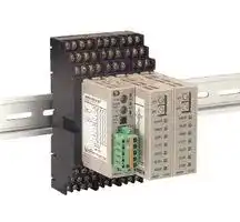


E5ZE-CBL200
I/O Cable, Temperature Controller, 2 m
- Manufacturer: OMRON INDUSTRIAL AUTOMATION
- Product type: Controller Accessories
- SVHC: No SVHC (16-Jan-2020)
| Delivery and price | |
|---|---|
| Units per pack | 1 |
| Price | 139.35 € |
| Current stock | 10+ |
| Lead time | 30 days |
Multi--point Temperature Controller

## **E5ZE-8 j D1 j B-V2**

## Controls Up to Eight Zones, Built-in DeviceNet Communications

- H Applications include plastic injection and extrusion machines, and continuous temperature control processes

- H DeviceNet allows the controller to communicate with a remote I/O master without programming, or communicate directly with an Omron PLC via explicit messaging

- H Fast sampling rate of 0.2 s for 8 inputs

- H Optional 1/4 DIN size Display Unit shows temperature and settings for each zone without using software

- H 3-year warranty

## Ordering Information

## J **TEMPERATURE CONTROLLERS**

|Control<br>**i**<br>po nts|Control method|Control<br>output|Heater o**p**en circuit**/**<br>**SSR** **f**<br>**l** **d**<br>**i**<br>au t<br>etect on|**Part number**|**Part number**|
|---|---|---|---|---|---|
|||||Thermocouple|Platinum resistance thermometer|
|8|Heat<br>**(S**<br>**N**<br>**1)**<br>ee<br>ote|Volta**g**e|Yes(See Note 2)|**E5ZE-8AQHD1TCB-V2**|**E5ZE-8AQHD1PB-V2**|
||||No|**E5ZE-8AQAD1TCB-V2**|**E5ZE-8AQAD1PB-V2**|
|||Current||**E5ZE-8ACAD1TCB-V2**|**E5ZE-8ACAD1PB-V2**|
||Heat and cool|Volta**g**e|Yes(See Note 2)|**E5ZE-8VQHD1TCB-V2**|**E5ZE-8VQHD1PB-V2**|
||||No|**E5ZE-8VQAD1TCB-V2**|**E5ZE-8VQAD1PB-V2**|
|||Current||**E5ZE-8VCAD1TCB-V2**|**E5ZE-8VCAD1PB-V2**|


- Note: 1. The output operation can be switched to provide cooling control.

   2. Models are available without the Heater open circuit/SSR fault detection functions.

   3. Number of connectable units will be limited according to remote I/O points at host system.

## J **ACCESSORIES (ORDER SEPARATELY)**

|J **ACCESSORIES (ORDER SEPARATELY)**|**ACCESSORIES (ORDER SEPARATELY)**||
|---|---|---|
|Description|Specifications|**Part number**|
|Dis**p**la**y**unit shows<br>**i**<br>**ll**<br>sett ngs, a ows<br>**programming** **without**<br>**software;** **1/4** **DIN** **size**|RS-232C connection; 100 to 240 VAC, 50/60 Hz supplyvoltage|**E5ZD-SDL1 AC100-240**|
||RS-232C connection; 24 VDC supplyvoltage|**E5ZD-SDL1 DC24**|
||1.5 m length cable from E5ZE to DisplayUnit, RS-232C with 25-pin connector|**ES100-CT022-202**|
||1.5 m length cable from E5ZE to DisplayUnit, RS-232C with 9-pin connector|**ES100-CT023-202**|
|Current transformer;<br>**order** **only** **if** **using** **heater**<br>burnout alarm function|50 A load, 5.8 mm hole dia.|**E54-CT1**|
||120 A load, 12 mm hole dia.|**E54-CT3**|
|Software|For setup and monitoring|**SYS-CONFIG V2.0**|
|I/O cable to E5ZE|2 m length cable connects XW2B-20G4 or XW2B-20G5 screw terminals for<br>control and current transformer inputs and alarm outputs; order 3 cables|**E5ZE-CBL200**|
|DeviceNet connectors|Color-coded terminals assure correct wiring;plugs into DeviceNetport; order 2|**XW4B-05C1-H1-D**|
||One-branch, T-branch tapwith three connectors|**DCN1-1C**|
||Three-branch, T-branch tapwith five connectors|**DCN1-3C**|
||Terminal block with terminating resistor: 121Ω|**DRS1-T**|


1

**E5ZE-8 V D1 V B-V2**

**E5ZE-8 V D1 V B-V2**

## Specifications

## J **TEMPERATURE CONTROLLER**

## **Ratings**

|J **TEMPERATURE CONTROLLER**<br>**Ratings**|J **TEMPERATURE CONTROLLER**<br>**Ratings**|**TEMPERATURE CONTROLLER**|
|---|---|---|
|Rated voltage||24 VDC|
|Permissible voltage fluctuation||85 to 110% of rated voltage|
|Power consumption||15 W +20% max. at 24 VDC|
|Sensor<br>in**puts**|Inputs|Thermocouple: K, J, T, E, L, U, N, R, S, B, W, and PL II<br>Platinum resistance thermometer: JPt 100, Pt 100|
||Input impedance|Thermocouple: 1 MΩmin.|
||Rated current|Platinum resistance thermometer: 1 mA|
|Control<br>outputs|Voltage output<br>(with short-circuit protection)|ON voltage: 12±1.2 VDC<br>OFF voltage: 0.5 VDC max.<br>Max. load current: 30 mA/output|
||Current output|Rated output range: 4 to 20 mA (4 +0/--0.6 mA for 0% output, 20 +2/--0 mA for 100% output)<br>Max. load resistance: 600Ω/output|
||Open-collector NPN output<br>(cooling only)|Max. voltage: 30 VDC<br>Max. load current: 50 mA/output<br>Residual voltage when ON: 2 VDC max.<br>Leakage current when OFF: 1 mA max.|
|Alarm outputs||Temperature alarms: Two outputs: alarm 1 and alarm 2 for all outputs in each word.<br>HB alarm (heater burnout detection): One output for all outputs in each word.<br>HS alarm (SSR fault detection): One output for all outputs in each word.<br>Temperature controller error output (memory, set value, or hardware error): One output<br>All outputs are NPN open-collector outputs with a max. voltage of 30 VDC and max. load<br>current of 50 mA/output.|
|Number of inputs||8 input points and 8 control points|
|Setting method||Set by communications|
|Control method||ON/OFF, hybrid of advanced PID and fuzzy logic control, or manual operation|
|Memory bank input||8 points for each control point<br>Designated through communication or memorybank designation input|
|Memory bank designation inputs||With contact signal input:<br>ON short--circuit resistance:<br>1 kΩmax.<br>OFF open resistance:<br>100 kΩmin.<br>With non-contact signal input: ON residual voltage:<br>2 VDC max.<br>OFF leakage current:<br>1 mA DC max.|
|Ambient temperature||Operating: 0°C to 55°C (32°F to 131°F) with no icing or condensation<br>Storage: --25°C to 65°C(--14°F to 149°F)with no icingor condensation|
|Ambient humidity||Operating: 35% to 85% RH|


**Temperature Ranges**

|**Temperature Ranges**|**Temperature Ranges**|||||
|---|---|---|---|---|---|
|Input<br>~~a~~||Temperature range<br>~~a~~<br>~~G~~||Setting (See Note 1)<br>~~a~~<br>~~G~~|Minimum units<br>~~a~~<br>~~G~~|
|Thermocou**p**le<br>~~Ce~~|K(CA)<br>~~a~~|--200_C to 1,300_C<br>~~a~~|--300_F to 2,300_F<br>~~a~~|0<br>~~a~~|1_**C** **o**r**0**.1_**C**<br>~~a~~<br>~~a~~<br>~~a~~<br>~~a~~<br>~~a~~<br>~~a~~<br>~~a~~<br>~~a~~<br>~~a~~<br>~~a~~<br>~~a~~|
||J(IC)<br>~~a~~|--100_C to 850_C<br>~~a~~|--100_F to 1,500_F<br>~~a~~|1<br>~~a~~||
||R<br>~~a~~|0_C to 1,700_C<br>~~a~~|0_F to 3,000_F<br>~~a~~|2<br>~~a~~||
||S<br>~~a~~|0_C to 1,700_C<br>~~a~~|0_F to 3,000_F<br>~~a~~|3<br>~~a~~||
||T(CC)<br>~~a~~|--200_C to 400_C<br>~~a~~|--300_F to 700_F<br>~~a~~|4<br>~~a~~||
||E(CRC)<br>~~a~~|0_C to 600_C<br>~~a~~|0_F to 1,100_F<br>~~a~~|5<br>~~a~~||
||B<br>~~a~~|100_C to 1,800_C<br>~~a~~|300_F to 3,000_F<br>~~a~~|6<br>~~a~~||
||N<br>~~a~~|0_C to 1,300_C<br>~~a~~|0_F to 2,300_F<br>~~a~~|7<br>~~a~~||
||L<br>~~a~~|--100_C to 850_C<br>~~a~~|--100_F to 1,500_F<br>~~a~~|8<br>~~a~~||
||U<br>~~a~~|--200_C to 400_C<br>~~a~~|--300_F to 700_F<br>~~a~~|9<br>~~a~~||
||W<br>~~a~~<br>~~es~~|0_C to 2,300_C<br>~~a~~|32_F to 4,100_F<br>~~a~~|A<br>~~a~~||
||PL II2<br>~~es~~<br>~~eneennnnnnnnnnnnnnEEnEEEEEEE~~|0_C to 1,300_C<br>~~eneennnnnnnnnnnnnnEEnEEEEEEE~~|0_F to 2,300_F<br>~~eneennnnnnnnnnnnnnEEnEEEEEEE~~|B<br>~~eneennnnnnnnnnnnnnEEnEEEEEEE~~||
|Platinum resistance<br>**h**<br>t ermometer<br>~~Ce~~|Pt100<br>~~es~~<br>~~eneennnnnnnnnnnnnnEEnEEEEEEE~~|--100.0_C to 500.0_C<br>~~eneennnnnnnnnnnnnnEEnEEEEEEE~~|--100.0_F to 900.0_F<br>~~eneennnnnnnnnnnnnnEEnEEEEEEE~~|0<br>~~eneennnnnnnnnnnnnnEEnEEEEEEE~~||
||JPt100<br>~~es~~<br>~~eneennnnnnnnnnnnnnEEnEEEEEEE~~<br>~~CO~~|--100.0_C to 500.0_C<br>~~eneennnnnnnnnnnnnnEEnEEEEEEE~~<br>~~CO~~|--100.0_F to 900.0_F<br>~~eneennnnnnnnnnnnnnEEnEEEEEEE~~<br>~~CO~~|1<br>~~eneennnnnnnnnnnnnnEEnEEEEEEE~~<br>~~CO~~||


- Note: 1. The factory setting is 0 (Type K for thermocouple input or Pt100 for platinum resistance thermometer input.)

   2. Platinel is a registered trademark of Englehard Industries.

2

**E5ZE-8 V D1 V B-V2**

**E5ZE-8 V D1 V B-V2**

## **Characteristics**

|**Characteristics**||
|---|---|
|Measurement precision|Thermocouple:<br>(±0.3% of the measured value or±2°C, whichever is larger)±1 digit max.<br>(±0.3% of the measured value or±3.6°F, whichever is larger)±1 digit max.<br>Platinum resistance thermometer:<br>(±0.3% of the measured value or±0.8°C, whichever is larger)±1 digit max.<br>(±0.3% of the measured value or±1.5°F, whichever is larger)±1 digit max.|
|Adjustable sensitivity|0.0°C to 99.9°C or 0.0°F to 99.9°F (0.1°increments), valid for ON/OFF control only.|
|Cooling coefficient|0.0 to 10.0 (0.1 increments)|
|Proportional band|0.0°C to 999.9°C or 0.0°F to 999.9°F (0.1°increments)<br>Cooling: coolingcoefficient× proportional band|
|Integral time|0 to 3,999 s (1-s increments)|
|Derivative time|0 to 3,999 s (1-s increments)|
|Control cycle|Heating or cooling: 1 to 99 s (1-s increments)|
|Sampling cycle|Approx. 200 ms/8 words|
|Dead band/overlap Band|--999°C to 999°C or --999°F to 999°F (1°increments)|
|Alarm set range|With 1°increments: --999°to 9,999°(0°to 9,999°with upper/lower limit alarms)<br>With 0.1°increments: --999.9°to 9,999.9° (0.0°to 9,999.9°with upper/lower limit alarms)|
|Fuzzy logic strength|0 to 99% (1% increments)|
|Fuzzy logic scale 1|0.2°to 999.9°(0.1°increments)|
|Fuzzy logic scale 2|0.02°to 99.99°(0.01°increments)|
|SV protection|Lithium battery backup|
|SV protection time|10 years min. at room temperature|
|Insulation resistance|20 MΩat 500 VDC between the FG terminal and analog input terminals|
|Dielectric strength|Leakage current of 1 mA max. between the FG terminal and analog input terminals when 500 VAC<br>is applied for 1 min.|
|Vibration resistance|Malfunction: 10 to 55 Hz with 15 m/s2 in X, Y, and Z directions for 8 min.<br>Destruction: 10 to 55 Hz with 20 m/s2 in X, Y, and Z directions for 8 min.|
|Shock resistance|Malfunction: 150 m/s2 max. 3 times each in±X,±Y, and±Z directions<br>Destruction: 200 m/s2 max. 3 times each in±X,±Y, and±Z directions|
|Degree of protection|IP00|
|Weight|Case-type Unit: 1,700gmax.|


- Note: 1. The measurement accuracy of the E5ZE used with a thermocouple B at 400°C or 750°F max. is not guaranteed. The following measurement accuracy values are applied to the E5ZE. K and T at --100°C max. and U: ±3°C ±1 digit max.

      - K and T at --100°F max. and U: ±5.4°F ±1 digit max. R, S, and W at 200°C max., and B at 1,000°C max.: ±4°C ±1 digit max. R, S, and W at 400°F max., and B at 1,800°F max.: ±7.2°F ±1 digit max.

   2. The measurement accuracy of the E5ZE used with any thermocouple is 1°C/°F. The thermocouple can be used under the following temperature ranges to increase the measurement accuracy to as high as 0.1°C/°F. K thermocouple: 0.0 °C to 1,300.0 °C, 0.0 °F to 2,300.0 °F T or U thermocouple: 0.0 °C to 400.0 °C, 0.0 °F to 700.0 °F N thermocouple: 400.0 °C to 1,300.0 °C, 700.0 °F to 2,300.0 °F J, E, L, or PLII thermocouple: Any temperature

   3. Upper limit is 3000.0°C/°F when set from CompoBus/D.

## J **DISPLAY UNIT**

## **Ratings**

|J **DISPLAY UNIT**<br>**Ratings**||
|---|---|
|Supply voltage|100 to 240 VAC, 50/60 Hz or 24 VDC|
|Operating voltage range|85% to 110% of rated supply voltage|
|Power consumption|Approx. 8 VA at 100 VAC to 12 VA at 420 VAC; approx. 5 W at 24 VDC|
|Setting method|Digital setting via Up and Down keys|
|Display method|LED character heights: PV: 15 mm (red); SV: 11 mm (green); UNIT/CH/BK: 11 mm (orange)|
|Other functions|Key protection<br>Display group selection<br>Display scan function|


3

**E5ZE-8 V D1 V B-V2**

**E5ZE-8 V D1 V B-V2**

## **Characteristics**

|**Characteristics**||
|---|---|
|Sampling period|500 ms, 1 s (selectable)|
|Enclosure ratings|Front panel: IP50<br>Rear case: IP20<br>Terminals: IP00|
|Vibration resistance|Malfunction: 2 to 55 Hz, 19.6 m/s2 for 10 min each in X, y, and Z directions|
|Shock resistance|Malfunction: 196 m/s2 for 3 times in each of 6 directions|
|Ambient temperature|--10°C to 55°C (4°F to 131°F) with no icing|
|Ambient humidity|35% to 85% RH|
|Weight|Approx. 450g|


## J **COMMUNICATIONS**

## **Conforming to DeviceNet Communications Protocol**

For details, refer to the _E5ZE-8 Multi_ - _point Temperature Controller Communications Manual (H114)_ .

|~~eS~~||
|---|---|
|Connection method<br>~~eS~~|Multi-drop or T-branching (See Note 1)|
|Baud rate<br>~~eS~~|500/250/125 kbps|
|Communications<br>media<br>~~a~~|Dedicated 5-wire cable (with 2 communications wires, 2 power wires, and 1 shield wire) with XW4B-05C1-H1-D<br>or equivalent connectors on each end.|
|Communications<br>distance|Baud rate<br>Maximum network length (See Note 2)<br>Branch line length<br>Total branch line length<br>500 kbps<br>100 m max. (See Note 3)<br>6 m max.<br>39 m max.<br>250 kbps<br>250 m max. (See Note 3)<br>6 m max.<br>78 m max.<br>125 kbps<br>500 m max. (See Note 3)<br>6 m max.<br>156 m max.|
|Remote I/O points<br>~~a~~|IN: 14 / OUT: 9|
|Error control<br>~~a~~|CRC error and node address duplication check|


- Note: 1. An external terminator must be attached.

   2. Indicates the distance between nodes farthest from each other.

   3. The maximum network length is 100 m if a thin dedicated cable is applied to the trunk line.

~~A~~ **! NOTICE:** This product has been tested by ODVA’s authorized Independent Test Lab and found to comply with ODVA Conformance Test Software Version 2.0-1.00.

For the specifications of objects in details, refer to the _E5ZE-8 Multi_ - _point Temperature Controller Communications Manual (H114)_ .

## **CompoBus/D Communications Items**

|Remote I/O communications|IN:<br>Temperature measurement (8 points), Alarms 1 and 2 status, AT status, HB alarm<br>status, HS alarm status, and error status<br>OUT: RUN/STOP and SP (set point) (8 points)|
|---|---|
|FINS message communications|All read and writeparameters|


4

~~oo~~ **E5ZE-8 V D1 V B-V2 E5ZE-8 V D1 V B-V2**

## Nomenclature

## J **DISPLAY UNIT**

## **E5ZD-SDL1**

5. Bank number display

4. Point (channel) number display 3. Unit number display ~~mee|~~ UNIT _C BK LitLietoCIsv - Llcl 6. Shift indicator | ~~o~~ o) Gabd aad = ee 7. Run indicator ~~eS~~ 8. Auto-tuning (AT) indicator 12.Shift Key ~~—_—__§ (G~~ s Song 13.Unit/Point Key ~~| c~~ ss __|

1. PV display

2. SV display

11. Alarm 2 indicator

10.Alarm 1 indicator

9. Heaterburnout/Heatershortcircuit (HB/HS) indicator

17.Enter Key

16.Up Key

15.Down Key

14.Bank/Display Key

**Display**

~~a~~ No. Display Meaning 1 Process Value (PV) display The measured temperature and the set item characters are displayed according to the display mode. An error message is displayed if the system has an error. is displayed for the leftmost digit of a figure between --1,000 and --1,999. ~~ee ee~~ 2 Set Value (SV) display The value that has been set is displayed according to the display mode. An error message is displayed if the system has an error. is displayed for the leftmost digit of a figure between --1,000 and --1,999. ~~rea~~ 3 ~~DG~~ Unit number display The unit number that has been selected is displayed. ~~ee a~~ 4 ~~DG~~ Point number display The point number that has been selected is displayed. ~~a~~ 5 ~~DG~~ Bank number display The bank number that has been selected is displayed. ~~a~~ 6 ~~DG~~ Shift indicator Lit at the time of key shift. ~~a~~ 7 ~~DG~~ Run indicator Lit when the displayed unit is being controlled. 8 Auto-tuning (AT) indicator Flashes while auto-tuning is being executed. 9 Heater burnout/Heater short circuit (HB/ Lit when heater burnout or heater short circuit alarm output is ON. ~~a~~ HS) alarm indicator ~~a~~ 10 ~~DG~~ Alarm 1 indicator Lit when alarm output 1 is ON. ~~RG~~ 11 Alarm 2 indicator Lit when alarm output 2 is ON.

5

**E5ZE-8 V D1 V B-V2**

**E5ZE-8 V D1 V B-V2**

**Key**

**==> picture [492 x 559] intentionally omitted <==**

**----- Start of picture text -----**<br>
a No. Key Meaning<br>a 12 Shift Key Turns ON or OFF the shift indicator.<br>13 Unit/Point Key Displays the next point number while the shift display is OFF. Any invalid point<br>is skipped.<br>0 1 2 3 ... Maximum point<br>— » — e — » — e + — . 74 4 : All points<br>Displays the next unit number while the shift display is ON.  a  ,  b  ,  c  ,  d  ,  e , and<br>f  are displayed for the 10th unit number and the succeeding unit numbers.<br>0 1 2 3 ... Maximum unit<br>ie ee — + d 3 : All units<br>14 Bank/Display Key Displays the next display mode while the shift display is OFF.<br>Displays the next bank number when the shift display is lit.<br>0 1 2 3 4 5 6 7<br>: All banks<br>Pe<br>15 Down Key Decreases the set value within the available setting range. The set value de-<br>creases continuously if this key is pressed for 0.5 s or more.<br>Note: This key does not function if the key protect switch is turned ON.<br>16 Up Key Increases the set value within the available setting range. The set value in-<br>creases continuously if this key is pressed for 0.5 s or more.<br>Note: This key does not function if the key protect switch is turned ON.<br>17 Enter Key Writes the set value to the E5ZD Setting Display Unit.<br>Note: This key does not function if the key protect switch is turned ON.<br>Operation<br>J SYSTEM CONFIGURATION<br>ES100-CT022-202 or E5ZD-SDL1<br>ES100-CT023-202 Setting Display Unit<br>Note:Do not use the RS-232C auxiliary jack for permanent<br>connection when the E5ZE is mounted to equipment.<br>RS-232C<br>[|<br>——<br>Two XW4B-05C1-H1-D connectors and<br>Power supply input commercially available DeviceNet cabling Host Unit Compatible with Explicit<br>Messaging Communications<br>Regulated DC<br>power supply Explicit messaging can be used with<br>TT= - | ————— I] Net Master unitsmany different manufacturers Device-<br>E5ZE-CBL200<br>OMRON’s CS1W-DRM21 and CJ1W-DRM21<br>Temperature<br>sensor input XW2B-20G4/XW2B-20G5<br>CT Thermocouple ° E5ZE-CBL200 Screw Terminal Blocks Note 1. When not communicating using theExplicit message, other Master<br>Units conforming to the DeviceNet<br>can be used.<br>Platinum resistancethermometer : E5ZE-CBL200 2. into consideration when designingto all settings, which must be takenThe Setting Display is not available<br>the system.<br>XW2B-20G4/XW2B-20G5<br>Screw Terminal Blocks or<br>G7TC-OC08/G7TC-OC16<br>Relay I/O Block<br>P7TF-OS16 Relay Base<br>with G3TA-ODX02S SSRs<br>**----- End of picture text -----**<br>


**! Caution** Be sure to use the above Units, which save wiring effort, and connection cables for the prevention of malfunctions or accidents that may be caused by mistakes in wiring. ~~S~~ o

6

**E5ZE-8 V D1 V B-V2**

**E5ZE-8 V D1 V B-V2**

## Dimensions

Unit: mm (inch)

## J **E5ZE-8 V D1 V B-V2**

**==> picture [356 x 222] intentionally omitted <==**

**----- Start of picture text -----**<br>
65 Mounting hole<br>(2.56) dimensions<br>Mounting<br>bracket 60<br>(3.37)85.5 bracket positionOptional mounting 40 Four, M4<br>243<br>(9.57)<br>223<br>253 (8.78)<br>(9.96)<br>243±0.4<br>(9.96)<br>4<br>camry a0 |<br>145 (5.71)<br>Mounting 40±0.2<br>a 173.5 (6.83) a7 bracket (1.57)<br>**----- End of picture text -----**<br>


## Precautions

## J **MOUNTING THE CONTROLLERS**

## **Side-by-side, Close Mounting**

Saves space and improves wiring efficiency.

**==> picture [37 x 21] intentionally omitted <==**

**----- Start of picture text -----**<br>
Control panel<br>Up<br>**----- End of picture text -----**<br>


Prepare four M4 screws to mount the E5ZE to control panels. Use flat washers and spring washers with screws to mount the E5ZE to control panels so that the screws will not loosen.

The mounting brackets must be attached to the E5ZE with the four M3 x 6 screws provided with the E5ZE and each of the screws should be tightened to a torque of 0.43 to 0.58 N S m, or 4.4 to 5.9 kgf S cm.

Do not mount as shown in the following diagram.

## **Wall Mounting**

Can be mounted to places with limited depth.

**==> picture [83 x 102] intentionally omitted <==**

**----- Start of picture text -----**<br>
ee Control panel<br>Up<br>|<br>Y<br>**----- End of picture text -----**<br>


## **General Mounting Precautions**

The side of the E5ZE with the terminal block and connectors must not face up, otherwise operating errors may result.

**==> picture [109 x 67] intentionally omitted <==**

**----- Start of picture text -----**<br>
—<br>Up<br>Control panel<br><A<br>**----- End of picture text -----**<br>


## J **WIRING DEVICENET CONNECTORS**

The following diagram shows how the DeviceNet connector XW4B-05C1-H1-D is wired. Multi-drop connections cannot be used with this connector. The connector is color-coded to match the insulating sheath of each conductor.

**==> picture [170 x 67] intentionally omitted <==**

**----- Start of picture text -----**<br>
Black (V--)<br>Blue (CAN L)<br>Shield<br>White (CAN H)<br>Red (V+)<br>**----- End of picture text -----**<br>


7

**E5ZE-8 V D1 V B-V2**

**E5ZE-8 V D1 V B-V2**

## **NOTE: DIMENSIONS SHOWN ARE IN MILLIMETERS. To convert millimeters to inches divide by 25.4.** CT

R

**OMRON ELECTRONICS LLC** One East Commerce Drive Schaumburg, IL 60173 **1-800-55-OMRON**

## **OMRON ON--LINE**

Global -- http://www.omron.com USA -- http://www.omron.com/oei Canada -- http://www.omron.com/oci

**OMRON CANADA, INC.** 885 Milner Avenue Scarborough, Ontario M1B 5V8 **416-286-6465**

Specifications subject to change without notice.

8

Cat. No. H103-E3-2

11/01

Printed in U.S.A.
Updated at April 22, 2026
With a legacy spanning over 80 years, Omron Industrial Automation is a globally recognized leader in the manufacture of advanced industrial control and automation components. Renowned for their reliability and engineering excellence, Omron delivers comprehensive solutions that enhance efficiency, machine safety, and precision across a wide range of manufacturing environments. Our extensive portfolio of Omron products is heavily focused on their industry-leading sensing and switching technologies. We offer a vast selection of sensors, excelling specifically in high-performance proximity sensors, light sensors, and temperature sensors. Complementing this range are robust switching solutions, featuring a deep inventory of power relays, solid-state relays, safety relays, and essential relay accessories designed for demanding operational requirements. Beyond sensing and switching, Omron is highly regarded for its precision automation and process control equipment. Our selection features highly accurate temperature controllers, versatile process controllers, and sophisticated panel displays and instrumentation. To support these fundamental systems, we also supply dependable Omron power supplies, notably AC/DC converters, alongside vital connectivity components like DIN rail terminal blocks to ensure secure, efficient, and complete industrial setups.
About Novapart
Novapart is a B2B electronic component broker specialising in stock shortages and cost reduction. We source hard-to-find parts and identify compliant alternatives across a catalogue of 410,000+ components from 500+ manufacturers.
Learn more →Stock Shortage Specialist
When a component is unavailable, discontinued or has an unacceptable lead time, we tap into our network of vetted European and Asian distributors to source what you need — without compromising on quality or traceability.
Request a quote →Compliant Alternatives
We identify pin-to-pin, electrically equivalent substitutes that meet the same certifications (RoHS, AEC-Q100, REACH) as your original specification — validated against datasheets, not just part numbers. Often at a lower cost.
BOM Analysis service →