


E5CSVQ1TD500AC DC24
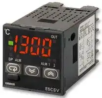
Temperature Controller, E5CSV Series, 24 Vac/dc, Voltage Output
- Manufacturer: OMRON INDUSTRIAL AUTOMATION
- Product type: Temperature Controllers
- Thermocouple Type: T
- Output Voltage Max: 12VDC
- Operating Temperature Max: 55°C
- Operating Temperature Min: -10°C
| Delivery and price | |
|---|---|
| Units per pack | 1 |
| Price | 130.23 € |
| Current stock | 10+ |
| Lead time | 30 days |
**Temperature Controllers E5CSV**

CSM_E5CSV_DS_E_7_5

## **Easy Setting Using DIP Switch and Simple Functions in DIN 48** × **48 mm-size Temperature Controllers**

- Easy setting using DIP switch.

- Models with two alarms added to Series, ideal for temperature alarm applications.

- Universal-input (thermocouple/platinum resistance thermometer) models also available.

- Clearly visible digital display with character height of 13.5 mm.

- Models available with black in addition to white cases.

For the most recent information on models that have been certified for safety standards, refer to your OMRON website.

- RoHS compliant.

Refer to _Safety Precautions for All Temperature Controllers_ .

Refer to _E5CS/E5CSV Operation_ for operating procedures.

## **Model Number Structure**

## ■ **Model Number Legend**

## **Models with Terminal Blocks**

## **E5CSV-** @@@@ **-** @

**1 2 3 4 5**

## **1. Control Outputs**

R: Relay

Q: Voltage for driving SSR

## **2. Alarm Outputs**

Blank: No alarm

1: 1 alarm

**3. Input**

KJ: Thermocouple P: Platinum resistance thermometer

T: Thermocouple/platinum resistance thermometer (universal-input)

## **4. Power Supply Voltage**

Blank: 100 to 240 VAC

D: 24 VAC/VDC

**5. Case Color**

Blank: Black

W: Light gray

- 2: 2 alarms

**Note:** A functional explanation is provided here for illustration, but models are not necessarily available for all possible combinations. Refer to _Ordering Information_ when ordering.

## **Examples**

- Relay control output, without alarm, thermocouple/platinum-resistance thermometer multi input, black case : E5CSV-RT

- **•** Relay control output, one alarm output, platinum resistance thermometer input, black case, light gray case : E5CSV-R1P-W

**1** omron ~~a~~

**E5CSV**

## **Orderin Information g**

## ■ **List of Models**

## **Case Color: Light Gray, Thermocouple or Platinum Resistance Thermometer, Power Supply Voltage: 100 to 240 VAC**

|**Size**|**Type**|**Control**<br>**modes**|**Alarms**|**Outputs**|**Model with**<br>**thermocouple**|**Model with platinum**<br>**resistance**<br>**thermometer**|
|---|---|---|---|---|---|---|
|E5CSV<br>48×48mm|Terminal block|ON/OFF or<br>PID|1|Relay|E5CSV-R1KJ-W|E5CSV-R1P-W|
|||||Voltage (for drivingSSR)|E5CSV-Q1KJ-W|E5CSV-Q1P-W|


## **Case Color: Light Gray, Thermocouple, Power Supply Voltage: 24 VAC/VDC**

|**Size**|**Type**|**Control**<br>**modes**|**Alarms**|**Outputs**|**Model with**<br>**thermocouple**|
|---|---|---|---|---|---|
|E5CSV<br>48×48mm|Terminal block|ON/OFF or<br>PID|1|Relay|E5CSV-R1KJD-W|


## **- Case Color: Light Gray, Universal input, Power Supply Voltage: 100 to 240 VAC**

|**Size**|**Type**|**Control**<br>**modes**|**Alarms**|**Outputs**|**Model with universal-**<br>**input (thermocouple**<br>**or platinum resistance**<br>**thermometer)**|
|---|---|---|---|---|---|
|E5CSV<br>48×48mm|Terminal block|ON/OFF or<br>PID|0|Relay|E5CSV-RT|
|||||Voltage (for drivingSSR)|E5CSV-QT|
||||1|Relay|E5CSV-R1T|
|||||Voltage (for drivingSSR)|E5CSV-Q1T|
||||2 (See note.)|Relay|E5CSV-R2T|
|||||Voltage (for drivingSSR)|E5CSV-Q2T|


**Note:** There is no alarm output 2 mode switch. The default setting for alarm output 2 is for the upper limit alarm mode. To change the setting, change the alarm type for alarm output 2 in initial setting level 5. For details, refer to the _“E5CSV/E5CS-U Digital Temperature Controller User’s Manual”_ (Cat. No. H140-E1-01).

## **- Case Color: Black, Universal input, Power Supply Voltage: 24 VAC/VDC**

|**Size**|**Type**|**Control**<br>**modes**|**Alarms**|**Outputs**|**Model with universal-**<br>**input (thermocouple**<br>**or platinum resistance**<br>**thermometer)**|
|---|---|---|---|---|---|
|E5CSV<br>48×48mm|Terminal block|ON/OFF or<br>PID|0|Relay|E5CSV-RTD|
|||||Voltage (for drivingSSR)|E5CSV-QTD|
||||1|Relay|E5CSV-R1TD|
|||||Voltage (for drivingSSR)|E5CSV-Q1TD|
||||2 (See note.)|Relay|E5CSV-R2TD|
|||||Voltage (for drivingSSR)|E5CSV-Q2TD|


**Note:** There is no alarm output 2 mode switch. The default setting for alarm output 2 is for the upper limit alarm mode. To change the setting, change the alarm type for alarm output 2 in initial setting level 5. For details, refer to the _“E5CSV/E5CS-U Digital Temperature Controller User’s Manual”_ (Cat. No. H140-E1-01).

## ■ **Accessories (Order Separately)**

## **Protective Cover**

|**Type**|**Model**|
|---|---|
|Hard Protective Cover|Y92A-48B|
|**Terminal Cover**<br>**Model**<br>E53-COV10||
|**Model**||
|E53-COV10||


## **Terminal Cover**

## **DIN Track Mounting Adapter**

**==> picture [22 x 6] intentionally omitted <==**

**----- Start of picture text -----**<br>
Model<br>**----- End of picture text -----**<br>


**==> picture [31 x 7] intentionally omitted <==**

**----- Start of picture text -----**<br>
Y92F-52<br>**----- End of picture text -----**<br>


## **Rubber Packing**

## **Model**

**Y92S-29**

**Note:** The Rubber Packing is provided with the Digital Controller.

(For Controllers after the design change scheduled for October 2010)

**Model** E53-COV17

**Note:** The E53-COV10 Terminal Cover cannot be mounted to Controllers that are manufactured after the design change scheduled for October 2010

**==> picture [539 x 34] intentionally omitted <==**

**2**

**E5CSV**

## **S ecifications p**

## ■ **Ratings**

|**Supply voltage**|**Supply voltage**|100 to 240 VAC, 50/60 Hz<br>24 VAC, 50/60 Hz; 24 VDC|
|---|---|---|
|**Operating voltage range**||85% to 110% of rated supply voltage|
|**Power consumption**||100 to 240 VAC: 5 VA<br>24 VAC: 3 VA, 24 VDC: 2 W|
|**Sensor input**||Thermocouple input type:<br>K, J, L<br>Platinum resistance thermometer input type:<br>Pt100, JPt100<br>Universal-input (thermocouple/platinum resistance thermometer) type: K, J, L, T, U, N, R, Pt100, JPt100|
|**Control**<br>**output**|**Relay output**|SPST-NO, 250 VAC, 3A (resistive load)|
||**Voltage output (for driving the SSR)**|12 VDC, 21 mA (with short-circuit protection circuit)|
|**Control method**||ON/OFF or 2-PID (with auto-tuning)|
|**Alarm output**||SPST-NO, 250 VAC, 1A (resistive load)|
|**Setting method**||Digital setting using front panel keys|
|**Indication method**||7-segment digital display (character height: 13.5 mm) and deviation indicators|
|**Other functions**||•Setting change prohibit (key protection)<br>•Input shift<br>•Temperature unit change (°C/°F)<br>•Direct/reverse operation<br>•Temperature range, Sensor switching (K/J/L, Pt100/JPt100)<br>•Switching is performed between a thermocouple and platinum resistance thermometer for universal-input models.<br>•Control period switching<br>•8-mode alarm output<br>•Sensor error detection|
|**Ambient operating temperature**||−10 to 55°C (with no condensation or icing); with 3-year guarantee:−10 to 50°C|
|**Ambient operating humidity**||25% to 85%|
|**Storage temperature**||−25 to 65°C (with no condensation or icing)|


- **Note: 1.** Do not use an inverter output as the power supply. (Refer to _Safety Precautions for All Temperature Controllers_ .) **2.** Models for 24 VAC/DC can also be manufactured.

## ■ **Characteristics**

|**Setting accuracy**|**Setting accuracy**|Thermocouple (See note 1.):<br>(±0.5% of indication value or ±1°C, whichever is greater) ±1 digit max.<br>Platinum resistance thermometer (See note 2.): (±0.5% of indication value or ±1°C, whichever is greater) ±1 digit max.|
|---|---|---|
|**Indication accuracy**<br>**(ambient temperature of 23**°**C)**|||
|**Influence of temperature**||R thermocouple inputs:<br>(±1% of PV or ±10°C, whichever is greater) ±1 digit max.<br>Other thermocouple inputs:<br>(±1% of PV or ±4°C, whichever is greater) ±1 digit max.<br>Platinum resistance thermometer inputs: (±1% of PV or ±2°C, whichever is greater) ±1 digit max.|
|**Influence of voltage**|||
|**Influence of EMS. (at EN61326-1)**|||
|**Hysteresis (for ON/OFF control)**||0.2% FS (0.1% FS for universal-input (thermocouple/platinum resistance thermometer) models)|
|**Proportional band (P)**||1 to 999°C (automatic adjustment using auto-tuning/self-tuning)|
|**Integral time (I)**||1 to 1,999 s (automatic adjustment using auto-tuning/self-tuning|
|**Derivative time (D)**||1 to 1,999 s (automatic adjustment using auto-tuning/self-tuning)|
|**Alarm output range**||Absolute-value alarm: Same as the control range<br>Other:<br>0 to input setting range full scale (°C or°F)<br>Alarm hysteresis:<br>0.2°C or°F (fixed)|
|**Control period**||2/20 s|
|**Sampling period**||500 ms|
|**Insulation resistance**||20 MΩmin. (at 500 VDC)|
|**Dielectric strength**||2,000 VAC, 50/60 Hz for 1 min between current-carryingterminals of different polarity|
|**Vibration**<br>**resistance**|**Malfunction**|10 to 55 Hz, 20 m/s2for 10 min each in X, Y, and Z directions|
||**Destruction**|10 to 55 Hz, 0.75-mm single amplitude for 2 hr each in X, Y, and Z directions|
|**Shock resistance**|**Malfunction**|100 m/s2min., 3 times each in 6 directions|
||**Destruction**|300 m/s2min., 3 times each in 6 directions|
|**Life expectancy**|**Electrical**|100,000 operations min. (relay output models)|
|**Weight**||Approx. 120 g (Controller only)|
|**Degree of protection**||Front panel: Equivalent to IP66; Rear case: IP20; Terminals: IP00|
|**Memory protection**||EEPROM (non-volatile memory) (number of writes: 1,000,000)|
|**EMC**||EMI Radiated:<br>EN 55011 Group 1 Class A<br>EMI Conducted:<br>EN 55011 Group 1 Class A<br>ESD Immunity:<br>EN 61000-4-2: 4 kV contact discharge (level 2)<br>8 kV air discharge (level 3)<br>Radiated Electromagnetic Field Immunity:<br>EN 61000-4-3: 10 V/m (80-1000 MHz, 1.4-2.0 GHz amplitude modulated) (level 3)<br>10 V/m (900 MHz pulse modulated)<br>Conducted Disturbance Immunity:<br>EN 61000-4-6: 3 V (0.15 to 80 MHz) (level 2)<br>Noise Immunity (First Transient Burst Noise): EN 61000-4-4<br>Burst Immunity:<br>2 kV power-line (level 3), 1 kV I/O signal-line (level 3)<br>Surge Immunity:<br>EN 61000-4-5: Power line:<br>Normal mode 1 kV; Common mode 2 kV<br>Output line (relay output): Normal mode 1 kV; Common mode 2 kV<br>Voltage Dip/InterruptingImmunity:<br>EN 61000-4-11 0.5 cycle, 100% (rated voltage)|
|**Approved standards**||UL 61010-1 (listing)<br>CSA C22.2 No.1010-1|
|**Conformed standards**||EN61326-1 (See note 3.), EN61010-1, IEC61010-1<br>VDE 0106 Part 100 (finger protection), when the terminal cover is mounted.|


- **Note: 1.** The following exceptions apply to thermocouples.

   - U, L: ±2 ° C ±1 digit max.

   - R: ±3 ° C ±1 digit max. at 200 ° C or less

   **2.** The following exceptions apply to platinum resistance thermometers. Input set values 0, 1, 2, 3 for E5CSV: 0.5% FS ±1 digit max.

   **3.** Industrial electromagnetic environment (EN/IEC 61326-1 Table 2)

**==> picture [539 x 34] intentionally omitted <==**

**3**

**E5CSV**

## ■ **Temperature Range**

## **Thermocouple Input Models**

**==> picture [506 x 102] intentionally omitted <==**

**----- Start of picture text -----**<br>
Input K J/L<br>999<br>Temperature  1,000<br>900<br>range  800<br>(selected  700 600<br>using switch) 600500 400 500 400 500<br>400 300 300<br>(Default setting: 2) 300200 200 200<br>100<br>0<br>0 0 0 0 0 0 0 0 0 0<br>Setting number 0 1 2 3 4 5 6 7 8 9<br> The shaded value indicates the default<br>Minimum setting unit 1°C 1°C setting status.<br>9 0 1<br>8 2<br>7 3<br>6 5 4<br>**----- End of picture text -----**<br>


## **Platinum Resistance Thermometer Input Models**

|Temperature<br>range<br>(selected<br>using switch)<br>Input<br>500<br>400<br>300<br>200<br>100<br>0<br>−100<br>(Default setting: 3)<br>Setting number<br>Minimum setting unit<br>0<br>1<br>2<br>3<br>4<br>5<br>6<br>7<br>8<br>9<br>|JPt100/Pt100|JPt100/Pt100|JPt100/Pt100|JPt100/Pt100|JPt100/Pt100|JPt100/Pt100|JPt100/Pt100|JPt100/Pt100|JPt100/Pt100|JPt100/Pt100|The shaded value indicates the default<br>setting status.|
|---|---|---|---|---|---|---|---|---|---|---|---|
|||||||||||||
||||||||400||400|||
|||||||300||300||||
||50|50.0|80|99.9|200|||||199.9||
|||0.0||0.0|0|0|0|0|0|0.0||
||−50||−20|||||||||
||0|1|2|3|4|5|6|7|8|9||
||1°C|0.1°C|1°C|0.1°C|1°C|||||0.1°C||


## **- Universal input (Thermocouple/Platinum Resistance Thermometer) Models**

- **Using Thermocouple Sensors, Control Mode Switch 5: OFF**

**==> picture [506 x 148] intentionally omitted <==**

**----- Start of picture text -----**<br>
Input K J L T U N R<br>1,700 1,700<br>1,600<br>1,500<br>Temperature  1,4001,300 1,300 1,300<br>range (selected  1,2001,1001,000 850 850<br>using switch) 900<br>800<br>700<br>600<br>(Default setting: 0) 500 400 400<br>400<br>300 199.9 199.9 199.9<br>200<br>100<br>−1000 −99 0.0 −99 0.0 −99 −99 0.0 −99 −99 0<br>Setting number 0 1 2 3 4 5 6 7 8 9<br>Minimum setting unit 1°C 0.1°C 1°C 0.1°C 1°C 0.1°C 1°C  The shaded value indicates the default setting status.<br>9 0 1<br>8 2<br>7 3<br>6 5 4<br>**----- End of picture text -----**<br>


- **Using Platinum Resistance Thermometers, Control Mode Switch 5: ON**

|Input<br>Temperature<br>range<br>(selected<br>using switch)<br>1,000<br>900<br>800<br>700<br>600<br>500<br>400<br>300<br>200<br>100<br>0<br>−100<br>(Default setting: 0)<br>Setting number<br>Minimum setting unit<br>0<br>1<br>2<br>3<br>4<br>5<br>6<br>7<br>8<br>9<br>|Pt100|Pt100|Pt100|Pt100|Pt100|Pt100|Pt100|JPt100|JPt100|JPt100|JPt100|JPt100|The shaded value indicates the default<br>setting status.|
|---|---|---|---|---|---|---|---|---|---|---|---|---|---|
||850|||||||||||||
|||||||||||||||
|||||||||||||||
||||||||400|500||||400||
|||||199.9||200|||199.9||200|||
||||||99|||||99||||
|||||||||||||||
|||||0.0||0|0||0.0||0|0||
||−99||||−99|||−99||−99||||
||0|||1|2|3|4|5|6|7|8|9||
||1°C|||0.1°C|1°C||||0.1°C|1°C||||


**==> picture [539 x 34] intentionally omitted <==**

**4**

**E5CSV**

## **External Connection Dia ram g**

**==> picture [229 x 212] intentionally omitted <==**

**----- Start of picture text -----**<br>
Voltage output<br>models  Relay output  Alarm output<br>(See note 1.) models<br>Voltage output Relay output<br>1 1 6<br>12 VDC,<br>21 mA<br>2 2 7 Alarm output 2 (See note 3<br>A Alarm output 1 (See note 3<br>3 3 8<br>B<br>4 4 9<br>100 to 240 VAC, 50/60 Hz<br>(24 VAC/VDC)<br>B (See note 2.)<br>5 5 10<br>Platinum resistance  Thermocouple<br>thermometer input input<br>Thermocouple/<br>platinum resistance thermometer universal-input<br>**----- End of picture text -----**<br>


- **Note: 1.** The voltage output (12 VDC, 21 mA) is not electrically isolated from the internal circuits. When using a grounding thermocouple, do not connect output terminals 1 or 2 to ground. Otherwise, unwanted current paths will cause measurement errors.

   **2.** Models with 100 to 240 VAC and 24 VAC/VDC are separate. Models using 24 VDC have no polarity.

   **3.** The number of alarm outputs depends on the model.

## **Nomenclature**

## **E5CSV Models with Terminal Blocks**

**==> picture [282 x 104] intentionally omitted <==**

**----- Start of picture text -----**<br>
Output indicator<br>Deviation indicators Temperature display<br>Mode indicators Alarm indicators<br>Mode Key Up Key<br>Lock Release Key<br>Down Key<br>**----- End of picture text -----**<br>


**==> picture [539 x 34] intentionally omitted <==**

**5**

**E5CSV**

## **Dimensions**

**Note:** All units are in millimeters unless otherwise indicated.

## ■ **Controller**

**==> picture [506 x 238] intentionally omitted <==**

**----- Start of picture text -----**<br>
E5CSV<br>Panel Cutout Dimensions<br>84<br>4 8×48 6 78 45+0.6  0<br>L<br>45 [+0.6  ] 0 45+0.6  0<br>44.8×44.8<br>60 min. L = (48 × N−2.5)+10<br>Mounting side-by-side<br>(group mounting of N Controllers)<br>Note:  Terminals cannot be removed.<br>E5CSV + Adapter for Flush Mounting<br>(Provided) Adapter for flush mounting Panel Y92F-30 Adapter for flush mounting<br>58<br>Tightening<br>48 screws<br>7.5 76.5<br>**----- End of picture text -----**<br>


**==> picture [162 x 21] intentionally omitted <==**

**----- Start of picture text -----**<br>
E5CSV + Adapter for Flush Mounting<br>(Provided)<br>**----- End of picture text -----**<br>


**Note: 1.** The recommended panel thickness is 1 to 4 mm. **2.** Group mounting is possible in one direction only.

## **DIN Track Mounting Adapter**

**Y92F-52 Note:** This Adapter cannot be used together with the Terminal Cover. Remove the Terminal Cover to use the Adapter.

**==> picture [385 x 190] intentionally omitted <==**

**----- Start of picture text -----**<br>
61<br>3.5<br>50 38<br>Mounted to E5CSV<br>48<br>100.5<br>**----- End of picture text -----**<br>


**Mounted to E5CSV**

**==> picture [539 x 34] intentionally omitted <==**

**6**

**E5CSV**

## ■ **Accessories (Order Separately)**

## **Hard Protective Cover**

The Y92A-48B Protective Cover (hard type) is available for the following applications.

**==> picture [66 x 52] intentionally omitted <==**

**----- Start of picture text -----**<br>
bas °C il i;<br>92A-48B<br>**----- End of picture text -----**<br>


- To protect the set from dust and dirt.

- To prevent the panel from being accidentally touched causing displacement of set values.

- To provide effective protection against water droplets.

## **Terminal Cover**

## **Rubber Packing**

**E53-COV10**

**Y92S-29 (for DIN48** × **48)**

~~=~~ 48 48.8 ~~HE~~ 22 9.1

Order the Rubber Packing separately if it becomes lost or damaged. The Rubber Packing can be used to achieve an IP66 degree of protection for models with terminal blocks.

(Deterioration, shrinking, or hardening of the rubber packing may occur depending on the operating environment. Therefore, periodic replacement is recommended to ensure the level of waterproofing specified in NEMA4. The time for periodic replacement depends on the operating environment. Be sure to confirm this point at your site. Consider one year a rough standard. OMRON shall not be liable for the level of water resistance if the customer does not perform periodic replacement.)

**E53-COV17** —-, ~~>Re~~ 48 48.8 ‘Te4| [i ~~ial~~ dt || 22 ~~i~~ (For Controllers after the design change scheduled for October 2010) 9.1

The Rubber Packing does not need to be attached if a waterproof structure is not required.

## **Safet Precautions y**

Refer to _Safety Precautions for All Temperature Controllers_ . Refer to _E5CS/E5CSV Operation_ for operating procedures.

ALL DIMENSIONS SHOWN ARE IN MILLIMETERS.

To convert millimeters into inches, multiply by 0.03937. To convert grams into ounces, multiply by 0.03527.

In the interest of product improvement, specifications are subject to change without notice.

**7** omrRONn ~~a~~

## Terms and Conditions Agreement

## Read and understand this catalog.

Please read and understand this catalog before purchasing the products.  Please consult your OMRON representative if you have any questions or comments.

## Warranties.

(a) Exclusive Warranty. Omron’s exclusive warranty is that the Products will be free from defects in materials and workmanship for a period of twelve months from the date of sale by Omron (or such other period expressed in writing by Omron). Omron disclaims all other warranties, express or implied.

(b) Limitations. OMRON MAKES NO WARRANTY OR REPRESENTATION, EXPRESS OR IMPLIED, ABOUT NON-INFRINGEMENT, MERCHANTABILITY OR FITNESS FOR A PARTICULAR PURPOSE OF THE PRODUCTS. BUYER ACKNOWLEDGES THAT IT ALONE HAS DETERMINED THAT THE

PRODUCTS WILL SUITABLY MEET THE REQUIREMENTS OF THEIR INTENDED USE.

Omron further disclaims all warranties and responsibility of any type for claims or expenses based on infringement by the Products or otherwise of any intellectual property right. (c) Buyer Remedy. Omron’s sole obligation hereunder shall be, at Omron’s election, to (i) replace (in the form originally shipped with Buyer responsible for labor charges for removal or replacement thereof) the non-complying Product, (ii) repair the non-complying Product, or (iii) repay or credit Buyer an amount equal to the purchase price of the non-complying Product; provided that in no event shall Omron be responsible for warranty, repair, indemnity or any other claims or expenses regarding the Products unless Omron’s analysis confirms that the Products were properly handled, stored, installed and maintained and not subject to contamination, abuse, misuse or inappropriate modification. Return of any Products by Buyer must be approved in writing by Omron before shipment. Omron Companies shall not be liable for the suitability or unsuitability or the results from the use of Products in combination with any electrical or electronic components, circuits, system assemblies or any other materials or substances or environments. Any advice, recommendations or information given orally or in writing, are not to be construed as an amendment or addition to the above warranty.

See http://www.omron.com/global/ or contact your Omron representative for published information.

## Limitation on Liability; Etc.

OMRON COMPANIES SHALL NOT BE LIABLE FOR SPECIAL, INDIRECT, INCIDENTAL, OR CONSEQUENTIAL DAMAGES, LOSS OF PROFITS OR PRODUCTION OR COMMERCIAL LOSS IN ANY WAY CONNECTED WITH THE PRODUCTS, WHETHER SUCH CLAIM IS BASED IN CONTRACT, WARRANTY, NEGLIGENCE OR STRICT LIABILITY. Further, in no event shall liability of Omron Companies exceed the individual price of the Product on which liability is asserted.

## Suitability of Use.

Omron Companies shall not be responsible for conformity with any standards, codes or regulations which apply to the combination of the Product in the Buyer’s application or use of the Product. At Buyer’s request, Omron will provide applicable third party certification documents identifying ratings and limitations of use which apply to the Product. This information by itself is not sufficient for a complete determination of the suitability of the Product in combination with the end product, machine, system, or other application or use. Buyer shall be solely responsible for determining appropriateness of the particular Product with respect to Buyer’s application, product or system. Buyer shall take application responsibility in all cases.

NEVER USE THE PRODUCT FOR AN APPLICATION INVOLVING SERIOUS RISK TO LIFE OR PROPERTY OR IN LARGE QUANTITIES WITHOUT ENSURING THAT THE SYSTEM AS A WHOLE HAS BEEN DESIGNED TO ADDRESS THE RISKS, AND THAT THE OMRON PRODUCT(S) IS PROPERLY RATED AND INSTALLED FOR THE INTENDED USE WITHIN THE OVERALL EQUIPMENT OR SYSTEM.

## Programmable Products.

Omron Companies shall not be responsible for the user’s programming of a programmable Product, or any consequence thereof.

## Performance Data.

Data presented in Omron Company websites, catalogs and other materials is provided as a guide for the user in determining suitability and does not constitute a warranty. It may represent the result of Omron’s test conditions, and the user must correlate it to actual application requirements. Actual performance is subject to the Omron’s Warranty and Limitations of Liability.

## Change in Specifications.

Product specifications and accessories may be changed at any time based on improvements and other reasons. It is our practice to change part numbers when published ratings or features are changed, or when significant construction changes are made. However, some specifications of the Product may be changed without any notice. When in doubt, special part numbers may be assigned to fix or establish key specifications for your application. Please consult with your Omron’s representative at any time to confirm actual specifications of purchased Product.

## Errors and Omissions.

Information presented by Omron Companies has been checked and is believed to be accurate; however, no responsibility is assumed for clerical, typographical or proofreading errors or omissions.

**In the interest of product improvement, specifications are subject to change without notice.**

## **OMRON Corporation**

## **Industrial Automation Company**

2015.8

**http://www.ia.omron.com/**

(c)Copyright OMRON Corporation 2015 All Right Reserved.
Updated at February 9, 2023
With a legacy spanning over 80 years, Omron Industrial Automation is a globally recognized leader in the manufacture of advanced industrial control and automation components. Renowned for their reliability and engineering excellence, Omron delivers comprehensive solutions that enhance efficiency, machine safety, and precision across a wide range of manufacturing environments. Our extensive portfolio of Omron products is heavily focused on their industry-leading sensing and switching technologies. We offer a vast selection of sensors, excelling specifically in high-performance proximity sensors, light sensors, and temperature sensors. Complementing this range are robust switching solutions, featuring a deep inventory of power relays, solid-state relays, safety relays, and essential relay accessories designed for demanding operational requirements. Beyond sensing and switching, Omron is highly regarded for its precision automation and process control equipment. Our selection features highly accurate temperature controllers, versatile process controllers, and sophisticated panel displays and instrumentation. To support these fundamental systems, we also supply dependable Omron power supplies, notably AC/DC converters, alongside vital connectivity components like DIN rail terminal blocks to ensure secure, efficient, and complete industrial setups.
About Novapart
Novapart is a B2B electronic component broker specialising in stock shortages and cost reduction. We source hard-to-find parts and identify compliant alternatives across a catalogue of 410,000+ components from 500+ manufacturers.
Learn more →Stock Shortage Specialist
When a component is unavailable, discontinued or has an unacceptable lead time, we tap into our network of vetted European and Asian distributors to source what you need — without compromising on quality or traceability.
Request a quote →Compliant Alternatives
We identify pin-to-pin, electrically equivalent substitutes that meet the same certifications (RoHS, AEC-Q100, REACH) as your original specification — validated against datasheets, not just part numbers. Often at a lower cost.
BOM Analysis service →