
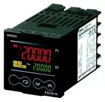


E5CN-HTQ2M-500 100-240 VAC
Temperature Controller, 1/16 DIN, Programmable, ON/OFF & PID Control, -200 °C to 2300 °C, 100-240 V
- Manufacturer: OMRON INDUSTRIAL AUTOMATION
- Product type: Temperature Controllers
- SVHC: To Be Advised
| Delivery and price | |
|---|---|
| Units per pack | 1 |
| Price | 366.27 € |
| Current stock | 10+ |
| Lead time | 30 days |
**Programmable Temperature Controller (Digital Controller) E5CN-HT (48 x 48 mm)**

CSM_E5CN-HT_DS_E_1_10

## **Programmable Controllers Join the Series!**

## **Program up to 256 segments and take advantage of the high cost performance of the new LCD that improves both the field of view and contrast.**

- Set up to 8 programmed patterns with up to 32 segments (steps) each.

- High-resolution display with 5 digits/0.01 ° C display in a compact Controller (48 x 48 mm).

- High-speed sampling cycle of 60 ms.

- High Accuracy Thermocouple/Pt input: ±0.1% of PV Analog input: ±0.1% FS

- Universal inputs on all models (thermocouple, PT, or analog input) to handle various sensors with one Controller.

- A PV/SV-status display function can be set to automatically alternate between displaying the status of the Temperature Controller (auto/ manual, RUN/RESET, and alarms) and the PV or SV.

- Flexible contact outputs with logic operations (AND, OR, and delays) set from the Support Software (CX-Thermo version 4.3). Program settings can be managed.

**==> picture [40 x 14] intentionally omitted <==**

**----- Start of picture text -----**<br>
 48  ×  48 mm<br>E5CN-HT<br>**----- End of picture text -----**<br>


For the most recent information on models that have been certified for safety standards, refer to your OMRON website.

Refer to _Safety Precautions for E5_ @ _N/E5_ @ _N-H/ E5_ @ _N-HT_ . Refer to _Operation for E5_ @ _N/E5_ @ _N-H/ E5_ @ _N-HT_ for ~~PO~~ operating procedures.

E53-CNQ @ -500 in this catalog have been discontinued at the end of March 2018. ~~Po~~

- Preventive maintenance for relays in the Temperature Controller using a Control Output ON/OFF Counter.

## **Main I/O Functions**

**==> picture [484 x 233] intentionally omitted <==**

**----- Start of picture text -----**<br>
Event Inputs  E5CN-HT<br>• None<br>• Two 2-level Display: PV and SV 5-digit Display with high resolution of 0.01°C<br>Universal Sensor Inputs = —_ • Programmable function<br>• Universal thermocouple/Pt/analog<br>Auxiliary Outputs 8 programs × 32 segments<br>   (current/voltage) inputs.  • Two • Auto/manual switching<br>Control Output 2  * • Temperature Controller status display<br>Indication Accuracy<br>• Thermocouple/Pt input: ±0.1% of PV • None • Simple program function<br>• Analog input:  ±0.1% FS • Voltage output • Logic operations<br>  (for driving SSR) • Control output ON/OFF count alarm<br>• PV change rate alarm<br>Sampling Period Control Output 1 • Models also available with RS-485 or<br>• 60 ms<br>• Relay output    RS-232C communications<br>• Voltage output (for driving SSR)<br>• Current output<br>* Orders will not be accepted after<br>• Linear voltage output<br>March 31, 2018.<br>**----- End of picture text -----**<br>


This data sheet is provided as a guideline for selecting products. Be sure to refer to the following user manuals for application precautions ~~FO~~ and other information required for operation before attempting to use the product.

E5CN-HT/E5AN-HT/E5EN-HT Digital Controllers User's Manual Programmable Type (Cat. No. H169) E5CN-HT/E5AN-HT/E5EN-HT Digital Controllers Communications Manual Programmable Type (Cat. No. H170)

**1** omRON ~~a~~

**E5CN-HT**

## **Lineup**

E5CN-HT 1 control output Programmable Terminal block Fully universal input Type 2 control outputs

2 auxiliary outputs

2 auxiliary outputs

**Note:** Models with one control output and models with two control outputs can be used for heating/cooling control.

## **Model Number Structure**

## **Model Number Legend Controllers**

## **E5CN-** @@@ **M** @ **-** @ **-500**

**1 2 3 4 5 6 7**

## **1. Type**

HT: Programmable

## **2. Control Output 1**

R: Relay output

- Q: Voltage output (for driving SSR)

- C: Current output

- V: Linear voltage output

## **3. Auxiliary Outputs**

- 2: Two outputs

## **4. Option 1**

- M: Option Unit can be mounted.

## **5. Power Supply Voltage**

Blank: 100 to 240 VAC

D: 24 VAC/VDC

## **6. Case Color**

Blank: Black

## **7. Terminal Cover**

- -500: With terminal cover

## **Option Units**

## **E53-** @@@@

**1 2 3 4**

## **1. Applicable Controller**

CN: E5CN-HT, E5CN-H or E5CN

## **2. Function 1**

Blank: None

- Q: Control output 2 (voltage output for driving SSR) *

- P: Power supply for sensor

- C: Current output

## **3. Function 2**

Blank: None

H: Heater burnout/SSR failure/Heater overcurrent detection (CT1)

- HH: Heater burnout/SSR failure/Heater overcurrent detection (CT2)

B: Two event inputs

03: RS-485 communications

- H03: Heater burnout/SSR failure/Heater overcurrent detection

(CT1) + RS-485 communications

HB: Heater burnout/SSR failure/Heater overcurrent detection

(CT1) + Two event inputs

HH03: Heater burnout/SSR failure/Heater overcurrent detection

(CT2) + RS-485 communications

- H01: Heater burnout/SSR failure/Heater overcurrent detection

   - (CT1)/RS-232C communications

F: Transfer output

BF: Two event inputs/Transfer output

## **4. Version**

N2: Available only to models released after January 2008

**Note: 1.** Not all combinations of function 1 and function 2 specifications are possible for Option Units (E53- @@@@ ).

**2.** Estimates can be provided for coatings and other specifications that are not given in the datasheet. Ask your OMRON representative for details.

- Orders will not be accepted after March 31, 2018.

**2**

**E5CN-HT**

## **Ordering Information**

## **Controllers**

|**Size**|**Case Color**|**Power supply voltage**|**Auxiliary output**|**Control output 1**|**Model**|
|---|---|---|---|---|---|
|1/16 DIN<br>48×48×78<br>(W×H×D)|Black|100 to 240 VAC|2|Relay output|**E5CN-HTR2M-500**|
|||||Voltage output (for driving SSR)|**E5CN-HTQ2M-500**|
|||||Current output|**E5CN-HTC2M-500**|
|||||Linear voltage output|**E5CN-HTV2M-500**|
|||24 VAC/VDC|2|Relay output|**E5CN-HTR2MD-500**|
|||||Voltage output (for driving SSR)|**E5CN-HTQ2MD-500**|
|||||Current output|**E5CN-HTC2MD-500**|
|||||Linear voltage output|**E5CN-HTV2MD-500**|


## **Option Units**

One of the following Option Units can be mounted to provide the E5CN with additional functions.

|**Functions**|**Functions**|**Functions**|**Functions**|**Functions**|**Functions**|**Model**|
|---|---|---|---|---|---|---|
|Communications<br>RS-485||3-phase heater burnout/SSR failure/<br>Heater overcurrent detection||||**E53-CNHH03N2**|
|||Heater burnout/SSR failure/<br>Heater overcurrent detection|Event inputs|||**E53-CNHBN2**|
|Communications<br>RS-485||||Control output 2<br>(Voltage for driving SSR)||**E53-CNQ03N2***|
|Communications<br>RS-485||Heater burnout/SSR failure/<br>Heater overcurrent detection||||**E53-CNH03N2**|
|Communications<br>RS-485||||||**E53-CN03N2**|
||||Event inputs|||**E53-CNBN2**|
|||Heater burnout/SSR failure/<br>Heater overcurrent detection||Control output 2<br>(Voltage for driving SSR)||**E53-CNQHN2***|
|||3-phase heater burnout/SSR failure/<br>Heater overcurrent detection||Control output 2<br>(Voltage for driving SSR)||**E53-CNQHHN2***|
||||Event inputs|Control output 2<br>(Voltage for driving SSR)||**E53-CNQBN2***|
|||||Control output 2<br>(Voltage for driving SSR)|Transfer Output|**E53-CNQFN2***|
||||Event inputs||Transfer Output|**E53-CNBFN2**|
||Communications<br>RS-232C|||Control output 2<br>(Voltage for driving SSR)||**E53-CNQ01N2***|
||Communications<br>RS-232C|||||**E53-CN01N2**|
||Communications<br>RS-232C|Heater burnout/SSR failure/<br>Heater overcurrent detection||||**E53-CNH01N2**|


**Note:** These Option Units are applicable only to models released after January 2008.

- Orders will not be accepted after March 31, 2018.

## **Accessories (Order Separately) USB-Serial Conversion Cable**

**Model E58-CIFQ1 Terminal Cover Model E53-COV17**

- **Note: 1.** The Terminal Cover comes with the E5CN- @@@ -500 models.

   **2.** The E53-COV10 cannot be used.

## **Waterproof Packing**

## **Model**

## **Y92S-P8**

**Note:** Waterproof Packing is included with the controller only for models with terminal blocks.

## **Current Transformers (CTs)**

|**Hole diameter**|**Model**|
|---|---|
|5.8 dia.|**E54-CT1**|
|12.0 dia.|**E54-CT3**|


## **Adapter**

|**Connectable models**|**Model**|
|---|---|
|Terminal type|**Y92F-45**|
|**Note:**Use this Adapter when the panel has been previously prepared<br>for the E5B@.||


## **DIN Track Mounting Adapter**

|**Model**|**Model**|
|---|---|
|**Y92F-52**||
|**Front cover**||
|**Type**|**Model**|
|Hard Front Cover|**Y92A-48B**|
|Soft Front Cover|**Y92A-48D**|


## **CX-Thermo Support Software**

**Model EST2-2C-MV4 Mounting Adapter Model Y92F-49**

**Note:** This Mounting Adapter is provided with the Digital Temperature Controller.

**3**

**E5CN-HT**

## **Specifications**

## **Ratings**

|**Specifications**<br>**Ratings**|**Specifications**<br>**Ratings**|**E5CN-HT**|
|---|---|---|
|**Power supply voltage**||No D in model number: 100 to 240 VAC, 50/60 Hz<br>D in model number: 24 VAC, 50/60 Hz; 24 VDC|
|**Operating voltage range**||85% to 110% of rated supply voltage|
|**Power consumption**||100 to 240 VAC: 8.5 VA (max.) (E5CN-HTR2 at 100 VAC: 3.0 VA)<br>24 VAC/VDC: 5.5 VA (24 VAC)/3.5 W (24 VDC) (max.) (E5CN-HTR2D at 24 VAC: 2.7 VA)|
|**Sensor input**||Any of the following can be selected (i.e., fully universal input).<br>Thermocouple: K, J, T, E, L, U, N, R, S, B, W, or PL II<br>Platinum resistance thermometer: Pt100 or JPt100<br>Current input: 4 to 20 mA or 0 to 20 mA<br>Voltage input: 1 to 5 V, 0 to 5 V, or 0 to 10 V|
|**Input impedance**||Current input: 150Ωmax., Voltage input: 1 MΩmin. (Use a 1:1 connection when connectingthe ES2-HB-N.)|
|**Control method**||ON/OFF control or 2-PID control (with auto-tuning)|
|**Control**<br>**output**|**Relay output**|SPST-NO, 250 VAC, 3 A (resistive load), electrical life: 100,000 operations, minimum applicable load: 5 V, 10 mA|
||**Current output**|4 to 20 mA DC/0 to 20 mA DC, load: 600Ωmax., resolution: approx. 10,000*|
||**Linear voltage**<br>**output**|0 to 10 VDC (load: 1 kΩmin.), Resolution: Approx. 10,000|
|**Auxiliary**<br>**output**|**Number of outputs**|2 max.|
||**Output**<br>**specifications**|Relay output: SPST-NO, 250 VAC, 3 A (resistive load), electrical life: 100,000 operations, minimum applicable<br>load: 5 V, 10 mA|
|**Event**<br>**input**|**Number of outputs**|2|
||**External contact**<br>**input**<br>**specifications**|Contact input: ON: 1 kΩmax., OFF: 100 kΩmin.|
|||Non-contact input: ON: Residual voltage: 1.5 V max., OFF: Leakage current: 0.1 mA max.|
|||Current flow: Approx. 7 mA per contact|
|**Logic**<br>**opera-**<br>**tions**|**Number of**<br>**operations**|8 max. (Combinations can be made using work bits.)|
||**Operations**|•Logic operation: Any of the following four patterns can be selected. The input status may be inverted.<br>(A and B) or (C and D), (A or C) and (B or D), A or B or C or D, A and B and C and D (A, B,<br>C, and D are four inputs.)<br>•Delay:<br>ON delay or OFF delay for the results of the logic operation given above.<br>Setting time: 0 to 9999 s or 0 to 9999 min<br>•Output inversion: Possible|
||**Outputs**|One work bit per operation|
||**Work bit**<br>**assignments**|Any of the following can be assigned to up to eight work bits (logic operation results): Operation commands<br>(assigned to event inputs)*, auxiliary outputs, or control outputs.<br>* Application is possible with models that do not have event inputs by using an internal assignment.|
|**Transfer**<br>**outputs**|<br>**Number of outputs**|1 max.|
||<br>**Output**<br>**specifications**|Current output: 4 to 20 mA DC, Load: 600Ωmax., Resolution at 4 to 20 mA: Approx. 10,000|
|**RSP input**||Not supported|
|**Setting method**||Digital settingusingfront panel keys|
|**Indication method**||11-segment digital display and individual indicators (7-segments displays also possible)<br>Character height: PV: 11 mm, SV: 6.5 mm|
|**Other functions**||Manual output, heating/cooling control, loop burnout alarm, other alarm functions, heater burnout detection<br>(including SSR failure and heater overcurrent detection), 40% AT, 100% AT, MV limiter, input digital filter,<br>temperature input shift, run/reset, protection functions, control output ON/OFF counter, extraction of square root,<br>MV change rate limit, PV/SV status display, automatic cooling coefficient adjustment, program control functions,<br>etc.|
|**Ambient operating**<br>**temperature**||−10 to 55°C (with no condensation or icing),  for 3-year warranty:−10 to 50°C|
|**Ambient operating humidity**||25% to 85%|
|**Storage temperature**||−25 to 65°C (with no condensation or icing)|


* For models with current outputs, control output 1 can be used as a transfer output.

**4**

**E5CN-HT**

## **Input Ranges**

## **Thermocouple/Platinum Resistance Thermometer/Analog Input (Fully Universal Inputs)**

|**Input type**|**Platinum resistance**<br>**thermometer**|**Platinum resistance**<br>**thermometer**|**Platinum resistance**<br>**thermometer**|**Platinum resistance**<br>**thermometer**|**Platinum resistance**<br>**thermometer**|**Platinum resistance**<br>**thermometer**|**Platinum resistance**<br>**thermometer**|**Platinum resistance**<br>**thermometer**|**Thermocouple**|**Thermocouple**|**Thermocouple**|**Thermocouple**|**Thermocouple**|**Thermocouple**|**Thermocouple**|**Thermocouple**|**Thermocouple**|**Thermocouple**|**Thermocouple**|**Thermocouple**|**Thermocouple**|**Thermocouple**|**Thermocouple**|**Thermocouple**|**Thermocouple**|**Thermocouple**|**Thermocouple**|**Thermocouple**|**Thermocouple**|**Analog**<br>**input**|**Analog**<br>**input**|**Analog**<br>**input**|**Analog**<br>**input**|**Analog**<br>**input**|
|---|---|---|---|---|---|---|---|---|---|---|---|---|---|---|---|---|---|---|---|---|---|---|---|---|---|---|---|---|---|---|---|---|---|---|
|**Name**|**Pt100**||||||**JPt100**||**K**|||||**J**|||**T**|||**E**|**L**|**U**||**N**|**R**|**S**|**B**|**W**|**PL II**|**4 to**<br>**20 mA**|**0 to**<br>**20 mA**|**1 to**<br>**5 V**|**0 to**<br>**5 V**|**0 to**<br>**10 V**|
|**Temperature range (**°**C)**<br>**2300**<br>**1800**<br>**1700**<br>**1600**<br>**1500**<br>**1400**<br>**1300**<br>**1200**<br>**1100**<br>**1000**<br>**900**<br>**800**<br>**700**<br>**600**<br>**500**<br>**400**<br>**300**<br>**200**<br>**100**<br>**0**<br>−**100**<br>−**200**||||||||||||||||||||||||||||2300.0||Usable in the following<br>ranges by scaling:<br>−19999 to 32400,<br>−1999.9 to 3240.0,<br>−199.99 to 324.00, or<br>−19.999 to 32.400|||||
||||||||||||||||||||||||||||1800.0||||||||
||||||||||||||||||||||||||1700.0|1700.0|||||||||
||||||||||||||||||||||||||||||||||||
||||||||||||||||||||||||||||||||||||
||||||||||||||||||||||||||||||||||||
||||||||||1300.0|||||||||||||||1300.0|||||1300.0||||||
||||||||||||||||||||||||||||||||||||
||||||||||||||||||||||||||||||||||||
||||||||||||||||||||||||||||||||||||
||850.0|||||||||||||850.0|||||||850.0||||||||||||||
||||||||||||||||||||||||||||||||||||
||||||||||||||||||||||||||||||||||||
||||||||||||||||||||||||||||||||||||
|||||||||||||||||||||600.0|||||||||||||||
|||||500.0|||500.0|||||500.0|||||||||||||||||||||||
||||||||||||||||400.0||400.0|400.0||||400.0|400.0||||||||||||
||||||||||||||||||||||||||||||||||||
|||||||200.00|||||||200.00|||200.00|||200.00||||||||||||||||
||||||100.0|||100.0|||||||||||||||||||||||||||
||||||||||||||||||||||||||||100.0||||||||
||||||0.0|||0.0|||||||||||||||||0.0|0.0||0.0|0.0||||||
|||||||−50.00||||||−20.0|−50.00|−100.0|−20.0|−50.00|||−50.00||−100.0||||||||||||||
||−200.0|||−199.9|||−199.9||−200.0||||||||−200.0|−199.9||−200.0||−200.0|−199.9|−200.0|||||||||||
|**Setting**<br>**number**|0|||1|2|24|3|4|5|||6|21|7|8|22|9|10|23|11|12|13|14|15|16|17|18|19|20|25|26|27|28|29|


Shaded settings are the default settings.

The applicable standards for the input types are as follows:

K, J, T, E, N, R, S, B: JIS C 1602-1995, IEC 584-1

L: Fe-CuNi, DIN 43710-1985

U: Cu-CuNi, DIN 43710-1985

W: W5Re/W26Re, ASTM E988-1990

JPt100: JIS C 1604-1989, JIS C 1606-1989 Pt100: JIS C 1604-1997, IEC 751

PL II: According to Platinel II electromotive force charts from BASF (previously Engelhard)

**5**

**E5CN-HT**

## **Alarm Outputs**

Each alarm can be independently set to one of the following 13 alarm types. The default is _2: Upper limit_ . Auxiliary outputs are allocated for alarms. ON delays and OFF delays (0 to 999 s) can also be specified.

**Note:** For models with heater burnout, SSR failure, and heater overcurrent detection, alarm 1 will be an OR output of the alarm selected from the following alarm types and the alarms for heater burnout, SSR failure, and heater overcurrent. To output only a heater burnout alarm, SSR failure alarm, and heater overcurrent alarm for alarm 1, set the alarm type to 0 (i.e., no alarm function).

|**Set value**|**Alarm type**|**Alarm output operation**|**Alarm output operation**|**Alarm output operation**|**Alarm output operation**|**Alarm output operation**|**Alarm output operation**|**Alarm output operation**|**Alarm output operation**|**Alarm output operation**|**Description of function**|
|---|---|---|---|---|---|---|---|---|---|---|---|
|||**When alarm value**<br>**X is positive**|||||**When alarm value**<br>**X is negative**|||||
|0|Alarm function OFF|Output OFF|||||||||No alarm|
|1*1|Upper- and lower-limit|ON<br>OFF|||L<br>H||*2||||Set the deviation in the set point by setting the alarm<br>upper limit (H) and alarm lower limit (L).|
|||||||||||||
||||||SP|||||||
|2|Upper-limit|ON<br>OFF|||X||ON<br>OFF||X||Set the upward deviation in the set point by setting<br>the alarm value (X).|
|||||||||||||
||||||SP|||||||
|3|Lower-limit|ON<br>OFF|||X||ON<br>OFF|||X|Set the downward deviation in the set point by setting<br>the alarm value (X).|
|||||||||||||
||||||SP|||||||
|4*1|Upper- and lower-limit range|ON<br>OFF|||L<br>H||*3||||Set the deviation in the set point by setting the alarm<br>upper limit (H) and alarm lower limit (L).|
|||||||||||||
||||||SP|||||||
|5*1|Upper- and lower-limit with<br>standby sequence|ON<br>OFF<br>*5|||L<br>H||*4||||A standby sequence is added to the upper- and<br>lower-limit alarm (1).*6|
|||||||||||||
||||||SP|||||||
|6|Upper-limit with standby sequence|ON<br>OFF|||X||ON<br>OFF||X||A standby sequence is added to the upper-limit alarm<br>(2).*6|
|||||||||||||
||||||SP|||||||
|7|Lower-limit with standby sequence|ON<br>OFF|||X||ON<br>OFF|SP<br>X<br>|||A standby sequence is added to the lower-limit alarm<br>(3).*6|
|||||||||||||
||||||SP|||||||
|8|Absolute-value upper-limit|ON<br>OFF|||X||ON<br>OFF||X||The alarm will turn ON if the process value is larger<br>than the alarm value (X) regardless of the set point.|
|||||||||||||
||||||0|||||||
|9|Absolute-value lower-limit|ON<br>OFF|||X||ON<br>OFF||X||The alarm will turn ON if the process value is smaller<br>than the alarm value (X) regardless of the set point.|
|||||||||||||
|||||0||||||||
|10|Absolute-value upper-limit with<br>standby sequence|ON<br>OFF|||X||||X||A standby sequence is added to the absolute-value<br>upper-limit alarm (8).*6|
||||||||ON<br>OFF|||||
||||||0|||||||
|11|Absolute-value lower-limit with<br>standby sequence|ON<br>OFF|||X||ON<br>OFF||X||A standby sequence is added to the absolute-value<br>lower-limit alarm (9).*6|
|||||||||||||
||||||0|||||||
|12|LBA (alarm 1 type only)|||||---|||||*7|
|13|PV change rate alarm|||||---|||||*8|


*1. With set values 1, 4 and 5, the upper and lower limit values can be set independently for each alarm type, and are expressed as “L” and “H.”

*2. Set value: 1, Upper- and lower-limit alarm

|L<br>H<br>H < 0, L > 0<br>⏐H⏐<⏐L⏐<br>SP<br>Case 1|L<br>H<br>H > 0, L < 0<br>⏐H⏐>⏐L⏐<br>SP<br>Case 2|L<br>H<br>H < 0, L < 0<br>SP<br>L<br>H<br>H < 0, L > 0<br>⏐H⏐ ≥ ⏐L⏐<br>SP<br>L<br>H<br>H > 0, L < 0<br>⏐H⏐ ≤ ⏐L⏐<br>SP<br>Case 3 (Always ON)|
|---|---|---|


*3. Set value: 4, Upper- and lower-limit range

*5. Set value: 5, Upper- and lower-limit with standby sequence Always OFF when the upper-limit and lower-limit hysteresis overlaps.

- *6. Refer to the _E5CN-HT/E5AN-HT/E5EN-HT Digital Controllers User's Manual_ (Cat. No. H169) for information on the operation of the standby sequence.

- *7. Refer to the _E5CN-HT/E5AN-HT/E5EN-HT Digital Controllers User's Manual_ (Cat. No. H169) for information on the loop burnout alarm (LBA).

- *8. Refer to the _E5CN-HT/E5AN-HT/E5EN-HT Digital Controllers User's Manual_ (Cat. No. H169) for information on the PV change rate alarm.

|L<br>H SP<br>Case 1<br>H < 0, L > 0<br>⏐H⏐<⏐L⏐|L<br>H<br>SP<br>Case 2<br>H > 0, L < 0<br>⏐H⏐>⏐L⏐|L<br>H<br>SP<br>L<br>L<br>H<br>SP<br>H<br>SP<br>Case 3 (Always OFF)<br>H < 0, L < 0<br>H < 0, L > 0<br>⏐H⏐ ≥ ⏐L⏐<br>H > 0, L < 0<br>⏐H⏐ ≤ ⏐L⏐|
|---|---|---|


- *4. Set value: 5, Upper- and lower-limit with standby sequence For Upper- and Lower-Limit Alarm Described Above

**•** Case 1 and 2 Always OFF when the upper-limit and lower-limit hysteresis overlaps.

- Case 3: Always OFF

**6**

**E5CN-HT**

## **Characteristics**

|**Characteristics**|**Characteristics**||
|---|---|---|
|**Indication accuracy**||Thermocouple: (±0.1% of indicated value or±1°C, whichever is greater)±1 digit max.*1<br>Platinum resistance thermometer: (±0.1% of indicated value or±0.5°C, whichever is greater)±1 digit max.<br>Analog input:±0.1% FS±1 digit max.<br>CT input:±5% FS±1 digit max.|
|**Transfer output accuracy**||±0.3% FS max.|
|**Influence of temperature**<br>***2**||Thermocouple input (R, S, B, W, PLII): (±1% of PV or±10°C, whichever is greater)±1 digit max.<br>Other thermocouple input: (±1% of PV or±4°C, whichever is greater)±1 digit max.*3<br>Platinum resistance thermometer: (±1% of PV or±2°C, whichever is greater)±1 digit max.<br>Analog input: (±1%FS)±1 digit max.|
|**Influence of voltage *2**|||
|**Influence of EMS.**<br>**(at EN 61326-1)**|||
|**Input sampling period**||60 ms|
|**Hysteresis**||Temperature input: 0.1 to 3240.0°C or°F (in units of 0.1°C or°F)<br>Analoginput: 0.01% to 99.99% FS (in units of 0.01% FS)|
|**Proportional band (P)**||Temperature input: 0.1 to 3240.0°C or°F (in units of 0.1°C or°F)<br>Analoginput: 0.1% to 999.9% FS (in units of 0.1% FS)|
|**Integral time (I)**||0.0 to 3240.0 s (in units of 0.1 s)|
|**Derivative time (D)**||0.0 to 3240.0 s (in units of 0.1 s)|
|**Control period**||0.5, 1 to 99 s (in units of 1 s)|
|**Manual reset value**||0.0 to 100.0% (in units of 0.1%)|
|**Alarm setting range**||−19999 to 32400 (decimal point position depends on input type)|
|**Affect of signal source**<br>**resistance**||Thermocouple: 0.1°C/Ωmax. (100Ωmax.)<br>Platinum resistance thermometer: 0.1°C/Ωmax. (10Ωmax.)|
|**Insulation resistance**||20 MΩmin. (at 500 VDC)|
|**Dielectric strength**||2,300 VAC, 50 or 60 Hz for 1 min (between terminals with different charge)|
|**Vibration**<br>**resistance**|**Malfunction**|10 to 55 Hz, 20 m/s2for 10 min each in X, Y, and Z directions|
||**Destruction**|10 to 55 Hz, 0.75-mm single amplitude for 2 hrs each in X, Y, and Z directions|
|**Shock**<br>**resistance**|**Malfunction**|100 m/s2, 3 times each in X, Y, and Z directions|
||**Destruction**|300 m/s2, 3 times each in X, Y, and Z directions|
|**Weight**||Controller: Approx. 150g, MountingBracket: Approx. 10g|
|**Degree of protection**||Front panel: IP66, Rear case: IP20, Terminals: IP00|
|**Memory protection**||Non-volatile memory (number of writes: 1,000,000 times)|
|**Setup Tool**||CX-Thermo version 4.3 or higher|
|**Setup Tool port**||Provided on the bottom of the E5CN-HT. Use this port to connect a computer to the E5CN-HT.<br>An E58-CIFQ1 USB-Serial Conversion Cable is required to connect the computer to the E5CN-HT.*4|
|**Standards**|**Approved**<br>**standards**|UL 61010-1, CSA C22.2 No. 1010-1|
||**Conformed**<br>**standards**|EN 61010-1 (IEC 61010-1): Pollution level 2, overcurrent category II|
|**EMC**||EMI:<br>EN 61326-1*5<br>Radiated Interference Electromagnetic Field Strength: EN 55011 Group 1, class A<br>Noise Terminal Voltage:<br>EN 55011 Group 1, class A<br>EMS:<br>EN 61326-1*5<br>ESD Immunity:<br>EN 61000-4-2<br>Electromagnetic Field Immunity:<br>EN 61000-4-3<br>Burst Noise Immunity:<br>EN 61000-4-4<br>Conducted Disturbance Immunity:<br>EN 61000-4-6<br>Surge Immunity:<br>EN 61000-4-5<br>Power Frequency Magnetic Field Immunity:<br>EN 61000-4-8<br>Voltage Dip/InterruptingImmunity:<br>EN 61000-4-11|


*1. The indication accuracy of K thermocouples in the − 200 to 1300 ° C range, T and N thermocouples at a temperature of − 100 ° C max., and U and L thermocouples at any temperatures is ± 2 ° C ± 1 digit max. The indication accuracy of the B thermocouple at a temperature of 400 ° C max. is not specified. The indication accuracy of B thermocouples in the 400 to 800 ° C range is ± 3 ° C max. The indication accuracy of the R and S thermocouples at a temperature of 200 ° C max. is ± 3 ° C ± 1 digit max. The indication accuracy of W thermocouples is ± 0.3 of PV or ± 3 ° C, whichever is greater, ± 1 digit max. The indication accuracy of PL II thermocouples is ± 0.3 of PV or ± 2 ° C, whichever is greater, ± 1 digit max.

*2. Ambient temperature: − 10 ° C to 23 ° C to 55 ° C, Voltage range: − 15% to 10% of rated voltage

*3. K thermocouple at − 100 ° C max.: ± 10 ° C max.

*4. External communications (RS-232C or RS-485) and cable communications for the Setup Tool can be used at the same time.

*5. Industrial electromagnetic environment (EN/IEC 61326-1 Table 2)

**7**

**E5CN-HT**

## **Program Control**

|**Program Control**|||
|---|---|---|
|**Number of programs (patterns)**|8||
|**Number of segments (steps)**|32||
|**Segment setting method**|Time setting(Segment set with set point and time.)||
||Gradient setting(Segment type with set point,gradient, and time.)||
|**Segment times**|0 h 0 min to 99 h 59 min||
||0 min 0 s to 99 min 59 s||
|**Alarm setting**|Set separatelyfor each program.||
|**Reset operation**|Select either stoppingcontrol or fixed SP operation.||
|**Startup operation**|Select continuing, resetting, manual operation, or run mode.||
|**PID sets**|Number of sets|8|
||Settingmethod|Set separatelyfor each program (automatic PIDgroup selection also supported).|
|**Alarm SP function**|Select from ramp SP and target SP.||
|**Program status control**|Segment operation|Advance, hold|
||Program operation|Program repetitions and program links|
|**Wait operation**|Wait method|Waitingat segment ends|
||Wait width setting|Same wait width settingfor all programs|
|**Time signals**|Number of outputs|2|
||Number of ON/OFF<br>Operations|1 each per output|
||Settingmethod|Set separately for each program.|
|**Program status output**|Program end output (pulse width can be set), run output, stage output||
|**Program startup operation**|PV start|Select from segment 1 set point, slope-priorityPV start|
||Standby|0 h 0 min to 99 h 59 min|
|||0 day0 h to 99 day23h|
|**Operation end operation**|Select from resetting, continuingcontrol at final set point, and fixed SP control.||
|**Program SP shift**|Same program SP shift for all programs||


**8**

**E5CN-HT**

## **USB-Serial Conversion Cable**

|**Applicable OS**|Windows XP/Vista/7/8|
|---|---|
|**Applicable software**|CX-Thermo version 4 or higher|
|**Applicable models**|E5AN/E5EN/E5CN/E5CN-U/<br>E5AN-H/E5EN-H/E5CN-H/E5AN-<br>HT/E5EN-HT/E5CN-HT|
|**USB interface standard**|Conforms to USB Specification 1.1.|
|**DTE speed**|38400 bps|
|**Connector specifications**|Computer: USB (type A plug)<br>Temperature Controller: Setup Tool<br>port (on bottom of Controller)|
|**Power supply**|Bus power (Supplied from USB<br>host controller.)|
|**Power supply voltage**|5 VDC|
|**Current consumption**|70 mA|
|**Ambient operating**<br>**temperature**|0 to 55°C (with no condensation or<br>icing)|
|**Ambient operating humidity**|10% to 80%|
|**Storage temperature**|−20 to 60°C (with no condensation<br>or icing)|
|**Storage humidity**|10% to 80%|
|**Altitude**|2,000 m max.|
|**Weight**|Approx. 100g|


**Note:** A driver must be installed in the personal computer. Refer to installation information in the operation manual for the Conversion Cable.

## **Communications Specifications**

|**Transmission line**<br>**connection method**|RS-485: Multipoint<br>RS-232C: Point-to-point|
|---|---|
|**Communications**|RS-485 (two-wire, half duplex)/RS-232C|
|**Synchronization**<br>**method**|Start-stop synchronization|
|**Protocol**|CompoWay/F or Modbus|
|**Baud rate**|1200, 2400, 4800, 9600, 19200, 38400, or<br>57600 bps|
|**Transmission code**|ASCII (CompoWay/F, SYSWAY)<br>RTU (Modbus)|
|**Data bit length***|7 or 8 bits|
|**Stop bit length***|1 or 2 bits|
|**Error detection**|Vertical parity (none, even, odd)<br>Block check character (BCC) with<br>CompoWay/F or CRC-16 Modbus|
|**Flow control**|None|
|**Interface**|RS-485, RS-232C|
|**Retry function**|None|
|**Communications**<br>**buffer**|217 bytes|
|**Communications**<br>**response wait time**|0 to 99 ms<br>Default: 20 ms|


* The baud rate, data bit length, stop bit length, and vertical parity can be individually set using the Communications Setting Level.

## **Current Transformer (Order Separately) Ratings**

|**Ratings**||
|---|---|
|**Dielectric strength**|1,000 VAC for 1 min|
|**Vibration resistance**|50 Hz, 98 m/s2|
|**Weight**|E54-CT1: Approx. 11.5 g,<br>E54-CT3: Approx. 50g|
|**Accessories (E54-CT3 only)**|Armatures (2)<br>Plugs (2)|


## **Heater Burnout Alarms, SSR Failure Alarms, and Heater Overcurrent Alarms**

|**CT input (for heater**<br>**current detection)**|Models with detection for single-<br>phase heaters: One input<br>Models with detection for single-<br>phase or three-phase heaters: Two<br>inputs|
|---|---|
|**Maximum heater current**|50 A AC|
|**Input current indication**<br>**accuracy**|±5% FS±1 digit max.|
|**Heater burnout alarm**<br>**setting range *1**|0.1 to 49.9 A (in units of 0.1 A)<br>Minimum detection ON time: 100 ms|
|**SSR failure alarm setting**<br>**range *2**|0.1 to 49.9 A (in units of 0.1 A)<br>Minimum detection OFF time: 100 ms|
|**Heater overcurrent alarm**<br>**setting range *3**|0.1 to 49.9 A (in units of 0.1 A)<br>Minimum detection ON time: 100 ms|


- *1. For heater burnout alarms, the heater current will be measured when the control output is ON, and the output assigned to the alarm 1 function will turn ON if the heater current is lower than the set value (i.e., heater burnout detection current value).

- *2. For SSR failure alarms, the heater current will be measured when the control output is OFF, and the output assigned to the alarm 1 function will turn ON if the heater current is higher than the set value (i.e., SSR failure detection current value).

- *3. For heater overcurrent alarms, the heater current will be measured when the control output is ON, and the output assigned to the alarm 1 function will turn ON if the heater current is higher than the set value (i.e., heater overcurrent detection current value).

## **Electrical Life Expectancy Curve for Relays (Reference Values)**

**==> picture [159 x 155] intentionally omitted <==**

**----- Start of picture text -----**<br>
500<br>300<br>100<br>50<br>30<br>10<br>5 E5CN-HT<br>3 250 VAC, 30 VDC<br>(resistive load)<br>cosφ = 1<br>1<br>0 1 2 3 4 5 6<br>Switching current (A)<br>4) 10<br>×<br>No. of operations (<br>**----- End of picture text -----**<br>


**9**

**E5CN-HT**

## **External Connections**

- A voltage output (control output, for driving SSR) is not electrically insulated from the internal circuits. When using a grounding thermocouple, do not connect any of the control output terminals to ground. If the control output terminals are connected to ground, errors will occur in the measured temperature values as a result of leakage current.

## **Controllers**

**==> picture [501 x 613] intentionally omitted <==**

**----- Start of picture text -----**<br>
|||||||||||
|---|---|---|---|---|---|---|---|---|---|
|The Temperature Controller is set for a K-type|
|thermocouple (input type = 5) by default. An input error|
|Control output 1|(s.err) will occur if the input type setting does not agree|
|Relay output|with the temperature sensor. Check the input type.|
|250 VAC, 3 A|
|Auxiliary outputs|Auxiliary outputs (relay outputs)|
|(resistive load)|
|(relay outputs)|250 VAC, 3 A|
|Voltage output|1|11|6|(resistive load)|
|(for driving SSR)|Control output 1|Auxiliary output 2|
|12 VDC, 21 mA|2|12|7|A heater burnout alarm, SSR|
|Linear voltage output0 to 10 VAC|DO NOTUSE|DO NOTUSE|A|3|13|8|Auxiliary output 1|failure, heater overcurrent alarm, or input alarm is sent to the|
|Load 1 kCurrent outputΩ min.|mA|B|4|14|9|output to which the alarm 1 function is assigned.|
|0 to 20 mA DC|V|B|Input power supply|• 100 to 240 VAC|
|4 to 20 mA DC|DO NOT|5|15|10|
|USE|• 24 VAC/VDC (no polarity)|
|Load 600 Ω max.|
|Option Units|
|E53-CNBN2|E53-CNQBN2 *|E53-CNHBN2|E53-CNBFN2|
|Event Inputs|Event Inputs and|Event Inputs|Event Inputs and|
|Control Output 2|and CT|Transfer Output|
|11|11|11|11|
|12|12|12|12|
|EV1|EV1|EV1|EV1|
|13|13|13|13|
|EV2|EV2|EV2|EV2|
|DO NOT|14|14|14|14|
|USE|Control output 2|4 to 20 mA DC|
|DO NOT|15|12 VDC 21 mA|15|CT1|15|Transfer output|15|(Load 600 Ω max.)|
|USE|
|E53-CNQHHN2 *|E53-CNQFN2 *|E53-CN01N2|E53-CNH01N2|E53-CNQ01N2 *|
|Control Output 2|Control Output 2 and|Communications|Communications|Communications (RS-232)|
|and CT2|Transfer Output|(RS-232)|(RS-232) and CT|and Control Output 2|
|RS-232C|RS-232C|RS-232C|
|SD|SD|SD|
|11|11|11|11|11|
|Control output 2|Control output 2|
|12 VDC 21 mA|12 VDC 21 mA|RD|RD|RD|
|12|12|12|12|12|
|DO NOT|SG|SG|SG|
|13|13|13|13|13|
|USE|
|CT2|14|14|DO NOT|14|14|14|
|CT1|15|Transfer output 15|4 to 20 mA DC(Load 600 Ω|USEDO NOT|15|CT1|15|Control output 212 VDC 21 mA|15|
|max.)|USE|
|E53-CN03N2|E53-CNQ03N2 *|E53-CNH03N2|E53-CNHH03N2|E53-CNQHN2 *|
|Communications|Communications (RS-485)|Communications|Communications|Control Output 2|
|(RS-485)|and Control Output 2|(RS-485) and CT|(RS-485) and CT2|and CT|
|B (+)|11|B (+)|11|B (+)|11|B (+)|11|Control output 2|11|
|RS-485|RS-485|RS-485|RS-485|12 VDC 21 mA|
|−|12|−|12|−|12|−|12|12|
|A (|)|A (|)|A (|)|A (|)|
|DO NOTUSE|13|DO NOTUSE|13|DO NOTUSE|13|13|DO NOTUSE|13|
|DO NOT|14|14|14|CT2|14|14|
|USEDO NOT|15|Control output 212 VDC 21 mA|15|CT1|15|CT1|15|CT1|15|
|USE|

**----- End of picture text -----**<br>


**Note:** Wire all voltage input terminals correctly. The Controller may fail if voltage input terminals are wired incorrectly. * Orders will not be accepted after March 31, 2018.

**10**

**E5CN-HT**

**Isolation/Insulation Block Diagrams**

**==> picture [504 x 520] intentionally omitted <==**

**----- Start of picture text -----**<br>
Transfer output<br>Temperature input/Analog input/CT input/Voltage pulse output<br>Power  Communications/Event inputs<br>supply Linear current output/Linear voltage output<br>Relay output<br>==Ce Auxiliary output 1, 2<br>: Reinforced insulation : Functional insulation<br>LC oS<br>Nomenclature<br>E5CN-HT<br>Temperature unit<br>No. 1 display<br>CS Operation indicators<br>TE O a —<br>No. 2 display<br>Level Key Up Key<br>O28) ©67R#<br>L259 Mode Key Down Key  |<br>Dimensions (Unit: mm)<br>E5CN-HT<br>Panel Cutout<br>91<br>6 78 Mounted Separately (48 × number of units Group Mounted− 2.5) [+1.0 ] 0<br>48 × 48 1.5<br>45 [+0.6 ] 0<br>i — ae ——<br>58 44.8 × 44.8 48.8<br>60 min. Group mounting does not<br>allow waterproofing.<br>•  Recommended panel thickness is 1 to<br>Waterproof Packing Mounting Adapter Terminal Cover 45 [+0.6 ] 0   •  Group mounting is not possible in the 5 mm.<br>(Accessory, Y92S-P8 (Accessory, Y92F-49 (E53-COV17) vertical direction. (Maintain the specified<br> (also available for ordering separately))  (also available for ordering separately)) (Accessory) a 45 [+0.6 ] 0   •  To mount the Controller so that it is mounting space between Controllers.)waterproof, insert the waterproof packing<br>onto the Controller.<br>•  When two or more Controllers are mounted,<br>make sure that the surrounding<br>Note:  The terminal block cannot be removed. temperature does not exceed the allowable<br>operating temperature specified in the<br>specifications.<br>**----- End of picture text -----**<br>


## **Nomenclature**

## **E5CN-HT**

## **Dimensions**

**(Unit: mm)**

**==> picture [40 x 8] intentionally omitted <==**

**----- Start of picture text -----**<br>
E5CN-HT<br>**----- End of picture text -----**<br>


## **Accessories (Order Separately)**

## **USB-Serial Conversion Cable**

**E58-CIFQ1**

**==> picture [354 x 54] intentionally omitted <==**

**----- Start of picture text -----**<br>
(2,100)<br>250 LED indicator  1,765<br>(SD)<br>USB connector (type A plug) Serial connector<br>LED indicator (RD)<br>**----- End of picture text -----**<br>


**11** omrRon ~~a~~

**E5CN-HT**

## **Terminal Cover**

## **E53-COV17**

**==> picture [151 x 183] intentionally omitted <==**

**----- Start of picture text -----**<br>
Note:  The E53-COV10<br>can not be used.<br>48<br>48.8<br>22<br>9.1<br>**----- End of picture text -----**<br>


## **Waterproof Packing**

## **Y92S-P8 (for DIN 48** × **48)**

Order the Waterproof Packing separately if it becomes lost or damaged.

The Waterproof Packing can be used to achieve an IP66 degree of protection.

(Deterioration, shrinking, or hardening of the waterproof packing may occur depending on the operating environment. Therefore, periodic replacement is recommended to ensure the level of waterproofing specified in IP66. The time for periodic replacement depends on the operating environment. Be sure to confirm this point at your site. Consider one year a rough standard. OMRON shall not be liable for the level of water resistance if the customer does not perform periodic replacement.)

The Waterproof Packing does not need to be attached if a waterproof structure is not required.

## **Current Transformers**

## **E54-CT1**

**==> picture [145 x 128] intentionally omitted <==**

**----- Start of picture text -----**<br>
21<br>2.8<br>15<br>5.8 dia.<br>7.5<br>25 3<br>10.5<br>40<br>Two, 3.5 dia.<br>10<br>30<br>**----- End of picture text -----**<br>


## **E54-CT3**

**==> picture [146 x 132] intentionally omitted <==**

**----- Start of picture text -----**<br>
2.36 dia.<br>30<br>12 dia.<br>9<br>40 × 40<br>Two, M3 (depth: 4)<br>15<br>30<br>**----- End of picture text -----**<br>


## **E54-CT3 Accessory**

**==> picture [203 x 9] intentionally omitted <==**

**----- Start of picture text -----**<br>
• Armature Connection Example<br>**----- End of picture text -----**<br>


**==> picture [228 x 121] intentionally omitted <==**

**----- Start of picture text -----**<br>
Armature<br>Approx. 3 dia. Plug<br>Lead<br>18<br>• Plug<br>Approx. 6 dia.<br>(22)<br>**----- End of picture text -----**<br>


**==> picture [42 x 33] intentionally omitted <==**

## **E54-CT1 Thru-current (Io) vs. Output Voltage (Eo) (Reference Values)**

Maximum continuous heater current: 50 A (50/60 Hz) Number of windings: 400±2

Winding resistance: 18±2 Ω

**==> picture [163 x 397] intentionally omitted <==**

**----- Start of picture text -----**<br>
100 V<br>50 Hz<br>10 ∞<br>1 kΩ Distortion<br>factor 10%<br>1<br>3%<br>1%<br>100 mV<br>10 100 Ω<br>1 RL = 10 Ω<br>100 μV<br>10<br>1 10 100 mA 1 10 100 1,000 A<br>Thru-current (Io) A (r.m.s.)<br>E54-CT3<br>Thru-current (Io) vs. Output Voltage<br>(Eo) (Reference Values)<br>Maximum continuous heater current: 120 A (50/60 Hz)<br>(Maximum continuous heater current for an OMRON<br>Temperature Controller is 50 A.)<br>Number of windings: 400±2±22<br>Winding resistance: 8±0.8 Ω±0.8 Ω0.8 ΩΩ<br>100 V<br>50 Hz Distor-<br>∞ tion<br>10 1 kΩ factor<br>10%<br>500 Ω 3%<br>1 1%<br>100 mV<br>100 Ω<br>50  Ω<br>10<br>R L  = 10 Ω<br>1<br>100 μV<br>10<br>1 10 100 mA 1 10 100 1,000 A<br>Thru-current (Io) A (r.m.s.)<br>Output voltage (Eo) V (r.m.s.)<br>Output voltage (Eo) V (r.m.s.)<br>**----- End of picture text -----**<br>


## **E54-CT3**

## **Thru-current (Io) vs. Output Voltage (Eo) (Reference Values)**

Maximum continuous heater current: 120 A (50/60 Hz) (Maximum continuous heater current for an OMRON Temperature Controller is 50 A.) Number of windings: 400±2±22

Winding resistance: 8±0.8 Ω±0.8 Ω0.8 ΩΩ

**12**

**E5CN-HT**

## **Adapter**

**Y92F-45 Note: 1.** Use this Adapter when the panel has already been prepared for the E5B @ . **2.** The Adapter is available only in black.

**==> picture [265 x 296] intentionally omitted <==**

**----- Start of picture text -----**<br>
Fixture (Accessory)<br>4.7 76<br>69.6 to 77.6<br>72  ×  72<br>67  ×  67 87<br>Panel (1 to 8 mm)<br>72  ×  72<br>48  ×  48<br>2.2 4.7<br>77.3 (to back of E5CN-HT)<br>**----- End of picture text -----**<br>


**Mounted to E5CN-HT**

**==> picture [65 x 91] intentionally omitted <==**

## **DIN Track Mounting Adapter**

**Y92F-52 Note:** This Adapter cannot be used together with the Terminal Cover. Remove the Terminal Cover to use the Adapter.

**==> picture [168 x 83] intentionally omitted <==**

**----- Start of picture text -----**<br>
61<br>3.5<br>50 38<br>**----- End of picture text -----**<br>


**Mounted to E5CN-HT**

**==> picture [136 x 78] intentionally omitted <==**

**----- Start of picture text -----**<br>
48<br>100.5<br>**----- End of picture text -----**<br>


**13**

## Terms and Conditions Agreement

## Read and understand this catalog.

Please read and understand this catalog before purchasing the products.  Please consult your OMRON representative if you have any questions or comments.

## Warranties.

(a) Exclusive Warranty. Omron’s exclusive warranty is that the Products will be free from defects in materials and workmanship for a period of twelve months from the date of sale by Omron (or such other period expressed in writing by Omron). Omron disclaims all other warranties, express or implied.

(b) Limitations. OMRON MAKES NO WARRANTY OR REPRESENTATION, EXPRESS OR IMPLIED, ABOUT NON-INFRINGEMENT, MERCHANTABILITY OR FITNESS FOR A PARTICULAR PURPOSE OF THE PRODUCTS. BUYER ACKNOWLEDGES THAT IT ALONE HAS DETERMINED THAT THE

PRODUCTS WILL SUITABLY MEET THE REQUIREMENTS OF THEIR INTENDED USE.

Omron further disclaims all warranties and responsibility of any type for claims or expenses based on infringement by the Products or otherwise of any intellectual property right. (c) Buyer Remedy. Omron’s sole obligation hereunder shall be, at Omron’s election, to (i) replace (in the form originally shipped with Buyer responsible for labor charges for removal or replacement thereof) the non-complying Product, (ii) repair the non-complying Product, or (iii) repay or credit Buyer an amount equal to the purchase price of the non-complying Product; provided that in no event shall Omron be responsible for warranty, repair, indemnity or any other claims or expenses regarding the Products unless Omron’s analysis confirms that the Products were properly handled, stored, installed and maintained and not subject to contamination, abuse, misuse or inappropriate modification. Return of any Products by Buyer must be approved in writing by Omron before shipment. Omron Companies shall not be liable for the suitability or unsuitability or the results from the use of Products in combination with any electrical or electronic components, circuits, system assemblies or any other materials or substances or environments. Any advice, recommendations or information given orally or in writing, are not to be construed as an amendment or addition to the above warranty.

See http://www.omron.com/global/ or contact your Omron representative for published information.

## Limitation on Liability; Etc.

OMRON COMPANIES SHALL NOT BE LIABLE FOR SPECIAL, INDIRECT, INCIDENTAL, OR CONSEQUENTIAL DAMAGES, LOSS OF PROFITS OR PRODUCTION OR COMMERCIAL LOSS IN ANY WAY CONNECTED WITH THE PRODUCTS, WHETHER SUCH CLAIM IS BASED IN CONTRACT, WARRANTY, NEGLIGENCE OR STRICT LIABILITY. Further, in no event shall liability of Omron Companies exceed the individual price of the Product on which liability is asserted.

## Suitability of Use.

Omron Companies shall not be responsible for conformity with any standards, codes or regulations which apply to the combination of the Product in the Buyer’s application or use of the Product. At Buyer’s request, Omron will provide applicable third party certification documents identifying ratings and limitations of use which apply to the Product. This information by itself is not sufficient for a complete determination of the suitability of the Product in combination with the end product, machine, system, or other application or use. Buyer shall be solely responsible for determining appropriateness of the particular Product with respect to Buyer’s application, product or system. Buyer shall take application responsibility in all cases.

NEVER USE THE PRODUCT FOR AN APPLICATION INVOLVING SERIOUS RISK TO LIFE OR PROPERTY OR IN LARGE QUANTITIES WITHOUT ENSURING THAT THE SYSTEM AS A WHOLE HAS BEEN DESIGNED TO ADDRESS THE RISKS, AND THAT THE OMRON PRODUCT(S) IS PROPERLY RATED AND INSTALLED FOR THE INTENDED USE WITHIN THE OVERALL EQUIPMENT OR SYSTEM.

## Programmable Products.

Omron Companies shall not be responsible for the user’s programming of a programmable Product, or any consequence thereof.

## Performance Data.

Data presented in Omron Company websites, catalogs and other materials is provided as a guide for the user in determining suitability and does not constitute a warranty. It may represent the result of Omron’s test conditions, and the user must correlate it to actual application requirements. Actual performance is subject to the Omron’s Warranty and Limitations of Liability.

## Change in Specifications.

Product specifications and accessories may be changed at any time based on improvements and other reasons. It is our practice to change part numbers when published ratings or features are changed, or when significant construction changes are made. However, some specifications of the Product may be changed without any notice. When in doubt, special part numbers may be assigned to fix or establish key specifications for your application. Please consult with your Omron’s representative at any time to confirm actual specifications of purchased Product.

## Errors and Omissions.

Information presented by Omron Companies has been checked and is believed to be accurate; however, no responsibility is assumed for clerical, typographical or proofreading errors or omissions.

**In the interest of product improvement, specifications are subject to change without notice.**

## **OMRON Corporation**

## **Industrial Automation Company**

2019.1

**http://www.ia.omron.com/**

(c)Copyright OMRON Corporation 2019 All Right Reserved.
Updated at April 14, 2026
With a legacy spanning over 80 years, Omron Industrial Automation is a globally recognized leader in the manufacture of advanced industrial control and automation components. Renowned for their reliability and engineering excellence, Omron delivers comprehensive solutions that enhance efficiency, machine safety, and precision across a wide range of manufacturing environments. Our extensive portfolio of Omron products is heavily focused on their industry-leading sensing and switching technologies. We offer a vast selection of sensors, excelling specifically in high-performance proximity sensors, light sensors, and temperature sensors. Complementing this range are robust switching solutions, featuring a deep inventory of power relays, solid-state relays, safety relays, and essential relay accessories designed for demanding operational requirements. Beyond sensing and switching, Omron is highly regarded for its precision automation and process control equipment. Our selection features highly accurate temperature controllers, versatile process controllers, and sophisticated panel displays and instrumentation. To support these fundamental systems, we also supply dependable Omron power supplies, notably AC/DC converters, alongside vital connectivity components like DIN rail terminal blocks to ensure secure, efficient, and complete industrial setups.
About Novapart
Novapart is a B2B electronic component broker specialising in stock shortages and cost reduction. We source hard-to-find parts and identify compliant alternatives across a catalogue of 410,000+ components from 500+ manufacturers.
Learn more →Stock Shortage Specialist
When a component is unavailable, discontinued or has an unacceptable lead time, we tap into our network of vetted European and Asian distributors to source what you need — without compromising on quality or traceability.
Request a quote →Compliant Alternatives
We identify pin-to-pin, electrically equivalent substitutes that meet the same certifications (RoHS, AEC-Q100, REACH) as your original specification — validated against datasheets, not just part numbers. Often at a lower cost.
BOM Analysis service →