
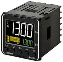


E5CD-QX2D6M-000
Temperature Controller, 1/16 DIN, ON/OFF Control, PID Control, -200 °C to 2300 °C, 20.4 V to 26.4 V
- Manufacturer: OMRON INDUSTRIAL AUTOMATION
- Product type: Temperature Controllers
- SVHC: To Be Advised
- Product Range: E5CD
- Thermocouple Type: B, C, E, J, K, L, N, R, S, T, U, W, PLII
- Output Voltage Max: 250VAC
- Output Voltage Min: -
- Temperature Accuracy ±: 1°C
- Operating Temperature Max: 55°C
- Operating Temperature Min: -10°C
| Delivery and price | |
|---|---|
| Units per pack | 1 |
| Price | 296.57 € |
| Current stock | 10+ |
| Lead time | 30 days |
**New Product** ## **Digital Temperature Controller E5CD/E5ED** **Next Generation Digital Temperature Controllers with Expanded Adaptive Control Functionality** **E5CD (48 × 48 mm) and E5ED (48 × 96 mm) Push-In Plus technology models reduce wiring work E5CD-B (48 × 48 mm) and E5ED-B (48 × 96 mm)** Optimize control by detecting status changes. Easily satisfy both productivity and quality. Ideal for package sealing and water-cooled extrusion applications. 48 × 48 mm 48 × 96 mm **E5CD/E5CD-B E5ED/E5ED-B** Accurately Measure Seal Temperatures Temperature Sensors for Packaging Machines **==> picture [124 x 47] intentionally omitted <==** **----- Start of picture text -----**<br> Temperature Sensors<br>E52<br>Ferrule terminal type added<br>**----- End of picture text -----**<br> **1** ## **Digital Temperature Controller - E5CD/E5CD B (48 × 48 mm)** ## **Optimize Control by Detecting Status Changes.** ## **Easily Satisfy Both Productivity and Quality.** ## **Models with Push-In Plus** ## **Technology Available in the Lineup.** - Automatic optimization of control for changes in systems (Adaptive Control). - Functions specialized for packaging machines (Temperature Sensors for Packaging Machines and Automatic Filter Adjustment). - Function specialized for water-cooled extruders (Watercooling Output Adjustment). - Indication data (Power ON Time, Ambient Temperature, and Output ON/OFF Count). **==> picture [200 x 22] intentionally omitted <==** **----- Start of picture text -----**<br> 48 × 48 mm 48 × 48 mm<br>Screw Terminal Blocks Push-In Plus Terminal Blocks<br>E5CD E5CD-B<br>**----- End of picture text -----**<br> For the most recent information on models that have been certified for safety standards, refer to your OMRON website. **Refer to** _**Safety Precautions**_ **on 43.** - Basic performance is same as the E5C standard models. - Draw-out structure for easy maintenance. (Screw terminal blocks only) ## **Main I/O Functions** **==> picture [495 x 241] intentionally omitted <==** **----- Start of picture text -----**<br> E5CD/E5CD-B<br>Sensor Input<br>Universal input<br>• Thermocouple Dual displays: PV/SV 4-digit displays Bar displays<br>• Pt<br>• Analog current/voltage<br>Control Output 1<br>•Indication Accuracy Thermocouple input • Relay output<br>±0.3%PV • Voltage output<br>• Pt input: ±0.2% of PV (for driving SSR)<br>• Analog input: ±0.2% of • Linear current output<br>FS<br>Auxiliary Outputs <E5CD><br>Sampling Period<br>• 50 ms • 2 independent outputs<br>Auxiliary Outputs <E5CD-B><br>• 2 outputs<br>Event Inputs • Adaptive Control<br>• None —— ey |<br>• 2 • Automatic Filter Adjustment Transfer Output<br>• Water-cooling Output Adjustment • None<br>• Indication Data<br>Serial Communications • 1<br>Power ON Time<br>• None<br>• RS-485 Ambient Temperature<br>Output ON/OFF Count<br>**----- End of picture text -----**<br> **This datasheet is provided as a guideline for selecting products.** **Be sure to refer to the following manuals for application precautions and other information required for operation before attempting to use the product.** **E5** @ **D Digital Temperature Controllers User’s Manual (Cat. No. H224)** **E5** @ **D Digital Temperature Controllers Communications Manual (Cat. No. H225)** **2** **E5CD/E5CD-B** **Model Number Legend and Standard Models** ## **Model Number Legend** ## **Models with Screw Terminal Blocks** > **E5CD-** −−−−−− @@ A **2** B @ C **6** D **M -** E −−− @@@ F **(Example: E5CD-RX2A6M-000)** |**Model**|A|B|C|D|E|F|**Meaning**|**Meaning**|**Meaning**|**Meaning**| |---|---|---|---|---|---|---|---|---|---|---| ||**Control outputs**<br>**1 and 2**|**No. of**<br>**auxiliary**<br>**outputs**|**Power**<br>**supply**<br>**voltage**|**Terminal**<br>**type**|**Input**<br>**type**|**Options**||||| |**E5CD**|||||||**48**×**48 mm**|||| ||||||||**Control output 1**||**Control output 2**|| ||**RX**||||||Relay output||None|| ||**QX**||||||Voltage output<br>(for drivingSSR)||None|| ||**CX**||||||Linear current output||None|| |||**2**|||||2 independent outputs|||| ||||**A**||||100 to 240 VAC|||| ||||**D**||||24 VAC/DC|||| |||||**6**|||Screw terminal blocks (with E53-COV23 Terminal<br>Cover), draw-out structure|||| ||||||**M**||Universal input|||| ||||||***1**<br>***1**<br>***2**<br>***2**||**HB alarm and**<br>**HS alarm**|**Communications**|**Event**<br>**inputs**|**Transfer**<br>**Output**| |||||||000|---|---|---|---| |||||||001|1|---|2|---| |||||||002|1|RS-485|---|---| |||||||004|---|RS-485|2|---| |||||||006|---|---|2|Provided.| - *1. This option can be selected when the control output is RX or QX. - *2. This option can be selected when the control output is CX. ## **Heating and Cooling Control** ## **Using Heating and Cooling Control** A Control Output Assignment An auxiliary output is used as the cooling control output. B Control If PID control is used, you can set PID control separately for heating and cooling. This allows you to handle control systems with different heating and cooling response characteristics. ## **List of Models** |**Model**<br>**E5CD-RX2A6M-000**<br>**E5CD-RX2D6M-000**<br>**E5CD-RX2A6M-001**<br>**E5CD-RX2D6M-001**<br>**E5CD-RX2A6M-002**<br>**E5CD-RX2D6M-002**<br>**E5CD-QX2A6M-000**<br>**E5CD-QX2D6M-000**<br>**E5CD-QX2A6M-001**<br>**E5CD-QX2D6M-001**<br>**E5CD-QX2A6M-002**<br>**E5CD-QX2D6M-002**|**Model**| |---|---| ||**E5CD-CX2A6M-000**| ||**E5CD-CX2D6M-000**| ||**E5CD-CX2A6M-004**| ||**E5CD-CX2D6M-004**| ||**E5CD-CX2A6M-006**| ||**E5CD-CX2D6M-006**| ||| **3** **E5CD/E5CD-B** ## **Model Number Legend** ## **Models with Push-In Plus Terminal Blocks** > **E5CD-** −−−−−− @@ A B **2** @ C **B** D **M -** E −−− @@@ F **(Example: E5CD-RX2ABM-000)** |**Model**|A|B|C|D|E|F|**Meaning**|**Meaning**|**Meaning**|**Meaning**| |---|---|---|---|---|---|---|---|---|---|---| ||**Control outputs**<br>**1 and 2**|**No. of**<br>**auxiliary**<br>**outputs**|**Power**<br>**supply**<br>**voltage**|**Terminal**<br>**type**|**Input**<br>**type**|**Options**||||| |**E5CD**|||||||**48**×**48 mm**|||| ||||||||**Control output 1**||**Control output 2**|| ||**RX**||||||Relayoutput||None|| ||**QX**||||||Voltage output<br>(for drivingSSR)||None|| ||**CX**||||||Linear current output||None|| |||**2**|||||2 independent outputs|||| ||||**A**||||100 to 240 VAC|||| ||||**D**||||24 VAC/DC|||| |||||**B**|||Push-In Plus terminal block|||| ||||||**M**||Universal input|||| ||||||***1**<br>***1**<br>***2**<br>***2**||**HB alarm and**<br>**HS alarm**|**Communications**|**Event**<br>**inputs**|**Transfer**<br>**Output**| |||||||000|---|---|---|---| |||||||001|1|---|2|---| |||||||002|1|RS-485|---|---| |||||||004|---|RS-485|2|---| |||||||006|---|---|2|Provided.| *1. This option can be selected when the control output is RX or QX. - *2. This option can be selected when the control output is CX. ## **Heating and Cooling Control** ## **Using Heating and Cooling Control** A Control Output Assignment An auxiliary output is used as the cooling control output. B Control If PID control is used, you can set PID control separately for heating and cooling. This allows you to handle control systems with different heating and cooling response characteristics. ## **List of Models** |**Model**<br>**E5CD-RX2ABM-000**<br>**E5CD-RX2DBM-000**<br>**E5CD-RX2ABM-001**<br>**E5CD-RX2DBM-001**<br>**E5CD-RX2ABM-002**<br>**E5CD-RX2DBM-002**<br>**E5CD-QX2ABM-000**<br>**E5CD-QX2DBM-000**<br>**E5CD-QX2ABM-001**<br>**E5CD-QX2DBM-001**<br>**E5CD-QX2ABM-002**<br>**E5CD-QX2DBM-002**|**Model**| |---|---| ||**E5CD-CX2ABM-000**| ||**E5CD-CX2DBM-000**| ||**E5CD-CX2ABM-004**| ||**E5CD-CX2DBM-004**| ||**E5CD-CX2ABM-006**| ||**E5CD-CX2DBM-006**| ||| **4** **E5CD/E5CD-B** ## **Optional Products (Order Separately) USB-Serial Conversion Cable** **Model E58-CIFQ2** ## **Terminal Covers** (Cannot be used on a Push-In Plus terminal block type) **Model E53-COV17 E53-COV23 (3pcs)** * **Note:** The E53-COV10 cannot be used. Refer to page 14 for the mounted dimensions. * E53-COV23 are provided with the Digital Temperature Controller. ## **Waterproof Packing** ## **Model Y92S-P8** **Note:** This Waterproof Packing is provided with the Digital Temperature Controller. ## **Front Covers** |**Type**|**Model**| |---|---| |Hard Front Cover|**Y92A-48H**| |Soft Front Cover|**Y92A-48D**| ## **Draw-out Jig** (Cannot be used on a Push-In Plus terminal block type) ## **Model Y92F-58** ## **CX-Thermo Support Software** ## **Model** ## **EST2-2C-MV4** **Note:** CX-Thermo version 4.66 or higher is required for the E5CD. CX-Thermo version 4.67 or higher is required for the E5CD-B. For the system requirements for the CX-Thermo, refer to information on the EST2-2C-MV4 on the OMRON website (www.ia.omron.com). ## **Current Transformers (CTs)** |**Hole diameter**|**Model**| |---|---| |5.8 mm|**E54-CT1**| |5.8 mm|**E54-CT1L***| |12.0 mm|**E54-CT3**| |12.0 mm|**E54-CT3L***| * Lead wires are included with these CTs. If UL certification is required, use these CTs. ## **Adapter** ## **Model** ## **Y92F-45** **Note:** Use this Adapter when the panel has already been prepared for an E5B @ Controller. ## **Waterproof Cover** **Model Y92A-48N** ## **Mounting Adapter** **Model Y92F-49** **Note:** This Mounting Adapter is provided with the Digital Temperature Controller. ## **DIN Track Mounting Adapter** (Cannot be used on a Push-In Plus terminal block type) **Model Y92F-52** **5** **E5CD/E5CD-B Specifications** ## **Ratings** |**E5CD/E5CD-B**<br>**Specifications**<br>**Ratings**|**E5CD/E5CD-B**<br>**Specifications**<br>**Ratings**|| |---|---|---| |**Power supply voltage**||A in model number: 100 to 240 VAC, 50/60 Hz<br>D in model number: 24 VAC, 50/60 Hz; 24 VDC| |**Operating voltage range**||85% to 110% of rated supply voltage| |**Power consumption**||Models with option selection of 000:5.2 VA max. at 100 to 240 VAC, and 3.1 VA max. at 24 VAC or 1.6 W max.<br>at 24 VDC<br>All other models: 6.5 VA max. at 100 to 240 VAC, and 4.1 VA max. at 24 VAC or 2.3 W max. at 24 VDC| |**Sensor input**||Temperature input<br>Thermocouple: K, J, T, E, L, U, N, R, S, B, C/W, or PL II<br>Platinum resistance thermometer: Pt100 or JPt100<br>Infrared temperature sensor (ES1B): 10 to 70°C, 60 to 120°C, 115 to 165°C, or 140 to 260°C<br>Analog input<br>Current input: 4 to 20 mA or 0 to 20 mA<br>Voltage input: 1 to 5 V, 0 to 5 V, or 0 to 10 V| |**Input impedance**||Current input: 150Ωmax., Voltage input: 1 MΩmin.<br>(Use a 1:1 connection when connectingthe ES2-HB/THB.)| |**Control method**||ON/OFF control or 2-PID control (with auto-tuning)| |**Control**<br>**output**|**Relay output**|SPST-NO, 250 VAC, 3 A (resistive load), electrical life: 100,000 operations, minimum applicable load: 5 V, 10<br>mA (reference value)| ||**Voltage output**<br>**(for driving SSR)**|Output voltage: 12 VDC±20% (PNP), max. load current: 21 mA, with short-circuit protection circuit| ||**Linear current**<br>**output**|4 to 20 or 0 to 20 mA DC, Load: 500Ωmax., Resolution: Approx. 10,000| |**Auxiliary**<br>**output**|**Number of**<br>**outputs**|2| ||**Output**<br>**specifications**|SPST-NO relay outputs: 250 VAC, E5CD: 3 A (resistive load), E5CD-B: 2 A (resistive load)<br>Electrical life: 100,000 operations, Minimum applicable load: 10 mA at 5 V (reference values)| |**Event**<br>**input**|**Number of inputs**|2| ||**External contact**<br>**input**<br>**specifications**|Contact input: ON: 1 kΩmax., OFF: 100 kΩmin.| |||Non-contact input: ON: Residual voltage: 1.5 V max., OFF: Leakage current: 0.1 mA max.| |||Current flow: Approx. 7 mA per contact| |**Transfer**<br>**Output**|**Number of**<br>**outputs**|1 (depends on model): Transfer output type| ||**Output**<br>**specifications**|Current output: 4 to 20 mA DC, Load: 500Ω, Resolution: Approx. 10,000<br>Linear voltage output: 1 to 5 V DC, Load: 1 kΩmin., Resolution: Approx. 10,000| |**Setting method**||Digital settingusingfront panel keys| |**Indication method**||11-segment digital display, individual indicators, and bar display<br>Character height: PV: 14.9 mm, SV: 7.1 mm| |**Multi SP***||Up to eight set points (SP0 to SP7) can be saved and selected using the event inputs, key operations, or serial<br>communications.| |**Bank switching**||None| |**Other functions**||Adaptive control, automatic filter adjustment, water-cooling output adjustment, indication data (power ON time<br>monitor, ambient temperature monitor, and control output ON/OFF count monitors), parameter masking,<br>operation after power ON, manual output, heating/cooling control, loop burnout alarm, SP ramp, other alarm<br>functions, heater burnout (HB) alarm (including SSR failure (HS) alarm), 40% AT, 100% AT, MV limiter, input<br>digital filter, robust tuning, PV input shift, run/stop, protection functions, extraction of square root, MV change<br>rate limit, logic operations, temperature status display, simple programming, moving average of input value, and<br>displaybrightness setting| |**Ambient operating**<br>**temperature**||−10 to 55°C (with no condensation or icing),<br>For 3-year warranty:−10 to 50°C with standard mounting(with no condensation or icing)| |**Ambient operating humidity**||25% to 85%| |**Storage temperature**||−25 to 65°C (with no condensation or icing)| |**Altitude**||2,000 m max.| |**Recommended fuse**||T2A, 250 VAC, time-lag, low-breakingcapacity| |**Installation environment**||Overvoltage categoryII, Pollution Degree 2 (EN/IEC/UL 61010-1)| * There can be up to four set points if event inputs are used to select them. **6** **E5CD/E5CD-B** ## **Input Ranges** ## **Thermocouple/Platinum Resistance Thermometer (Universal inputs)** |**Sensor**<br>**type**|**Platinum resistance**<br>**thermometer**|**Platinum resistance**<br>**thermometer**|**Platinum resistance**<br>**thermometer**|**Platinum resistance**<br>**thermometer**|**Platinum resistance**<br>**thermometer**|**Platinum resistance**<br>**thermometer**|**Platinum resistance**<br>**thermometer**|**Thermocouple**|**Thermocouple**|**Thermocouple**|**Thermocouple**|**Thermocouple**|**Thermocouple**|**Thermocouple**|**Thermocouple**|**Thermocouple**|**Thermocouple**|**Thermocouple**|**Thermocouple**|**Thermocouple**|**Thermocouple**|**Thermocouple**|**Thermocouple**|**Thermocouple**|**Thermocouple**|**Infrared temperature**<br>**sensor**|**Infrared temperature**<br>**sensor**|**Infrared temperature**<br>**sensor**|**Infrared temperature**<br>**sensor**| |---|---|---|---|---|---|---|---|---|---|---|---|---|---|---|---|---|---|---|---|---|---|---|---|---|---|---|---|---|---| |**Sensor**<br>**specification**|**Pt100**|||||**JPt100**||**K**||||**J**||**T**||**E**|**L**|**U**||**N**|**R**|**S**|**B**|**C/W**|**PLII**|10 to<br>70°C|60 to<br>120°C|115 to<br>165°C|140 to<br>260°C| |2300<br>1800<br>1700<br>1600<br>1500<br>1400<br>1300<br>1200<br>1100<br>1000<br>900<br>800<br>700<br>600<br>500<br>400<br>300<br>200<br>100<br>0<br>−100<br>−200<br>**Temperature range (°C)**||||||||||||||||||||||||2300|||||| ||||||||||||||||||||||||1800||||||| ||||||||||||||||||||||1700|1700|||||||| ||||||||||||||||||||||||||||||| ||||||||||||||||||||||||||||||| ||||||||||||||||||||||||||||||| |||||||||1300||||||||||||1300|||||1300||||| ||||||||||||||||||||||||||||||| ||||||||||||||||||||||||||||||| ||||||||||||||||||||||||||||||| ||850|||||||||||850|||||850||||||||||||| ||||||||||||||||||||||||||||||| ||||||||||||||||||||||||||||||| ||||||||||||||||||||||||||||||| |||||||||||||||||600|||||||||||||| |||||500.0||500.0|||||500.0||||||||||||||||||| ||||||||||||||400.0|400|400.0|||400|400.0||||||||||| ||||||||||||||||||||||||||||||260| ||||||||||||||||||||||||||||120|165|| ||||||100.0||100.0|||||||||||||||||||90|||| ||||||||||||||||||||||||||||||| ||||||0.0||0.0||||||||||||||0|0|0|0|0|0|0|0|0| ||||||||||||−20.0|−100|−20.0||||−100||||||||||||| ||−200|||−199.9||−199.9||−200||||||−200|−199.9|−200||−200|−199.9|−200|||||||||| |**Set value**|0|||1|2|3|4|5|||6|7|8|9|10|11|12|13|14|15|16|17|18|19|20|21|22|23|24| |Shaded settings are the default settings.|||||||||||||||||||||||||||||| The applicable standards for the input types are as follows: K, J, T, E, N, R, S, B: JIS C 1602-2015, IEC 60584-1 JPt100: JIS C 1604-1989, JIS C 1606-1989 L: Fe-CuNi, DIN 43710-1985 Pt100: JIS C 1604-1997, IEC 60751 U: Cu-CuNi, DIN 43710-1985 PL II: According to Platinel II electromotive force charts from BASF (previously Engelhard) C/W: W5Re/W26Re, JIS C1602-2015, ASTM E988-1990 ## **Analog input** |**Input type**|**Current**|**Current**|**Voltage**|**Voltage**|**Voltage**| |---|---|---|---|---|---| |**Input**<br>**specification**|4 to 20 mA|0 to 20 mA|1 to 5 V|0 to 5 V|0 to 10 V| |**Setting range**|Usable in the following ranges by scaling:<br>−1999 to 9999,−199.9 to 999.9,<br>−19.99 to 99.99 or−1.999 to 9.999||||| |**Set value**|25|26|27|28|29| **7** **E5CD/E5CD-B** ## **Alarm Types** Each alarm can be independently set to one of the following 17 alarm types. The default is 2: Upper limit. (see note.) Auxiliary outputs are allocated for alarms. ON delays and OFF delays (0 to 999 s) can also be specified. **Note:** In the default settings for models with HB or HS alarms, alarm 1 is set to a heater alarm (HA) and the Alarm Type 1 parameter is not displayed. To use alarm 1, set the output assignment to alarm 1. |**Set**<br>**value**|**Alarm type**|**Alarm output operation**|**Alarm output operation**|**Alarm output operation**|**Alarm output operation**|**Alarm output operation**|**Alarm output operation**|**Alarm output operation**|**Alarm output operation**|**Alarm output operation**|**Alarm output operation**|**Description of function**| |---|---|---|---|---|---|---|---|---|---|---|---|---| |||**When alarm value X**<br>**is positive**||||||**When alarm value X**<br>**is negative**||||| |0|Alarm function OFF|||||Output OFF||||||No alarm| |1|Upper- and lower-limit*1|ON<br>OFF||L||PV<br>P<br>H||*2||||Set the upward deviation in the set point for the alarm upper<br>limit (H) and the lower deviation in the set point for the alarm<br>lower limit (L). The alarm is ON when the PV is outside this<br>deviation range.| |||||||||||||| |||||S||||||||| |2<br>(default)|Upper-limit|ON<br>OFF||||P<br>X<br>PV||ON<br>OFF|SP<br>X<br>PV|||Set the upward deviation in the set point by setting the alarm<br>value (X). The alarm is ON when the PV is higher than the<br>SP bythe deviation or more.| |||||S||||||||| |3|Lower-limit|ON<br>OFF||X||P<br>PV||ON<br>OFF|SP<br>X<br>PV|||Set the downward deviation in the set point by setting the<br>alarm value (X). The alarm is ON when the PV is lower than<br>the SP by the deviation or more.| |||||||||||||| |||||S||||||||| |4|Upper- and lower-limit<br>range*1|ON<br>OFF||L||P<br>H<br>PV||*3||||Set the upward deviation in the set point for the alarm upper<br>limit (H) and the lower deviation in the set point for the alarm<br>lower limit (L). The alarm is ON when the PV is inside this<br>deviation range.| |||||||||||||| |||||S||||||||| |5|Upper- and lower-limit with<br>standby sequence*1|ON<br>OFF<br>*5|||L|H||*4||||A standby sequence is added to the upper- and lower-limit<br>alarm (1).*6| |||||||||||||| |||||S||||||||| |6|Upper-limit with standby<br>sequence|ON<br>OFF||||X||ON<br>OFF||X||A standby sequence is added to the upper-limit alarm (2).*6| |||||||||||||| |||||S||||||||| |7|Lower-limit with standby<br>sequence|ON<br>OFF|||X|P<br>PV||ON<br>OFF|||X|A standby sequence is added to the lower-limit alarm (3).*6| |||||||||||||| |||||S||||||||| |8|Absolute-value upper-<br>limit|ON<br>OFF||||X||ON<br>OFF||X||The alarm will turn ON if the process value is larger than the<br>alarm value (X) regardless of the set point.| |||||||||||||| |||||0||||||||| |9|Absolute-value lower-limit|ON<br>OFF||||X||ON<br>OFF||X||The alarm will turn ON if the process value is smaller than the<br>alarm value (X) regardless of the set point.| |||||||||||||| |||||0||||||||| |10|Absolute-value upper-<br>limit with standby<br>sequence|ON<br>OFF||||X|||0<br>X<br>PV|||A standby sequence is added to the absolute-value upper-<br>limit alarm (8).*6| ||||||||PV|ON<br>OFF||||| |||||0||||||||| |11|Absolute-value lower-limit<br>with standby sequence|ON<br>OFF||||X||ON<br>OFF||X||A standby sequence is added to the absolute-value lower-<br>limit alarm (9).*6| |||||||||||||| |||||0||||||||| |12|LBA (alarm 1 type only)|||||-||||||*7| |13|PV change rate alarm|||||-||||||*8| |14|SP absolute-value<br>upper-limit alarm|ON<br>OFF||||X||||X||This alarm type turns ON the alarm when the set point (SP)<br>is higher than the alarm value (X).| ||||||||SP|ON<br>OFF||||| |||||0||||||||| |15|SP absolute-value<br>lower-limit alarm|ON<br>OFF||||X||ON<br>OFF||X||This alarm type turns ON the alarm when the set point (SP)<br>is lower than the alarm value (X).| |||||||||||||| |||||0||||||||| |16|MV absolute-value<br>upper-limit alarm*9|Standard Control<br>0<br>X<br>ON<br>OFF<br>MV||||||Standard Control<br>0<br>X<br>ON<br>OFF<br>MV||||This alarm type turns ON the alarm when the manipulated<br>variable (MV) is higher than the alarm value (X).| |||Heating/Cooling<br>Control (Heating MV)<br>0<br>X<br>ON<br>OFF<br>MV||||||Heating/Cooling<br>Control (Heating MV)<br>Always ON||||| |17|MV absolute-value<br>lower-limit alarm*9|Standard Control<br>0<br>X<br>ON<br>OFF<br>MV||||||Standard Control<br>0<br>X<br>ON<br>OFF<br>MV||||This alarm type turns ON the alarm when the manipulated<br>variable (MV) is lower than the alarm value (X).| |||Heating/Cooling<br>Control (Cooling MV) <br>0<br>X<br>ON<br>OFF<br>MV||||||Heating/Cooling<br>Control (Cooling MV)<br>Always ON||||| **8** **E5CD/E5CD-B** *1. With set values 1, 4 and 5, the upper and lower limit values can be set independently for each alarm type, and are expressed as “L” and “H.” - *2. Set value: 1, Upper- and lower-limit alarm |Case 1|||Case 2|Case 3|Case 3|(Always ON)|(Always ON)|(Always ON)|(Always ON)|H<0, L<0| |---|---|---|---|---|---|---|---|---|---|---| |L<br>H|SP||L<br>H<br>SP|H|||SP||L|| |H<0, L>0<br>|H| < |L||||H>0, L<0<br>|H| > |L||H||L<br>SP||||H<0, L>0<br>|H|≥|L|| |||||||||||H>0, L<0| ||||||||SP|H|L||H|≤|L|| |Set value: 4,|||Upper- and lower-limit range|||||||| |Case 1|||Case 2|Case 3|(Always|||OFF)||| |L<br>H|SP||L<br>H<br>SP|H|||SP|L||H<0, L<0| |H<0, L>0|||H>0, L<0|||||||H<0, L>0| ||H| < |L|||||H| > |L||H||L|SP||||H|≥|L|| |||||||||||H>0, L<0| ||||||||H<br>SP||L||H|≤|L|| *3. Set value: 4, Upper- and lower-limit range - *4. Set value: 5, Upper- and lower-limit with standby sequence - For Upper- and Lower-Limit Alarm Described Above *2 - Case 1 and 2 Always OFF when the upper-limit and lower-limit hysteresis overlaps. - Case 3: Always OFF - *5. Set value: 5, Upper- and lower-limit with standby sequence Always OFF when the upper-limit and lower-limit hysteresis overlaps. - *6. Refer to the _E5_ @ _D Digital Temperature Controllers User's Manual_ (Cat. No. H224) for information on the operation of the standby sequence. - *7. Refer to the _E5_ @ _D Digital Temperature Controllers User's Manual_ (Cat. No.H224) for information on the loop burnout alarm (LBA). - *8. Refer to the _E5_ @ _D Digital Temperature Controllers User's Manual_ (Cat. No. H224) for information on the PV change rate alarm. - *9. When heating/cooling control is performed, the MV absolute upper limit alarm functions only for the heating operation and the MV absolute lower limit alarm functions only for the cooling operation. **9** **E5CD/E5CD-B** ## **Characteristics** |**Characteristics**|**Characteristics**|| |---|---|---| |**Indication accuracy**<br>**(at the ambient temperature of 23°C)**||Thermocouple: (±0.3% of indication value or±1°C, whichever is greater)±1 digit max.*1<br>Platinum resistance thermometer: (±0.2% of indication value or±0.8°C, whichever is greater)±1 digit max.<br>Analog input:±0.2% FS±1 digit max.<br>CT input:±5% FS±1 digit max.| |**Transfer output accuracy**||±0.3% FS max.| |**Influence of temperature*2**||Thermocouple input (R, S, B, C/W, PL II): (±1% of indication value or±10°C, whichever is greater)±1 digit max.<br>Other thermocouple input: (±1% of indication value or±4°C, whichever is greater)±1 digit max.*3<br>Platinum resistance thermometer: (±1% of indication value or±2°C, whichever is greater)±1 digit max.<br>Analog input:±1%FS±1 digit max.<br>CT input:±5% FS±1 digit max.| |**Influence of voltage*2**||| |**Influence of EMS.**<br>**(at EN 61326-1)**||| |**Input sampling period**||50 ms| |**Hysteresis**||Temperature input: 0.1 to 999.9°C or °F (in units of 0.1°C or °F)<br>Analog input: 0.01% to 99.99% FS (in units of 0.01% FS)| |**Proportional band (P)**||Temperature input: 0.1 to 999.9°C or °F (in units of 0.1°C or °F)<br>Analog input: 0.1% to 999.9% FS (in units of 0.1% FS)| |**Integral time (I)**||0 to 9999 s (in units of 1 s), 0.0 to 999.9 s (in units of 0.1 s)*4| |**Derivative time (D)**||0 to 9999 s (in units of 1 s), 0.0 to 999.9 s (in units of 0.1 s)*4| |**Proportional band (P) for cooling**||Temperature input: 0.1 to 999.9°C or °F (in units of 0.1°C or °F)<br>Analog input: 0.1% to 999.9% FS (in units of 0.1% FS)| |**Integral time (I) for cooling**||0 to 9999 s (in units of 1 s), 0.0 to 999.9 s (in units of 0.1 s)*4| |**Derivative time (D) for cooling**||0 to 9999 s (in units of 1 s), 0.0 to 999.9 s (in units of 0.1 s)*4| |**For**<br>**adaptive**<br>**control**|**SP response proportional band**|Temperature input: 0.1 to 999.9°C or °F (in units of 0.1°C or °F)| ||**SP response integral time**|0 to 9999 s (in units of 1 s), 0.0 to 999.9 s (in units of 0.1 s)*4| ||**SP response derivative time**|0 to 9999 s (in units of 1 s), 0.0 to 999.9 s (in units of 0.1 s)*4| ||**Disturbance proportional band**|Temperature input: 0.1 to 999.9°C or °F (in units of 0.1°C or °F)| ||**Disturbance integral time**|0 to 9999 s (in units of 1 s), 0.0 to 999.9 s (in units of 0.1 s)*4| ||**Disturbance derivative time**|0 to 9999 s (in units of 1 s), 0.0 to 999.9 s (in units of 0.1 s)*4| |**Control period**||0.1, 0.2, 0.5, 1 to 99 s (in units of 1 s)| |**Manual reset value**||0.0 to 100.0% (in units of 0.1%)| |**Alarm setting range**||−1999 to 9999 (decimal point position depends on input type)| |**Influence of signal source resistance**||Thermocouple: 0.1°C/Ωmax. (100Ωmax.)<br>Platinum resistance thermometer: 0.1°C/Ωmax. (10Ωmax.)| |**Insulation resistance**||20 MΩmin. (at 500 VDC)| |**Dielectric strength**||3,000 VAC, 50/60 Hz for 1 min between terminals of different charge| |**Vibration**|**Malfunction**|10 to 55 Hz, 20 m/s2for 10 min each in X, Y, and Z directions| ||**Resistance**|10 to 55 Hz, 20 m/s2for 2 hrs each in X, Y, and Z directions| |**Shock**|**Malfunction**|100 m/s2, 3 times each in X, Y, and Z directions| ||**Resistance**|300 m/s2, 3 times each in X, Y, and Z directions| |**Weight**||Controller: Approx. 120 g, Mounting Adapter: Approx. 10 g| |**Degree of protection**||Front panel: IP66, Rear case: IP20, Terminals: IP00| |**Memory protection**||Non-volatile memory (number of writes: 1,000,000 times)| |**Setup Tool**||E5CD: CX-Thermo version 4.66 or higher<br>E5CD-B: CX-Thermo version 4.67 or higher| |**Setup Tool port**||E5CD/E5CD-B top panel: An E58-CIFQ2 USB-Serial Conversion Cable is used to connect to a USB port on<br>the computer.*5| |**Standards**|**Approved standards**|cULus: UL 61010-1/CSA C22.2 No.61010-1,<br>Korean wireless regulations (Radio law: KC Mark)| ||**Conformed standards**|EN 61010-1 (IEC 61010-1) and RCM standards| |**EMC**||EMI:<br>EN 61326-1*6<br>Radiated Interference Electromagnetic Field Strength:<br>EN 55011 Group 1, class A<br>Noise Terminal Voltage:<br>EN 55011 Group 1, class A<br>EMS:<br>EN 61326-1*6<br>ESD Immunity:<br>EN 61000-4-2<br>Electromagnetic Field Immunity:<br>EN 61000-4-3<br>Burst Noise Immunity:<br>EN 61000-4-4<br>Conducted Disturbance Immunity:<br>EN 61000-4-6<br>Surge Immunity:<br>EN 61000-4-5<br>Voltage Dip/Interrupting Immunity:<br>EN 61000-4-11| *1. The indication accuracy of K thermocouples in the − 200 to 1,300°C range, T and N thermocouples at a temperature of − 100°C max., and U and L thermocouples at any temperatures is ± 2°C ± 1 digit max. The indication accuracy of the B thermocouple at a temperature of 400°C max. is not specified. The indication accuracy of B thermocouples at a temperature of 400 to 800°C is ± 3°C max. The indication accuracy of the R and S thermocouples at a temperature of 200°C max. is ± 3°C ± 1 digit max. The indication accuracy of C/W thermocouples is ( ± 0.3% of PV or ± 3°C, whichever is greater) ± 1 digit max. The indication accuracy of PL II thermocouples is ( ± 0.3% of PV or ± 2°C, whichever is greater) ± 1 digit max. *2. Ambient temperature: − 10°C to 23°C to 55°C, Voltage range: − 15% to 10% of rated voltage *3. K thermocouple at − 100°C max.: ± 10°C max. *4. The unit is determined by the setting of the Integral/Derivative Time Unit parameter. *5. External communications (RS-485) and USB-serial conversion cable communications can be used at the same time. *6. Industrial electromagnetic environment (EN/IEC 61326-1 Table 2) **10** **E5CD/E5CD-B** ## **USB-Serial Conversion Cable** ## **Communications Functions** |**USB-Serial**|**Conversion Cable**| |---|---| |**Applicable OS**|Windows XP/Vista/7/8/10*1| |**Applicable**<br>**software**|CX-Thermo version 4.66 or higher<br>(E5CD-B: version 4.67 or higher)| |**Applicable**<br>**models**|E5@C-T Series, E5@C Series, E5CB Series, and<br>E5@D Series| |**USB interface**<br>**standard**|Conforms to USB Specification 2.0.| |**DTE speed**|38,400 bps| |**Connector**<br>**specifications**|Computer: USB (type A plug)<br>Digital Temperature Controller:<br>Special serial connector| |**Power supply**|Bus power (Supplied from USB host controller.)*2| |**Power supply**<br>**voltage**|5 VDC| |**Current**<br>**consumption**|450 mA max.| |**Output voltage**|4.7±0.2 VDC<br>(Supplied from USB-Serial Conversion Cable to the<br>Digital Temperature Controller.)| |**Output current**|250 mA max.<br>(Supplied from USB-Serial Conversion Cable to the<br>Digital Temperature Controller.)| |**Ambient**<br>**operating**<br>**temperature**|0 to 55°C (with no condensation or icing)| |**Ambient operating**<br>**humidity**|10% to 80%| |**Storage**<br>**temperature**|−20 to 60°C (with no condensation or icing)| |**Storage**<br>**humidity**|10% to 80%| |**Altitude**|2,000 m max.| |**Weight**|Approx. 120g| |**Programless**<br>**communications**|You can use the memory in the PLC to read and write<br>E5CD/E5CD-B parameters, start and stop operation,<br>etc. The E5CD/E5CD-B automatically performs<br>communications with PLCs. No communications<br>programming is required.<br>Number of connected Digital Temperature Controllers: 32<br>max. (Up to 16 for the FX3)<br>Applicable PLCs<br>OMRON PLCs<br>CS Series, CJ Series, CP<br>Series, NJ Series, or NX1P<br>Mitsubishi Electric PLCs<br>MELSEC Q Series, L Series,<br>FX3 Series, or iQ-R Series<br>KEYENCE PLCs<br>KEYENCE KV Series| |---|---| |**Copying***|When Digital Temperature Controllers are connected,<br>the parameters can be copied from the Digital<br>Temperature Controller that is set as the master to the<br>Digital Temperature Controllers that are set as slaves.| MELSEC is a registered trademark of Mitsubishi Electric Corporation. KEYENCE is a registered trademark of Keyence Corporation. * Programless communications supports the copying function. ## **Current Transformer (Order Separately) Ratings** ||**E54-CT1**<br>**E54-CT3**|**E54-CT1L**<br>**E54-CT3L**| |---|---|---| |**Dielectric strength**|1,000 VAC for 1 min|1,500 VAC for 1 min| |**Vibration resistance**|50 Hz, 98 m/s2|| |**Weight**|E54-CT1: Approx. 11.5 g<br>E54-CT3: Approx. 50 g|E54-CT1L: Approx. 14 g<br>E54-CT3L: Approx. 57 g| |**Accessories**|E54-CT3 Only<br>Armatures (2)<br>Plugs (2)|None| ## **Heater Burnout Alarms and SSR Failure Alarms** |**Alarms**|| |---|---| |**CT input (for heater**<br>**current detection)**|Models with detection for single-phase<br>heaters: One input| |**Maximum heater current**|50 A AC| |**Input current**<br>**indication accuracy**|±5% FS±1 digit max.| |**Heater burnout alarm**<br>**setting range*1**|0.1 to 49.9 A (in units of 0.1 A)<br>Minimum detection ON time: 100 ms*3| |**SSR failure alarm**<br>**setting range *2**|0.1 to 49.9 A (in units of 0.1 A)<br>Minimum detection OFF time: 100 ms*4| Windows is a registered trademark of Microsoft Corporation in the United States and or other countries. - *1. CX-Thermo version 4.65 or higher runs on Windows 10. - *2. Use a high-power port for the USB port. **Note:** A driver must be installed on the computer. Refer to the _Instruction Manual_ included with the Cable for the installation procedure. ## **Communications Specifications** - *1. For heater burnout alarms, the heater current will be measured when the control output is ON, and the output will turn ON if the heater current is lower than the set value (i.e., heater burnout detection current value). |**Transmission**<br>**line connection**<br>**method**|RS-485: Multidrop|when the control output is ON, and the o<br>heater current is lower than the set value<br>detection current value).<br>*2.For SSR failure alarms, the heater current w|when the control output is ON, and the o<br>heater current is lower than the set value<br>detection current value).<br>*2.For SSR failure alarms, the heater current w| |---|---|---|---| |**Communications**|RS-485 (two-wire, half duplex)|control output is OFF, and the output|will tur| |**Synchronization**<br>**method**|Start-stop synchronization|is higher than the set value (i.e., SSR failure<br>*3.The value is 30 ms for a control period of|| |**Protocol**|CompoWay/F, or Modbus|*4.The value is 38 ms for a control period of|| |**Baud rate***<br>**Transmission**<br>**code**|9,600, 19,200, 38,400, 57,600, or 115,200 bps<br>ASCII|**Electrical Life Expectancy**<br>**Control Output Relay (Refe**|| |**Data bit length***<br>**Stop bit length***<br>**Error detection**<br>**Flow control**|7 or 8 bits<br>1 or 2 bits<br>Vertical parity (none, even, odd)<br>Block check character (BCC) with<br>CompoWay/F or CRC-16 Modbus<br>None|500<br>300<br>100<br>50<br>Life (× 104operations)|| |**Interface**|RS-485|30|| |**Retry function**|None||| |**Communications**<br>**buffer**<br>**Communications**<br>**response wait**<br>**time**|217 bytes<br>0 to 99 ms<br>Default: 20 ms|10<br>5<br>3<br>E5CD<br>250 VAC, 30 VDC<br>(resistive load)<br>~~cosφ = 1~~|| |*The baud rate, data bit length, stop bit length, and vertical parity can||1<br>0<br>1<br>2<br>3<br>4<br>5<br>6|| |be individually set|using the Communications Setting Level.|Switching current (A)|| - *2. For SSR failure alarms, the heater current will be measured when the control output is OFF, and the output will turn ON if the heater current is higher than the set value (i.e., SSR failure detection current value). - *3. The value is 30 ms for a control period of 0.1 s or 0.2 s. - *4. The value is 38 ms for a control period of 0.1 s or 0.2 s. ## **Electrical Life Expectancy Curve for Control Output Relay (Reference Values)** **11** **E5CD/E5CD-B External Connections** ## **E5CD (Screw Terminal Blocks)** **==> picture [458 x 417] intentionally omitted <==** **----- Start of picture text -----**<br> Control output 1 E5CD-@@@@ 2 @ 6 6 M - @@@ @@@<br>Relay output<br>250 VAC, 3 A (resistive load) (1) (2) (3) (4) (5) (6)<br>Voltage output ↑<br>(for driving SSR) Terminal type<br>12 VDC, 21 mA<br>Linear current output The E5CD is set for a K-type thermocouple (input type = 5) by<br>0 to 20 mA DC Auxiliary outputs 1, 2 default. An input error (s.err) will occur if the input type setting does s.err) will occur if the input type setting does ) will occur if the input type setting does<br>4 to 20 mA DC Relay outputs not agree with the temperature sensor. Check the input type.<br>Load: 500 Ω max<br>250 VAC, 3 A (resistive load)<br>(1) Control output 1<br>RX QX CX<br>Models with Models with 1 Models with 1<br>1 Relay Output Voltage Output Linear Current Output (2) Auxiliary Outputs<br>(for Driving SSR)<br>Auxiliary outputs 1, 2<br>1 OUT1 1 + OUT1 1 + OUT1 7<br>2 R 2 − Q 2 − C 8 Auxiliary output 2<br>9<br>Auxiliary output 1<br>1 13 7 10<br>2 14 8<br>(5) Sensor (Temperature/Analog) Input 3 15 9 (3) Input Power SupplyA D<br>4 16 10<br>TC Pt I V<br>4 A 4 + 4 4 5 17 11 100 to 240 VAC 24 VAC/DC<br>− B mA − 6 18 12 11 11<br>5 5 5 5<br>+ 6 B 6 − 6 V + 6 12 12<br>(no polarity)<br>(6) Options<br>001 002 004 006<br>Event Inputs 1 Communications Communications (RS-485), Event inputs 1and 2,<br>and 2, and CT1 (RS-485), CT1 Event Inputs 3 and 4 and transfer output<br>B(+) B(+)<br>(−) 13 RS-485 13 RS-485 13 (−) 13<br>EV1 14 A(−) 14 A(−) 14 EV1 14<br>EV2 15 15 15 EV2 15<br>CT1 1617 CT1 1617 (−) EV3 1617 1716 + I V+ Transfer Output<br>18 18 18 18 −<br>EV4<br>Use no-voltage inputs for the event inputs.<br>The polarity for non-contact inputs is given in parentheses.<br>**----- End of picture text -----**<br> **==> picture [195 x 67] intentionally omitted <==** **----- Start of picture text -----**<br> E5CD-@@@@ 2 @ 6 6 M - @@@ @@@<br>(1) (2) (3) (4) (5) (6)<br>↑<br>Terminal type<br>The E5CD is set for a K-type thermocouple (input type = 5) by<br>default. An input error (s.err) will occur if the input type setting does s.err) will occur if the input type setting does ) will occur if the input type setting does<br>not agree with the temperature sensor. Check the input type.<br>**----- End of picture text -----**<br> ## **Note: 1.** The application of the terminals depends on the model. **2.** Do not wire the terminals that are shown with a gray background. **3.** When complying with EMC standards, the cable that connects the sensor must be 30 m or less. If the cable length exceeds 30 m, compliance with EMC standards will not be possible. **4.** Connect M3 crimped terminals. **5.** Due to UL Listing requirements, use the E54-CT1L or E54-CT3L Current Transformer with the factory wiring (internal wiring). Use a UL category XOBA or XOBA7 current transformer that is UL Listed for field wiring (external wiring) and not the factory wiring (internal wiring). **12** **E5CD/E5CD-B** ## **E5CD-B (Push-In Plus Terminal Blocks)** **==> picture [501 x 389] intentionally omitted <==** **----- Start of picture text -----**<br> Control output 1 E5CD-@@ 2 @ B M - @@@<br>Relay output (1) (2) (3) (4) (5) (6)<br>250 VAC, 3 A (resistive load)<br>Voltage output ↑<br>(for driving SSR) Terminal type<br>12 VDC, 21 mA<br>Linear current output The E5CD-B is set for a K-type thermocouple (input type = 5) by<br>0 to 20 mA DC Auxiliary outputs 1, 2 default. An input error (s.err) will occur if the input type setting does<br>4 to 20 mA DC Relay outputs not agree with the temperature sensor. Check the input type.<br>Load: 500 Ω max 250 VAC, 2 A (resistive load)<br>(1) Control output 1<br>RX QX CX<br>Models with Models with 1 Models with 1 (2) Auxiliary Outputs<br>1 Relay Output Voltage Output Linear Current Output<br>(for Driving SSR) 1 17 9<br>1 OUT1 1 + OUT1 1 + OUT1 2 18 10 9<br>2 R 2 − Q 2 − C 3 19 11 Auxiliary output 2<br>10<br>4 20 12 *<br>(5) Sensor (Temperature/Analog) Input 5 21 13 11<br>Auxiliary output 1<br>TC Pt I V 6 22 14 12<br>6 A 6 + 6 6 7 23 15<br>− B mA −<br>7 B 7 − 7 V 7 8 24 16<br>+ 8 8 8 + 8 (3) Input Power Supply<br>100 to 240 VAC 24 VAC/DC<br>(6) Options<br>001 002 004 006 13 13<br>Event Inputs 1 Communications Communications (RS-485), Event inputs 1and 2, 14 * 14 *<br>and 2, and CT1 (RS-485), CT1 Event Inputs 3 and 4 and transfer output<br>(−) B(+) B(+) (−) 15 15<br>17 17 17 17 * *<br>(−) * * * (−) * 16 16<br>18 RS-485 18 RS-485 18 18<br>(no polarity)<br>19 19 19 19<br>EV1 A(−) * A(−) * EV1<br>20 20 20 20<br>EV2 EV2<br>21 21 (−) 21 21<br>CT1 22 CT1 22 (−) 22 * 22 +<br>23 23 23 23 + V Transfer Use non-voltage inputs for the event<br>EV3 I Output inputs.<br>24 24 24 24 − The polarity for a non-contact input<br>EV4 −<br>is indicated by “( ).”<br>**----- End of picture text -----**<br> - **Note: 1.** The application of the terminals depends on the model. **2.** Do not wire the terminals that are shown with a gray background. **3.** When complying with EMC standards, the cable that connects the sensor must be 30 m or less. If the cable length exceeds 30 m, compliance with EMC standards will not be possible. **4.** Refer to _E5_ @ _D-B (Push-In Plus terminal block types)_ on page 48 for wire specifications and wiring methods. **5.** Common terminals are indicated with Wiring Example: asterisks (*). 13 You can use the input power supply and communications common 14 terminals for crossover wiring. 15 Controllers given below if you use 16 crossover wiring for the input power supply. To another E5CD-B 100 to 240 VAC Controllers: 16 max. 24 VAC/VDC Controllers: 8 max. **6.** Due to UL Listing requirements, use the E54-CT1L or E54-CT3L Current Transformer with the factory wiring (internal wiring). Use a UL category XOBA or XOBA7 current transformer that is UL Listed for field wiring (external wiring) and not the factory wiring (internal wiring). ## **Isolation/Insulation Block Diagrams** ## **E5CD** **==> picture [214 x 122] intentionally omitted <==** **----- Start of picture text -----**<br> Sensor input and CT input<br>Communications and event inputs<br>Voltage output (for driving SSR),<br>Power linear current output, and transfer output<br>supply<br>Relay output<br>Auxiliary output 1<br>Auxiliary output 2<br>: Reinforced insulation<br>: Functional isolation<br>**----- End of picture text -----**<br> ## **E5CD-B** **==> picture [214 x 110] intentionally omitted <==** **----- Start of picture text -----**<br> Sensor input and CT input<br>Communications and event inputs<br>Voltage output (for driving SSR),<br>Power linear current output, and transfer output<br>supply<br>Relay output<br>Auxiliary output 1, 2<br>: Reinforced insulation<br>: Functional isolation<br>**----- End of picture text -----**<br> **13** **E5CD/E5CD-B Nomenclature** ## **E5CD/E5CD-B** **==> picture [414 x 195] intentionally omitted <==** **----- Start of picture text -----**<br> Front panel<br>Temperature unit<br>Operation indicators No. 1 display<br>PV or specified parameter<br>Top View<br>No. 2 display<br>SP or specified parameter value<br>Bar display<br>[ "Wo Beco@ & < achpba oo0e<br>“° C lsa * O"*», Use the parameter.U D Keys to set the a0008o—0 0000890-00<br>a *, *e, :<br>Press O Key once to *, *e, = a a<br>go to Adjustment Level.<br>Use S Key to change the digit (default setting).<br>*, :<br>Press O Key for at least<br>3 seconds to go to Initial Setting Level. Use the M Key to change to another parameter. Top-panel Setup Tool port<br>CL) BH<br>**----- End of picture text -----**<br> ## **Dimensions** **(Unit: mm)** ## **Controllers** **==> picture [504 x 127] intentionally omitted <==** **----- Start of picture text -----**<br> E5CD (66) Panel Cutout<br>4 62 Mounted Separately Group Mounted<br>48 × 48 1 44.8 × 44.8 (48 × number of units - 2.5) 0 [+1.0]<br>T =a) «ff i eel cl 45 [+0.6] | 0<br>Inn “aa Dl 58 i] fell (i Db |<br>60 min. Group mounting does not allow<br>waterproofing.<br>=o | 1 C) Mabel) Hh a<br>[ Se<br>Waterproof Packing Mounting Adapter Terminal Covers 045 [+0.6]<br>(Accessory) (Accessory) (E53-COV23, accessory)<br>NN = f y!<br>- 45 [+0.6] 0<br>**----- End of picture text -----**<br> ## **With Terminal Covers (E53-COV17, Sold separately) Mounted** **==> picture [284 x 225] intentionally omitted <==** **----- Start of picture text -----**<br> 73.1<br>4<br>48 × 48 A 1 60<br>44.8 × 44.8 48.8 58<br>Waterproof Packing Mounting Adapter<br>(Accessory) (Accessory) Terminal Cover<br>(E53-COV17)<br>E5CD-B (Sold separately)<br>(71.4)<br>4 67.4<br>48 × 48 1 48 × 48<br>58<br>Waterproof Packing Mounting Adapter<br>(Accessory) (Accessory)<br>**----- End of picture text -----**<br> - Recommended panel thickness is 1 to 5 mm. - Group mounting is not possible in the vertical direction. (Maintain the specified mounting space between Controllers.) - To mount the Controller so that it is waterproof, insert the waterproof packing onto the Controller. - When two or more Controllers are mounted, make sure that the surrounding temperature does not exceed the allowable operating temperature specified in the specifications. - Use a control panel thickness of 1 to 3 mm if the Y92A-48N and a USB-Serial Conversion Cable are used together. - Use a control panel thickness of 1 to 3 mm if the Y92S-P8 and a USB-Serial Conversion Cable are used together. The Setup Tool port is on the top of the Digital Temperature Controller. It is used to connect the Digital Temperature Controller to the computer to use the Setup Tool. The E58-CIFQ2 USB-Serial Conversion Cable is required to make the connection. Refer to the instructions that are provided with the USB-Serial Conversion Cable for the connection procedure. **Note:** Do not leave the USB-Serial Conversion Cable connected when you use the Digital Temperature Controller. **14** **E5CD/E5CD-B** ## **Accessories (Order Separately)** ## **USB-Serial Conversion Cable** **E58-CIFQ2** **==> picture [362 x 90] intentionally omitted <==** **----- Start of picture text -----**<br> (2110)<br>250 263 1510<br>LED (RD)<br>USB connector<br>(type A plug) Serial connector<br>LED (PWR)<br>LED (SD)<br>**----- End of picture text -----**<br> **Terminal Covers** (Cannot be used on a Push-In Plus terminal block type) **E53-COV17** 48 48.8 ~~TL~~ 22 ~~=~~ 9.1 **Terminal Covers** (Cannot be used on a Push-In Plus terminal block type) **E53-COV23 (Three Covers provided.)** 2 3.8 **==> picture [64 x 61] intentionally omitted <==** **----- Start of picture text -----**<br> 10<br>=H<br>44.8<br>**----- End of picture text -----**<br> **==> picture [40 x 13] intentionally omitted <==** **----- Start of picture text -----**<br> Terminal Cover<br>(E53-COV23)<br>**----- End of picture text -----**<br> The Terminal Covers are provided with the Digital Temperature Controller. Order the Terminal Cover separately if it becomes lost or damaged. ## **Waterproof Packing** **Y92S-P8 (for DIN 48** × **48)** The Waterproof Packing is provided with the Digital Temperature Controller. Order the Waterproof Packing separately if it becomes lost or damaged. The Waterproof Packing can be used to achieve an IP66 degree of protection. (Deterioration, shrinking, or hardening of the waterproof packing may occur depending on the operating environment. Therefore, periodic replacement is recommended to ensure the level of waterproofing specified in IP66. The time for periodic replacement depends on the operating environment. Be sure to confirm this point at your site. Consider three years as rough standard.) **15** **E5CD/E5CD-B** ## **Current Transformers** **==> picture [513 x 396] intentionally omitted <==** **----- Start of picture text -----**<br> E54-CT1 21 Thru-current (Io) vs. Output Voltage (Eo)<br>Filler 15 2.8 (Reference Values)<br>(epoxy) 5.8 dia. E54-CT1 or E54-CT1L<br>7.5<br>Case Maximum continuous heater current: 50 A (50/60 Hz)<br>Number of windings: 400 ± 2<br>25 2.5 Winding resistance: 18 ± 2 Ω<br>10.5 100V<br>Frequency: 50 Hz<br>40 10 10 ∞ Distortion<br>5 Two, 3.5 dia. 1kΩ factor<br>10%<br>1<br>3%<br>1%<br>30 100mV<br>10 100Ω<br>E54-CT1L 21 1 RL=10Ω<br>8 15 100μV<br>10<br>1 10 100mA 1 10 100 1,000A<br>Thru-current (Io) A (r.m.s.)<br>115±5 Cable (AWG18)<br>(12) Shrinkable tube<br>Case (PBT)<br>Mark (yellow)<br>5.8 dia. Filler (epoxy)<br> 25<br> 2.5<br> 10.5<br>40 10<br> 5<br> Two, 3.5 dia.<br>30<br>Output voltage (Eo) V (r.m.s.)<br>**----- End of picture text -----**<br> **16** **E5CD/E5CD-B** ## **E54-CT3** **==> picture [282 x 299] intentionally omitted <==** **----- Start of picture text -----**<br> E54-CT3 2.36 dia.<br>30<br>Filler 12 dia.<br>(epoxy)<br>9<br>Case<br>(PBT)<br>40 × 40<br> 40 15<br>8<br>Two, M3 (depth: 4)<br>E54-CT3 Accessories 30<br>• Armature Connection Example<br>Armature<br>Approx. 3 dia. Plug<br>Lead<br>18<br>• Plug<br>Approx. 6 dia.<br>(22)<br>**----- End of picture text -----**<br> **==> picture [180 x 262] intentionally omitted <==** **----- Start of picture text -----**<br> 8 30<br> 100±5<br>Cable (AWG18)<br>Case (PBT)<br>12.0 Filler (epoxy)<br>dia.<br>40<br>40 15<br>Two, M3<br> (depth: 4)<br>8<br>30<br>**----- End of picture text -----**<br> **==> picture [42 x 8] intentionally omitted <==** **----- Start of picture text -----**<br> E54-CT3L<br>**----- End of picture text -----**<br> **==> picture [172 x 30] intentionally omitted <==** **----- Start of picture text -----**<br> Thru-current (Io) vs. Output Voltage (Eo)<br>(Reference Values)<br>E54-CT3 or E54-CT3L<br>**----- End of picture text -----**<br> **==> picture [176 x 208] intentionally omitted <==** **----- Start of picture text -----**<br> Maximum continuous heater current: 120 A (50/60 Hz)<br>(Maximum continuous heater current for an OMRON<br>Digital Temperature Controller is 50 A.)<br>Number of windings: 400±2<br>Winding resistance: 8±0.8 Ω<br>100V<br>Frequency: 50 Hz<br>10 1kΩ ∞ Distortfactor ion<br>10%<br>500Ω 3%<br>1 1%<br>100mV<br>100Ω<br>50Ω<br>10<br>RL=10Ω<br>1<br>100μV<br>10<br>1 10 100mA 1 10 100 1,000A<br>Thru-current (Io) A (r.m.s.)<br>Output voltage (Eo) V (r.m.s.)<br>**----- End of picture text -----**<br> **17** **E5CD/E5CD-B** ## **Adapter** ## **Y92F-45** **Note: 1.** Use this Adapter when the Front Panel has already been prepared for the E5B @ . **2.** Only black is available. **3.** You cannot use the E58-CIFQ2 USB-Serial Conversion Cable if you use the Y92F-45 Adapter. To use the USB-Serial Conversion Cable to make the settings, do so before you mount the Digital Temperature Controller in the panel. **4.** You cannot use it together with the Y92F-49 Adapter that is enclosed with the Controller. ## **Mounting Example** **==> picture [265 x 294] intentionally omitted <==** **----- Start of picture text -----**<br> Fixture (Accessory)<br>4.7 76<br>6 9.6 to 77.6<br>72 × 72<br>67 × 67 87<br>Panel (1 to 8 mm) Mounting AdapterY92F-30<br>72 × 72 (Accessory)<br>48 × 48<br>2.2 4.7<br>62.8<br>To back of the E5CD<br>**----- End of picture text -----**<br> **DIN Track Mounting Adapter** (Cannot be used on a Push-In Plus terminal block type) **Y92F-52 Note:** This Adapter cannot be used together with the Terminal Cover. Remove the Terminal Cover to use the Adapter. **==> picture [168 x 83] intentionally omitted <==** **----- Start of picture text -----**<br> 61<br>3.5<br>50 38<br>**----- End of picture text -----**<br> This Adapter is used to mount the E5CD to a DIN Track. If you use the Adapter, there is no need for a plate to mount in the panel or to drill mounting holes in the panel. ## **Mounting Example** **==> picture [67 x 79] intentionally omitted <==** **----- Start of picture text -----**<br> 48<br>80.5<br>**----- End of picture text -----**<br> **18** **E5CD/E5CD-B** ## **Waterproof Cover** ## **Y92A-48N** **==> picture [180 x 107] intentionally omitted <==** **----- Start of picture text -----**<br> 21.9 14<br>(2 )<br>87.7 79.2 69<br>12<br>67.6 28.9<br>**----- End of picture text -----**<br> ## **Mounting Adapter** ## **Y92F-49** The Mounting Adapter is provided with the Digital Temperature Controller. Order this Adapter separately if it becomes lost or damaged. ## **Front Cover** ## **Y92A-48D** **Note:** This Front Cover cannot be used if the Waterproof Packing is installed. ## **Front Cover** ## **Y92A-48H** This Front Cover is hard type. Please use it for the mis-operation prevention etc. This Front Cover is soft type. It is able to operate the controller with using this cover. ## **Draw-out Jig** (Cannot be used on a Push-In Plus terminal block type) ## **Y92F-58** Use this Draw-out Jig to remove the interior body of the Digital Temperature Controller from the case to perform maintenance without removing the terminal wiring. **==> picture [154 x 89] intentionally omitted <==** **----- Start of picture text -----**<br> 35.2<br>55.5<br>43.6<br>**----- End of picture text -----**<br> **19** ## **Digital Temperature Controller - E5ED/E5ED B (48 × 96 mm)** ## **Optimize Control by Detecting Status Changes.** ## **Easily Satisfy Both Productivity and Quality.** ## **Models with Push-In Plus technology Available in the Lineup.** - Automatic optimization of control for changes in systems (Adaptive Control). - Functions specialized for packaging machines (Temperature Sensors for Packaging Machines and Automatic Filter Adjustment). - Function specialized for water-cooled extruders (Watercooling Output Adjustment). - Indication data (Power ON Time, Ambient Temperature, and Output ON/OFF Count). **==> picture [193 x 22] intentionally omitted <==** **----- Start of picture text -----**<br> 48 × 96 mm 48 × 96 mm<br>Screw Terminal Blocks Push-In Plus Terminal Blocks<br>E5ED E5ED-B<br>**----- End of picture text -----**<br> For the most recent information on models that have been certified for safety standards, refer to your OMRON website. - Basic performance is same as the E5C standard models. - Draw-out structure for easy maintenance. (Screw terminal blocks only) **Refer to** _**Safety Precautions**_ **on 43.** ## **Main I/O Functions** **==> picture [56 x 8] intentionally omitted <==** **----- Start of picture text -----**<br> E5ED/E5ED-B<br>**----- End of picture text -----**<br> **==> picture [59 x 29] intentionally omitted <==** **----- Start of picture text -----**<br> Sensor Input<br>Universal input<br>• Thermocouple Thermocouple<br>**----- End of picture text -----**<br> **==> picture [494 x 228] intentionally omitted <==** **----- Start of picture text -----**<br> Universal input ° (Al Three-level Display<br>• Thermocouple Thermocouple PV, SV, and MV displayed 4-digit displays Bar displays<br>• Pt<br>at the same time.<br>• Analog current/voltage<br>Control Output 1<br>•Indication Accuracy Thermocouple input ±0.3%PV •• Relay output Voltage output<br>• Pt input: ±0.2% of PV (for driving SSR)<br>• Analog input: ±0.2% of • Linear current output<br>FS<br>oo - - |<br>Control Output 2<br>Sampling Period• 50 ms • Relay output<br>• Adaptive Control<br>• Automatic Filter Auxiliary Outputs<br>•Event Inputs None Adjustment • 4<br>• 2 • Water-cooling Output<br>• 4 Adjustment Transfer Output<br>• Indication Data • None<br>Serial Communications Power ON Time • 1<br>• None Ambient Temperature<br>• RS-485 Output ON/OFF Count<br>**----- End of picture text -----**<br> ## **This datasheet is provided as a guideline for selecting products.** **Be sure to refer to the following manuals for application precautions and other information required for operation before attempting to use the product.** **E5** @ **D Digital Temperature Controllers User’s Manual (Cat. No. H224)** **E5** @ **D Digital Temperature Controllers Communications Manual (Cat. No. H225)** **20** **E5ED/E5ED-B** **Model Number Legend and Standard Models** ## **Model Number Legend** ## **Models with Screw Terminal Blocks** |**E5ED-**@@<br>**4** @ **6 M -**@@@<br>−−−−−−−−−<br>A<br>B C D E<br>F|**E5ED-**@@<br>**4** @ **6 M -**@@@<br>−−−−−−−−−<br>A<br>B C D E<br>F|**E5ED-**@@<br>**4** @ **6 M -**@@@<br>−−−−−−−−−<br>A<br>B C D E<br>F|**(Example: E5ED-RX4A6M-000)**|**(Example: E5ED-RX4A6M-000)**|**(Example: E5ED-RX4A6M-000)**|**(Example: E5ED-RX4A6M-000)**|**(Example: E5ED-RX4A6M-000)**|**(Example: E5ED-RX4A6M-000)**|**(Example: E5ED-RX4A6M-000)**|**(Example: E5ED-RX4A6M-000)**| |---|---|---|---|---|---|---|---|---|---|---| |**Model**|A|B|C|D|E|F|**Meaning**|||| ||**Control outputs**<br>**1 and 2**|**No. of**<br>**auxiliary**<br>**outputs**|**Power**<br>**supply**<br>**voltage**|**Terminal**<br>**type**|**Input**<br>**type**|**Options**||||| |**E5ED**|||||||**48**×**96 mm**|||| ||||||||**Control output 1**||**Control output 2**|| ||**RX**||||||Relay output||None|| ||**QX**||||||Voltage output (for drivingSSR)||None|| ||**CX**||||||Linear current output||None|| ||**QR**||||||Voltage output (for drivingSSR)||Relayoutput|| ||**RR**||||||Relayoutput||Relayoutput|| |||**4**|||||4 (auxiliary outputs 1 and 2 with same common and<br>auxiliaryoutputs 3 and 4 with same common)|||| ||||**A**||||100 to 240 VAC|||| ||||**D**||||24 VAC/DC|||| |||||**6**|||Screw terminal blocks (with E53-COV24 Terminal<br>Cover), draw-out structure|||| ||||||**M**||Universal input|||| ||||||***1**<br>***2**<br>***3**<br>***1**||**HB alarm and**<br>**HS alarm**|**Communications**|**Event**<br>**inputs**|**Transfer**<br>**Output**| |||||||000|---|---|---|---| |||||||004|---|RS-485|2|---| |||||||008|1|RS-485|2|---| |||||||010|1|---|4|---| |||||||022|---|RS-485|4|Provided.| - *1. This option can be selected when the control output is CX. - *2. This option can be selected when the control output is RX, QX, QR, or RR. - *3. This option can be selected when the control output is RX or QX. ## **Heating and Cooling Control** ## **Using Heating and Cooling Control** ## A Control Output Assignment If there is no control output 2, an auxiliary output is used as the cooling control output. If there is a control output 2, the two control outputs are used for heating and cooling. (It does not matter which output is used for heating and which output is used for cooling.) ## B Control If PID control is used, you can set PID control separately for heating and cooling. This allows you to handle control systems with different heating and cooling response characteristics. ## **List of Models** |**Model**<br>**E5ED-RX4A6M-000**<br>**E5ED-RX4D6M-000**<br>**E5ED-RX4A6M-008**<br>**E5ED-RX4D6M-008**<br>**E5ED-RX4A6M-010**<br>**E5ED-RX4D6M-010**<br>**E5ED-QX4A6M-000**<br>**E5ED-QX4D6M-000**<br>**E5ED-QX4A6M-008**<br>**E5ED-QX4D6M-008**<br>**E5ED-QX4A6M-010**<br>**E5ED-QX4D6M-010**|**Model**| |---|---| ||**E5ED-CX4A6M-000**| ||**E5ED-CX4D6M-000**| ||**E5ED-CX4A6M-004**| ||**E5ED-CX4D6M-004**| ||**E5ED-CX4A6M-022**| ||**E5ED-CX4D6M-022**| ||**E5ED-RR4A6M-000**| ||**E5ED-RR4A6M-008**| ||**E5ED-QR4A6M-000**| ||**E5ED-QR4A6M-008**| ||| **21** **E5ED/E5ED-B** ## **Model Number Legend** ## **Models with Push-In Plus Terminal Blocks** |**E5ED-**@@<br>**4** @ **B M -**@@@<br>−−−−−−−−−<br>A<br>B C D E<br>F|**E5ED-**@@<br>**4** @ **B M -**@@@<br>−−−−−−−−−<br>A<br>B C D E<br>F|**E5ED-**@@<br>**4** @ **B M -**@@@<br>−−−−−−−−−<br>A<br>B C D E<br>F|**(Example: E5ED-RX4ABM-000)**|**(Example: E5ED-RX4ABM-000)**|**(Example: E5ED-RX4ABM-000)**|**(Example: E5ED-RX4ABM-000)**|**(Example: E5ED-RX4ABM-000)**|**(Example: E5ED-RX4ABM-000)**|**(Example: E5ED-RX4ABM-000)**|**(Example: E5ED-RX4ABM-000)**| |---|---|---|---|---|---|---|---|---|---|---| |**Model**|A|B|C|D|E|F|**Meaning**|||| ||**Control outputs**<br>**1 and 2**|**No. of**<br>**auxiliary**<br>**outputs**|**Power**<br>**supply**<br>**voltage**|**Terminal**<br>**type**|**Input**<br>**type**|**Options**||||| |**E5ED**|||||||**48**×**96 mm**|||| ||||||||**Control output 1**||**Control output 2**|| ||**RX**||||||Relayoutput||None|| ||**QX**||||||Voltage output (for drivingSSR)||None|| ||**CX**||||||Linear current output||None|| ||**QR**||||||Voltage output (for drivingSSR)||Relayoutput|| ||**RR**||||||Relay output||Relay output|| |||**4**|||||4 (auxiliary outputs 1 and 2 with same common and<br>auxiliaryoutputs 3 and 4 with same common)|||| ||||**A**||||100 to 240 VAC|||| ||||**D**||||24 VAC/DC|||| |||||**B**|||Push-In Plus terminal block|||| ||||||**M**||Universal input|||| ||||||***1**<br>***2**<br>***3**<br>***1**||**HB alarm and**<br>**HS alarm**|**Communications**|**Event**<br>**inputs**|**Transfer**<br>**Output**| |||||||000|---|---|---|---| |||||||004|---|RS-485|2|---| |||||||008|1|RS-485|2|---| |||||||010|1|---|4|---| |||||||022|---|RS-485|4|Provided.| - *1. This option can be selected when the control output is CX. - *2. This option can be selected when the control output is RX, QX, QR, or RR. - *3. This option can be selected when the control output is RX or QX. ## **Heating and Cooling Control** ## **Using Heating and Cooling Control** A Control Output Assignment If there is no control output 2, an auxiliary output is used as the cooling control output. If there is a control output 2, the two control outputs are used for heating and cooling. (It does not matter which output is used for heating and which output is used for cooling.) B Control If PID control is used, you can set PID control separately for heating and cooling. This allows you to handle control systems with different heating and cooling response characteristics. ## **List of Models** |**Model**<br>**E5ED-RX4ABM-000**<br>**E5ED-RX4DBM-000**<br>**E5ED-RX4ABM-008**<br>**E5ED-RX4DBM-008**<br>**E5ED-RX4ABM-010**<br>**E5ED-RX4DBM-010**<br>**E5ED-QX4ABM-000**<br>**E5ED-QX4DBM-000**<br>**E5ED-QX4ABM-008**<br>**E5ED-QX4DBM-008**<br>**E5ED-QX4ABM-010**<br>**E5ED-QX4DBM-010**|**Model**| |---|---| ||**E5ED-CX4ABM-000**| ||**E5ED-CX4DBM-000**| ||**E5ED-CX4ABM-004**| ||**E5ED-CX4DBM-004**| ||**E5ED-CX4ABM-022**| ||**E5ED-CX4DBM-022**| ||**E5ED-RR4ABM-000**| ||**E5ED-RR4ABM-008**| ||**E5ED-QR4ABM-000**| ||**E5ED-QR4ABM-008**| ||| **22** **E5ED/E5ED-B** ## **Optional Products (Order Separately) USB-Serial Conversion Cable** **Model E58-CIFQ2 Communication Conversion Cable Model E58-CIFQ2-E** ## **Communication Conversion Cable** **Note:** Always use this product together with the E58-CIFQ2. ## **Terminal Covers** (Cannot be used on a Push-In Plus terminal block type) ## **Model** ## **E53-COV24 (3pcs)** **Note:** Terminal Covers are provided with the Digital Temperature Controller. ## **Waterproof Packing** **Model Y92S-P9** **Note:** This Waterproof Packing is provided with the Digital Temperature Controller. ## **Current Transformers (CTs)** |**Hole diameter**|**Model**| |---|---| |5.8 mm|**E54-CT1**| |5.8 mm|**E54-CT1L***| |12.0 mm|**E54-CT3**| |12.0 mm|**E54-CT3L***| * Lead wires are included with these CTs. If UL certification is required, use these CTs. ## **Draw-out Jig** (Cannot be used on a Push-In Plus terminal block type) **Model Y92F-59** ## **CX-Thermo Support Software** ## **Model** ## **EST2-2C-MV4** **Note:** CX-Thermo version 4.66 or higher is required for the E5ED. CX-Thermo version 4.67 or higher is required for the E5ED-B. For the system requirements for the CX-Thermo, refer to information on the EST2-2C-MV4 on the OMRON website (www.ia.omron.com). ## **Waterproof Cover** **Model** **Y92A-49N** ## **Front Port Cover** **Model** **Y92S-P7** **Note:** This Front Port Cover is provided with the Digital Controller. ## **Mounting Adapter** **Model** ## **Y92F-51 (2pcs)** **Note:** This Mounting Adapter is provided with the Digital Temperature Controller. **23** **E5ED/E5ED-B Specifications** ## **Ratings** |**E5ED/E5ED-B**<br>**Specifications**<br>**Ratings**|**E5ED/E5ED-B**<br>**Specifications**<br>**Ratings**|| |---|---|---| |**Power supply voltage**||A in model number: 100 to 240 VAC, 50/60 Hz<br>D in model number: 24 VAC, 50/60 Hz; 24 VDC| |**Operating voltage range**||85% to 110% of rated supply voltage| |**Power consumption**||Models with option selection of 000: 6.6 VA max. at 100 to 240 VAC, and 4.1 VA max. at 24 VAC or 2.3 W max.<br>at 24 VDC<br>All other models: 8.3 VA max. at 100 to 240 VAC, and 5.5 VA max. at 24 VAC or 3.2 W max. at 24 VDC| |**Sensor input**||Temperature input<br>Thermocouple: K, J, T, E, L, U, N, R, S, B, C/W, or PL II<br>Platinum resistance thermometer: Pt100 or JPt100<br>Infrared temperature sensor (ES1B): 10 to 70°C, 60 to 120°C, 115 to 165°C, or 140 to 260°C<br>Analog input<br>Current input:<br>4 to 20 mA or 0 to 20 mA<br>Voltage input: 1 to 5 V, 0 to 5 V, or 0 to 10 V| |**Input impedance**||Current input: 150Ωmax., Voltage input: 1 MΩmin.<br>(Use a 1:1 connection when connectingthe ES2-HB/THB.)| |**Control method**||ON/OFF control or 2-PID control (with auto-tuning)| |**Control**<br>**output**|**Relay output**|SPST-NO, 250 VAC, 5 A (resistive load), electrical life: 100,000 operations, minimum applicable load: 5 V, 10<br>mA (reference value)| ||**Voltage output**<br>**(for driving SSR)**|Output voltage: 12 VDC±20% (PNP), max. load current: 40 mA, with short-circuit protection circuit<br>(The maximum load current is 21 mA for models with two control outputs.)| ||**Linear current**<br>**output**|4 to 20 or 0 to 20 mA DC, Load: 500Ωmax., Resolution: Approx. 10,000| |**Auxiliary**<br>**output**|**Number of**<br>**outputs**|4| ||**Output**<br>**specifications**|SPST-NO relay outputs, 250 VAC, 2 A (resistive load)<br>Electrical life: 100,000 operations, Minimum applicable load: 10 mA at 5 V (reference values)| |**Event**<br>**input**|**Number of inputs**|2 or 4 (depends on model)| ||**External contact**<br>**input**<br>**specifications**|Contact input: ON: 1 kΩmax., OFF: 100 kΩmin.| |||Non-contact input: ON: Residual voltage: 1.5 V max., OFF: Leakage current: 0.1 mA max.| |||Current flow: Approx. 7 mA per contact| |**Transfer**<br>**Output**|**Number of**<br>**outputs**|1 (depends on model): Transfer output type| ||**Output**<br>**specifications**|Current output: 4 to 20 mA DC, Load: 500Ω, Resolution: Approx. 10,000<br>Linear voltage output: 1 to 5 V DC, Load: 1 kΩmin., Resolution: Approx. 10,000| |**Setting method**||Digital settingusingfront panel keys| |**Indication method**||11-segment digital display, individual indicators, and bar display<br>Character height: PV: 18.0 mm, SV: 11.0 mm, MV: 7.8 mm<br>Three displays Contents: PV/SV/MV, PV/SV/Multi-SP, PV/SV/Remaining soak time, etc.<br>Numbers of digits: 4 digits each for PV, SV, and MV displays| |**Multi SP**||Up to eight set points (SP0 to SP7) can be saved and selected using the event inputs, key operations, or serial<br>communications.| |**Bank switching**||None| |**Other functions**||Adaptive control, automatic filter adjustment, water-cooling output adjustment, indication data (power ON time<br>monitor, ambient temperature monitor, and control output ON/OFF count monitors), parameter masking,<br>operation after power ON, manual output, heating/cooling control, loop burnout alarm, SP ramp, other alarm<br>functions, heater burnout (HB) alarm (including SSR failure (HS) alarm), 40% AT, 100% AT, MV limiter, input<br>digital filter, robust tuning, PV input shift, run/stop, protection functions, extraction of square root, MV change<br>rate limit, logic operations, temperature status display, simple programming, moving average of input value, and<br>displaybrightness setting| |**Ambient operating**<br>**temperature**||−10 to 55°C (with no condensation or icing),<br>For 3-year warranty:−10 to 50°C with standard mounting(with no condensation or icing)| |**Ambient operating humidity**||25% to 85%| |**Storage temperature**||−25 to 65°C (with no condensation or icing)| |**Altitude**||2,000 m max.| |**Recommended fuse**||T2A, 250 VAC, time-lag, low-breakingcapacity| |**Installation environment**||Overvoltage categoryII, Pollution Degree 2 (EN/IEC/UL 61010-1)| **24** **E5ED/E5ED-B** ## **Input Ranges** ## **Thermocouple/Platinum Resistance Thermometer (Universal inputs)** |**Sensor**<br>**type**|**Platinum resistance**<br>**thermometer**|**Platinum resistance**<br>**thermometer**|**Platinum resistance**<br>**thermometer**|**Platinum resistance**<br>**thermometer**|**Platinum resistance**<br>**thermometer**|**Platinum resistance**<br>**thermometer**|**Platinum resistance**<br>**thermometer**|**Thermocouple**|**Thermocouple**|**Thermocouple**|**Thermocouple**|**Thermocouple**|**Thermocouple**|**Thermocouple**|**Thermocouple**|**Thermocouple**|**Thermocouple**|**Thermocouple**|**Thermocouple**|**Thermocouple**|**Thermocouple**|**Thermocouple**|**Thermocouple**|**Thermocouple**|**Thermocouple**|**Infrared temperature**<br>**sensor**|**Infrared temperature**<br>**sensor**|**Infrared temperature**<br>**sensor**|**Infrared temperature**<br>**sensor**| |---|---|---|---|---|---|---|---|---|---|---|---|---|---|---|---|---|---|---|---|---|---|---|---|---|---|---|---|---|---| |**Sensor**<br>**specification**|**Pt100**|||||**JPt100**||**K**||||**J**||**T**||**E**|**L**|**U**||**N**|**R**|**S**|**B**|**C/W**|**PLII**|10 to<br>70°C|60 to<br>120°C|115 to<br>165°C|140 to<br>260°C| |2300<br>1800<br>1700<br>1600<br>1500<br>1400<br>1300<br>1200<br>1100<br>1000<br>900<br>800<br>700<br>600<br>500<br>400<br>300<br>200<br>100<br>0<br>−100<br>−200<br>**Temperature range (°C)**||||||||||||||||||||||||2300|||||| ||||||||||||||||||||||||1800||||||| ||||||||||||||||||||||1700|1700|||||||| ||||||||||||||||||||||||||||||| ||||||||||||||||||||||||||||||| ||||||||||||||||||||||||||||||| |||||||||1300||||||||||||1300|||||1300||||| ||||||||||||||||||||||||||||||| ||||||||||||||||||||||||||||||| ||||||||||||||||||||||||||||||| ||850|||||||||||850|||||850||||||||||||| ||||||||||||||||||||||||||||||| ||||||||||||||||||||||||||||||| ||||||||||||||||||||||||||||||| |||||||||||||||||600|||||||||||||| |||||500.0||500.0|||||500.0||||||||||||||||||| ||||||||||||||400.0|400|400.0|||400|400.0||||||||||| ||||||||||||||||||||||||||||||260| ||||||||||||||||||||||||||||120|165|| ||||||100.0||100.0|||||||||||||||||||90|||| ||||||||||||||||||||||||||||||| ||||||0.0||0.0||||||||||||||0|0|0|0|0|0|0|0|0| ||||||||||||−20.0|−100|−20.0||||−100||||||||||||| ||−200|||−199.9||−199.9||−200||||||−200|−199.9|−200||−200|−199.9|−200|||||||||| |**Set value**|0|||1|2|3|4|5|||6|7|8|9|10|11|12|13|14|15|16|17|18|19|20|21|22|23|24| |Shaded settings are the default settings.|||||||||||||||||||||||||||||| The applicable standards for the input types are as follows: K, J, T, E, N, R, S, B: JIS C 1602-2015, IEC 60584-1 JPt100: JIS C 1604-1989, JIS C 1606-1989 L: Fe-CuNi, DIN 43710-1985 Pt100: JIS C 1604-1997, IEC 60751 U: Cu-CuNi, DIN 43710-1985 PL II: According to Platinel II electromotive force charts from BASF (previously Engelhard) C/W: W5Re/W26Re, JIS C1602-2015, ASTM E988-1990 ## **Analog input** |**Input type**|**Current**|**Current**|**Voltage**|**Voltage**|**Voltage**| |---|---|---|---|---|---| |**Input**<br>**specification**|4 to 20 mA|0 to 20 mA|1 to 5 V|0 to 5 V|0 to 10 V| |**Setting range**|Usable in the following ranges by scaling:<br>−1999 to 9999,−199.9 to 999.9,<br>−19.99 to 99.99 or−1.999 to 9.999||||| |**Set value**|25|26|27|28|29| **25** **E5ED/E5ED-B** ## **Alarm Types** Each alarm can be independently set to one of the following 17 alarm types. The default is 2: Upper limit. (see note.) Auxiliary outputs are allocated for alarms. ON delays and OFF delays (0 to 999 s) can also be specified. **Note:** In the default settings for models with HB or HS alarms, alarm 1 is set to a heater alarm (HA) and the Alarm Type 1 parameter is not displayed. To use alarm 1, set the output assignment to alarm 1. |**Set**<br>**value**|**Alarm type**|**Alarm output operation**|**Alarm output operation**|**Alarm output operation**|**Alarm output operation**|**Alarm output operation**|**Alarm output operation**|**Alarm output operation**|**Alarm output operation**|**Alarm output operation**|**Alarm output operation**|**Description of function**| |---|---|---|---|---|---|---|---|---|---|---|---|---| |||**When alarm value X**<br>**is positive**||||||**When alarm value X**<br>**is negative**||||| |0|Alarm function OFF|||||Output OFF||||||No alarm| |1|Upper- and lower-limit*1|ON<br>OFF||L||PV<br>P<br>H||*2||||Set the upward deviation in the set point for the alarm upper<br>limit (H) and the lower deviation in the set point for the alarm<br>lower limit (L). The alarm is ON when the PV is outside this<br>deviation range.| |||||||||||||| |||||S||||||||| |2<br>(default)|Upper-limit|ON<br>OFF||||P<br>X<br>PV||ON<br>OFF|SP<br>X<br>PV|||Set the upward deviation in the set point by setting the alarm<br>value (X). The alarm is ON when the PV is higher than the<br>SP bythe deviation or more.| |||||S||||||||| |3|Lower-limit|ON<br>OFF||X||P<br>PV||ON<br>OFF|SP<br>X<br>PV|||Set the downward deviation in the set point by setting the<br>alarm value (X). The alarm is ON when the PV is lower than<br>the SP by the deviation or more.| |||||||||||||| |||||S||||||||| |4|Upper- and lower-limit<br>range*1|ON<br>OFF||L||P<br>H<br>PV||*3||||Set the upward deviation in the set point for the alarm upper<br>limit (H) and the lower deviation in the set point for the alarm<br>lower limit (L). The alarm is ON when the PV is inside this<br>deviation range.| |||||||||||||| |||||S||||||||| |5|Upper- and lower-limit with<br>standby sequence*1|ON<br>OFF<br>*5|||L|H||*4||||A standby sequence is added to the upper- and lower-limit<br>alarm (1).*6| |||||||||||||| |||||S||||||||| |6|Upper-limit with standby<br>sequence|ON<br>OFF||||X||ON<br>OFF||X||A standby sequence is added to the upper-limit alarm (2).*6| |||||||||||||| |||||S||||||||| |7|Lower-limit with standby<br>sequence|ON<br>OFF|||X|P<br>PV||ON<br>OFF|||X|A standby sequence is added to the lower-limit alarm (3).*6| |||||||||||||| |||||S||||||||| |8|Absolute-value upper-<br>limit|ON<br>OFF||||X||ON<br>OFF||X||The alarm will turn ON if the process value is larger than the<br>alarm value (X) regardless of the set point.| |||||||||||||| |||||0||||||||| |9|Absolute-value lower-limit|ON<br>OFF||||X||ON<br>OFF||X||The alarm will turn ON if the process value is smaller than the<br>alarm value (X) regardless of the set point.| |||||||||||||| |||||0||||||||| |10|Absolute-value upper-<br>limit with standby<br>sequence|ON<br>OFF||||X|||0<br>X<br>PV|||A standby sequence is added to the absolute-value upper-<br>limit alarm (8).*6| ||||||||PV|ON<br>OFF||||| |||||0||||||||| |11|Absolute-value lower-limit<br>with standby sequence|ON<br>OFF||||X||ON<br>OFF||X||A standby sequence is added to the absolute-value lower-<br>limit alarm (9).*6| |||||||||||||| |||||0||||||||| |12|LBA (alarm 1 type only)|||||-||||||*7| |13|PV change rate alarm|||||-||||||*8| |14|SP absolute-value<br>upper-limit alarm|ON<br>OFF||||X||||X||This alarm type turns ON the alarm when the set point (SP)<br>is higher than the alarm value (X).| ||||||||SP|ON<br>OFF||||| |||||0||||||||| |15|SP absolute-value<br>lower-limit alarm|ON<br>OFF||||X||ON<br>OFF||X||This alarm type turns ON the alarm when the set point (SP)<br>is lower than the alarm value (X).| |||||||||||||| |||||0||||||||| |16|MV absolute-value<br>upper-limit alarm*9|Standard Control<br>0<br>X<br>ON<br>OFF<br>MV||||||Standard Control<br>0<br>X<br>ON<br>OFF<br>MV||||This alarm type turns ON the alarm when the manipulated<br>variable (MV) is higher than the alarm value (X).| |||Heating/Cooling<br>Control (Heating MV)<br>0<br>X<br>ON<br>OFF<br>MV||||||Heating/Cooling<br>Control (Heating MV)<br>Always ON||||| |17|MV absolute-value<br>lower-limit alarm*9|Standard Control<br>0<br>X<br>ON<br>OFF<br>MV||||||Standard Control<br>0<br>X<br>ON<br>OFF<br>MV||||This alarm type turns ON the alarm when the manipulated<br>variable (MV) is lower than the alarm value (X).| |||Heating/Cooling<br>Control (Cooling MV) <br>0<br>X<br>ON<br>OFF<br>MV||||||Heating/Cooling<br>Control (Cooling MV)<br>Always ON||||| **26** **E5ED/E5ED-B** *1. With set values 1, 4 and 5, the upper and lower limit values can be set independently for each alarm type, and are expressed as “L” and “H.” - *2. Set value: 1, Upper- and lower-limit alarm |Case 1|||Case 2|Case 3|Case 3|(Always ON)|(Always ON)|(Always ON)|(Always ON)|H<0, L<0| |---|---|---|---|---|---|---|---|---|---|---| |L<br>H|SP||L<br>H<br>SP|H|||SP||L|| |H<0, L>0<br>|H| < |L||||H>0, L<0<br>|H| > |L||H||L<br>SP||||H<0, L>0<br>|H|≥|L|| |||||||||||H>0, L<0| ||||||||SP|H|L||H|≤|L|| |Set value: 4,|||Upper- and lower-limit range|||||||| |Case 1|||Case 2|Case 3|(Always|||OFF)||| |L<br>H|SP||L<br>H<br>SP|H|||SP|L||H<0, L<0| |H<0, L>0|||H>0, L<0|||||||H<0, L>0| ||H| < |L|||||H| > |L||H||L|SP||||H|≥|L|| |||||||||||H>0, L<0| ||||||||H<br>SP||L||H|≤|L|| *3. Set value: 4, Upper- and lower-limit range - *4. Set value: 5, Upper- and lower-limit with standby sequence - For Upper- and Lower-Limit Alarm Described Above *2 - Case 1 and 2 Always OFF when the upper-limit and lower-limit hysteresis overlaps. - Case 3: Always OFF - *5. Set value: 5, Upper- and lower-limit with standby sequence Always OFF when the upper-limit and lower-limit hysteresis overlaps. *6. Refer to the _E5_ @ _D Digital Temperature Controllers User's Manual_ (Cat. No. H224) for information on the operation of the standby sequence. - *7. Refer to the _E5_ @ _D Digital Temperature Controllers User's Manual_ (Cat. No.H224) for information on the loop burnout alarm (LBA). - *8. Refer to the _E5_ @ _D Digital Temperature Controllers User's Manual_ (Cat. No. H224) for information on the PV change rate alarm. - *9. When heating/cooling control is performed, the MV absolute upper limit alarm functions only for the heating operation and the MV absolute lower limit alarm functions only for the cooling operation. **27** **E5ED/E5ED-B** ## **Characteristics** |**Characteristics**|**Characteristics**|| |---|---|---| |**Indication accuracy**<br>**(at the ambient temperature of**<br>**23°C)**||Thermocouple: (±0.3% of indication value or±1°C, whichever is greater)±1 digit max.*1<br>Platinum resistance thermometer: (±0.2% of indication value or±0.8°C, whichever is greater)±1 digit max.<br>Analog input:±0.2% FS±1 digit max.<br>CT input:±5% FS±1 digit max.| |**Transfer output accuracy**||±0.3% FS max.| |**Influence of temperature*2**||Thermocouple input (R, S, B, C/W, PL II): (±1% of indication value or±10°C, whichever is greater)±1 digit max.<br>Other thermocouple input: (±1% of indication value or±4°C, whichever is greater)±1 digit max.*3<br>Platinum resistance thermometer: (±1% of indication value or±2°C, whichever is greater)±1 digit max.<br>Analog input:±1%FS±1 digit max.<br>CT input:±5% FS±1 digit max.| |**Influence of voltage*2**||| |**Influence of EMS.**<br>**(at EN 61326-1)**||| |**Input sampling period**||50 ms| |**Hysteresis**||Temperature input: 0.1 to 999.9°C or °F (in units of 0.1°C or °F)<br>Analoginput: 0.01% to 99.99% FS (in units of 0.01% FS)| |**Proportional band (P)**||Temperature input: 0.1 to 999.9°C or °F (in units of 0.1°C or °F)<br>Analoginput: 0.1% to 999.9% FS (in units of 0.1% FS)| |**Integral time (I)**||0 to 9999 s (in units of 1 s), 0.0 to 999.9 s (in units of 0.1 s)*4| |**Derivative time (D)**||0 to 9999 s (in units of 1 s), 0.0 to 999.9 s (in units of 0.1 s)*4| |**Proportional band (P) for**<br>**cooling**||Temperature input: 0.1 to 999.9°C or °F (in units of 0.1°C or °F)<br>Analoginput: 0.1% to 999.9% FS (in units of 0.1% FS)| |**Integral time (I) for cooling**||0 to 9999 s (in units of 1 s), 0.0 to 999.9 s (in units of 0.1 s)*4| |**Derivative**|**time (D) for cooling**|0 to 9999 s (in units of 1 s), 0.0 to 999.9 s (in units of 0.1 s)*4| |**For**<br>**adaptive**<br>**control**|**SP response**<br>**proportional band**|Temperature input: 0.1 to 999.9°C or °F (in units of 0.1°C or °F)| ||**SP response**<br>**integral time**|0 to 9999 s (in units of 1 s), 0.0 to 999.9 s (in units of 0.1 s)*4| ||**SP response**<br>**derivative time**|0 to 9999 s (in units of 1 s), 0.0 to 999.9 s (in units of 0.1 s)*4| ||**Disturbance**<br>**proportional band**|Temperature input: 0.1 to 999.9°C or °F (in units of 0.1°C or °F)| ||**Disturbance**<br>**integral time**|0 to 9999 s (in units of 1 s), 0.0 to 999.9 s (in units of 0.1 s)*4| ||**Disturbance**<br>**derivative time**|0 to 9999 s (in units of 1 s), 0.0 to 999.9 s (in units of 0.1 s)*4| |**Control period**||0.1, 0.2, 0.5, 1 to 99 s (in units of 1 s)| |**Manual reset value**||0.0 to 100.0% (in units of 0.1%)| |**Alarm setting range**||−1999 to 9999 (decimal point position depends on input type)| |**Influence of signal source**<br>**resistance**||Thermocouple: 0.1°C/Ωmax. (100Ωmax.)<br>Platinum resistance thermometer: 0.1°C/Ωmax. (10Ωmax.)| |**Insulation resistance**||20 MΩmin. (at 500 VDC)| |**Dielectric strength**||3,000 VAC, 50/60 Hz for 1 min between terminals of different charge| |**Vibration**|**Malfunction**|10 to 55 Hz, 20 m/s2for 10 min each in X, Y, and Z directions| ||**Resistance**|10 to 55 Hz, 20 m/s2for 2 hrs each in X, Y, and Z directions| |**Shock**|**Malfunction**|100 m/s2, 3 times each in X, Y, and Z directions| ||**Resistance**|300 m/s2, 3 times each in X, Y, and Z directions| |**Weight**||Controller: Approx. 210g, MountingAdapter: Approx. 4g× 2| |**Degree of protection**||Front panel: IP66, Rear case: IP20, Terminals: IP00| |**Memory protection**||Non-volatile memory (number of writes: 1,000,000 times)| |**Setup Tool**||E5ED: CX-Thermo version 4.66 or higher<br>E5ED-B: CX-Thermo version 4.67 or higher| |**Setup Tool port**||E5ED/E5ED-B top panel: An E58-CIFQ2 USB-Serial Conversion Cable is used to connect a USB port on<br>the computer.*5<br>E5ED/E5ED-B front panel: An E58-CIFQ2 USB-Serial Conversion Cable and E58-CIFQ2-E Conversion<br>Cable are used together to connect a USB port on the computer.*5| |**Standards**|**Approved**<br>**standards**|cULus: UL 61010-1/CSA C22.2 No.61010-1, Korean wireless regulations (Radio law: KC Mark)| ||**Conformed**<br>**standards**|EN 61010-1 (IEC 61010-1) and RCM standards| *1. The indication accuracy of K thermocouples in the − 200 to 1,300°C range, T and N thermocouples at a temperature of − 100°C max., and U and L thermocouples at any temperatures is ± 2°C ± 1 digit max. The indication accuracy of the B thermocouple at a temperature of 400°C max. is not specified. The indication accuracy of B thermocouples at a temperature of 400 to 800°C is ± 3°C max. The indication accuracy of the R and S thermocouples at a temperature of 200°C max. is ± 3°C ± 1 digit max. The indication accuracy of C/W thermocouples is ( ± 0.3% of PV or ± 3°C, whichever is greater) ± 1 digit max. The indication accuracy of PL II thermocouples is ( ± 0.3% of PV or ± 2°C, whichever is greater) ± 1 digit max. *2. Ambient temperature: − 10°C to 23°C to 55°C, Voltage range: − 15% to 10% of rated voltage *3. K thermocouple at − 100°C max.: ± 10°C max. *4. The unit is determined by the setting of the Integral/Derivative Time Unit parameter. *5. External communications (RS-485) and USB-serial conversion cable communications can be used at the same time. **28** **E5ED/E5ED-B** EMI: EN 61326-1 * 6 Radiated Interference Electromagnetic Field Strength: EN 55011 Group 1, class A Noise Terminal Voltage: EN 55011 Group 1, class A EMS: EN 61326-1 * 6 **EMC** ESD Immunity: EN 61000-4-2 Electromagnetic Field Immunity: EN 61000-4-3 Burst Noise Immunity: EN 61000-4-4 Conducted Disturbance Immunity: EN 61000-4-6 Surge Immunity: EN 61000-4-5 Voltage Dip/Interrupting Immunity: EN 61000-4-11 *6. Industrial electromagnetic environment (EN/IEC 61326-1 Table 2) **29** **E5ED/E5ED-B** ## **USB-Serial Conversion Cable** |**USB-Serial**|**Conversion Cable**| |---|---| |**Applicable OS**|Windows XP/Vista/7/8/10*1| |**Applicable**<br>**software**|CX-Thermo version 4.66 or higher<br>(E5ED-B: version 4.67 or higher)| |**Applicable**<br>**models**|E5@C-T Series, E5@C Series, E5CB Series, and<br>E5@D Series| |**USB interface**<br>**standard**|Conforms to USB Specification 2.0.| |**DTE speed**|38,400 bps| |**Connector**<br>**specifications**|Computer: USB (type A plug)<br>Digital Temperature Controller:<br>Special serial connector| |**Power supply**|Bus power (Supplied from USB host controller.)*2| |**Power supply**<br>**voltage**|5 VDC| |**Current**<br>**consumption**|450 mA max.| |**Output voltage**|4.7±0.2 VDC<br>(Supplied from USB-Serial Conversion Cable to the<br>Digital Temperature Controller.)| |**Output current**|250 mA max.<br>(Supplied from USB-Serial Conversion Cable to the<br>Digital Temperature Controller.)| |**Ambient**<br>**operating**<br>**temperature**|0 to 55°C (with no condensation or icing)| |**Ambient operating**<br>**humidity**|10% to 80%| |**Storage**<br>**temperature**|−20 to 60°C (with no condensation or icing)| |**Storage**<br>**humidity**|10% to 80%| |**Altitude**|2,000 m max.| |**Weight**|Approx. 120g| Windows is a registered trademark of Microsoft Corporation in the United States and or other countries. - *1. CX-Thermo version 4.65 or higher runs on Windows 10. - *2. Use a high-power port for the USB port. **Note:** A driver must be installed on the computer. Refer to the _Instruction Manual_ included with the Cable for the installation procedure. ## **Communications Specifications** |**Transmission**<br>**line connection**<br>**method**|RS-485: Multidrop| |---|---| |**Communications**|RS-485 (two-wire, half duplex)| |**Synchronization**<br>**method**|Start-stop synchronization| |**Protocol**|CompoWay/F, or Modbus| |**Baud rate***|9,600, 19,200, 38,400, 57,600, or 115,200 bps| |**Transmission**<br>**code**|ASCII| |**Data bit length***|7 or 8 bits| |**Stop bit length***|1 or 2 bits| |**Error detection**|Vertical parity (none, even, odd)<br>Block check character (BCC) with<br>CompoWay/F or CRC-16 Modbus| |**Flow control**|None| |**Interface**|RS-485| |**Retry function**<br>|None| |**Communications**<br>**buffer**|217 bytes| |**Communications**<br>**response wait**<br>**time**|0 to 99 ms<br>Default: 20 ms| - The baud rate, data bit length, stop bit length, and vertical parity can be individually set using the Communications Setting Level. ## **Communications Functions** |**Programless**<br>**communications**|You can use the memory in the PLC to read and write<br>E5ED/E5ED-B parameters, start and stop operation,<br>etc. The E5ED/E5ED-B automatically performs<br>communications with PLCs. No communications<br>programming is required.<br>Number of connected Digital Temperature Controllers: 32<br>max. (Up to 16 for the FX3)<br>Applicable PLCs<br>OMRON PLCs<br>CS Series, CJ Series, CP<br>Series, NJ Series, or NX1P<br>Mitsubishi Electric PLCs<br>MELSEC Q Series, L Series,<br>FX3 Series, or iQ-R Series<br>KEYENCE PLCs<br>KEYENCE KV Series| |---|---| |**Copying***|When Digital Temperature Controllers are connected,<br>the parameters can be copied from the Digital<br>Temperature Controller that is set as the master to the<br>Digital Temperature Controllers that are set as slaves.| MELSEC is a registered trademark of Mitsubishi Electric Corporation. KEYENCE is a registered trademark of Keyence Corporation. * Programless communications supports the copying function. ## **Current Transformer (Order Separately) Ratings** ||**E54-CT1**<br>**E54-CT3**|**E54-CT1L**<br>**E54-CT3L**| |---|---|---| |**Dielectric strength**|1,000 VAC for 1 min|1,500 VAC for 1 min| |**Vibration resistance**|50 Hz, 98 m/s2|| |**Weight**|E54-CT1: Approx. 11.5 g<br>E54-CT3: Approx. 50 g|E54-CT1L: Approx. 14 g<br>E54-CT3L: Approx. 57 g| |**Accessories**|E54-CT3 Only<br>Armatures (2)<br>Plugs (2)|None| ## **Heater Burnout Alarms and SSR Failure Alarms** |**Alarms**|| |---|---| |**CT input (for heater**<br>**current detection)**|Models with detection for single-phase<br>heaters: One input| |**Maximum heater current**|50 A AC| |**Input current**<br>**indication accuracy**|±5% FS±1 digit max.| |**Heater burnout alarm**<br>**setting range*1**|0.1 to 49.9 A (in units of 0.1 A)<br>Minimum detection ON time: 100 ms*3| |**SSR failure alarm**<br>**setting range *2**|0.1 to 49.9 A (in units of 0.1 A)<br>Minimum detection OFF time: 100 ms*4| - *1. For heater burnout alarms, the heater current will be measured when the control output is ON, and the output will turn ON if the heater current is lower than the set value (i.e., heater burnout detection current value). - *2. For SSR failure alarms, the heater current will be measured when the control output is OFF, and the output will turn ON if the heater current is higher than the set value (i.e., SSR failure detection current value). - *3. The value is 30 ms for a control period of 0.1 s or 0.2 s. - *4. The value is 38 ms for a control period of 0.1 s or 0.2 s. ## **Electrical Life Expectancy Curve for Control Output Relay (Reference Values)** **==> picture [157 x 155] intentionally omitted <==** **----- Start of picture text -----**<br> 500<br>300<br>E5ED<br>100 250 VAC, 30 VDC<br>(resistive load)<br>50 cosφ = 1<br>30<br>10<br>5<br>3<br>1<br>0 1 2 3 4 5 6<br>Switching current (A)<br>4 operations)Life (× 10<br>**----- End of picture text -----**<br> **30** **E5ED/E5ED-B** ## **External Connections** ## **E5ED (Screw Terminal Blocks)** **==> picture [507 x 337] intentionally omitted <==** **----- Start of picture text -----**<br> Control output 1 Control output 2 Auxiliary outputs 1, 2, 3, 4 E5ED-@@ 4 @ 6 M - @@@<br>Relay output Relay output Relay output (1) (2) (3) (4) (5) (6)<br>250 VAC, 5 A (resistive load) 250 VAC, 5 A 250 VAC, 2 A<br>Voltage output (resistive load) (resistive load) Terminal type↑<br>(for driving SSR)<br>12 VDC, 40 mA<br>When There Is a Control Output 2: 21 mA The E5ED is set for a K-type thermocouple (input type = 5) by<br>Linear current output default. An input error (s.err) will occur if the input type setting does<br>0 to 20 mA DC not agree with the temperature sensor. Check the input type.<br>4 to 20 mA DC<br>Load: 500 Ω max<br>(1) Control output (3) Input Power Supply (6) Options<br>RX QX CX A D 004 008<br>Models with Models with 1 Voltage 1 linear current 100 to 240 VAC 24 VAC/DC Communications (RS-485), Communications, 2 event<br>1 Relay Output345 OUT1R Output (for Driving SSR)345 +− OUT1Q Output345 +− OUT1C 12 (no polarity)12 2 event inputsRS-485B(A(+−)) 131415 inputs, and 1 CT inputRS-485B(A(+−)) 131415<br>6 6 6 (−) 16 (−) 16<br>EV1 17 EV1 17<br>QR RR 1 25 13 EV2 18 EV2 18<br>Models with Voltage Output (forDriving SSR) and Relay Output34 +− QOUT1 Models with 2Relay Outputs34 ROUT1 2345 26272829 14151617 192021 CT1 192021<br>5 OUT2 5 OUT2 6 30 18<br>R R 010 022<br>6 6 7 31 19 4 event inputs, Communications, 4 event inputs,<br>8 32 20 and 1 CT input and Transfer Output B(+)<br>13<br>9 33 21 RS-485<br>Auxiliary outputs 1, 2, 3, 4(2) Auxiliary Outputs78 Auxiliary output 4Auxiliary output 3 101112 343536 222324 ((−−))EV4EV3EV1 1316171514 (−EV6) EV5 282930 (−EV2) AEV1(−) 1415161718<br>9 EV2 18 31 + 19<br>1011 Auxiliary output 2Auxiliary output 1 CT1 1920 3233 V− Transfer Output 2021<br>12 21<br>+<br>I<br>**----- End of picture text -----**<br> **==> picture [127 x 47] intentionally omitted <==** **----- Start of picture text -----**<br> |||||||| |---|---|---|---|---|---|---| |(5) Sensor (Temperature/Analog) Input| |TC|Pt|I|V| |22|A|22|+|22|22| |−|B|mA|−| |23|B|23|−|23|V|23| |+|24|24|24|+|24| **----- End of picture text -----**<br> **Note: 1.** The application of the terminals depends on the model. **2.** Do not wire the terminals that are shown with a gray background. **3.** When complying with EMC standards, the cable that connects the sensor must be 30 m or less. If the cable length exceeds 30 m, compliance with EMC standards will not be possible. **4.** Connect M3 crimped terminals. **5.** Due to UL Listing requirements, use the E54-CT1L or E54-CT3L Current Transformer with the factory wiring (internal wiring). Use a UL category XOBA or XOBA7 current transformer that is UL Listed for field wiring (external wiring) and not the factory wiring (internal wiring). **31** **E5ED/E5ED-B** ## **E5ED-B (Push-In Plus Terminal Blocks)** **==> picture [499 x 502] intentionally omitted <==** **----- Start of picture text -----**<br> Control output 1 Control output 2 Auxiliary outputs 1, 2, 3, 4 E5ED-@@ @ @ B M - @@@<br>Relay output Relay output Relay output (1) (2) (3) (4) (5) (6)<br>250 VAC, 5 A (resistive load) 250 VAC, 5 A Models with 4 auxiliary outputs<br>Voltage output (resistive load) 250 VAC, 2 A (resistive load) Terminal type↑<br>(for driving SSR)<br>12 VDC, 40 mA<br>When There Is a Control Output 2: 21 mA The E5ED-B is set for a K-type thermocouple (input type =<br>Linear current output 5) by default. An input error (s.err) will occur if the input<br>0 to 20 mA DC type setting does not agree with the temperature sensor.<br>4 to 20 mA DC Check the input type.<br>Load: 500 Ω max<br>(1) Control output (3) Input Power Supply (6) Options<br>RX QX 100 to 240 VAC 24 VAC/DC 004 008<br>Models with Models with 1 Voltage Communications, Communications, 2 event<br>1 Relay Output Output (for Driving SSR) 1 1 2 event inputs inputs, and 1 CT input<br>* *<br>56 OUT1R 56 +− OUT1Q 23 23 RS-485B(+) 1718 * RS-485B(+) 1718 *<br>* *<br>CX 4 4 A(−) 19 * A(−) 19 *<br>1 linear current (no polarity) 20 20<br>Output (−) 21 (−) 21<br>5 + OUT1C (−) 22 * (−) 22 *<br>6 − 1 33 17 EV1 23 EV1 23<br>2 34 18 24 24<br>QR RR EV2 EV2<br>Models with Voltage Models with 2 3 35 19 25 25<br>Output (for Driving SSR) Relay Outputs 4 36 20 CT1<br>and Relay Output 26 26<br>5 37 21<br>5 + OUT1Q 5 OUT1R 6 38 22 010 022<br>6 − 6 7 39 23 4 event inputs, and 1 CT input Communications, 4 event inputs,<br>78 OUT2R 78 OUT2R 1089 404142 242526 ((−−)) 1718 * and Transfer OutputRS-485B(+) 1718 *<br>11 43 27<br>12 44 28 EV3 19 A(−) 19 *<br>13 45 29 EV4 20 20<br>14 46 30 (−) 21 (−) 37 (−) 21<br>15 47 31 (−) 22 * (−) 38 * (−) 22 *<br>16 48 32<br>(2) Auxiliary Outputs EV1 23 EV5 39 EV1 23<br>Auxiliary outputs 1, 2, 3, 4 EV2 24 EV6 40 EV2 24<br>25 41 25<br>Auxiliary output 4 9 CT1 26 42 26<br>10 43 Transfer<br>* Output<br>11 44<br>Auxiliary output 3<br>12 45<br>(5) Sensor (Temperature/Analog) Input 46<br>13<br>Auxiliary output 2 TC Pt I V 47<br>14 * − 30 AB 30 mA+ 30 − 30 48<br>Auxiliary output 1 1516 + 3231 B 3132 − 3132 V+ 3132 Use non-voltage inputs for the event inputs.The polarity for a non-contact input is indicated by “(−).”<br>+<br>+<br>V<br>I<br>−<br>**----- End of picture text -----**<br> **Note: 1.** The application of the terminals depends on the model. **2.** Do not wire the terminals that are shown with a gray background. **3.** When complying with EMC standards, the cable that connects the sensor must be 30 m or less. If the cable length exceeds 30 m, compliance with EMC standards will not be possible. **4.** Refer to _E5_ @ _D-B (Push-In Plus terminal block types)_ on page 48 for wire specifications and wiring methods. **5.** Common terminals are indicated with asterisks (*). - You can use the input power supply and communications common terminals for crossover wiring. Controllers given below if you use crossover wiring for the input power supply. 100 to 240 VAC Controllers: 16 max. - 24 VAC/VDC Controllers: 8 max. Wiring Example: **==> picture [25 x 52] intentionally omitted <==** **----- Start of picture text -----**<br> 1<br>2<br>3<br>4<br>**----- End of picture text -----**<br> To another E5ED-B **6.** Due to UL Listing requirements, use the E54-CT1L or E54-CT3L Current Transformer with the factory wiring (internal wiring). Use a UL category XOBA or XOBA7 current transformer that is UL Listed for field wiring (external wiring) and not the factory wiring (internal wiring). **32** **E5ED/E5ED-B** ## **Isolation/Insulation Block Diagrams** **==> picture [214 x 134] intentionally omitted <==** **----- Start of picture text -----**<br> Sensor input and CT input<br>Communications and event inputs<br>Voltage output (for driving SSR),<br>linear current output, and transfer output<br>Power<br>supply<br>Relay output 1<br>Relay output 2<br>Auxiliary outputs 1, 2<br>Auxiliary outputs 3, 4<br>: Reinforced insulation<br>: Functional isolation<br>**----- End of picture text -----**<br> **Note:** Auxiliary outputs 1 and 2 and auxiliary outputs 3 and 4 are not insulated. ## **Nomenclature** ## **E5ED/E5ED-B** **==> picture [453 x 223] intentionally omitted <==** **----- Start of picture text -----**<br> Front panel<br>Top View<br>Temperature unit No. 1 display<br>PV or specified parameter<br>Operation indicators<br>No. 2 display<br>Top-panel<br>SP or specified parameter value Setup<br>Bar display Tool port<br>No. 3 display<br>Front-panel Setup Tool port Manipulated value or other value<br>Use the U D Keys to set the<br>parameter.<br>Use S Key to change the digit (default setting).<br>Use the M Key to change to another parameter.<br>Press O Key once to go to Adjustment Level.<br>**----- End of picture text -----**<br> **==> picture [209 x 21] intentionally omitted <==** **----- Start of picture text -----**<br> Press O Key for at least 3 seconds to go to Initial Setting Level.<br>**----- End of picture text -----**<br> **33** **E5ED/E5ED-B** **Dimensions** **(Unit: mm)** ## **Controllers** **==> picture [346 x 335] intentionally omitted <==** **----- Start of picture text -----**<br> E5ED (66)<br>4<br>62<br>— 48 LU 1 44 __ .<br>a ao one=I}<br>Nn EM S==f /Sbue<br>II I| JAY SSS | BOE<br>96 110 91<br>e IDOD m ea See gq eC) We (10 Ge<br>545 i) sss i LO Wel 0<br>——os 2 ! SS==2 byq i)i ili ioOD<br>ik == S55 8 ee<br>Waterproof Packing Mounting Adapter Terminal Covers<br>(Accessory) (Accessory) (E53-COV24, accessory)<br>(71.4)<br>E5ED-B 4 67.4<br>48 ll (1) 44 a<br>——_|¢|_. / ie<br>= P e -—_—— is Weneeneeil l<br>96 110 91<br>Ga | o<br>/<br>Waterproof Packing Mounting Adapter<br>(Accessory) (Accessory)<br>**----- End of picture text -----**<br> - Setup Tool ports are provided as standard feature. Use these ports to connect a computer to the Digital Temperature Controller. The E58-CIFQ2 USB-Serial Conversion Cable is required to connect to the port on the top panel. The E58-CIFQ2 USB-Serial Conversion Cable and E58-CIFQ2-E Communications Conversion Cable are required to connect to the port on the front panel. (You cannot leave either port connected constantly during operation.) - Selections for Control Outputs 1 and 2: QR or RR If you also specify 022 for the option selection and use group mounting, the ambient temperature must be 45°C or less. Maintain the following spacing when more than one Digital Controller is installed at an ambient temperature of 55°C. **==> picture [315 x 151] intentionally omitted <==** **----- Start of picture text -----**<br> Mounted Separately Group Mounted*<br>(48 × number of units - 2.5) 0 [+1.0] |<br> 045 [+0.6]<br>an I |<br>|<br>+| 92 [+0.8] 0 [|] |<br>| || 04545 [[+0.6]] :<br>| | |! ne i|<br>120 min. i Group mounting does not allow<br>waterproofing. |<br>| | +|i| -<br>7 92 [+0.8] 0 |<br>**----- End of picture text -----**<br> **==> picture [122 x 98] intentionally omitted <==** **----- Start of picture text -----**<br> 60 min.<br> 04545 [[+0.6]] :<br>ne +|i| - +1| 92 [+0.8] 0<br>a<br>120 min.<br>**----- End of picture text -----**<br> - Recommended panel thickness is 1 to 8 mm. - Group mounting is not possible in the vertical direction. (Maintain the specified mounting space between Controllers.) - To mount the Controller so that it is waterproof, insert the waterproof packing onto the Controller. - When two or more Controllers are mounted, make sure that the surrounding temperature does not exceed the allowable operating temperature specified in the specifications. - Use a control panel thickness of 1 to 3 mm if the Y92A-49N and a USBSerial Conversion Cable are used together. **34** **E5ED/E5ED-B** ## **Accessories (Order Separately)** **==> picture [147 x 21] intentionally omitted <==** **----- Start of picture text -----**<br> USB-Serial Conversion Cable<br>E58-CIFQ2<br>**----- End of picture text -----**<br> **==> picture [362 x 90] intentionally omitted <==** **----- Start of picture text -----**<br> (2110)<br>250 263 1510<br>LED (RD)<br>USB connector<br>(type A plug) Serial connector<br>LED (PWR)<br>LED (SD)<br>**----- End of picture text -----**<br> ## **Conversion Cable** **E58-CIFQ2-E** **==> picture [440 x 78] intentionally omitted <==** **----- Start of picture text -----**<br> Conversion Cable Connected to the E58-CIFQ2 USB-Serial Conversion Cable<br>(2,110)<br>ae (1,510) 250 263 1,510<br>E58-CIFQ2 (Order separately) Conversion Cable<br>**----- End of picture text -----**<br> **Note:** Always use this product together with the E58-CIFQ2. **Terminal Covers** (Cannot be used on a Push-In Plus terminal block type) **E53-COV24 (Three Covers provided.)** 2 3.8 The Terminal Covers are provided with the Digital Temperature Controller. Order the Terminal Cover separately if it becomes lost or damaged. 10 ## 91 || ~~|~~ **Waterproof Packing Y92S-P9 (for DIN 48** × **96)** The Waterproof Packing is provided with the Digital Temperature Controller. Order the Waterproof Packing separately if it becomes lost or damaged. The Waterproof Packing can be used to achieve an IP66 degree of protection. Also, keep the Port Cover on the front-panel Setup Tool port of the E5ED/E5ED-B securely closed. (Deterioration, shrinking, or hardening of the waterproof packing may occur depending on the operating environment. Therefore, periodic replacement is recommended to ensure the level of waterproofing specified in IP66. The time for periodic replacement depends on the operating environment. Be sure to confirm this point at your site. Consider three years as a rough standard.) **Setup Tool Port Cover for front panel Y92S-P7** Order this Port Cover separately if the Port Cover on the front-panel Setup Tool port is lost or damaged. The Waterproof Packing must be periodically replaced because it may deteriorate, shrink, or harden depending on the operating environment. ## **Mounting Adapter** ## **Y92F-51 (Two Adapters provided.)** One pair is provided with the Controller. Order this Adapter separately if it becomes lost or damaged. **35** omrRon ~~a~~ **E5ED/E5ED-B** ## **Waterproof Cover Y92A-49N (for DIN 48 × 96)** **==> picture [161 x 137] intentionally omitted <==** **----- Start of picture text -----**<br> 21.9<br>( 2)<br>131.7<br>67.6 28.9<br>**----- End of picture text -----**<br> **Draw-out Jig** (Cannot be used on a Push-In Plus terminal block type) ## **Y92F-59** Use this Draw-out Jig to remove the interior body of the Digital Temperature Controller from the case to perform maintenance without removing the terminal wiring. **==> picture [141 x 100] intentionally omitted <==** **----- Start of picture text -----**<br> 35.2<br>103.4<br>53.6<br>**----- End of picture text -----**<br> **36** **E5ED/E5ED-B** ## **Current Transformers** ## **E54-CT1** **Thru-current (Io) vs. Output Voltage (Eo) (Reference Values)E54-CT1 or E54-CT1L E54-CT1 or E54-CT1L** **==> picture [508 x 389] intentionally omitted <==** **----- Start of picture text -----**<br> 21<br>Filler (epoxy) 15 5.8 dia. 2.8 (Reference Values)E54-CT1 or E54-CT1L<br>7.5<br>Case Maximum continuous heater current: 50 A (50/60 Hz)<br>Number of windings: 400 ± 2<br>25 2.5 Winding resistance: 18 ± 2 Ω<br>10.5 100V<br>Frequency: 50 Hz<br>40 10 10 ∞ Distortion<br>5 Two, 3.5 dia. 1kΩ factor<br>10%<br>1<br>3%<br>1%<br>30 100mV<br>10 100Ω<br>E54-CT1L 21 1 RL=10Ω<br>8 15 100μV<br>10<br>1 10 100mA 1 10 100 1,000A<br>Thru-current (Io) A (r.m.s.)<br> 115±5 Cable (AWG18)<br>(12) Shrinkable tube<br>Case (PBT)<br>Mark (yellow)<br>5.8 dia. Filler (epoxy)<br> 25<br> 2.5<br> 10.5<br>40 10<br> 5<br> Two, 3.5 dia.<br>30<br>Output voltage (Eo) V (r.m.s.)<br>**----- End of picture text -----**<br> **37** **E5ED/E5ED-B** ## **E54-CT3** **==> picture [283 x 300] intentionally omitted <==** **----- Start of picture text -----**<br> E54-CT3 2.36 dia.<br>30<br>Filler<br>(epoxy) 12 dia.<br>9<br>Case<br>(PBT)<br>40 × 40<br> 40 15<br>8<br>Two, M3 (depth: 4)<br>E54-CT3 Accessories 30<br>• Armature Connection Example<br>Armature<br>Approx. 3 dia. Plug<br>Lead<br>18<br>• Plug<br>Approx. 6 dia.<br>(22)<br>**----- End of picture text -----**<br> **==> picture [180 x 262] intentionally omitted <==** **----- Start of picture text -----**<br> 8 30<br> 100±5<br>Cable (AWG18)<br>Case (PBT)<br>12.0 Filler (epoxy)<br>dia.<br>40<br>40 15<br>Two, M3<br>(depth: 4)<br>8<br>30<br>**----- End of picture text -----**<br> **==> picture [43 x 8] intentionally omitted <==** **----- Start of picture text -----**<br> E54-CT3L<br>**----- End of picture text -----**<br> ## **Thru-current (Io) vs. Output Voltage (Eo) (Reference Values) E54-CT3 or E54-CT3L** **==> picture [177 x 208] intentionally omitted <==** **----- Start of picture text -----**<br> Maximum continuous heater current: 120 A (50/60 Hz)<br>(Maximum continuous heater current for an OMRON<br>Digital Temperature Controller is 50 A.)<br>Number of windings: 400±2<br>Winding resistance: 8±0.8 Ω<br>100V<br>Frequency: 50 Hz<br>10 1kΩ ∞ Distortfactor ion<br>10%<br>500Ω 3%<br>1 1%<br>100mV<br>100Ω<br>50Ω<br>10<br>RL=10Ω<br>1<br>100μV<br>10<br>1 10 100mA 1 10 100 1,000A<br>Thru-current (Io) A (r.m.s.)<br>Output voltage (Eo) V (r.m.s.)<br>**----- End of picture text -----**<br> **38** **E5CD/E5ED** ## **Operation** ## **Setting Levels Diagram** This diagram shows all of the setting levels. To move to the advanced function setting level and calibration level, you must enter passwords. Some parameters are not displayed depending on the protect level setting and the conditions of use. Control stops when you move from the operation level to the initial setting level. **==> picture [426 x 508] intentionally omitted <==** **----- Start of picture text -----**<br> Press the O + M Keys for Protect Level<br>at least 1 s<br>Only when Manual Mode was used Used to set protection<br>just before power OFF for operations.<br>Power ON<br>Press the O Key<br>for at least 1 s or<br>the S Key for at Level changes Press the O + M<br>least 1 s [*1] automatically. Keys for at least 3 s. [*2]<br>Manual Control Press the O Key once. Adjustment Level<br>Level Operation Level<br>Used to change adjustment<br>Used to set the MV Used for SP, alarm parameters (PID constants,<br>manually. O Key for at values, and other basic adjustment sensitivity, etc.).<br>least 3 s while a-m is settings and monitoring.<br>displayed. [*2]<br>Press the S Key. [*3] Press the S Key. [*3]<br>S Key for at least 1 s [*1]<br>Monitor/Setting<br>Press the for at least 1 s.O Key Press the at least 3 sO [*2] Key for Used to display Item Level<br>specified monitor<br>and setting items.<br>Control and auxiliary outputs stop.<br>Initial Setting Level Press the (models with communications only).O Key for less than 1 s. Communications<br>Setting Level<br>Used to set the input type Used to set up<br>and other basic settings. communications.<br>Release protection and Press the O Key for at least 1 s.<br>then enter the password<br>(−169) for the am o V<br>(Move to Advanc e d<br>Setting Level) Advanced Function<br>parameter. Setting Level<br>Used to set application functions.<br>Enter the password (1201)<br>while cmov (Move to<br>Calibration Level<br>parameter) is displayed.<br>Calibration Level<br>Operation in progress<br>Stopped<br>**----- End of picture text -----**<br> - *1. Set the PF Setting parameter to a-m (Auto/Manual). - *2. The No. 1 display will flash when the keys are pressed for 1 s or longer. - *3. Set the PF Setting parameter to pfdp (monitor/setting items). **39** **E5CD/E5ED** ## **Operation** ## **Parameter Flow** This section describes the parameters set in each level. Pressing the M (Mode) Key at the last parameter in each level returns to the top parameter in that level. Hold down the M Key to move through the parameters in reverse. Some parameters may not be displayed depending on the model and other settings. **==> picture [561 x 611] intentionally omitted <==** **----- Start of picture text -----**<br> Press the S Key*2<br>Power ON<br>Starting in Manual Mode.<br>Press the O Key for at least 3 s.<br>Manual Control Level Starting in Automatic Other than the Auto/Manual Switch display Press the S Key*2<br>for at least 1 s.Press the S Key C 25 PID Control Press the Key or the OS Mode. Press the Initial Setting LevelPress the O Key for less than 1 s.<br>*1 0 only Key for at least O Key for<br>PV/MV 1 s. *1 at least 1 s. in-t Input Type<br>Press the O Key less than 1 s. 5<br>Adjustment Operation Level M<br>Level Press the O Key less than 1 s. in-h100 Scaling Upper Limit<br>l.adjcmwtlcr1ct1hb1hs1MatMMMM50.0offoffMM0.00.00.0 Heater Current 1 Value MonitorHeater Burnout Detection 1Adjustment Level DisplayDisplayed only once when entering adjustment level.AT Execute/CancelCommunications WritingLeakage Current 1 MonitorHS Alarm 1 sp-p p c-pc-dc-i233233MMMMMMM8.08.08.04040di [SP Response ] Proportional BandProportional BandIntegral TimeDerivative TimeProportional Band (Cooling)Integral Time (Cooling)Derivative Time (Cooling) ol-hol-lsqrpw1onw1ofw2onorl100.0 0 0 0MMMMMMM0.00.00.0 Extraction of Square Root Low-cut PointWork Bit 1 ON DelayWork Bit 1 OFF DelayWork Bit 2 ON DelayMV Upper LimitMV Lower LimitMV Change Rate Limit Press the Ofor at least 3 s. Key 25 25m-spsp-mlcr1prsta-mct1rsetMMMMMMM0.00.00000 Process Value/Set Point 1Process Value/Set Point 2Auto/Manual SwitchMulti-SP Set Point SelectionProgram StartSet Point During SP RampHeater Current 1 Value MonitorMASKLeakage Current 1 Monitor al1hal1lal-2al2hal2lal-3al3hal3lMMMMMMM00000000 Alarm Value Upper Limit 1Alarm Value Lower Limit 1Alarm Value 2Alarm Value Upper Limit 2Alarm Value Lower Limit 2Alarm Value 3Alarm Value Upper Limit 3Alarm Value Lower Limit 3 in-lsl-hsl-lcntls-hcadptd-u1300-200stnddpMMMMMMMMpid00c [Adaptive Control] Decimal PointSP Upper LimitPID ON/OFFTemperature Unit°Standard or Heating/CoolingScaling Lower LimitSP Lower LimitC, °F<br>sp-0sp-1sp-2 sp-3 sp-4sp-5MM M MMM000 0 00 SP 0SP 1SP 2SP 3SP 4SP 5 sp-isp-dsp-nd-pd-id-dMMMMMM2332338.040400 SP Response Integral TimeSP Response Derivative Time [SP Response ] Coefficient Number [Disturbance ] Integral Time [Disturbance ] Derivative TimeDisturbance Proportional Band w2ofw3onw3ofw4onw4ofw5on 0 0 0 0 0 0MMMMM Work Bit 2 OFF DelayWork Bit 3 ON DelayWork Bit 3 OFF DelayWork Bit 4 ON DelayWork Bit 4 OFF DelayWork Bit 5 ON Delay sktral-1r-srunMMMM00 Alarm Value 1Soak Time RemainRUN/STOP al-4al4hal4lc-oMMMMMM0.00.0o000 Alarm Value 4Alarm Value Upper Limit 4Alarm Value Lower Limit 4MV Monitor (Heating)MV Monitor (Cooling)MASKMASK ptrnm-pvm-mvm-onm-ofMMMMMMoffoff0.00.000 Program PatternModel Creation PV AmplitudeModel Creation MV AmplitudeModel Creation ON TimeModel Creation OFF Time<br>sp-6sp-7M00 SP 6SP 7 c-dbof-r50.0M0.0 Manual Reset ValueDead Band w5ofw6on 0MM Work Bit 5 OFF DelayWork Bit 6 Press the at least 3 s. O and M Keys for Press the for at least 1 s.O and Communications M Keys Press the less than 1 s.O Key<br>M M 0 ON Delay Setting Level<br> insM0.0 Process Value Input Shift hysM1.0 Hysteresis (Heating) w6of 0M Work Bit 6 OFF Delay The time taken to move to the protect level can be adjusted by changing the "Move to protect level time" setting.Protect Level Displayed only for models with communications. Changes are effective after cycling power or after a software reset.<br>inrt1.000 Process Value Slope Coefficient chys1.0 Hysteresis (Cooling) w7onM Work Bit 7 * Press the move to the previous parameter in the current setting level.M Key for at least one second to pselcwf Protocol Setting:Switches between CompoWay/F and * Used with programless communications<br>faoffM Automatic Filter Adjustment soakM1 Soak Time w7of 0M ON DelayWork Bit 7 pmovM 0 Move to Protect Level :Displayed only when a password is set. Restricts moving to protect level. u-noM1 Communications Unit No.Modbus. maxu0 Highest Communications Unit No. unit0 Communications Node Number<br>M M 0 OFF Delay M M M<br>inf0.0 Input Digital Filter wt-boff Wait Band w8onM Work Bit 8 oapt0 Operation/Adjustment Protect bps9.6 Communications Baud Rate area0 Area up 11 Upload Setting 1<br>M 0 ON Delay M M M M<br>a-udoff PID Update (Adaptive Control) mv-s0.0 MV at StopMASK w8ofM Work Bit 8 icpt1 Initial Setting/Communications Protect len7 Communications Data Length adrh0 First Address Upper Word up130 Upload Setting 13<br>w-htw-ilw-dlMMMMoff1.40.6 Water-cooling Proportional Band Increase ThresholdWater-cooling Proportional Band Decrease ThresholdWater-cooling Output Adjustment mv-esprtsprlsameoffMMMM0.0 MV at PV ErrorSP Ramp Set ValueSP Ramp Fall ValueMASK plcm 0 0MM Communications MonitorOFF Delay wtptpfptpmskprlpoffoffMMMM M on0 Parameter Mask Enable Setting Change ProtectPF Key ProtectPassword to Move to Protect Level sbitprtysdwtrammevenbkupMMMM202 Write ModeCommunications ParityCommunications Stop BitsSend Data Wait Time *1. When the PF Setting parameter is set to A-M.*2. When the PF Setting parameter is set to PFDP.adrlrwat1000MMM0 First Address Lower WordReceive Data Wait Time dn 1dn13copyoffMMMM3175 DownloadSetting 1Download Setting 13Copy<br>M<br>**----- End of picture text -----**<br> > MASK This mark indicates masked parameters. Disable the mask to display the parameter. Refer to _5-12 Hiding Parameters_ in the _E5_ � _D Digital Temperature Controller User’s Manual_ (Cat. No. H224). **40** **E5CD/E5ED** **==> picture [512 x 633] intentionally omitted <==** **----- Start of picture text -----**<br> Monitor/Setting Item Level<br> 250 Monitor/Setting Item Display 1 S Monitor/Setting Item Display 2 S Monitor/Setting Item Display 3 S Monitor/Setting Item Display 4 S Monitor/Setting Item Display 5<br>Note: The monitor/setting items to be displayed is set in the Monitor/Setting Item 1 to 5 parameters (advanced function setting level).<br>Press the O Key<br>for at least 1 s.<br>Advanced Function Setting Level<br>cp Control Period (Heating)<br>20<br>M<br>c-cp20 Control Period (Cooling) initoff Parameter Initialization a2ltoff Alarm 2 Latch lbab3.0 LBA Band spd20 PV/SP No. 2 Display Selection<br>M M M M M<br>orevor-r Direct/Reverse Operation mspuoff Number of Multi-SP Points a3ltoff Alarm 3 Latch out1o Control Output 1 Assignment pvstoff PV Status DisplayFunction<br>M M M M M<br>alt1alh1MM0.22 Alarm 1 TypeAlarm 1 Hysteresis sprurestMma SP Ramp Time UnitStandby Sequence Reset a4ltprltMoff3 Move to Protect Level TimeAlarm 4 Latch out2sub1nonealm1M Control Output 2 AssignmentAuxiliary Output 1 Assignment d.refsvst0.25offMM SV Status Display FunctionDisplay RefreshPeriod<br>alt2alh2MM0.22 Alarm 2 TypeAlarm 2Hysteresis sb1nsb2nMMn-on-o Auxiliary Output 1 Open in AlarmAuxiliary Output 2 Open in Alarm a1oncjcMMon0 Cold Junction Compensation MethodAlarm 1 ON Delay sub2sub3alm2alm3MM Auxiliary Output 2 AssignmentAuxiliary Output 3 Assignment Llcmta-dv50.0MM0.2 Adaptive Control Operation Possible DeviationLCT Cooling Output Minimum ON Time<br>alt3alh3MM0.22 Alarm 3HysteresisAlarm 3 Type sb3nsb4nMMn-on-o Auxiliary Output 4 Open in AlarmAuxiliary Output 3 Open in Alarm a2ona3onMM00 Alarm 2 ON DelayAlarm 3 ON Delay sub4almaalm4MM49 Auxiliary Output 4 AssignmentIntegrated Alarm Assignment a-sdfasp15.0MM2.0 [System Fluctuation ] Reference DeviationAutomatic Filter Adjustment Seal Period<br>alt42 Alarm 4 Type hbuM HB ON/OFF a4onM Alarm 4 ON Delay t-uMm Soak Time Unit fahp200 Automatic Filter Adjustment Hunting Monitor Period<br>M on 0 M M<br>alh40.2 Alarm 4Hysteresis hblM Heater Burnout Latch a1ofM Alarm 1 OFF Delay alspsp-m Alarm SP Selection w-ic1.70 Water-cooling Proportional Band Increase Constant<br>M off 0 M M<br>o1sttrst4-204-20MM Control output 1 SignalTransfer OutputSignal alfahbhMM0.650.1 Heater Burnout Hysteresisα a2ofa3ofMM00 Alarm 2 OFF DelayAlarm 3 OFF Delay manlpvrpMMoff20 Manual MV Limit EnablePV Rate of ChangeCalculation Period w-dcpwtm0.90‘’0MMWater-cooling Proportional Band Decrease ConstantPower ON Time Monitor<br>tr-ttr-htr-l100.0MMMoff0.0 Transfer OutputTypeTransfer OutputUpper LimitTransfer OutputUpper Limit tiduat-gat-hMMM0.80.81 AT HysteresisIntegral/Derivative Time UnitAT Calculated Gain a4ofmantmaniholdMMMM0.00 Manual MV Initial ValueAlarm 4 OFF DelayManual Output Method hctmompwshftpfMMM1.00 PF SettingHeating/Cooling Tuning MethodMinimum Output ON/OFF Band abtmra1mra2mMMM2500 Ambient Temperature MonitorControl Output 1 ON/OFF Count MonitorControl Output 2 ON/OFF Count Monitor<br>ev-1msp0 Event Input Assignment 1 M M pfd1 Monitor/Setting Item 1 rac0 ON/OFF Counter Reset<br>ev-2stopMM Event Input Assignment 2 lcmamavM20.0off Limit Cycle MV AmplitudeMoving Average Count hsurtMoffon HS Alarm UseRT pfd2MM10 Monitor/Setting Item 2 pmstoffMMParameter Mask Setting<br>ev-3ev-4ev-5ev-6nonenoneMnonenone Event InputAssignment 3 to 6 retMoff Automatic Display Return Time hslMoff HS Alarm Latch pfd30 Monitor/Setting Item 3 cmovM0 Move to Calibration Level<br>M<br>sqroff Extraction of Square Root Enable brgtM Display Brightness hshM HS Alarm Hysteresis pfd40 Monitor/Setting Item 4<br>p-oncontMM Operation After Power ON a1ltMoff3 Alarm 1 Latch lbaM0.10 LBA Detection Time pfd5M0 Monitor/Setting Item 5<br>barmv Bar Display Data M M M PV/SP No. 1 Display<br>M lbal8.0 LBA Level spd14 Selection<br>barh100.0 Bar Display Scaling Upper Limit M M<br>M<br>barl0.0 Bar Display Scaling Lower Limit<br>M Move to Advanced<br>amov Function Setting<br>M0 LevelDisplayed when initial setting/communica-tions protect is set to 0.<br>Move by setting password (−169).<br>**----- End of picture text -----**<br> **41** **E5CD/E5ED** ## **Error Displays (Troubleshooting)** When an error occurs, the No. 1 display or No. 2 display shows the error code. Take necessary measure according to the error code, referring the following table. |**Display**|**Name**|**Meaning**|**Meaning**|**Action**|**Operation**| |---|---|---|---|---|---| |s.err|Input error|The input value exceeded the control<br>range.*<br>The input type is not set correctly.<br>The sensor is disconnected or short-<br>circuited.<br>The sensor is not wired correctly.<br>The sensor is not wired.<br>*Control Range<br>Temperature resistance<br>thermometer or thermocouple input:<br>SP Lower Limit - 20°C to SP Upper<br>Limit + 20°C<br>(SP Lower Limit - 40°F to SP Upper<br>Limit + 40°F)<br>ESIB input:<br>Same as specified input range.<br>Analog input:<br>Scalingrange -5% to 105%||Check the wiring for input to be sure<br>it is wired correctly, not broken, and<br>not shorted. Also check the input<br>type.<br>If there are no problems in the wiring<br>or input type settings, cycle the<br>power supply.<br>If the display remains the same,<br>replace the Digital Temperature<br>Controller.<br>If the display is restored to normal,<br>then the probable cause is external<br>noise affecting the control system.<br>Check for external noise.<br>**Note:**For a temperature resistance<br>thermometer, the input is<br>considered disconnected if<br>the A, B, or B line is broken.|After the error occurs and it is<br>displayed, the alarm output will<br>operate as if the upper limit was<br>exceeded.<br>If an input error is assigned to a<br>control output or auxiliary output, the<br>output will turn ON when the input<br>error occurs.<br>The error message will appear in the<br>display for the PV.<br>**Note: 1.** The heating and cooling<br>control outputs will turn<br>OFF.<br>**2.** When the manual MV, MV<br>at stop, or MV at error is<br>set, the control output is<br>determined by the set<br>value.| |[[[[|Display<br>range<br>exceeded|Below -1,999|This is not an error. It<br>is displayed when the<br>control range is wider<br>than the display<br>range and the PV<br>exceeds the display<br>range. The PV is<br>displayed for the<br>range that is given on<br>the left (the number<br>without the decimal<br>point).|-|Control continues and operation is<br>normal.<br>The value will appear in the display<br>for the PV.<br>Refer to the E5@D Digital<br>Temperature Controllers User’s<br>Manual (Cat. No. H224) for<br>information on the controllable range.| |]]]]||Above 9,999|||| |e333|A/D<br>converter<br>error|There is an error in the internal<br>circuits.||After checking the input error, turn<br>the power OFF then back ON again.<br>If the display remains the same, the<br>controller must be repaired.<br>If the display is restored to normal,<br>then a probable cause can be<br>external noise affecting the control<br>system. Check for external noise.|The control outputs, auxiliary<br>outputs, and transfer outputs turn<br>OFF.<br>(A linear voltage output will be<br>approx. 0 mV.)| |e111|Memory<br>error|There is an error in the internal<br>memory operation.||First, cycle the power supply.<br>If the display remains the same, the<br>controller must be repaired.<br>If the display is restored to normal,<br>then a probable cause can be<br>external noise affecting the control<br>system. Check for external noise.|The control outputs, auxiliary<br>outputs, and transfer outputs turn<br>OFF.<br>(A linear voltage output will be<br>approx. 0 mV.)| |ffff|Overcurrent|This error is displayed when the peak<br>current exceeds 55.0 A.||-|Control continues and operation is<br>normal.<br>The error message will appear for the<br>following displays.<br>Heater Current Value 1 Monitor<br>Leakage Current Value 1 Monitor| |ct1<br>lcr1|HB or HS<br>alarm|If there is a HB or HS alarm, the No.<br>1 display will flash in the relevant<br>setting level.||-|The No. 1 display for the following<br>parameter flashes in Operation Level<br>or Adjustment Level.<br>Heater Current Value 1 Monitor<br>Leakage Current Value 1 Monitor<br>However, control continues and<br>operation is normal.| |----|Ambient<br>temperature<br>out of<br>monitor<br>range|Ambient temperature exceeded the<br>following display range.<br>Temperature unit =°C:−30 to 75°C<br>Temperature unit =°F: 10 to 171°F||Make sure that the ambient<br>temperature of the Controller is<br>within the rated range. The following<br>factors may be present. Check<br>them.<br>• The Controller is subjected to<br>heat radiated from heating<br>equipment.<br>• The Controller is subjected to<br>direct sunlight.<br>• The Controller is subjected to<br>icingor condensation.|Control continues and operation is<br>normal.| **42** **E5CD/E5ED** ## **Safety Precautions** **Be sure to read the precautions for all E5** CD/E5ED **models in the website at: http://www.ia.omron.com/.** ## **Warning Indications** |**CAUTION**|**Indicates a potentially hazardous**<br>**situation which, if not avoided, may**<br>**result in minor or moderate injury or in**<br>**property damage.**| |---|---| |**Precautions for**<br>**Safe Use**|**Supplementary comments on what to**<br>**do or avoid doing, to use the product**<br>**safely.**| |**Precautions for**<br>**Correct Use**|**Supplementary comments on what to**<br>**do or avoid doing, to prevent failure to**<br>**operate, malfunction or undesirable**<br>**effect on product performance.**| ## **Meaning of Product Safety Symbols** **Used for general CAUTION, WARNING, or DANGER precautions for which there is no specified symbol. (This symbol is also used as the alerting symbol, but shall not be used in this meaning on the product.)** **==> picture [34 x 150] intentionally omitted <==** **Used to warn of the risk of electric shock under specific conditions.** **Used for general prohibitions for which there is no specific symbol.** **Used to indicate prohibition when there is a risk of minor injury from electrical shock or other source if the product is disassembled.** **Used for general mandatory action precautions for which there is no specified symbol.** ## **CAUTION** **Minor injury due to electric shock may occasionally occur.** **Do not touch the terminals while power is being supplied.** **Electric shock, fire, or malfunction may occasionally occur.** **If the output relays are used past their life expectancy, contact fusing or burning may occasionally occur. Always consider the application conditions and use the output relays within their rated load and electrical life expectancy. The life expectancy of output relays varies considerably with the output load and switching conditions.** **Loose screws may occasionally result in fire. Tighten the terminal screws to the specified torque of 0.43 to 0.58 N·m.** **Set the parameters of the product so that they are suitable for the system being controlled. If they are not suitable, unexpected operation may occasionally result in property damage or accidents.** **A malfunction in the Digital Temperature Controller may occasionally make control operations impossible or prevent alarm outputs, resulting in property damage. To maintain safety in the event of malfunction of the Digital Temperature Controller, take appropriate safety measures, such as installing a monitoring device on a separate line.** ## **Safety Standard** **CAUTION - Risk of Fire and Electric Shock** - **a) This product is UL listed as Open Type Process Control Equipment. It must be mounted in an enclosure that does not allow fire to escape externally.** - **b) More than one disconnect switch may be required to deenergize the equipment before servicing.** - **c) Signal inputs are SELV, limited energy.[*1]** - **d) Caution: To reduce the risk of fire or electric shock, do not interconnect the outputs of different Class 2 circuits.[*2]** - *1. An SELV (separated extra-low voltage) system is one with a power supply that has double or reinforced insulation between the primary and the secondary circuits and has an output voltage of 30 V r.m.s. max. and 42.4 V peak max. or 60 VDC max. - *2. A class 2 circuit is one tested and certified by UL as having the current and voltage of the secondary output restricted to specific levels. **Do not allow metal objects, conductors, debris (such as cuttings) from installation work, moisture, or other foreign matter to enter the Digital Temperature Controller, the Setup Tool ports, or between the pins on the connectors on the Setup Tool cable. Attach the cover to the front-panel Setup Tool port whenever you are not using it to prevent foreign objects from entering the port.** **Minor injury from explosion may occasionally occur. Do not use the product where subject to flammable or explosive gas.** **Minor electric shock or fire may occasionally occur. Do not use a Digital Temperature Controller or cable that is damaged.** **Minor electric shock, fire, or malfunction may occasionally occur. Never disassemble, modify, or repair the product or touch any of the internal parts.** **43** **E5CD/E5ED** ## **Precautions for Safe Use** Be sure to observe the following precautions to prevent operation failure, malfunction, or adverse affects on the performance and functions of the product. Not doing so may occasionally result in unexpected events. Do not handle the Digital Temperature Controller in ways that exceed the ratings. **1.** The product is designed for indoor use only. Do not use or store the product outdoors or in any of the following places. - Places directly subject to heat radiated from heating equipment. - Places subject to splashing liquid or oil atmosphere. - Places subject to direct sunlight. - Places subject to dust or corrosive gas (in particular, sulfide gas and ammonia gas). - Places subject to intense temperature change. - Places subject to icing and condensation. - Places subject to vibration and large shocks. **2.** Use and store the Digital Temperature Controller within the rated ambient temperature and humidity. Gang-mounting two or more Digital Temperature Controllers, or mounting Digital Temperature Controllers above each other may cause heat to build up inside the Digital Temperature Controllers, which will shorten their service life. In such a case, use forced cooling by fans or other means of air ventilation to cool down the Digital Temperature Controllers. **3.** To allow heat to escape, do not block the area around the Digital Temperature Controller. Do not block the ventilation holes on the Digital Temperature Controller. **4.** Always check the terminal names and polarity and be sure to wire properly. **5.** To connect bare wires, use copper stranded or solid wires. To prevent smoke emission and fire in the wiring material, check the rating of the wire and use the wire in the table below. ## **Recommended Wires** |**Model**|**Recommended wires**|**Stripping length**| |---|---|---| |E5CD/E5ED<br>(Screw Terminal Blocks)|AWG24 to AWG18<br>(0.21 to 0.82 mm2)|6 to 8 mm| |E5@D-B (Push-In Plus<br>Terminal Blocks)|0.25 to 1.5 mm2<br>(equivalent to AWG24 to<br>AWG16)|Ferrules not used:<br>8 mm| Use the specified size of crimped terminals to wire the E5CD or E5ED. ## **Crimp Terminal Sizes** |**Model**|**Crimp terminal size**| |---|---| |E5CD or E5ED|M3, Width: 5.8 mm max.| For the E5 @ D-B (Push-In Plus model), connect only one wire to each terminal. For the E5CD/E5ED (Screw model), up to two wires of same size and type, or two crimp terminals, can be inserted into a single terminal. **6.** Do not wire the terminals that are not used. **7.** To avoid inductive noise, keep the wiring for the Digital Temperature Controller's terminal block away from power cables that carry high voltages or large currents. Also, do not wire power lines together with or parallel to Digital Temperature Controller wiring. Using shielded cables and using separate conduits or ducts is recommended. Attach a surge suppressor or noise filter to peripheral devices that generate noise (in particular, motors, transformers, solenoids, magnetic coils or other equipment that have an inductance component). When a noise filter is used at the power supply, first check the voltage or current, and attach the noise filter as close as possible to the Digital Temperature Controller. Allow as much space as possible between the Digital Temperature Controller and devices that generate powerful high frequencies (high-frequency welders, high-frequency sewing machines, etc.) or surge. **8.** Use the Digital Temperature Controller within the rated load and power supply. **9.** Make sure that the rated voltage is attained within 2 seconds of turning ON the power using a switch or relay contact. If the voltage is applied gradually, the power may not be reset or output malfunctions may occur. **10.** Make sure that the Digital Temperature Controller has 30 minutes or more to warm up after turning ON the power before starting actual control operations to ensure the correct temperature display. **11.** When using adaptive control, turn ON power for the load (e.g., heater) at the same time as or before supplying power to the Digital Temperature Controller. If power is turned ON for the Digital Temperature Controller before turning ON power for the load, tuning will not be performed properly and optimum control will not be achieved. **12.** During tuning,* ensure that the power for the load (e.g., heater) is ON. If the power supply to the load (e.g., heater) is not turned ON during tuning, tuning results will not be calculated correctly and it will not be possible to achieve optimum control. - “Tuning” refers to the following functions: AT, adaptive control, automatic filter adjustment, and water-cooling output adjustment. **13.** A switch or circuit breaker must be provided close to Digital Temperature Controller. The switch or circuit breaker must be within easy reach of the operator, and must be marked as a disconnecting means for Digital Temperature Controller. **14.** Wipe off any dirt from the Digital Temperature Controller with a soft dry cloth. Never use thinners, benzine, alcohol, or any cleaners that contain these or other organic solvents. Deformation or discoloration may occur. **15.** Design the system (e.g., control panel) considering the 2 seconds of delay in setting the Digital Temperature Controller’s output after the power supply is turned ON. **16.** The output will turn OFF when you move to the Initial Setting Level. Take this into consideration when performing control. **17.** The number of non-volatile memory write operations is limited. Therefore, use RAM write mode when frequently overwriting data, e.g., through communications. **18.** Always touch a grounded piece of metal before touching the Digital Temperature Controller to discharge static electricity from your body. **19.** Use suitable tools when taking the Digital Temperature Controller apart for disposal. Sharp parts inside the Digital Temperature Controller may cause injury. **20.** Install the DIN Track vertically to the ground. **21.** Observe the following precautions when drawing out the body of the Digital Temperature Controller. - Follow the procedure given in _Drawing Out the Interior Body of the Digital Temperature Controller to Replace It_ on page 47. - Turn OFF the power supply before you start and never touch nor apply shock to the terminals or electric components. When you insert the interior body of the Digital Temperature Controller, do not allow the electronic components to touch the rear case. - When you insert the interior body into the rear case, confirm that the hooks on the top and bottom are securely engaged with the case. - If the terminals are corroded, replace the rear case as well. **22.** For the power supply voltage input, use a commercial power supply with an AC input. Do not use the output from an inverter as the power supply. Depending on the output characteristics of the inverter, temperature increases in the product may cause smoke or fire damage even if the product has a specified output frequency of 50/60 Hz. **23.** Do not continue to use the Digital Temperature Controller if the front surface peels. **24.** Do not exceed the communications distance that is given in the specifications and use the specified communications cable. Refer to the _E5_ _D Digital Temperature Controllers User's Manual_ (Cat. No. H224) for information on the communications distances and cables for the E5D. **25.** Do not turn the power supply to the Digital Temperature Controller ON or OFF while the USB-Serial Conversion Cable is connected. The Digital Temperature Controller may malfunction. **44** **E5CD/E5ED** **26.** Do not place heavy objects on top of the USB-Serial Conversion Cable, bend the Cable beyond its natural bending limit, or pull on the Cable. Doing so may result in failure. **27.** Make sure that the indicators on the USB-Serial Conversion Cable are operating properly. Depending on the application conditions, deterioration in the connectors and cable may be accelerated, and normal communications may become impossible. Perform periodic inspection and replacement. **28.** Do not disconnect the USB-Serial Conversion Cable while communications are in progress. The Digital Temperature Controller may be damaged or may malfunction. **29.** Connectors may be damaged if they are inserted with excessive force. When connecting a connector, always make sure that it is oriented correctly. Do not force the connector if it does not connect smoothly. **30.** Do not touch the external power supply terminals or other metal parts of the cables on the Digital Temperature Controller. **31.** Noise may enter on the USB-Serial Conversion Cable, possibly causing equipment malfunctions. Do not leave the USB-Serial Conversion Cable connected constantly to the equipment. **32.** With the E5ED/E5ED-B, do not connect cables to both the frontpanel Setup Tool port and the top-panel Setup Tool port at the same time. The Digital Temperature Controller may be damaged or may malfunction. **33.** Observe the following precautions when you wire the E5 @ D-B. - Always follow the _E5_ _D-B (Models with Push-In Plus Terminal Blocks)_ in _E5_ _D Digital Temperature Controllers User's Manual_ (Cat. No. H224) _._ - Do not wire anything to the release holes. - Do not tilt or twist a flat-blade screwdriver while it is inserted into a release hole on the terminal block. The terminal block may be damaged. - Insert a flat-blade screwdriver into the release holes at an angle. The terminal block may be damaged if you insert the screwdriver straight in. - Do not allow the flat-blade screwdriver to fall out while it is inserted into a release hole. - Do not bend a wire past its natural bending radius or pull on it with excessive force. Doing so may cause the wire to break. - Do not use crossover wiring except for the input power supply and communications. ## **Precautions for Correct Use** ## **Service Life** **1.** Use the Digital Temperature Controller within the following temperature and humidity ranges: − Temperature: 10 to 55°C (with no icing or condensation), Humidity: 25% to 85% - If the Digital Temperature Controller is installed inside a control board, the ambient temperature must be kept to under 55°C, including the temperature around the Digital Temperature Controller. **2.** The service life of electronic devices like Digital Temperature Controllers is determined not only by the number of times the relay is switched but also by the service life of internal electronic components. Component service life is affected by the ambient temperature: the higher the temperature, the shorter the service life and, the lower the temperature, the longer the service life. Therefore, the service life can be extended by lowering the temperature of the Digital Temperature Controller. **3.** When two or more Digital Temperature Controllers are mounted horizontally close to each other or vertically next to one another, the internal temperature will increase due to heat radiated by the Digital Temperature Controllers and the service life will decrease. In such a case, use forced cooling by fans or other means of air ventilation to cool down the Digital Temperature Controllers. When providing forced cooling, however, be careful not to cool down the terminals sections alone to avoid measurement errors. ## **Ensuring Measurement Accuracy** **1.** When extending or connecting the thermocouple lead wire, be sure to use compensating wires that match the thermocouple types. **2.** When extending or connecting the lead wire of the platinum resistance thermometer, be sure to use wires that have low resistance and keep the resistance of the three lead wires the same. **3.** Mount the Digital Temperature Controller so that it is horizontally level. **4.** If the measurement accuracy is low, check to see if input shift has been set correctly. ## **Resistance to Water** The degree of protection is as shown below. Sections without any specification on their degree of protection or those with IP0 are not waterproof. Front panel: IP66 Rear case: IP20, Terminal section: IP00 When waterproofing is required, insert the Waterproof Packing on the backside of the front panel. Keep the Port Cover on the front-panel Setup Tool port of the E5ED/ E5ED-B securely closed. The degree of protection when the Waterproof Packing is used is IP66. To maintain an IP66 degree of protection, the Waterproof Packing and the Port Cover for the frontpanel Setup Tool port must be periodically replaced because they may deteriorate, shrink, or harden depending on the operating environment. The replacement period will vary with the operating environment. Check the required period in the actual application. Use 3 years or sooner as a guideline. If the Waterproof Packing and Port Cover are not periodically replaced, waterproof performance may not be maintained. If a waterproof structure is not required, then the Waterproof Packing does not need to be installed. **45** **E5CD/E5ED** ## **Precautions during Operation** **1.** It takes approximately two seconds for the outputs to turn ON from after the power supply is turned ON. Design the system (e.g., control panel) to allow for this delay. **2.** Make sure that the Digital Temperature Controller has 30 minutes or more to warm up after turning ON the power before starting actual control operations to ensure the correct temperature display. **3.** Avoid using the Digital Temperature Controller in places near a radio, television set, or wireless installing. The Digital Temperature Controller may cause radio disturbance for these devices. ## **Others** **1.** Do not rapidly and repeatedly insert and disconnect the USB connector on the USB-Serial Conversion Cable. The computer may operate incorrectly. **2.** The personal computer requires time to recognize the cable connection after the USB connector is connected to the personal computer. This delay does not indicate failure. Check the COM port number before starting communications. **3.** Do not connect to a personal computer through a USB hub. The USB-Serial Conversion Cable may malfunction. **4.** Do not extend the USB cable with an extension cable to connect to the personal computer. The USB-Serial Conversion Cable may malfunction. ## **Mounting** ## **E5CD/E5CD-B** **==> picture [222 x 104] intentionally omitted <==** **----- Start of picture text -----**<br> E53-COV17 Adapter<br>Terminal Cover E53-COV23<br>(Sold separately.) Terminal Cover<br>Adapter<br>Waterproof packing Fastening<br>screws<br>Panel<br>**----- End of picture text -----**<br> ## **Mounting to the Panel (E5CD/E5CD-B)** **1.** For waterproof mounting, waterproof packing must be installed on the Digital Temperature Controller. Waterproofing is not possible when group mounting several Digital Temperature Controllers. **2.** Insert the E5CD/E5CD-B into the mounting hole in the panel. ## **E5ED/E5ED-B** **==> picture [233 x 106] intentionally omitted <==** **----- Start of picture text -----**<br> Adapter Adapter<br>Panel<br>E53-COV24<br>Terminal<br>Cover<br>E53-COV24<br>Terminal<br>Cover<br>Waterproof packing Fastening screws<br>**----- End of picture text -----**<br> ## **Mounting to the Panel (E5ED/E5ED-B)** **1.** For waterproof mounting, waterproof packing must be installed on the Digital Temperature Controller. Waterproofing is not possible when group mounting several Digital Temperature Controllers. **2.** Insert the E5ED/E5ED-B into the mounting hole in the panel. **3.** Push the Adapter from the terminals up to the panel, and temporarily fasten the E5ED/E5ED-B. **4.** Tighten the two fastening screws on the Adapter. Alternately tighten the two screws little by little to maintain a balance. Tighten the screws to a torque of 0.29 to 0.39 N·m. ## **Mounting the Terminal Cover (E5ED only)** Slightly bend the E53-COV24 Terminal Cover to attach it to the terminal block as shown in the following diagram. The Terminal Cover cannot be attached in the opposite direction. **==> picture [44 x 164] intentionally omitted <==** **==> picture [96 x 103] intentionally omitted <==** **----- Start of picture text -----**<br> Slightly bend<br>the E53-COV24<br>Terminal Cover<br>in the direction<br>shown by the<br>arrows to attach<br>it to the terminal<br>block.<br>Enlarged Illustration of Terminal Section<br>**----- End of picture text -----**<br> **3.** Push the Adapter from the terminals up to the panel, and temporarily fasten the E5CD/E5CD-B. **4.** Tighten the two fastening screws on the Adapter. Alternately tighten the two screws little by little to maintain a balance. Tighten the screws to a torque of 0.29 to 0.39 N·m. ## **Mounting the Terminal Cover (E5CD only)** There are two models of Terminal Covers that you can use with the E5CD. Slightly bend the E53-COV23 Terminal Cover to attach it to the terminal block as shown in the following diagram. The Terminal Cover cannot be attached in the opposite direction. Or, you can use the E53COV17 Terminal Cover. Make sure that the “UP” mark is facing up, and then attach the E53-COV17 Terminal Cover to the holes on the top and bottom of the Digital Temperature Controller. **==> picture [231 x 107] intentionally omitted <==** **----- Start of picture text -----**<br> • E53-COV17 • E53-COV23<br>Slightly bend<br>the E53-COV23<br>Terminal Cover<br>in the direction<br>shown by the<br>arrows to attach<br>it to the terminal<br>Adapter block.<br>Terminal Cover<br>(E53-COV17) Enlarged Illustration of<br>(Sold separately.) Terminal Section<br>**----- End of picture text -----**<br> **46** **E5CD/E5ED** ## **Drawing Out the Interior Body of the Digital Temperature Controller to Replace It** You can use the Draw-out Jig to remove the interior body of the Digital Temperature Controller from the case to perform maintenance without removing the terminal leads. Use the Y92F-58 Draw-out Jig for the E5CD and the Y92F-59 Draw-out Jig for the E5ED. Check the specifications of the case and Digital Temperature Controller before removing the interior body from the case. (Drawout is not possible on the E5 @ D-B.) ## **1. Draw out the interior body from the rear case.** **1.** Align the arms on the Draw-out Jig with the top of the front panel on the Digital Temperature Controller and position it vertically. (The Y92F-58 is shown in the figure.) **==> picture [137 x 72] intentionally omitted <==** **----- Start of picture text -----**<br> Draw-out Jig insertion holes Rear case<br>Front panel<br>Arm (1)<br>Hook<br>(1)<br>**----- End of picture text -----**<br> **2.** Align the hooks on the Draw-out Jig with the Draw-out Jig insertion holes on the Digital Temperature Controller and slowly insert the Draw-out Jig into the Draw-out Jig insertion holes laterally until it clicks into place. (If you attempt to draw out the interior body of the Digital Temperature Controller when only one hook is engaged, the Digital Temperature Controller may be damaged.) (The Y92F58 is shown in the figure.) **3.** Pull out the Draw-out Jig together with the front panel. Do not pull with excessive force. Slowly pull out the Digital Temperature Controller laterally. (If you pull the interior body out at an angle, the Digital Temperature Controller may be damaged.) Draw-out Jig insertion holes **==> picture [137 x 61] intentionally omitted <==** **----- Start of picture text -----**<br> (2)<br>(3)<br>(2) Align the arms with<br>the front panel.<br>**----- End of picture text -----**<br> **4.** After the interior body is free from the rear case, support the interior body with one hand and pull it out slowly in a horizontal direction. ## **2. Prepare the new interior body.** **1.** Place the Digital Temperature Controller flat on a table and slowly insert the Draw-out Jig into the Draw-out Jig insertion holes laterally until it clicks into place. (There is a hole at both the top and bottom.) (The E5CD is shown in the figure.) **2.** Place the Digital Temperature Controller on a table facing upward. **3.** Hold the rear case with your hand and slowly draw out the interior body in a vertical direction. If you draw out the interior body horizontally while holding the Digital Temperature Controller in your hand, the interior body will fall and may be damaged. ## **3. Insert the new interior body into the rear case.** **1.** When inserting the interior body back into the rear case, mount the sealing rubber in the position shown below, make sure the PCBs are parallel to each other, and press the interior body toward the rear case and into position, making sure that the sealing rubber does not move. **==> picture [187 x 106] intentionally omitted <==** **----- Start of picture text -----**<br> Top View<br>Sealing rubber position Rear case hooks<br>(1)<br>PCBs<br>Case hooks Keep the PCBs parallel<br>to each other and inset<br>them into the rear case.<br>**----- End of picture text -----**<br> **2.** When you press the Digital Temperature Controller into position, press down on the rear case hooks so that the case hooks securely lock in place. (There are rear case hooks at both the top and bottom of the rear case.) If the Digital Temperature Controller is not correctly mounted into the rear case, the rear case may not be waterproof. When inserting the Digital Temperature Controller, do not allow the electronic components to touch the rear case. (The E5CD is shown in the figure.) **==> picture [111 x 75] intentionally omitted <==** **----- Start of picture text -----**<br> (2) Rear case hooks<br>(2)<br>**----- End of picture text -----**<br> ## **Removing the draw-out jig when only one hook is caught in the draw-out jig insertion hole** **1.** Pull the Draw-out Jig slowly in the direction shown in the figure. (This step is the same even if the other hook is caught.) **2.** Confirm that the Draw-out Jig is free of the Draw-out Jig insertion hole. **3.** If the interior body separates from the rear case, slowly press the interior body into the rear case in a horizontal direction. (The E5CD is shown in the figure.) If you do not follow the procedures above, the Digital Temperature Controller may be damaged. **==> picture [111 x 59] intentionally omitted <==** **----- Start of picture text -----**<br> (2)<br>(1)<br>(3)<br>**----- End of picture text -----**<br> **==> picture [130 x 81] intentionally omitted <==** **----- Start of picture text -----**<br> (1) (3)<br>(2)<br>**----- End of picture text -----**<br> **47** **E5CD/E5ED** ## **Precautions when Wiring** - Separate input leads and power lines in order to prevent external noise. - Use crimp terminals when wiring the screw terminals. - Use the suitable wiring material and crimp tools for crimp terminals. - Tighten the terminal screws to a torque of 0.43 to 0.58 N·m. ## **E5CD/E5ED (Screw Terminal Blocks) Wires** Use the wire specifications given in the following table. |**Model**|**Recommended wires**|**Stripping length**| |---|---|---| |E5CD or|AWG24 to AWG18|6 to 8 mm (when crimp terminals| |E5ED|(0.205 to 0.823 mm2)|are not used)| - Strip the wires on which crimp terminals will be used to the length recommended by the crimp terminal manufacturer. - Use shielded twisted-pair cables for signal lines to prevent the influence of noise. ## **Crimp Terminals** For the E5CD or E5ED, use the following types of crimp terminals for M3 screws. **==> picture [58 x 47] intentionally omitted <==** **----- Start of picture text -----**<br> 5.8 mm max.<br>5.8 mm max.<br>**----- End of picture text -----**<br> Although you can connect two crimp terminals with insulation sleeves to one terminal, you cannot do so if the diameter of the insulation sleeves is too large. ## **E5** @ **D-B (Push-In Plus terminal block types) 1. Connecting Wires to Push-In Plus Terminal Block Part Names of the Terminal Block** **==> picture [77 x 31] intentionally omitted <==** **----- Start of picture text -----**<br> Release hole<br>Terminal (Insertion) hole<br>**----- End of picture text -----**<br> ## **Connecting Stranded Wires** Use the following procedure to connect the wires to the terminal block. **1.** Hold a flat-blade screwdriver at an angle and insert it into the release hole. The angle should be between 10° and 15°. If the flatblade screwdriver is inserted correctly, you will feel the spring in the release hole. **2.** With the screwdriver still inserted into the release hole, insert the wire into the terminal hole until it strikes the terminal block. **3.** Remove the flat-blade screwdriver from the release hole. **==> picture [215 x 78] intentionally omitted <==** **----- Start of picture text -----**<br> (2) (1)<br>Flat-blade screwdriver<br>10 to 15°<br>(3)<br>**----- End of picture text -----**<br> ## **Checking Connections** - After the insertion, pull gently on the wire to make sure that it will not come off and the wire is securely fastened t ~~o~~ the terminal block. - If you use a ferrule with a conductor length of 10 mm, part of the conductor may be visible after the ferrule is inserted into the terminal block, but the product insulation distance ~~w~~ ill still be satisfied. ## **2. Removing Wires from Push-In Plus Terminal Block** Use the following procedure to remove wires from the terminal block. The same method is used to remove stranded wires, solid wires, and ferrules. **1.** Hold a flat-blade screwdriver at an angle and insert it into the release hole. **2.** With the screwdriver still inserted into the release hole, remove the wire from the terminal insertion hole. **3.** Remove the flat-blade screwdriver from the release hole. **==> picture [204 x 78] intentionally omitted <==** **----- Start of picture text -----**<br> (2) (1)<br>Flat-blade screwdriver<br>10 to 15°<br>(3)<br>**----- End of picture text -----**<br> ## **Connecting Wires with Ferrules and So** ~~**l**~~ **id Wires** Insert the solid wire or ferrule straight into the ter ~~m~~ inal block until the end strikes the terminal block. **==> picture [42 x 15] intentionally omitted <==** **----- Start of picture text -----**<br> Ferrules and<br>Solid Wires<br>**----- End of picture text -----**<br> If a wire is difficult to co ~~n~~ nect because it is t ~~o~~ o thin, use a flat-blade screwdriver in the same w ~~a~~ y ~~a~~ s when connecting stranded wire. **48** **E5CD/E5ED** ## **3. Recommended Ferrules and Crimp Tools Recommended wires (Stranded wire/Solid wire)** **==> picture [237 x 35] intentionally omitted <==** **----- Start of picture text -----**<br> Recommended wire Stripping length<br>(Ferrules not used)<br> 0.25-1.5 mm [2] /AWG24-16 8 mm<br>**----- End of picture text -----**<br> ## **Recommended ferrules** |**Applicable**<br>**wire**|**Applicable**<br>**wire**|**Ferrule**<br>**Conductor**<br>**length**<br>**(mm)**|**Wire**<br>**Stripping**<br>**length**<br>**(mm)**<br>**(Ferrules**<br>**used)**|**Recommended ferrules**|**Recommended ferrules**|**Recommended ferrules**| |---|---|---|---|---|---|---| |**(mm2)**|**(AWG)**|||**Phoenix Contact**<br>**product**|**Weidmuller**<br>**product**|**Wago**<br>**product**| |0.25|24|8|10|AI 0,25-8|H0.25/12<br>21|6-301| |||10|12|AI 0,25-10|---|---| |0.34|22|8|10|AI 0,34-8|H0.34/12<br>21|6-302| |||10|12|AI 0,34-10|---|---| |0.5|20|8|10|AI 0,5-8|H0.5/14<br>21|6-201| |||10|12|AI 0,5-10|H0.5/16<br>21|6-241| |0.75|18|8|10|AI 0,75-8|H0.75/14<br>21|6-202| |||10|12|AI 0,75-10|H0.75/16<br>21|6-242| |1/1.25|18/17|8|10|AI 1-8|H1.0/14<br>21|6-203| |||10|12|AI 1-10|H1.0/16<br>21|6-243| |1.25/1.5|17/16|8|10|AI 1,5-8|H1.5/14<br>21|6-204| |||10|12|AI 1,5-10|H1.5/16<br>21|6-244| |Recommended crimp tool||||CRIMPFOX6<br>CRIMPFOX6T-F<br>CRIMPFOX10S|PZ6 roto<br>V|ariocrimp4| ## **Recommended Flat-blade Screwdriver** Use a flat-blade screwdriver to connect and remove wires. Use the following flat-blade screwdriver. The following table shows manufacturers and models as of 2015/Dec **==> picture [95 x 67] intentionally omitted <==** **----- Start of picture text -----**<br> Side Front<br>2.5 mm dia.<br>0.4 mm 2.5 mm<br>**----- End of picture text -----**<br> |**Model**|**Manufacturer**| |---|---| |ESD 0,40✕2,5|Wera| |SZS 0,4✕2,5<br>SZF 0-0,4✕2,5*|Phoenix Contact| |0.4✕2.5✕75 302|Wiha| |AEF.2,5✕75|Facom| |210-719|Wago| |SDI 0.4✕2.5✕75|Weidmuller| - OMRON's exclusive purchase model XW4Z-00B is available to order as SZF 0-0,4 ✕ 2,5 (manufactured by Phoenix Contact). - *1. Make sure that the outer diameter of the wire coating is smaller than the inner diameter of the insulation sleeve of the recommended ferrule. - *2. Make sure that the ferrule processing dimensions conform to the following figures. **==> picture [108 x 46] intentionally omitted <==** **----- Start of picture text -----**<br> 8 to 10 mm<br>1.9 mm max.<br>2.6 mm max.<br>**----- End of picture text -----**<br> ## **Three-year Guarantee** ## **Period of Guarantee** The guarantee period of the Unit is three years starting from the date the Unit is shipped from the factory. Should the Unit malfunction during the guarantee period, OMRON shall repair the Unit or replace any parts of the Unit at the expense of OMRON ## **Scope of Guarantee** The Unit is guaranteed under the following operating conditions. **1.** Average Operating Temperature (see note): − 10 ° C to 50 ° C **2.** Mounting Method: Standard mounting (Mounted to panel or DIN Track.) **==> picture [216 x 110] intentionally omitted <==** **----- Start of picture text -----**<br> Top Top<br>Bottom Bottom<br>Example: Mounted to Panel Example: Mounted to DIN Track<br>**----- End of picture text -----**<br> **Note:** Average Operating Temperature Refer to the process temperature of the Unit mounted to a control panel and connected to peripheral devices on condition that the Unit is in stable operation, sensor input type K is selected for the Unit, the positive and negative thermocouple input terminals of the Unit are short-circuited, and the ambient temperature is stable. **49** **Temperature Sensors for Packaging Machines E52** ## **Accurately Measure Seal Temperature with Sensors for Packaging Machines.** - Heat resistance (sleeve: 0 to 260°C) and direct installation to heat bars. - Greater flexibility in the movable section (models with 30 cores). - Protective tubing diameter of 1 mm with ground for highspeed response. - Usage together with the automatic filter adjustment function of E5D Digital Temperature Controllers is recommended. - New models with ferrules to help reduce wiring work have been added to the previous models with M3 screw connections. **Refer to** _**Safety Precautions**_ **for the E5CD/E5ED Digital Temperature Controllers on page 43.** ## **Temperature Sensors for Packaging Machines** |**Classification**|**Description**|**Model and appearance**|**Temperature**<br>**range**|**Element**<br>**type**|**Conductor**<br>**type**|**Class**|**Protective**<br>**tubing**<br>**material**|**Terminal**<br>**type**| |---|---|---|---|---|---|---|---|---| |Special models<br>for packaging<br>machines|Sheathed<br>thermocouple|E52-CAA<br>D=1<br>S|0 to 650°C|K (CA)|Grounded<br>type|2 (0.75)|ASTM316L|Exposed<br>lead wires| **50** **E52** ## **Special models for Packaging Machines** ## **Model Number Legend** The type of protective tubing length, and lead length can be specified as shown below. ## E 52 - C A **@** A **@** D = 1 S **@ @** M ||Code||Element type||||| |---|---|---|---|---|---|---|---| ||CA||K||||| ||||||||| ||Protective tubing length L (cm)||||||| ||Specify the length in centimeters within the||||||| ||following range: Unit (cm)||||||| ||Diameter||(D)<br>Length (L)||||| ||1.0||||6||| ||1.0||||12||| ||1.0||3 to 100<br>(in centimeters, variable)||||| ||||||||| ||||||||| ||Code||Terminal type||||| ||A|Exposed lead wires|||||| ||||||||| ||Code|Terminal processing|||||| ||Y|Y-type crimp terminals for M3.0|||||| ||F||Ferrules||||| ||||||||| ||Code|Protective tubing diameter (D)<br>Protective tubing structure|||||| ||D=1||1 mm||Sheathed||| ||||||||| ||Code||Application||||| ||S|Temperature sensors for packaging machines|||||| ||||||||| ||Code||Compensating conductor||||| ||1|Heat resistant (7 cores)|||||| ||2|Flexible and heat resistant (30 cores)|||||| ||||||||| ||Lead wire|length M (m)|||||| ||Specify the M||length in meters.||||| ||Range: 0.5, 1,||2, or 0.5 to 12 (in meters, variable)||||| ## **Example:** Element: K, protective tubing length: 12 cm, exposed leads, Y-type crimp terminals for M3.0, protective tubing diameter: 1 mm, flexible and heat resistive, lead length: 2 m **E52-CA12AY D=1 S2 2M** **51** **E52** ## **Dimensions** ## **Y-type crimp terminals for M3.0** **==> picture [466 x 300] intentionally omitted <==** **----- Start of picture text -----**<br> Y-type crimp terminals for M3.0<br>Red: +<br>Sleeve (PPS resin) *2 Product label Mark tube (white)<br>Sheath (ASTM316L) *3 Shrinkable tube (blue)<br>1 ±0.05 dia. S1: 5.5 dia. +−0.10.3 Lead wire *1<br>S2: 6.4 dia. +0.1−0.3 S1: 2.8 dia.<br>S2: 3.6 dia.<br>White: −<br>30±5 (80)<br>L±3% 30 M±4% 90±10<br>Ferrules<br>Red: +<br>Sleeve (PPS resin) *2 Product label Mark tube (white)<br>Sheath (ASTM316L) *3 Shrinkable tube (blue)<br>S1: 5.5 dia. +−0.10.3 S1: 2.8 dia.S2: 3.6 dia.<br>1 ±0.05 dia. S2: 6.4 dia. +0.1−0.3 Lead wire *1<br>White: −<br>30±5 (80)<br>L±3% 30 M±4% 90±10<br>**----- End of picture text -----**<br> ## **Ferrules** - *1. Lead wires (compensating conductor) (excluding Y-type crimp terminals) - Heat-resistance model (0 to 200°C): PFA glass-wool sheath with stainless outer shield Flexible, heat-resistance model (0 to 200°C): PFA glass-wool sheath with stainless outer shield - *2. Temperature range of sleeve: 0 to 260°C - *3. The sheath can be easily bent. Performance will not be adversely affected even if the sheath is bent somewhat. Do not bend the sheath beyond the following value. Minimum bending radius: 2 mm Bendable section: 8 mm or farther from the end ## **List of Models** ## **Custom-made models are available on request. Refer to page 51 for details.** ## **Y-type crimp terminals for M3.0** |**Terminal type**<br>**Protective**<br>**tubing**<br>**diameter D**<br>**(mm)**|**Terminal type**<br>**Protective**<br>**tubing**<br>**diameter D**<br>**(mm)**|**Protective**<br>**tubing**<br>**length L**<br>**(cm)**|**Lead wire type**|**Lead wire length M (m)**|**Lead wire length M (m)**|**Lead wire length M (m)**| |---|---|---|---|---|---|---| |||||**0.5**|**1**|**2**| |||||**Model**||| |**Exposed-lead**<br>**Models**|**1 dia.**|**6**|**Heat resistive**|**E52-CA6AY D=1 S1 0.5M**|**E52-CA6AY D=1 S1 1M**|---| ||||**Flexible**<br>**Heat resistive**|---|**E52-CA6AY D=1 S2 1M**|**E52-CA6AY D=1 S2 2M**| |||**12**|**Heat resistive**|**E52-CA12AY D=1 S1 0.5M**|**E52-CA12AY D=1 S1 1M**|---| ||||**Flexible**<br>**Heat resistive**|---|**E52-CA12AY D=1 S2 1M**|**E52-CA12AY D=1 S2 2M**| ## **Ferrules** |**Terminal type**<br>**Protective**<br>**tubing**<br>**diameter D**<br>**(mm)**|**Terminal type**<br>**Protective**<br>**tubing**<br>**diameter D**<br>**(mm)**|**Protective**<br>**tubing**<br>**length L**<br>**(cm)**|**Lead wire type**|**Lead wire length M (m)**|**Lead wire length M (m)**|**Lead wire length M (m)**| |---|---|---|---|---|---|---| |||||**0.5**|**1**|**2**| |||||**Model**||| |**Exposed-lead**<br>**Models**|**1 dia.**|**6**|**Heat resistive**|**E52-CA6AF D=1 S1 0.5M**|**E52-CA6AF D=1 S1 1M**|---| ||||**Flexible**<br>**Heat resistive**|---|**E52-CA6AF D=1 S2 1M**|**E52-CA6AF D=1 S2 2M**| |||**12**|**Heat resistive**|**E52-CA12AF D=1 S1 0.5M**|**E52-CA12AF D=1 S1 1M**|---| ||||**Flexible**<br>**Heat resistive**|---|**E52-CA12AF D=1 S2 1M**|**E52-CA12AF D=1 S2 2M**| **52** **E52** ## **Installation Method** A Temperature Sensor for Packing Machines has a diameter of 1.0 mm. To measure the temperature close to the seal surface, mount the Sensor as close as possible to the surface. ## **The following installation methods are assumed.** **==> picture [418 x 330] intentionally omitted <==** **----- Start of picture text -----**<br> Example 1: Groove for Temperature Sensor created in heating plate and<br>Temperature Sensor secured with mounting brackets.<br>To correctly measure the surface<br>temperature, the following installation<br>conditions are recommended.<br>Enlargement Bend to a radius<br>of 2 mm or larger.<br>Example 2: Groove for Temperature Sensor<br>created in heating plate and<br>Temperature Sensor secured Insert the end by<br>with a cover. 8 mm or longer.<br>Approx. 1 to 3.5<br>mm<br>There is a temperature<br>sensing element at the<br>tip of the Sensor. Always<br>Heater press the tip against the<br>Example 3: Lateral hole for the Temperature Sensor created in heating plate.<br>the heating plate and the Temperature Sensor<br>inserted into it.<br>Always insert the Temperature Sensor all the way to the surface of the packing material.<br>**----- End of picture text -----**<br> Use the following brackets or the equivalent to mount a Temperature Sensor for Packaging Machines to a hot plate. |**Mounting**<br>**bracket**|**Application**|**Manufacturer**|**Model number**| |---|---|---|---| |(1)|1-mm-dia. protective tube bracket|Misumi Corporation|Square Shims<br>ASFCS-series| |(2)|Sleeve bracket (S1)<br>Sleeve bracket (S2)|Misumi Corporation|Cable Clips<br>COPU3-20P| |||Digi-Key|Cable Clamp<br>RPC1156-ND| |||Misumi Corporation|Cable Clips<br>COPU4-20P| |||Digi-Key|Cable Clamp<br>RPC1474-ND| **Note:** All of the above mounting brackets are SUS304. **==> picture [191 x 127] intentionally omitted <==** **----- Start of picture text -----**<br> (1)<br>(2)<br>**----- End of picture text -----**<br> **53** **MEMO** **54** ## **Terms and Conditions Agreement** ## **Read and understand this catalog.** Please read and understand this catalog before purchasing the products. Please consult your OMRON representative if you have any questions or comments. ## **Warranties.** (a) Exclusive Warranty. Omron’s exclusive warranty is that the Products will be free from defects in materials and workmanship for a period of twelve months from the date of sale by Omron (or such other period expressed in writing by Omron). Omron disclaims all other warranties, express or implied. (b) Limitations. OMRON MAKES NO WARRANTY OR REPRESENTATION, EXPRESS OR IMPLIED, ABOUT NON-INFRINGEMENT, MERCHANTABILITY OR FITNESS FOR A PARTICULAR PURPOSE OF THE PRODUCTS. BUYER ACKNOWLEDGES THAT IT ALONE HAS DETERMINED THAT THE PRODUCTS WILL SUITABLY MEET THE REQUIREMENTS OF THEIR INTENDED USE. Omron further disclaims all warranties and responsibility of any type for claims or expenses based on infringement by the Products or otherwise of any intellectual property right. (c) Buyer Remedy. Omron’s sole obligation hereunder shall be, at Omron’s election, to (i) replace (in the form originally shipped with Buyer responsible for labor charges for removal or replacement thereof) the non-complying Product, (ii) repair the non-complying Product, or (iii) repay or credit Buyer an amount equal to the purchase price of the non-complying Product; provided that in no event shall Omron be responsible for warranty, repair, indemnity or any other claims or expenses regarding the Products unless Omron’s analysis confirms that the Products were properly handled, stored, installed and maintained and not subject to contamination, abuse, misuse or inappropriate modification. Return of any Products by Buyer must be approved in writing by Omron before shipment. Omron Companies shall not be liable for the suitability or unsuitability or the results from the use of Products in combination with any electrical or electronic components, circuits, system assemblies or any other materials or substances or environments. Any advice, recommendations or information given orally or in writing, are not to be construed as an amendment or addition to the above warranty. See http://www.omron.com/global/ or contact your Omron representative for published information. ## **Limitation on Liability; Etc.** OMRON COMPANIES SHALL NOT BE LIABLE FOR SPECIAL, INDIRECT, INCIDENTAL, OR CONSEQUENTIAL DAMAGES, LOSS OF PROFITS OR PRODUCTION OR COMMERCIAL LOSS IN ANY WAY CONNECTED WITH THE PRODUCTS, WHETHER SUCH CLAIM IS BASED IN CONTRACT, WARRANTY, NEGLIGENCE OR STRICT LIABILITY. Further, in no event shall liability of Omron Companies exceed the individual price of the Product on which liability is asserted. ## **Suitability of Use.** Omron Companies shall not be responsible for conformity with any standards, codes or regulations which apply to the combination of the Product in the Buyer’s application or use of the Product. At Buyer’s request, Omron will provide applicable third party certification documents identifying ratings and limitations of use which apply to the Product. This information by itself is not sufficient for a complete determination of the suitability of the Product in combination with the end product, machine, system, or other application or use. Buyer shall be solely responsible for determining appropriateness of the particular Product with respect to Buyer’s application, product or system. Buyer shall take application responsibility in all cases. NEVER USE THE PRODUCT FOR AN APPLICATION INVOLVING SERIOUS RISK TO LIFE OR PROPERTY OR IN LARGE QUANTITIES WITHOUT ENSURING THAT THE SYSTEM AS A WHOLE HAS BEEN DESIGNED TO ADDRESS THE RISKS, AND THAT THE OMRON PRODUCT(S) IS PROPERLY RATED AND INSTALLED FOR THE INTENDED USE WITHIN THE OVERALL EQUIPMENT OR SYSTEM. ## **Programmable Products.** Omron Companies shall not be responsible for the user’s programming of a programmable Product, or any consequence thereof. ## **Performance Data.** Data presented in Omron Company websites, catalogs and other materials is provided as a guide for the user in determining suitability and does not constitute a warranty. It may represent the result of Omron’s test conditions, and the user must correlate it to actual application requirements. Actual performance is subject to the Omron’s Warranty and Limitations of Liability. ## **Change in Specifications.** Product specifications and accessories may be changed at any time based on improvements and other reasons. It is our practice to change part numbers when published ratings or features are changed, or when significant construction changes are made. However, some specifications of the Product may be changed without any notice. When in doubt, special part numbers may be assigned to fix or establish key specifications for your application. Please consult with your Omron’s representative at any time to confirm actual specifications of purchased Product. ## **Errors and Omissions.** Information presented by Omron Companies has been checked and is believed to be accurate; however, no responsibility is assumed for clerical, typographical or proofreading errors or omissions. ## **OMRON AUTOMATION AMERICAS HEADQUARTERS •** Chicago, IL USA **•** 847.843.7900 **•** 800.556.6766 **•** www.omron247.com ## **OMRON CANADA, INC. • HEAD OFFICE** Toronto, ON, Canada • 416.286.6465 • 866.986.6766 • www.omron247.com ## **OMRON ELECTRONICS DE MEXICO • HEAD OFFICE** México DF • 52.55.59.01.43.00 • 01-800-226-6766 • mela@omron.com ## **OMRON ELECTRONICS DE MEXICO • SALES OFFICE** Apodaca, N.L. • 52.81.11.56.99.20 • 01-800-226-6766 • mela@omron.com ## **OMRON ARGENTINA • SALES OFFICE** Cono Sur • 54.11.4783.5300 ## **OMRON CHILE • SALES OFFICE** Santiago • 56.9.9917.3920 **OTHER OMRON LATIN AMERICA SALES** 54.11.4783.5300 ## **OMRON ELETRÔNICA DO BRASIL LTDA • HEAD OFFICE** São Paulo, SP, Brasil • 55.11.2101.6300 • www.omron.com.br **OMRON EUROPE B.V. •** Wegalaan 67-69, NL-2132 JD, Hoofddorp, The Netherlands. **•** +31 (0) 23 568 13 00 **•** www.industrial.omron.eu ## _Authorized Distributor:_ ## **Controllers & I/O** - Machine Automation Controllers (MAC) • Motion Controllers - Programmable Logic Controllers (PLC) • Temperature Controllers • Remote I/O ## **Robotics** - Industrial Robots • Mobile Robots ## **Operator Interfaces** - Human Machine Interface (HMI) ## **Motion & Drives** - Machine Automation Controllers (MAC) • Motion Controllers • Servo Systems - Frequency Inverters ## **Vision, Measurement & Identification** - Vision Sensors & Systems • Measurement Sensors • Auto Identification Systems ## **Sensing** - Photoelectric Sensors • Fiber-Optic Sensors • Proximity Sensors - Rotary Encoders • Ultrasonic Sensors ## **Safety** - Safety Light Curtains • Safety Laser Scanners • Programmable Safety Systems - Safety Mats and Edges • Safety Door Switches • Emergency Stop Devices - Safety Switches & Operator Controls • Safety Monitoring/Force-guided Relays ## **Control Components** - Power Supplies • Timers • Counters • Programmable Relays - Digital Panel Meters • Monitoring Products ## **Switches & Relays** - Limit Switches • Pushbutton Switches • Electromechanical Relays - Solid State Relays ## **Software** - Programming & Configuration • Runtime H54I-E-01 10/17 Note: Specifications are subject to change. © 2017 Omron. All Rights Reserved. Printed in U.S.A. _Printed on recycled paper._
Updated at April 14, 2026
With a legacy spanning over 80 years, Omron Industrial Automation is a globally recognized leader in the manufacture of advanced industrial control and automation components. Renowned for their reliability and engineering excellence, Omron delivers comprehensive solutions that enhance efficiency, machine safety, and precision across a wide range of manufacturing environments. Our extensive portfolio of Omron products is heavily focused on their industry-leading sensing and switching technologies. We offer a vast selection of sensors, excelling specifically in high-performance proximity sensors, light sensors, and temperature sensors. Complementing this range are robust switching solutions, featuring a deep inventory of power relays, solid-state relays, safety relays, and essential relay accessories designed for demanding operational requirements. Beyond sensing and switching, Omron is highly regarded for its precision automation and process control equipment. Our selection features highly accurate temperature controllers, versatile process controllers, and sophisticated panel displays and instrumentation. To support these fundamental systems, we also supply dependable Omron power supplies, notably AC/DC converters, alongside vital connectivity components like DIN rail terminal blocks to ensure secure, efficient, and complete industrial setups.
About Novapart
Novapart is a B2B electronic component broker specialising in stock shortages and cost reduction. We source hard-to-find parts and identify compliant alternatives across a catalogue of 410,000+ components from 500+ manufacturers.
Learn more →Stock Shortage Specialist
When a component is unavailable, discontinued or has an unacceptable lead time, we tap into our network of vetted European and Asian distributors to source what you need — without compromising on quality or traceability.
Request a quote →Compliant Alternatives
We identify pin-to-pin, electrically equivalent substitutes that meet the same certifications (RoHS, AEC-Q100, REACH) as your original specification — validated against datasheets, not just part numbers. Often at a lower cost.
BOM Analysis service →