
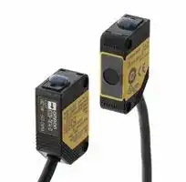


E3ZS-T81A
PHOTO SENSOR, THROUGH BEAM, 3M, PNP
- Manufacturer: OMRON INDUSTRIAL AUTOMATION
- Product type:
- SVHC: To Be Advised
- Product Range: E3Z Series
- Sensing Method: Through Beam
- Connection Method: Cable
- Sensing Range Max: 3m
- Sensor Output Type: PNP
- Supply Voltage DC Max: 24V
- Supply Voltage DC Min: 12V
| Delivery and price | |
|---|---|
| Units per pack | 50 |
| Price | 255.81 € |
| Current stock | 10+ |
| Lead time | 30 days |
**Single-beam Safety Sensor E3ZS/E3FS**

CSM_E3ZS_E3FS_DS_E_10_4

## **Detects Intrusions into Hazardous Areas with a Single Beam and Complies with International Safety Standards.**

**==> picture [161 x 7] intentionally omitted <==**

**----- Start of picture text -----**<br>
E3FS E3ZS<br>**----- End of picture text -----**<br>


Be sure to read the _“Safety Precautions”_ on page 13.

## **Features**

For the most recent information on models that have been certified for safety standards, refer to your OMRON website.

**Note:** Manufacturing of the E3FS listed in this datasheet was discontinued at the end of August 2016.

## **Connect to a G9SP to Create a Type 2 Safety Sensor**

**==> picture [23 x 7] intentionally omitted <==**

**----- Start of picture text -----**<br>
G9SP<br>**----- End of picture text -----**<br>


**==> picture [219 x 7] intentionally omitted <==**

**----- Start of picture text -----**<br>
E3ZS  E3FS  E3FS<br>**----- End of picture text -----**<br>


## **Application Examples**

## **For gaps in small-sized equipment**

## **Protect personnel from the hazards of gaps in small-sized equipment or of semi-automated machinery.**

The E3ZS is a Human Body Detection Sensor (Type 2) for production equipment. Make sure to use it in combination with an G9SP Safety Controller.

When used by itself, the E3ZS conforms to PLc/Safety Category 1 (EN ISO13849-1). No particular safety restrictions apply to the G9SP when used by itself, except the inability to use in human detection safety applications. We recommend using it in Light ON mode and using it with error detection via test input.

## **Note:** Test Input

Use this function to enable the emitter of E3ZS to be turned ON/OFF from outside. It is possible to detect a number of E3ZS errors by monitoring the status of the test input and the E3ZS output signal.

**For gaps in small to medium-sized equipment**

## **Use as a safety measure for protection from hazardous gaps or as guards for medium-sized equipment.**

The E3FS is a Human Body Detection Sensor (Type 2) for production equipment. Make sure to use it in combination with a G9SP Safety Controller.

**1**

**E3ZS/E3FS**

## **Ordering Information**

## **Sensors**

|**Sensor**<br>**method**|**Appearance**<br>~~a~~|**Case**<br>**material**|**Sheath**<br>**material**|**Connection**<br>**method**|**Sensing distance**|**Sensing distance**|**Sensing distance**|**Sensing distance**|**Sensing distance**|**Output**|**Model**|
|---|---|---|---|---|---|---|---|---|---|---|---|
|Through-<br>beam<br>~~C4~~|~~ei~~|Polybutylene<br>terephthalate<br>~~ei~~|PVC<br>~~|~~<br>~~eS~~|Pre-wired<br>cable (2 m)<br>~~eS~~||0.2 to 3 m|0.2 to 3 m|||PNP|**E3ZS-T81A**|
||~~ei~~<br>~~eS~~<br>~~C4~~|ABS<br>~~ei~~<br>~~eS~~<br>~~C4~~|||~~eS~~|~~eS~~|~~eS~~||10 m<br>~~eS~~<br>~~eel~~||**E3FS-10B4 2M***|
||||||~~eS~~|~~eS~~|~~eS~~|10 m<br>~~eS~~|10 m<br>~~eS~~|||
||||||~~eS~~<br>~~eel~~|~~eS~~<br>~~eel~~|~~eS~~<br>~~eel~~|||||
||~~ei~~<br>~~eS~~<br>~~C4~~|Brass<br>~~ei~~<br>~~eS~~<br>~~C4~~|---<br>~~|~~<br>~~eS~~|M12<br>connector<br>~~eS~~|~~eS~~<br>~~eel~~|~~eS~~<br>~~eel~~|~~eS~~<br>~~eel~~||10 m<br>~~eS~~<br>~~eel~~||**E3FS-10B4-M1-M***|
||||||~~eel~~|~~eel~~|~~eel~~|10 m<br>~~eel~~|10 m<br>~~eel~~|||
||||||~~eel~~|~~eel~~|~~eel~~|||||


## **Controller**

## **Safety Controller G9SP Series**

|**Name**|**No. of I/O points**|**No. of I/O points**|**No. of I/O points**|**No. of I/O points**|**Unit version**|**Model**|
|---|---|---|---|---|---|---|
||**Safety**<br>**inputs**|**Test**<br>**outputs**|**Safety outputs**|**Standard**<br>**outputs**|||
|Safety Controller|10|4|Semiconductor outputs: 4|4|Ver.2.0|**G9SP-N10S**|
||10|6|Semiconductor outputs: 16|---||**G9SP-N10D**|
||20|6|Semiconductor outputs: 8|---||**G9SP-N20S**|


**Note:** For details, refer to the G9SP Catalog (F090).

## **Accessories**

## **Branch Connector**

|**Appearance**||**Model**|
|---|---|---|
||**F39-CN3**||


## **Sensor Mounting Bracket (for E3FS)**

|**Appearance**||**Model**|
|---|---|---|
||**Y92E-B18**||


## **Sensor Mounting Bracket (for E3ZS)**

|**Appearance**||**Model**|
|---|---|---|
||**E39-L104**||


**2**

**E3ZS/E3FS**

## **Mutual Interference Prevention Filter (for E3ZS)**

||**Dimensions**|**Dimensions**|**Model**|**Quantity**|**Remarks**|
|---|---|---|---|---|---|
|||0.2<br>1<br>4.9<br>10.8<br>7.4|**E39-E11**|2 per Emitter and<br>Receiver (4 total)|For use with E3ZS-T81A. This filter prevents mutual interference by<br>changing the direction of polarized light of the 2 adjacent Emitter/<br>Receivers. However, when the filter is attached, the maximum<br>sensing distance of the E3ZS is reduced to 1.5 m.|
|||7.4||||
|||||||
||11.2<br>31.4|||||
|||||||
|||||||


## **Cables with Connectors (Socket and Plug) on Both Ends (for extension)**

|**Type**|**Cable connection direction**|**Cable length L**<br>**(m)**|**DC**|**UL standard**|
|---|---|---|---|---|
||||**Model**||
|Fire-retardant, robot cable|Straight/straight|1|**XS2W-D421-C81-F**|●|
|||2|**XS2W-D421-D81-F**||
|||5|**XS2W-D421-G81-F**||
|||10|**XS2W-D421-J81-F**||
||Right angle/right angle|2|**XS2W-D422-D81-F**||
|||5|**XS2W-D422-G81-F**||
||Straight/right angle|2|**XS2W-D423-D81-F**||
|||5|**XS2W-D423-G81-F**||
||Right angle/straight|2|**XS2W-D424-D81-F**||
|||5|**XS2W-D424-G81-F**||


**Note:** Extend the cable under the following conditions.

- Overall cable length for both an E3FS Receiver connected to an G9SP and the Emitter connected to the G9SP must be within 50 m.

- Overall cable length for both an E3ZS Receiver connected to an G9SP and the Emitter connected to the G9SP must be within 100 m.

## **Cables with Connector (Socket) on One End (connecting to G9SP)**

|**Type**|**Cable connection direction**|**Cable length L**<br>**(m)**|**DC**|**UL standard**|
|---|---|---|---|---|
||||**Model**||
|Fire-retardant, robot cable|Straight|1|**XS2F-D421-C80-F**|●|
|||2|**XS2F-D421-D80-F**||
|||5|**XS2F-D421-G80-F**||
|||10|**XS2F-D421-J80-F**||
||Right angle|1|**XS2F-D422-C80-F**||
|||2|**XS2F-D422-D80-F**||
|||5|**XS2F-D422-G80-F**||
|||10|**XS2F-D422-J80-F**||


**Note:** Extend the cable under the following conditions.

- Overall cable length for both an E3FS Receiver connected to an G9SP and the Emitter connected to the G9SP must be within 50 m.

- Overall cable length for both an E3ZS Receiver connected to an G9SP and the Emitter connected to the G9SP must be within 100 m.

## **Connector Plug Assemblies, Solder Type** *

|**Applicable cable diameter**<br>**(mm)**|**Cable connection**<br>**direction**|**Connection**<br>**method**|**Model**|
|---|---|---|---|
|3 dia. (3 to 4 dia.)|Straight|Solder|**XS2G-D425**|
||Right angle||**XS2G-D426**|


- Use when connecting an E3ZS-T81A or E3FS-10B4 2M to an F39-CN3 Branch Connector.

## **Connector Plug Assemblies, Screw-on Type** *

|**Applicable cable diameter**<br>**(mm)**|**Cable connection**<br>**direction**|**Connection**<br>**method**|**Model**|
|---|---|---|---|
|3 dia. (3 to 4 dia.)|Straight|Screw-on|**XS2G-D4S5**|
||Right angle||**XS2G-D4S6**|


- Use when connecting an E3ZS-T81A or E3FS-10B4 2M to an F39-CN3 Branch Connector.

**3**

**E3ZS/E3FS**

## **System Configuration**

**==> picture [291 x 109] intentionally omitted <==**

**----- Start of picture text -----**<br>
Emitter   Receiver<br>(E3FS-10B4-M1-M)<br>Branch Connector for the E3FS<br>Cable with Connectors on Both Ends Cable with Connectors on Both Ends<br>(XS2W-D42@-@81-@) (F39-CN3)  (XS2W-D42@-@81-@)<br>A  B<br>C<br>**----- End of picture text -----**<br>


**==> picture [114 x 13] intentionally omitted <==**

**----- Start of picture text -----**<br>
Cables with Connector (Socket) on One End<br>(XS2F-D42@-@80-@)<br>**----- End of picture text -----**<br>


**==> picture [121 x 98] intentionally omitted <==**

|**Wire color for XS2F-D42**@**-**@**80-**@<br>White<br>Black<br>Blue<br>Brown|**Function**|
|---|---|
||Test input|
||Control input|
||0V|
||24V|


**Note:** The mode selection input wire of the E3FS is connected to 24 V inside the F39-CN3. Light-ON operation is performed.

Safety Controller (G9SP)

**==> picture [281 x 198] intentionally omitted <==**

**----- Start of picture text -----**<br>
Cable with Connector (Socket)<br>on One End<br>(XS2F-D42@-@80-@)<br>Connector Plug Assembly  Connector Plug Assembly<br>(XS2G-D4@@) (XS2G-D4@@)<br>Branch Connector for<br>the E3FS<br>(F39-CN3)<br>Receiver   Emitter<br>(E3FS-10B4 2M)<br>Receiver   or  Emitter<br>(E3ZS-T81A)<br>C<br>B  A<br>**----- End of picture text -----**<br>


**4**

**E3ZS/E3FS**

## **Specifications**

## **E3ZS/E3FS**

|**Item**<br>**Model**|**Item**<br>**Model**|**E3ZS-T81A**|**E3FS-10B4 2M**|**E3FS-10B4-M1-M**|
|---|---|---|---|---|
|**Sensor type**||Through-beam models|||
|**Safety category**||See Applicable standards.|||
|**Standard sensing object**||Opaque object: 18 mm in diameter orgreater|Opaque object: 11 mm in diameter orgreater||
|**Lens diameter**||Diameter 6.7 mm / diameter 9 mm|||
|**Sensing distance**||0.2 to 3 m|0 to 10 m||
|**Response time (under stable**<br>**light incident condition)**||1.0 ms (E3ZS only)|2.0 ms (E3FS only)||
|**Startup waiting time**||100 ms|||
|**Power supply voltage (Vs)**||12 to 24 VDC±10%(ripplep-p10% max.) *1|24 VDC±10%(ripplep-p10% max.) *1||
|**Current consumption**<br>**(no load)**||Emitter: 15 mA max.<br>Receiver: 20 mA max.|Emitter: 50 mA max.<br>Receiver: 25 mA max.||
|**Light source (emitted**<br>**wavelength)**||Red LED (660 nm)|Infrared LED (870 nm)||
|**Effective aperture angle**<br>**(EAA)**||±5°(at 3 m)|||
|**Control output (OSSD)**||PNP transistor output, load current: 100 mA max.,<br>Residual voltage: 1 V max., (when load current is<br>less than 10 mA), Residual voltage: 2 V max. (when<br>load current is between 10 mA and 100 mA)<br>(except for voltage dropdue to cable extension) *1|PNP transistor output, load current: 100 mA max.,<br>Residual voltage: 2 V max.<br>(except for voltage drop due to cable extension)*1||
|**Output operation mode**||Light-ON*2|||
|**Input voltage**||22.5 to 24 VDC: Emitter OFF (source current: 3 mA max.)<br>Open or 0 to 2.5 V: Emitter ON (leakage current: 0.1<br>mA max.) *1|21.5 to 24 VDC: Emitter OFF (source current: 3 mA max.)<br>Open or 0 to 2.5 V: Emitter ON (leakage current: 0.1 mA<br>max.) *1||
|**Indicators**||Emitter: Emitting (orange);<br>Receiver: Operation(orange), Stable(green)|Emitter: Emitting (orange);<br>Receiver: Output OFF(red), Output ON(green)||
|**Test functions**||External test(light emission stopfunction bytest input)|||
|**Connection method**||Pre-wired cable(2 m)||M12 connector|
|**Protective circuits**||Power supply/output reverse connection<br>protection, load short-circuitprotection|Output reverse connection protection, load short-circuited<br>protection||
|**Ambient temperature**||Operating:−10 to 55°C<br>Storage:−10 to 70°C<br>(with no icingor condensation)|Operating:−20 to 55°C<br>Storage:−30 to 70°C<br>(with no icingor condensation)||
|**Ambient humidity**||Operating: 35% to 85%, storage: 35% to 95%(with no icingor condensation)|||
|**Ambient operating light**<br>**intensity**||Incandescent lamp: 3000 lx max (light intensity on the receiver surface).<br>Sunlight: 10,000 lx max(light intensityon the receiver surface).|||
|**Insulation resistance**||20 MΩmin.(at 500 VDC)|||
|**Dielectric strength**||1000 VAC 50/60 Hz 1 min|||
|**Degree ofprotection**||IP67(IEC standard)|||
|**Vibration**<br>**resistance**|**Operating limit**|10 to 55 Hz, double amplitude: 0.7 mm, 50 min each in the X, Y, and Z directions|||
||**Malfunction**|10 to 55 Hz, double amplitude: 1.5 mm, 2 h each in the X, Y, and Z directions|||
|**Shock**<br>**resistance**|**Operating limit**|100 m/s2, 1000 times in the X, Y, and Z directions|||
||**Malfunction**|500 m/s2, 3 times each in the X, Y, and Z directions|||
|**Material**||Case: Polybutylene terephthalate|Case: ABS|Case: Brass|
|**Weight (packed state)**||Approx. 120 g (for one set including 2-m cable)|Approx. 150 g (for one set<br>including2-m cable)|Approx. 125 g (for one set<br>includingonlySensor)|
|**Accessories**||Operation manual|Operation manual, nuts for mounting Emitter/Receiver<br>(2 each)||
|**Applicable**<br>**standards**|**Sensor only**|IEC 60947-5-3 (PDDB)<br>EN ISO13849-1(PLc/SafetyCategory1)|---||
||**Sensor**<br>**connected to**<br>**G9SP**|IEC(EN)61496-1 Type2 ESPE*3<br>IEC (EN)61496-2 Type2 AOPD*4<br>EN ISO13849-1(PLc/SafetyCategory2)|||
|**Switching element category**<br>**(from IEC60947-5-3)**||DC13 (control of electromagnetic load)|---||


*1. Connect the Sensor to an G9SP to use it as a safety device or as part of a safety system.

*2. Depending on the wiring, this may turn ON when light is interrupted.

For your safety, be sure to connect the pink receiver wire (mode selection input) to 24 VDC to turn ON when light is incident.

*3. Electro-Sensitive Protective Equipment

*4. Active Opto-electronic Protective Device

**5**

**E3ZS/E3FS**

## **Connections**

## **Circuit Diagram Example**

This section describes connecting an OMRON Safty Controller G9SP.

The OSSD 24-VDC semiconductor output from the Single Beam Safety Sensor is input.

**==> picture [249 x 152] intentionally omitted <==**

**----- Start of picture text -----**<br>
— ><br>Single Beam<br>— »<br>Safety Sensor<br>—_ ><br>L1<br>T3<br>Si0 L2<br>24  VDC L1 + L2 ≤ 100 m<br>0 V<br>Receiver<br>Light transmitter<br>)(Brown<br>24 V (Brown) 0 V (Blue) Mode (Pink) 24 V  0 V (Blue)<br>Test input (Pink) Control output (Black)<br>**----- End of picture text -----**<br>


## **G9SP Configurator Setting Example**

- **Note: 1.** Only one E3ZS/E3FS Single Beam Safety Sensor can be connected to a G9SP-series Safety Controller with unit version 1.0 or unit version 1.1.

      - The maximum number of E3ZS/E3FS Single Beam Safety Sensors that can be connected to a G9SP-series Safety Controller with unit version 2.0 or later is as follows:

      - G9SP-N10S: 4 (1 Sensor ⋅ 4 systems)

      - G9SP-N10D/20S: 6 (1 Sensor ⋅ 6 systems)

   **2.** The total wiring length (L1 + L2 in the above figure) for the E3ZS Single Beam Safety Sensor must be 100 m or less and  for the E3FS Single Beam Safety Sensor must be 50 m or less.

   **3.** The E3ZS/E3FS Single Beam Safety Sensor can be used in a Safety Category 2 or lower, or PLc or lower application. It cannot be used in a Safety Category 3 or higher, or PLd or higher application.

   **4.** If you use more than one Single Beam Safety Sensor, it may not be possible to detect short circuits between wires. To satisfy safety category 2, you must protect the cables to the Single Beam Safety Sensors from external damage. Use ducts, separate the cables for each system, or implement other measures to protect the cables from external damage when you connect the Single Beam Safety Sensors. You can also provide protection against short circuits by using special cables (XS2F).

   **5.** The test period for a Single Beam Safety Sensor test is as given below. Use the value as reference to determine conformance with standards for your system.

      - G9SP-N10S: 112 × Cycle time (ms)

      - G9SP-N10D/20S: 168 × Cycle time (ms)

**6**

**E3ZS/E3FS**

## **I/O Circuit Diagrams**

## **E3ZS**

## **Circuit Diagrams (E3ZS-T81A with PNP Output)**

Output mode: ON when light is incident (Light ON)

**==> picture [299 x 205] intentionally omitted <==**

**----- Start of picture text -----**<br>
I/O circuit<br>indicatorStability Operationindicator Brown *1<br>1 Connects to the 24 VDC<br>terminal.<br>Green 2 *2 *1<br>Receiver Orange circuitMain  4PinkBlack Connects to the control output terminal.<br>*1<br>3 Connects to the 0 V<br>terminal.<br>Blue<br>Brown *1<br>Emissionindicator 1 Connects to the 24 VDC terminal.<br>*1<br>Emitter Orange circuitMain  4Pink Connects to the test input terminal.<br>*3<br>*1<br>Blue Connects to the 0 VDC<br>3 terminal.<br>**----- End of picture text -----**<br>


## **Timing Charts Output Modes and Timing Char**

**==> picture [42 x 54] intentionally omitted <==**

**----- Start of picture text -----**<br>
Light incident<br>Light interrupted<br>Operation  ON<br>indicator<br>(orange) OFF<br>Control  ON<br>output OFF<br>**----- End of picture text -----**<br>


**==> picture [45 x 50] intentionally omitted <==**

## **Emitter Timing Chart**

**==> picture [42 x 56] intentionally omitted <==**

**----- Start of picture text -----**<br>
Test input ON<br>OFF<br>Emission ON<br>OFF<br>Operation  ON<br>indicator<br>(orange) OFF<br>**----- End of picture text -----**<br>


**==> picture [64 x 50] intentionally omitted <==**

- *1. When using in Safety Category 2 or Type 2 ESPE configurations, make sure all terminals on a safety controller are properly connected. See the safety controller operation manual for details.

- *2. Make sure to connect the pink wire (mode selection input 2) to 24 VDC.

- *3. Make sure to connect to the 0V terminal when the E3ZS is not connected to a

   - safety controller and the test input is not used.

## **E3FS**

**Circuit Diagrams (E3FS-10B4** @@@ **with PNP Output)** Output mode: ON when light is incident (Light ON).

**==> picture [299 x 205] intentionally omitted <==**

**----- Start of picture text -----**<br>
I/O circuit<br>Lit when  Lit when  *1<br>ON OFF 1Brown Connects to the 24 VDC terminal.<br>Green Red 2 *2 *1<br>Receiver circuitMain  Internal  4BlackPink Connects to the control output terminal.<br>resistance<br>of the output  *1<br>IC 3 Blue Connects to the 0 V terminal.<br>*1<br>Lit when emitting 1Brown Connects to the 24 VDC terminal.<br>*1<br>Emitter Orange circuitMain  4 Pink Connects to the test input terminal.<br>*3<br>*1<br>Blue Connects to the 0 V<br>3 terminal.<br>**----- End of picture text -----**<br>


## **Timing Charts Output Modes and Timing Chart**

**==> picture [108 x 51] intentionally omitted <==**

**----- Start of picture text -----**<br>
Light incident<br>Light interrupted<br>Operation  Green<br>indicator Red<br>Control  ON<br>output OFF<br>**----- End of picture text -----**<br>


## **Emitter Timing Chart**

**==> picture [42 x 56] intentionally omitted <==**

**----- Start of picture text -----**<br>
Test input ON<br>OFF<br>Emission ON<br>OFF<br>Operation  ON<br>indicator<br>(orange) OFF<br>**----- End of picture text -----**<br>


**==> picture [64 x 50] intentionally omitted <==**

- *1. Make sure all terminals on the G9SP are properly connected. Do not connect the terminals to another Module. See the G9SP operation manual for details.

- *2. Make sure to connect the pink wire (mode selection input 2) to 24 VDC.

- *3. Make sure to connect to the 0V terminal when the E3FS is not connected to an G9SP and the test input is not used.

**Note:** The E3FS-10B4 @@@ functions as a standalone Sensor when it is connected as shown in the wiring diagram above. However, it is certified a Type 2 Safety Sensor when it is properly connected to the B1 Module of the G9SP. This also means it must be properly connected to an G9SP to use it as part of a safety system.

**7**

**E3ZS/E3FS**

**Engineering Data**

## **E3ZS**

**Parallel Operating Range**

## **Excess Gain Ratio**

**Mutual Interference Range**

**==> picture [508 x 355] intentionally omitted <==**

**----- Start of picture text -----**<br>
200 Emitter 200 Emitter 100<br>Receiver Receiver<br>150 Y 150 Y<br>X X<br>100 100<br>10<br>50 50<br>0 0<br>−50 −50<br>1<br>−100 −100<br>−150 −150<br>−2000 1 2 3 4 5 6 −2000 1 2 3 4 5 6 0.10 2 4 6 8 10 12<br>Distance X (m) Distance X (m) Distance (m)<br>E3FS<br>Parallel Operating Range Mutual Interference Range Excess Gain Ratio<br>600 800 10<br>Emitter<br>Y 600 Y 9<br>400 Emitter<br>X X 8<br>Receiver 400 Receiver<br>7<br>200<br>200<br>6<br>0 0 5<br>−200 4<br>−200<br>3<br>−400<br>−400 2<br>−600 1<br>−600 −800 0<br>0 2 4 6 8 10 12 0 2 4 6 8 10 12 0 5 10 15 20 25 30<br>Distance X (m) Distance X (m) Distance (m)<br>Operating position Y (mm) Mutual interference range Y (mm) Excess gain ratio (times)<br>Operating position Y (mm) Mutual interference range Y (mm)  Excess gain ratio (times)<br>**----- End of picture text -----**<br>


## **E3FS**

## **Parallel Operating Range**

**8**

**E3ZS/E3FS**

**(Unit: mm)**

## **Dimensions**

## **Sensors**

## **Pre-wired Cable with ABS Resin Case E3ZS-T81A**

**==> picture [147 x 136] intentionally omitted <==**

**----- Start of picture text -----**<br>
10.8 10.4 3.54<br>Operation indicator (Receiver only) 8<br>Emitting indicator (Emitter only) 20<br>Stability indicator (Receiver only)<br>2.1<br>6.7 dia. 17<br>Lens<br>Beam<br>my 31 25.4 [fr<br>15.5<br>2-M3<br>**----- End of picture text -----**<br>


Vinyl-insulated round cord with four Receiver conductors and three Emitter conductors, 4 dia. (cross sections of conductors: 0.2 mm[2] , insulation system: 1.1 mm dia.) Standard length: 2 m

## **Pre-wired Cable with ABS Resin Case E3FS-10B4 2M**

**==> picture [60 x 82] intentionally omitted <==**

**----- Start of picture text -----**<br>
Lens surface<br>22<br>24<br>9 dia.<br>**----- End of picture text -----**<br>


3.2 64.9 42.3 37 * 4 dia. 16.4 dia. ~~P~~ 5 M18 × 1 Operation indicator ~~I~~ * Vinyl-insulated round cord with four Receiver conductors and three Emitter 4 conductors, 4 dia. (cross sections of ~~:~~ 8 conductors: 0.2 mm[2] , insulation system: 1.1 mm dia.) 4.8 dia.

**Connector with Metal Case E3FS-10B4-M1-M**

76 65.5 Lens surface 42.3 24 37 27.7 ~~al M~~ 12 × 1 16.4 dia. M18 × 1 Operation indicator 9 dia. 4 ~~eae~~ 4.8 dia.

**9** omrRon ~~a~~

**E3ZS/E3FS**

## **Accessories (Order Separately)**

**Branch Connector F39-CN3**

**==> picture [502 x 156] intentionally omitted <==**

**----- Start of picture text -----**<br>
Branch Connector 50.6<br>F39-CN3 24.6 *<br>2<br>14 3<br>@ = g ~ kW<br>29<br>Wiring Diagram<br>4 4<br>3 3<br>2 2<br>A 1 | 1 s<br>14<br>1 2 3 4 2 3 * The molded part B of the Connector is black.<br>Sensor Mounting Bracket (for E3FS)<br>Y92E-B18 32±0.2<br>3 14<br>2<br>**----- End of picture text -----**<br>


**==> picture [356 x 254] intentionally omitted <==**

**----- Start of picture text -----**<br>
WoL 1 7 max.<br>4 7 max .<br>7<br>30<br>Material: Plastic<br>18 dia. Hexagonal bolt: M5 x 32<br>Sensor Mounting Bracket (for E3ZS) R1.7 R1.7 3.4<br>E39-L104 14° 5.8 12.5  [(13.7)]<br>R20<br>R1 3.4 6 4.5<br>29<br>R3.5 1 6<br>3.5<br>R25.4<br>(39) 37.8<br>3.2<br>Material: Stainless steel (SUS304) 8.8<br>R1 L. R1.6 il 10°<br>Two, 3.2 dia.<br>**----- End of picture text -----**<br>


**10**

**E3ZS/E3FS**

**Cables with Connectors (Socket and Plug) on Both Ends (for extension) XS2W-D421-C81-F (L=1m) XS2W-D421-D81-F (L=2m) XS2W-D421-G81-F (L=5m) XS2W-D421-J81-F (L=10m)**

**XS2W-D422-D81-F (L=2m) XS2W-D422-G81-F (L=5m)**

**XS2W-D423-D81-F (L=2m) XS2W-D423-G81-F (L=5m)**

**XS2W-D424-D81-F (L=2m) XS2W-D424-G81-F (L=5m)**

**==> picture [261 x 339] intentionally omitted <==**

**----- Start of picture text -----**<br>
6 dia.<br>14.9 dia. 14.9 dia.<br>40.7 44.7<br>L<br>14.9 dia.<br>28.3 6 dia. 32.3<br>25.3 25.3<br>L<br>14.9 dia.<br>6 dia. 32.3<br>14.9 dia.<br>40.7 25.3<br>L<br>28.3 6 dia.<br>1 4.9 dia.<br>25.3 44.7<br>L<br>**----- End of picture text -----**<br>


Sheath material: PVC

**11**

**E3ZS/E3FS**

**==> picture [498 x 246] intentionally omitted <==**

**----- Start of picture text -----**<br>
Cables with Connector (Socket) on One End (connecting to G9SP)<br>XS2F-D421-C80-F (L=1m) 6 dia.<br>XS2F-D421-D80-F (L=2m)<br>XS2F-D421-G80-F (L=5m) 14.9 dia.<br>XS2F-D421-J80-F (L=10m)<br>40.7 30 5<br>L  50<br>M12  45°<br>5 dia.<br>XS2F-D422-C80-F (L=1m) L<br>XS2F-D422-D80-F (L=2m) 25.3 6 dia.<br>XS2F-D422-G80-F (L=5m)<br>XS2F-D422-J80-F (L=10m)<br>28.3  30 5<br>50<br>M12<br>5 dia.<br>45°  Sheath material: PVC<br>**----- End of picture text -----**<br>


## **Connector Plug Assemblies, Solder Type**

## **XS2G-D425**

## **XS2G-D426**

**==> picture [199 x 144] intentionally omitted <==**

**----- Start of picture text -----**<br>
45°  5 dia.  M12<br>14.9 dia. 14.2 dia.<br>47.1<br>45°  5 dia.  35.7<br>14.9 dia.  M12 × 1<br>23<br>**----- End of picture text -----**<br>


## **Connector Plug Assemblies, Screw-on Type**

**XS2G-D4S5**

**==> picture [91 x 54] intentionally omitted <==**

**==> picture [213 x 48] intentionally omitted <==**

**----- Start of picture text -----**<br>
M12 × 1 58.7<br>20 dia.14.9 dia. 14 dia.<br>**----- End of picture text -----**<br>


## **XS2G-D4S6**

**==> picture [89 x 56] intentionally omitted <==**

**==> picture [177 x 94] intentionally omitted <==**

**----- Start of picture text -----**<br>
M12 × 1 39.7<br>20 dia. 14.9 dia.<br>39.6<br>14 dia.<br>**----- End of picture text -----**<br>


**12**

**E3ZS/E3FS**

## **Safety Precautions**

## **<Single-beam Safety Sensor E3ZS/E3FS>**

## ! **WARNING**

G9SP is the only Controller that can be used for the E3ZST81A/E3FS-10B4 @@@ (type 2). Normal operation may not be possible if another Single-beam Sensor Controller is used.

**==> picture [34 x 78] intentionally omitted <==**

The Sensor cannot be used as part of a safety system when the mode selection input of the Single-beam Safety Sensor Receiver is connected to 0 V because the Sensor will turn ON when light is interrupted (Dark ON). Be sure to connect the mode selection input to 24 VDC if you want the Sensor to turn ON when light is incident (Light ON).

Refer to the website at: http://www.ia.omron.com/ for calculating the Safety distance.

## **Preventing Mutual Interference**

Observe the following items during installation to prevent Single-beam Safety Sensors from interfering with each other or with Safety Light Curtains.

- Leave adequate space between the Sensors during installation. (Refer to the instruction manuals for the E3ZS/E3FS.)

- Use baffle plates to separate Sensors.

- Alternate Emitters and Receivers during installation. (See the figure below.)

Emitter Receiver Receiver Emitter Emitter Receiver Receiver Emitter

Check for mutual interference between Single-beam Safety Sensors or Safety Light Curtains connected to the same or different Control Units before finalizing placement and starting normal operation.

## ! **WARNING**

When installing multiple Safety Light Curtains, Multi-beam Safety Sensors, and Single-beam Safety Sensors, take necessary steps to prevent mutual interference. Otherwise detection may fail and serious injury may result.

**13**

## Terms and Conditions Agreement

## Read and understand this catalog.

Please read and understand this catalog before purchasing the products.  Please consult your OMRON representative if you have any questions or comments.

## Warranties.

(a) Exclusive Warranty. Omron’s exclusive warranty is that the Products will be free from defects in materials and workmanship for a period of twelve months from the date of sale by Omron (or such other period expressed in writing by Omron). Omron disclaims all other warranties, express or implied.

(b) Limitations. OMRON MAKES NO WARRANTY OR REPRESENTATION, EXPRESS OR IMPLIED, ABOUT NON-INFRINGEMENT, MERCHANTABILITY OR FITNESS FOR A PARTICULAR PURPOSE OF THE PRODUCTS. BUYER ACKNOWLEDGES THAT IT ALONE HAS DETERMINED THAT THE

PRODUCTS WILL SUITABLY MEET THE REQUIREMENTS OF THEIR INTENDED USE.

Omron further disclaims all warranties and responsibility of any type for claims or expenses based on infringement by the Products or otherwise of any intellectual property right. (c) Buyer Remedy. Omron’s sole obligation hereunder shall be, at Omron’s election, to (i) replace (in the form originally shipped with Buyer responsible for labor charges for removal or replacement thereof) the non-complying Product, (ii) repair the non-complying Product, or (iii) repay or credit Buyer an amount equal to the purchase price of the non-complying Product; provided that in no event shall Omron be responsible for warranty, repair, indemnity or any other claims or expenses regarding the Products unless Omron’s analysis confirms that the Products were properly handled, stored, installed and maintained and not subject to contamination, abuse, misuse or inappropriate modification. Return of any Products by Buyer must be approved in writing by Omron before shipment. Omron Companies shall not be liable for the suitability or unsuitability or the results from the use of Products in combination with any electrical or electronic components, circuits, system assemblies or any other materials or substances or environments. Any advice, recommendations or information given orally or in writing, are not to be construed as an amendment or addition to the above warranty.

See http://www.omron.com/global/ or contact your Omron representative for published information.

## Limitation on Liability; Etc.

OMRON COMPANIES SHALL NOT BE LIABLE FOR SPECIAL, INDIRECT, INCIDENTAL, OR CONSEQUENTIAL DAMAGES, LOSS OF PROFITS OR PRODUCTION OR COMMERCIAL LOSS IN ANY WAY CONNECTED WITH THE PRODUCTS, WHETHER SUCH CLAIM IS BASED IN CONTRACT, WARRANTY, NEGLIGENCE OR STRICT LIABILITY. Further, in no event shall liability of Omron Companies exceed the individual price of the Product on which liability is asserted.

## Suitability of Use.

Omron Companies shall not be responsible for conformity with any standards, codes or regulations which apply to the combination of the Product in the Buyer’s application or use of the Product. At Buyer’s request, Omron will provide applicable third party certification documents identifying ratings and limitations of use which apply to the Product. This information by itself is not sufficient for a complete determination of the suitability of the Product in combination with the end product, machine, system, or other application or use. Buyer shall be solely responsible for determining appropriateness of the particular Product with respect to Buyer’s application, product or system. Buyer shall take application responsibility in all cases.

NEVER USE THE PRODUCT FOR AN APPLICATION INVOLVING SERIOUS RISK TO LIFE OR PROPERTY OR IN LARGE QUANTITIES WITHOUT ENSURING THAT THE SYSTEM AS A WHOLE HAS BEEN DESIGNED TO ADDRESS THE RISKS, AND THAT THE OMRON PRODUCT(S) IS PROPERLY RATED AND INSTALLED FOR THE INTENDED USE WITHIN THE OVERALL EQUIPMENT OR SYSTEM.

## Programmable Products.

Omron Companies shall not be responsible for the user’s programming of a programmable Product, or any consequence thereof.

## Performance Data.

Data presented in Omron Company websites, catalogs and other materials is provided as a guide for the user in determining suitability and does not constitute a warranty. It may represent the result of Omron’s test conditions, and the user must correlate it to actual application requirements. Actual performance is subject to the Omron’s Warranty and Limitations of Liability.

## Change in Specifications.

Product specifications and accessories may be changed at any time based on improvements and other reasons. It is our practice to change part numbers when published ratings or features are changed, or when significant construction changes are made. However, some specifications of the Product may be changed without any notice. When in doubt, special part numbers may be assigned to fix or establish key specifications for your application. Please consult with your Omron’s representative at any time to confirm actual specifications of purchased Product.

## Errors and Omissions.

Information presented by Omron Companies has been checked and is believed to be accurate; however, no responsibility is assumed for clerical, typographical or proofreading errors or omissions.

**In the interest of product improvement, specifications are subject to change without notice.**

## **OMRON Corporation**

## **Industrial Automation Company**

2016.8

**http://www.ia.omron.com/**

(c)Copyright OMRON Corporation 2016 All Right Reserved.
Updated at April 23, 2026
With a legacy spanning over 80 years, Omron Industrial Automation is a globally recognized leader in the manufacture of advanced industrial control and automation components. Renowned for their reliability and engineering excellence, Omron delivers comprehensive solutions that enhance efficiency, machine safety, and precision across a wide range of manufacturing environments. Our extensive portfolio of Omron products is heavily focused on their industry-leading sensing and switching technologies. We offer a vast selection of sensors, excelling specifically in high-performance proximity sensors, light sensors, and temperature sensors. Complementing this range are robust switching solutions, featuring a deep inventory of power relays, solid-state relays, safety relays, and essential relay accessories designed for demanding operational requirements. Beyond sensing and switching, Omron is highly regarded for its precision automation and process control equipment. Our selection features highly accurate temperature controllers, versatile process controllers, and sophisticated panel displays and instrumentation. To support these fundamental systems, we also supply dependable Omron power supplies, notably AC/DC converters, alongside vital connectivity components like DIN rail terminal blocks to ensure secure, efficient, and complete industrial setups.
About Novapart
Novapart is a B2B electronic component broker specialising in stock shortages and cost reduction. We source hard-to-find parts and identify compliant alternatives across a catalogue of 410,000+ components from 500+ manufacturers.
Learn more →Stock Shortage Specialist
When a component is unavailable, discontinued or has an unacceptable lead time, we tap into our network of vetted European and Asian distributors to source what you need — without compromising on quality or traceability.
Request a quote →Compliant Alternatives
We identify pin-to-pin, electrically equivalent substitutes that meet the same certifications (RoHS, AEC-Q100, REACH) as your original specification — validated against datasheets, not just part numbers. Often at a lower cost.
BOM Analysis service →