
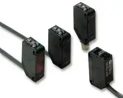


E3Z-D81 2M.
PHOTOSWITCH, DIFFUSE, 100MM, PNP
- Manufacturer: OMRON INDUSTRIAL AUTOMATION
- Product type:
- Approval Bodies:CE; Approval Category:UL Recognised; Current Consumption:30mA; External Depth:20mm; External Length / Height:31mm; External Width:10.4mm; IP / NEMA Rating:IP67; Lead Leng
- SVHC: No SVHC (17-Dec-2014)
- Product Range: E3Z Series
- Sensing Distance Max: 100mm
- Supply Voltage DC Max: 24VDC
- Supply Voltage DC Min: 12VDC
- Operating Temperature Max: 55°C
- Operating Temperature Min: -25°C
| Delivery and price | |
|---|---|
| Units per pack | 1 |
| Price | 99.09 € |
| Current stock | 10+ |
| Lead time | 30 days |
Photoelectric Sensor with Built-in Amplifier **E3Z** _For almost all binaray-detection applications, you can make selection from the E3Z_ Basic performance East-tooperate Globalization Reliability Environmental aid protection @0 **Features** Basic performance Through-beam Model Photoelectric Sen15m sor with built-in amplifier is applicable Retroreflective model Dimensions 10.4mm 20mm to a wide variety of (with MSR function) lines and ensures a 4m longer sensing distance than any other model. Diffuse-reflective model Lineup of models corre- ~~—~~ sponding to applications ~~‘~~ 1m ~~ag ant~~ (thin beam, transparent, | ~~[on]~~ grooved) Distance-setting model 0.2m ~~a~~

**E3Z**

1

## ~~Hs~~ Globalization

Meets a variety of international standards, thus allowing use in any country.

User-friendly Photoelectric Sensor takes all installation and on-site conditions into consideration.

Eliminates the influence of installation and on-site conditions, thus increasing the reliability of the line.

Global network with 191 offices in 38 countries.

A general-purpose connector ensures easy on-

**==> picture [62 x 8] intentionally omitted <==**

**----- Start of picture text -----**<br>
site installation!<br>**----- End of picture text -----**<br>


Highly water and dust-resistive and ensures easy installation in any location.

**==> picture [54 x 8] intentionally omitted <==**

**----- Start of picture text -----**<br>
IEC60529 IP67<br>**----- End of picture text -----**<br>


M8-connector, PNP output types that meet international standards are available.

The compact and space-saving model can be installed in any location.

**==> picture [176 x 283] intentionally omitted <==**

**----- Start of picture text -----**<br>
Our conventional product<br>me Je<br>i<br>oes ni<br>Resists common-mode noise generated by in-<br>verters.<br>120<br>rotooto ' f o t tadf<br>100 E3Z<br>80<br>60<br>40 O MRON 's conventional E 3V3<br>20<br>0<br>3 10 100<br>Inverter frequency (kHz)<br>Inverter noise voltage (V)<br>**----- End of picture text -----**<br>


Resists common-mode noise generated by inverters.

## [| Stability

E3Z-series reliability covers a wide range of object/ background combinations, and ensure stable detection regardless of workpiece color or glossiness.

Photoelectric Sensors

2

Photoelectric Sensor with Built-in Amplifier

**==> picture [77 x 19] intentionally omitted <==**

**----- Start of picture text -----**<br>
This ECO label is indicated on<br>products that meet the environmental<br>standards established by OMRON.<br>**----- End of picture text -----**<br>


**==> picture [381 x 263] intentionally omitted <==**

**----- Start of picture text -----**<br>
Earth-friendly energy-saving type.<br> Power Consumption Comparison<br>Conventional sensor<br>Saves energy *<br>Sn E3Z Approx.30 % less CG ><br>ih) © (|<br>* The above figure is based on measurement under normal operating conditions.<br>10-quantity packing reduces waste cartons. Packed in "combustible" polyethylene bags<br>free of Styrofoam. *<br>* If this bag is burned, dioxin hazardous to humans is<br>Recycled paper is used.ycled paper is used.cled paper is used.paper is used.aper is used.per is used.er is used. hardly generated.<br>Standard models provided with a 0.5-m cable are On-going elimination of materials containing<br>lead.<br>**----- End of picture text -----**<br>


**==> picture [193 x 170] intentionally omitted <==**

**----- Start of picture text -----**<br>
Recycled paper is used.ycled paper is used.cled paper is used.paper is used.aper is used.per is used.er is used.<br>Standard models provided with a 0.5-m cable are<br>available for the elimination of unnecessary ca-<br>ble length.<br>0.5m type<br>_<br>Unnecessary cable length<br>2m type<br>ae<br>**----- End of picture text -----**<br>


**==> picture [178 x 132] intentionally omitted <==**

**----- Start of picture text -----**<br>
Uses environmentally friendly, lead-free solder.<br>Pb<br>gy<br>eco<br>oR<br>**----- End of picture text -----**<br>


Ideal for detecting small objects with a small spot:

- Tiny objects as little as 0.1 mm in diameter can be detected with a

- 2.5-mm dia. spot.

- A thin beam enables detection through a gap or small hole.

- The small spot of light enables visual checking of sensing spot position.

**E3Z**

3

## Transparent PET bottles Le Stable detection of

Stable detection of thin-wall PET bottles adequate for recycling Standard-size transparent object sensor

- Uses OMRON's unique optical system ("Inner View") that can detect various shapes of PET bottles and transparent objects.

- Detects a wide range of bottles from 500-ml bottles to 2-l bottles, and from single bottles to sets of stocked bottles.

Grooved design eliminates the need for optical axis adjustment.

- ●Two-axis models also available..

Photoelectric Sensors

4

## Applications

E3Z-LS background and foreground suppression models Detecting covers on cosmetic products Detecting pastries on conveyor belts Detecting packaged chewing gum or candy

**==> picture [510 x 184] intentionally omitted <==**

**----- Start of picture text -----**<br>
Rt E3Z-L narrow beam models<br>Checking for straws Determining front/back or orientation of Detecting uneven joints<br>floppy disks<br>Front<br>Back<br>(Enlargement)<br>(Sensing at angle)<br>pe E3Z-B transparent object model<br>Transparent PET Bottle-related Detection Transparent PET Bottle related Detection Detection of films and glass plates<br>- One bottle - Multiple bottles (Stocker)<br>**----- End of picture text -----**<br>


**==> picture [510 x 24] intentionally omitted <==**

**----- Start of picture text -----**<br>
| E3Z-G grooved type model<br>Crane and automated warehouse conveyor table passage inspection and positioning.<br>**----- End of picture text -----**<br>


**==> picture [51 x 20] intentionally omitted <==**

**----- Start of picture text -----**<br>
Grooved-Type<br>Photoelectric Sensor<br>E3Z-G<br>**----- End of picture text -----**<br>


**E3Z**

5

## Ordering Information

|||||||||||||||||||
|---|---|---|---|---|---|---|---|---|---|---|---|---|---|---|---|---|---|
|Sensors||||||||||||||Red light|||Infrared light|
||||||||||||||<br>|||||
|Sensor type||Shape|||Connection method|Sensing distance|||||||Model|||||
||||||||||||||NPN output|||PNP output||
|Through-beam|||||Pre-wired models<br>(2 m)*3<br>|||15m|||||E3Z-T61<br>|||E3Z-T81<br>||
|||||||||||||||||||
||||||Connector type||||||||E3Z-T66|||E3Z-T86||
||||||Pre-wired models<br>(2 m)*3|||10m|||||E3Z-T61A|||E3Z-T81A||
|||||||||||||||||||
||||||Connector type||||||||E3Z-T66A|||E3Z-T86A||
|Retroreflective<br>model (with M.S.R.<br>function)||||*1|Pre-wired(2 m)*3|||4m<br>[100mm]|||*2||E3Z-R61|||E3Z-R81||
||||||Connector type||||||||E3Z-R66|||E3Z-R86||
|||||||||||||||||||
|Diffuse-reflective|||||Pre-wired models<br>(2 m)*3<br>|5 to 100 m||m (wide view||)|||E3Z-D61<br>|||E3Z-D81<br>||
||||||Connector type||||||||E3Z-D66|||E3Z-D86||
||||||Pre-wired models<br>(2 m)*3,*4|1m|||||||E3Z-D62|||E3Z-D82||
|||||||1||||||||||||
||||||Connector type||||||||E3Z-D67|||E3Z-D87||
|Thin beam type<br>reflective model|||||Pre-wired models<br>(2 m)*3|90±30mm|||||||E3Z-L61|||E3Z-L81||
||||||Connector type||||||||E3Z-L66|||E3Z-L86||
|Distance-settable|||||Pre-wired models<br>(2 m)*3||||||||E3Z-LS61|||E3Z-LS81||
|||||||40 mm<br>20 mm<br>200 mm<br>BGS (at min. setting)<br>BGS (at max. setting)<br>FGS (at max. setting)<br>FGS (at min. setting)<br>Incident<br>light level<br>threshold (fixed)||||||||||||
||||||Connector type||||||||E3Z-LS66|||E3Z-LS86||
|||||||||||||||||||
|Transparent PET<br>bottle type Retro- re-<br>flective model (with-<br>out M.S.R. function)||||*1|Pre-wired(2 m)*3|500mm [80|||||*2||E3Z-B61|||E3Z-B81||
||||||Connector type|||m]|||||E3Z-B66|||E3Z-B86||
||||||Pre-wired models<br>(2 m)*3|||100mm]|||*2||E3Z-B62|||E3Z-B82||
||||||||2m [|||||||||||
||||||Connector type||||||||E3Z-B67|||E3Z-B87||
|Grooved type<br>through-beam<br>model||||1<br>2<br>1<br>2|Pre-wired models<br>(2 m)*3|25mm|||||||E3Z-G61|||E3Z-G81||
||||||||||||||E3Z-G62|||E3Z-G82||
||||||Junction connector||||||||E3Z-G61-M3J|||E3Z-G81-M3J||
||||||||||||||E3Z-G62-M3J|||E3Z-G82-M3J||


*1. Not attached. Please purchase the optional reflector (9 types) according to your application.

*2. The sensing distance specified is possible when the E39-R1S used. Figure in parentheses indicate the minimum required distance between the Sensor and Reflector.

*3. Models provided with a 0.5-m cable are available. When ordering, specify the cable length by adding the code "0.5M" to the model number (e.g., E3Z-T61 0.5M).

*4. The connector joint type is available M12. Its model ends with -M1. (Example: E3Z-T61-M1J)

## Accessories (Order Separately)

Slits

|Slit width|Sensingdistance(typical)|Sensingdistance(typical)|Minimum sensing object (typical)|Model|Quantity|
|---|---|---|---|---|---|
||E3Z-T##|E3Z-T##A||||
|0.5 mm dia.|50 mm|35 mm|0.2 mm dia.|E39-S65A|One set (contains slits for both<br>the emitter and receiver)|
|1-mm dia.|200 mm|150 mm|0.4 mm dia.|E39-S65B||
|2-mm dia.|800 mm|550 mm|0.7 mm dia.|E39-S65C||
|0.5 x 10 mm|1 m|700 mm|0.2 mm dia.|E39-S65D||
|1 x 10 mm|2.2 m|1.5 m|0.5 mm dia.|E39-S65E||
|2 x 10 mm|5 m|3.5 m|0.8 mm dia.|E39-S65F||


Sensor I/O Connectors

|Size|Cable type|Shape||Cable length|Cable length|Model|
|---|---|---|---|---|---|---|
|M8|Standard cable|Straight||2 m|4-wire type|XS3F-M421-402-A|
|||||5 m||XS3F-M421-405-A|
|||L-shaped||2 m||XS3F-M422-402-A|
|||||5 m||XS3F-M422-405-A|
|M12 (for -M1J)||Straight||2 m|3-wire type|XS2F-D421-DC0-A|
|||||5 m||XS2F-D421-GC0-A|
|||L-shaped||2 m||XS2F-D422-DC0-A|
|||||5 m||XS2F-D422-GC0-A|


Photoelectric Sensors

6

## Reflectors

Not provided with retroreflective models

|Name<br>~~—~~|Sensingdistance(typical)*<br>~~—~~|Model<br>~~——~~|Quantity<br>~~——==~~|Remarks<br>~~—==~~|
|---|---|---|---|---|
|Reflectors<br>~~—~~<br>~~ee~~|3 m[100 mm] (Rated value)<br>~~—~~|E39-R1<br>~~——~~|1<br>~~——==~~|~~—==~~<br>~~ee~~|
||4 m[100 mm] (Rated value)<br>~~—~~|E39-R1S<br>~~——~~<br>~~a~~|1<br>~~——==~~<br>~~e~~||
||500 mm[80 mm]<br>~~—~~<br>~~ee~~|E39-R1S<br>~~——~~<br>~~ee~~<br>~~a~~|1<br>~~——==~~<br>~~ee~~<br>~~e~~|for E3Z-B#1/6<br>~~—==~~<br>~~ee~~<br>~~ee~~|
||2 m[100 mm]<br>~~ee~~|||for E3Z-B#2/7<br>~~ee~~<br>~~ee~~|
||5 m[100 mm]<br>~~ee~~|E39-R2<br>~~ee~~<br>~~a~~|1<br>~~ee~~<br>~~e~~|~~ee~~<br>~~ee~~<br>|
||2.5 m[100 mm]|E39-R9|1||
||3.5 m[100 mm]<br>|E39-R10<br>|1<br>||
|Fog preventing<br>~~ee~~|500 mm[80 mm]<br>|E39-R1K<br>|1<br>|for E3Z-B#1/6<br>|
||2 m[100 mm]<br>|||for E3Z-B#2/7<br>|
|Small reflector<br>~~eeeee~~|1.5 m[50 mm]<br>~~eee~~|E39-R3<br>~~eee~~|1<br>~~eee~~|~~eee~~|
|Tape Reflector<br>~~eeeee~~|700 mm[150 mm]<br>~~eee~~|E39-RS1<br>~~eee~~|1<br>~~eee~~||
||1.1 m[150 mm]<br>~~eee~~|E39-RS2<br>~~eee~~|1<br>~~eee~~||
||1.4 m[150 mm]<br>~~eee~~|E39-RS3<br>~~eee~~|1<br>~~eee~~||


## Mutual interference prevention filter

Sensing distance Shape/dimensions Model Quantity Remarks 10.87.4 4.9 Can be used with the through-beam E3Z-T##A. 1 2 sets each for emitThe arrow represents the polarizing direction. 3 m E39-E11 ters and receivers Changing the polarizing direction of the two adja31.4 11.2 (total of 4 pcs.) cent emitters and receivers prevents mutual in0.2 terference. ~~int,|~~

Mounting Brackets Shape Model Quantity Remarks Shape Model Quantity Remarks E39-L153 1 Mounting Brackets E39-L150 One set E39-L104 1 Sensor adjuster Easy mounting to alumi- ~~fh~~ num frame/rail of conveyor ~~ee~~ or like, easy adjustment. For left-to-right adjustment Horizontal type mounting E39-L43 1 E39-L151 One set bracket ~~eh~~ E39-L142 1 Horizontal type protective Sensor adjuster cover bracket Easy mounting to aluminum frame/rail of conveyor E39-L93 One set or like, easy adjustment. For vertical angle adjustE39-L44 1 Rear mounting bracket ment ~~eo | fe~~ Vertical protective cover E39-L98 1 Protective cover bracket E39-L144 1 bracket ~~Ce~~ Note: 1 .If a through-beam model is used, order two Mounting Brackets for the emitter and receiver respectively. 2 .For details, refer to the "Mounting bracket list".

**E3Z**

7

Rating/performance

||Sensor type|Through-beam|Through-beam|Retroreflective<br>model (with M.S.R.<br>function)|Diffuse-reflective|Diffuse-reflective|
|---|---|---|---|---|---|---|
||||||wide-beam||
|Model|NPN output|E3Z-T61/T66|E3Z-T61A/T66A|E3Z-R61/R66|E3Z-D61/D66|E3Z-D62/D67|
|Item|PNP output|E3Z-T81/T86|E3Z-T81A/T86A|E3Z-R81/R86|E3Z-D81/D86|E3Z-D82/D87|
|Sensing distance||15 m|10 m|4 m (100 mm) *<br>(When using the<br>E39-R1S)<br>3 m (100 mm) *<br>(When using the<br>E39-R1)|100 mm (White<br>paper 100 x 100<br>mm)|1 m (White paper<br>300 x 300 mm)|
|Setting range||---|||||
|Reflectivity characteristic||---|||||
|Spot Diameter||---|||||
|Standard sensing object||Opaque: 12-mm dia. min.||Opaque: 75-mm dia.<br>min.|---||
|Min. sensing object||---|||||
|Differential distance||---|||20% max. of sensing distance||
|Directional angle||Both emitter and<br>receiver: 3° to 15°|Both emitter and<br>receiver: 3° to 5°|2° to 10°|---||
|Light source (wave length)||Infrared LED<br>(860 nm)|Red LED<br>(700 nm)|Red LED<br>(680 nm)|Infrared LED<br>(860 nm)||
|Power supply voltage||12 to 24 VDC ±10%, ripple (p-p) : 10% max.|||||
|Current consumption||emitter: 15 mA receiver: 20 mA||30 mA max.|||
|Control output||Load power supply voltage 26.4 VDC max., load current 100 mA max. (residual voltage 1 V max.) Open<br>collector output type (depends on the NPN/PNP output format) Light-ON/Dark-ON switch selectable|||||
|BGS / FGS selection||---|||||
|Protective circuits||Protection from load short-circuit and<br>reversed power supply connection||Reverse polarity protection, output short-circuit protection,<br>mutual interference prevention|||
|Response time||Operation or reset: 1 ms max.|||||
|Sensitivity adjustment||Single-turn adjustment|||||
|Ambient illuminance||Incandescent lamp: 3,000 lux max. Sunlight 10,000 lux max.|||||
|Ambient temperature||Operating: -25°C to 55°C, Storage: -40°C to 70°C (with no icing or condensation)|||||
|Ambient humidity||Operating: 35% to 85% RH, Storage: 35% to 95% RH (with no icing or condensation)|||||
|Insulation resistance||20 MΩmin. at 500 VDC|||||
|Dielectric strength||1,000 VAC at 50/60 Hz for 1 minute|||||


* Values in parentheses indicate the minimum required distance between the sensor and reflector.

Photoelectric Sensors

8

## Rating/performance

|Diffuse-<br>reflective|Distance-<br>settable|Retro-reflective for PET bottles<br>(without MSR function)|Retro-reflective for PET bottles<br>(without MSR function)|Grooved-type|Grooved-type|
|---|---|---|---|---|---|
|narrow-beam|||wide-beam|||
|E3Z-L61/66|E3Z-LS61/66|E3Z-B61/66|E3Z-B62/67|E3Z-G61|E3Z-G62|
|E3Z-L81/86|E3Z-LS81/86|E3Z-B81/86|E3Z-B82/87|E3Z-G81|E3Z-G82|
|90 ± 30 mm<br>(White paper<br>100 x 100 mm)|BGS: White or black paper (100 x 100 mm):<br>20 mm to set distance<br>FGS: White paper (100 x 100 mm):<br>Set distance to 200 mm min.<br>Black paper (100 x 100 mm): Set distance to<br>160 mm min.|500 mm<br>(80 mm) *<br>(When using the<br>E39-R1S)|2 m (100 mm) *<br>(When using the<br>E39-R1S)|25 mm<br>1 optical axis<br>2 optical axis||
|---|White paper (100 x 100 mm): 40 to 200 mm<br>Black paper (100 x 100 mm): 40 to 160 mm|---||||
|Refer to<br>the diagram<br>„Hysteresis<br>Difference vs.<br>Sensing<br>Distance“|Black/white-error:<br>10% of set distance max.|---||||
|2.5 mm dia.<br>(when sensing<br>distance is<br>90 mm)|---|||||
|---||Transparent round PET bottle<br>500 ml (65 mm dia.)||---||
|0.1 mm dia.<br>(copper wire)||||||
|---||||||
|---||||||
|Red LED<br>(660 nm)|Red LED<br>(680 nm)|Red LED<br>(680 nm)||Infrared LED<br>(860 nm)||
|12 to 24 VDC ±10%, ripple (p-p) : 10% max.||||||
|30 mA max||||25 mA max.|40 mA max.|
|Load power supply voltage 26.4 VDC max., load current 100 mA max. (residual voltage 1 V max.) Open collector output type<br>(depends on the NPN/PNP output format) Light-ON/Dark-ON switch selectable||||||
|---|BGS: Open or connected to GND<br>FGS: Connected to Vcc|---||||
|Reverse polarity protection, output short-circuit protection, mutual interference prevention||||||
|Operation or reset: 1 ms max.||||||
|Single-turn<br>adjustment|five-turn endless adjuster|Single-turn adjustment||---||
|Incandescent lamp: 3,000 lux max. Sunlight 10,000 lux max.||||||
|Operating: -25°C to 55°C, Storage: -40°C to 70°C (with no icing or condensation)||||||
|Operating: 35% to 85% RH, Storage: 35% to 95% RH (with no icing or condensation)||||||
|20 MΩmin. at 500 VDC||||||
|1,000 VAC at 50/60 Hz for 1 minute||||||


**E3Z**

9

Rating/performance

|||Sensor type|Through-beam|Through-beam|Retroreflective<br>model (with M.S.R.<br>function)|Diffuse-reflective|Diffuse-reflective|
|---|---|---|---|---|---|---|---|
|||||||wide-beam||
|Model||NPN output|E3Z-T61/T66|E3Z-T61A/T66A|E3Z-R61/R66|E3Z-D61/D66|E3Z-D62/D67|
|Item||PNP output|E3Z-T81/T86|E3Z-T81A/T86A|E3Z-R81/R86|E3Z-D81/D86|E3Z-D82/D87|
|Vibration resistance|||10 to 55 Hz, 1.5-mm or 300m/s2double amplitude for 2 hours each in X, Y, and Z directions|||||
|Shock resistance|||Destruction: 500 m/s2for 3 times each in X, Y, and Z directions|||||
|Protective structure|||IEC 60529 IP67|||||
|Connection method|||Pre-wired (standard length: 2 m/500 mm)/M8 connector|||||
|Indicator|lamp||Operation indicator (orange), stability indicator (green) [Note that the emitter has the power indicator<br>(orange) only]|||||
|Weight<br>(Packed<br>state)|Pre-wired<br>models (with<br>2-m cable)||Approx. 120 g||65 g|||
||Connector type||30 g||Approx. 20 g|||
|Material|Case||PBT (polybutylene terephthalate)|||||
||Lens||Methacylate resin|||||
|Accessories|||Instruction manual (The Reflector or Mounting Bracket is not provided with any of the above models.)|||||


Photoelectric Sensors

10

## Rating/performance

|Diffuse-<br>reflective|Distance-<br>settable|Retro-reflective for PET bottles<br>(without MSR function)|Retro-reflective for PET bottles<br>(without MSR function)|Grooved-type|Grooved-type|
|---|---|---|---|---|---|
|narrow-beam|||wide-beam|||
|E3Z-L61/66|E3Z-LS61/66|E3Z-B61/66|E3Z-B62/67|E3Z-G61|E3Z-G62|
|E3Z-L81/86|E3Z-LS81/86|E3Z-B81/86|E3Z-B82/87|E3Z-G81|E3Z-G82|
|10 to 55 Hz, 1.5-mm double amplitude for 2 hours each in X, Y,||and Z directions||||
|Destruction: 500 m/s2for 3 times each in X, Y, and Z directions||||||
|IEC 60529 IP67||||IEC 60529 IP64||
|Pre-wired (standard length: 2 m/500 mm)/M8 connector||||Pull-out cable type (standard ca-<br>ble length: 2 m/500 mm) / connec-<br>tor relay type (standard cable<br>length: 300 mm||
|Operation indicator (orange), stability indicator (green)||||Operation indicator (orange)||
|Approx. 65 g||65 g||||
|Approx. 20 g||||30 g||
|PBT (polybutylene terephthalate)||||ABS||
|Methacylate<br>resin|Denaturated polyallylate|Methacylate resin||||
|Instruction manual (The Reflector or Mounting Bracket is not provided with any of the above models.)||||||


**E3Z**

11

Characteristic data (typical)

## Operating Range Narrow-beam

## E3Z-L

Retroreflective Models for transparent objects E3Z-B#1/B#6 + E39-R1S E3Z-B#2/B#7 + E39-R1S (optional reflector) (optional reflector)

**==> picture [503 x 525] intentionally omitted <==**

**----- Start of picture text -----**<br>
10 Sensing object: 50 Reflector: E39-R1S 80 Reflector: E39-R1S<br>8 white paper (100 x 100 mm) Y 40 Y 60 Y<br>6 X 30 X 40 X<br>4 20<br>20<br>2 10<br>0 20 40 0 0.5 1 1.5 2 2.5 0 1 2 3 4<br>- 2 60 80 100Distance X (mm)120 140 160 -10 Distance X (m) - 20 Distance X (m)<br>- 4 -20<br>- 40<br>- 6 -30<br>500-mm - 60<br>- 8 -40 2-m type<br>-  [10] - [40] -  [80]<br>Distance-setting<br>E3Z-LS [BGS] E3Z-LS [FGS]<br>8 Set distance: 40 mm, 200 mm 20 Set distance: 40 mm, 200 mm<br>6 Y Sensing object: White paper,100 x 100 mm 15 Y Sensing object: White paper,100 mm x 100 mm<br>X X<br>200-mm set distance<br>4 10<br>200-mm setting<br>2 5<br>40-mm setting<br>0 0<br>50 100 150 200 250 200 400 600 800<br>Distance X (mm) Distance X (mm)<br>-2 -5<br>40-mm set distance<br>-4 -10<br>-6 -15<br>-8 -20<br>Excess Gain vs. Distance<br>Through-beam Through-beam Retroreflective Models<br>E3Z-T#1(T#6) E3Z-T#A E3Z-R#1(R#6) + Reflectors<br>10070 1,600 10070<br>50 1,400 50<br>30 30<br>1,200<br>10 10<br>7 1,000 7<br>5 5<br>3 800 3<br>E39-R2<br>Operatinglevel 1 600 Operatinglevel 1<br>0.7 0.7<br>0.5 400 0.5 E39-R3 E39-R1S<br>0.3 0.3 E39-R1<br>200<br>0.10 10 20 30 40 50 60 0 10 20 30 40 50 0.10 2 4 6 8 10<br>Distance X (m) Distance X (m) Distance X (m)<br>Distance Y (mm) Distance Y (mm) Distance Y (mm)<br>Operating range Y (mm) Operating range Y (mm)<br>Excess gain ratio Received light output (mV) Excess gain ratio<br>**----- End of picture text -----**<br>


Photoelectric Sensors

12

## Diffuse-reflective

## E3Z-D#1(D#6)

## Diffuse-reflective E3Z-D#2(D#7)

## Narrow-beam E3Z-L

**==> picture [501 x 162] intentionally omitted <==**

**----- Start of picture text -----**<br>
10070 Sensing object: 300 x 300 mm white paper 10070 Sensing object: 300 x 300 mm white paper 10070<br>50 50 50<br>30 30 30<br>10 10 10<br>7 7 7<br>5 5 5<br>3 3 3<br>Operatinglevel 1 Operatinglevel 1 Operationlevel 1<br>0.7 0.7 0.7<br>0.5 0.5 0.5<br>0.3 0.3 0.3<br>0.10 50 100 150 200 250 300 0.10 0.5 1 1.5 2 2.5 0.10 50 100 150 200<br>Distance X (m) Distance X (m) Distance (mm)<br>Excess gain ratio Excess gain ratio Excess gain (factor)<br>**----- End of picture text -----**<br>


Retro-reflective for transparent objects E3Z-B#1/B#6 + E39-R1S (optional reflector)

E3Z-B#2/B#7 + E39-R1S (optional reflector)

**==> picture [328 x 160] intentionally omitted <==**

**----- Start of picture text -----**<br>
100 100<br>70 70<br>50 50<br>30 30<br>2-m type<br>10 10<br>7 7<br>5 500-mm type 5<br>3 3<br>1 1<br>0.7 0.7<br>0.5 0.5<br>0.3 0.3<br>0.1 0.1<br>0.5 1 1.5 2 1 2 3 4<br>Distance (m) Distance (m)<br>Receiver output Receiver output<br>**----- End of picture text -----**<br>


Distance vs. Size Diffuse-reflective

## E3Z-D#1(D#6)

## Diffuse-reflective

E3Z-D#2(D#7)

## Narrow-beam

E3Z-L

**==> picture [500 x 160] intentionally omitted <==**

**----- Start of picture text -----**<br>
350 4.5 200<br>300 d White paper 4 d 180<br>d d 160<br>3.5<br>250 SUS (glossy surface) SUS (glossy surface) 140<br>3<br>120<br>200<br>2.5<br>100<br>150 2<br>80<br>1.5<br>100 60<br>White paper<br>1 40<br>50 Black carbon<br>0.5 Black carbon 20<br>0 50 100 150 200 250 300 350 0 50 100 150 200 250 300 350 0 20 40 60 80 100 120<br>Side length (one side) of sensing object: d (mm) Side length (one side) of sensing object: d (mm) Sensing object size (mm)<br>Distance (mm) Distance (mm) Distance (mm)<br>**----- End of picture text -----**<br>


**E3Z**

13

**==> picture [501 x 626] intentionally omitted <==**

**----- Start of picture text -----**<br>
Spot diameter vs. Distance<br>Narrow-beam Distance setting<br>E3Z-L E3Z-LS<br>6 20<br>18<br>5<br>16<br>4 14<br>12<br>3<br>10<br>8<br>2<br>6<br>1 4<br>2<br>0 20 40 60 80 100 120 140 160<br>0 50 100 150 200 250 300<br>Distance (mm) Sensing object size (mm)<br>Differential travel / Hysteresis vs. Distance<br>Narrow-beam Distance setting<br>E3Z-L E3Z-LS<br>30 10<br>9<br>25<br>8<br>7<br>20<br>Black paper<br>6<br>15 5<br>4<br>10<br>3<br>White paper<br>2<br>5<br>1<br>0 50 100 150 0 50 100 150 200 250<br>Distance (mm) Sensing distance (mm)<br>Inclination Characteristics Short-distance Characteristics<br>Distance setting Distance setting<br>E3Z-LS E3Z-LS<br>Vertical Horizontal<br>20 Set distance: 40 mm, 200 mm 20 Set distance: 40 mm, 200 mm 250 Set distance: 40 mm<br>15 Sensing object: White paper,100 mm x 100 mm 15 Sensing object: White paper,100 mm x 100 mm 199 mmSet distance: 200 mm185 mm<br>200<br>10 10<br>200-mm set distance<br>40-mm set distance<br>5 40-mm set distance 5 150<br>0 0<br>100<br>-5 -5 Horizontal<br>Vertical 200-mm set distance<br>Inclination<br>-10 Inclination++qq -10 +q 50 40 mm 36 mm<br>-15 --qq -15 -q<br>-20 Sensingobject Centerline -20 Sensingobject Centerline 0 0 mm 9 mm 4 mm<br>-40 -30 -20 -10 0 10 20 30 40 -40 -30 -20 -10 0 10 20 30 40 White paper White paper Black paper Black paper<br>Sensing object size (mm) Sensing object size (mm) Material<br>Spot diameter (mm) Spot diameter (mm)<br>Differential (mm) Hysteresis differential (%)<br>Rate of sensing distance change (%) Rate of sensing distance change (%) Sensing distance (mm)<br>**----- End of picture text -----**<br>


Photoelectric Sensors

14

FGS Mode Set Distance vs. Sensing Range Distance setting

E3Z-LS

## White Paper

## Black Paper

**==> picture [326 x 380] intentionally omitted <==**

**----- Start of picture text -----**<br>
800 800<br>700 700<br>600 600<br>500 500<br>400 400<br>300 300<br>200 200<br>100 100<br>0 50 100 150 200 250 300 0 50 100 150 200 250 300<br>Set distance (mm) Set distance (mm)<br>Sensing Distance vs. Material<br>Distance setting<br>E3Z-LS<br>At Set Distance of 40 mm At Set Distance of 200 mm<br>50 240<br>200<br>40<br>160<br>30<br>120<br>20<br>80<br>10<br>40<br>0 0<br>White Veneer Card Black Black SUS Mirror White Veneer Card Black Black SUS Mirror<br>paper board paper rubber surface paper board paper rubber surface<br>Material Material<br>Sensing range (mm) Sensing range (mm)<br>Sensing distance (mm) Sensing distance (mm)<br>**----- End of picture text -----**<br>


Sensing Distance vs. Material Distance setting

E3Z-LS

At Set Distance of 40 mm At Set Distance of 200 mm

**E3Z**

15

Output Circuit Diagram

## NPN output

|Model|Output transis-<br>tor Status|Timing chart|Timing chart|Timing chart|Timing chart|Mode selec-<br>tion switch|Mode selec-<br>tion switch||||Output circuit|
|---|---|---|---|---|---|---|---|---|---|---|---|
|E3Z-T61<br>E3Z-T66<br>E3Z-T61A<br>E3Z-T66A<br>E3Z-R61<br>E3Z-R66<br>E3Z-D61<br>E3Z-D66<br>E3Z-D62<br>E3Z-D67<br>E3Z-L61<br>E3Z-L66<br>E3Z-B61<br>E3Z-B62<br>E3Z-B66<br>E3Z-B67<br>E3Z-G61|Light ON|Incident<br>Interrupted<br>ON<br>OFF<br>ON<br>OFF<br>Operate<br>Reset<br>Operation<br>indicator<br>(orange)<br>(Between brown and black)<br>Output<br>transistor<br>Load<br>(Relay)|||||L•ON<br>(LIGHT ON)|Through-beam<br>Operation<br>indicator<br>(orange)|||receiver  Retroreflective model  Diffuse-reflective model<br>Connector Pin Arrangement<br>Note: Terminal 2 is not used.<br>4<br>1<br>2<br>4<br>3<br>3<br>1<br>12 to 24 VDC<br>Brown<br>Black<br>Control output<br>Blue<br>100 mA<br>max.<br>Stability<br>indicator<br>(green)<br>0V<br>ZD<br>Load<br>(Relay)<br>Main<br>circuit|
||Dark ON|Incident<br>Interrupted<br>ON<br>OFF<br>ON<br>OFF<br>Operate<br>Reset<br>(Between brown and black)<br>Operation<br>indicator<br>(orange)<br>Output<br>transistor<br>Load<br>(Relay)|||||D•ON<br>(DARK ON)|||||
|||Through-beam emitter<br>Power<br>indicator<br>(orange)|||||Main<br>circuit<br>3<br>1<br>Brown<br>Blue||||12 to 24<br>VDC<br>Connector Pin Arrangement<br>Note: Terminal 2 and 4 are not used.<br>1<br>2<br>4<br>3|
||||||Power<br>indicator<br>(orange)||Main<br>circuit<br>3<br>1|||||
|||||||||||Blue||
|||||||||||||
|E3Z-LS61<br>E3Z-LS66|Light ON|ON<br>OFF<br>ON<br>OFF<br>ON<br>OFF<br>NEAR<br>FAR<br>Operation<br>indicator<br>(orange)<br>Output<br>transistor<br>Load (e.g.<br>relay)<br>(Between brown and black)|NEAR<br>FAR||||L•ON<br>(LIGHT ON)|BGS: Either leave th<br>FGS: Connect the pi<br>Operation<br>indicator<br>(orange)|||e pink wire (2) open or connect it to the blue wire (3).<br>nk wire (2) to the brown wire (1).<br>1<br>2<br>4<br>3<br>4<br>2<br>1<br>3<br>Connector Pin Arrangement<br>12 to 24 VDC<br>Brown<br>Black<br>Control<br>output<br>Blue<br>100 mA<br>max.<br>Stability<br>indicator<br>(green)<br>ZD<br>Load (Relay)<br>Main<br>circuit<br>Pink<br>FGS<br>BGS<br>0 V|
|||||||||||||
|||||||||||||
|||||||||||||
|||||||||||||
|||||||||||||
||Dark ON|ON<br>OFF<br>ON<br>OFF<br>ON<br>OFF<br>NEAR<br>FAR<br>Operation<br>indicator<br>(orange)<br>Output<br>transistor<br>Load (e.g.<br>relay)<br>(Between brown and black)|NEAR|FAR|||D•ON<br>(DARK ON)|||||
|||||||||||||
|||||||||||||
|||||||||||||
|||||||||||||
|||||||||||||
||Light ON|ON<br>OFF<br>ON<br>OFF<br>ON<br>OFF<br>NEAR<br>FAR<br>VERY FAR<br>Operation<br>indicator<br>(orange)<br>Output<br>transistor<br>Load (e.g.<br>relay)<br>(Between brown and black)|NEAR|FAR<br>VERY FAR|||L•ON<br>(LIGHT ON)|||||
|||||||||||||
|||||||||||||
|||||||||||||
|||||||||||||
|||||||||||||
|||||||||||||
||Dark ON|ON<br>OFF<br>ON<br>OFF<br>ON<br>OFF<br>NEAR<br>FAR<br>VERY FAR<br>Operation<br>indicator<br>(orange)<br>Output<br>transistor<br>Load (e.g.<br>relay)<br>(Between brown and black)|NEAR<br>FAR<br>VERY FAR||||D•ON<br>(DARK ON)|||||
|||||||||||||
|||||||||||||
|||||||||||||
|||||||||||||
|||||||||||||
|||||||||||||
|E3Z-G62|Light ON|(Between brown and black (white)<br>Incident<br>Interrupted<br>ON<br>OFF<br>ON<br>OFF<br>Operate<br>Reset<br>Operation indicator<br>(orange)<br>Control output<br>Output transistor<br>Load<br>(Relay)|||||L•ON<br>(LIGHT ON)|Operation<br>indicator<br>S 2 (orang<br>M<br>ci<br>Operation<br>indicator<br>S 1<br>(orange)|Operation<br>indicator<br>S 2 (orang<br>M<br>ci<br>Operation<br>indicator<br>S 1<br>(orange)||(Control output)<br>ZD<br>(S1)<br><br><br>e)<br>ain<br>rcuit<br>(Control output)<br>ZD|
||Dark ON|(Between brown and black (white)<br>Incident<br>Interrupted<br>ON<br>OFF<br>ON<br>OFF<br>Operate<br>Reset<br>Operation indicator<br>(orange)<br>Control output<br>Output transistor<br>Load<br>(Relay)|||||D•ON<br>(DARK ON)|||||


Photoelectric Sensors

16

## PNP output

**==> picture [512 x 694] intentionally omitted <==**

**----- Start of picture text -----**<br>
Model Output transis-tor Status Timing chart Mode selec-tion switch Output circuit<br>Incident Through-beam receiver  Retroreflective model  Diffuse-reflective model<br>Interrupted Brown 12 to 24 VDC<br>Light ON Operationindicator(orange)Output OFFONON (LIGHT ON)L•ON Operationindicator(orange) Stabilityindicator(green) ZD 1 Black<br>transistor OFF 4<br>E3Z-T81E3Z-T86E3Z-T81A Load(Relay) OperateReset(Between blue and black) Maincircuit Control output 3 Blue 100 mA max. (Relay)Load0V<br>E3Z-T86A<br>Incident<br>E3Z-R81<br>E3Z-R86 Interrupted<br>Operation ON<br>E3Z-D81 indicator Connector Pin Arrangement<br>E3Z-D86E3Z-D82 Dark ON (orange)Output OFFON (DARK ON)D•ON 2 4<br>E3Z-D87 transistor OFF 1 3<br>E3Z-L81 Load Operate<br>E3Z-L86E3Z-B81 (Relay) Reset(Between blue and black) Note: Terminal 2 is not used.<br>E3Z-B82<br>E3Z-B86 Through-beam emitter 1 Brown<br>E3Z-B87 Power<br>indicator<br>E3Z-G81 (orange) Connector Pin Arrangement<br>Main 12 to 24  2 4<br>circuit VDC 1 3<br>Blue Note: Terminal 2 and 4 are not used.<br>3<br>NEAR FAR<br>Operation<br>indicator ON<br>(orange) OFF<br>L•ON<br>Light ON Outputtransistor OFFON (LIGHT ON)<br>Load (e.g. ON<br>relay) OFF<br>(Between blue and black) Operation Stability 1 Brown 12 to 24 VDC<br>NEAR FAR indicator indicator<br>Operation (orange) (green) ZD FGS<br>indicator ON Black<br>Dark ON (orange)Outputtransistor OFFOFFON (DARK ON)D•ON Maincircuit Controloutput 42 Pink 100 mA max. Load (Relay)<br>E3Z-LS81 Load (e.g.relay) OFFON (Between blue and black) 3 Blue BGS 0 V<br>E3Z-LS86<br>NEAR FAR VERY FAR<br>Operation<br>indicator ON<br>(orange) OFF L•ON Connector Pin Arrangement<br>Light ON Outputtransistor OFFON (LIGHT ON) 1 2 4 3<br>Load (e.g. ON<br>relay) OFF<br>(Between blue and black)<br>Operation NEAR FAR VERY FAR BGS: Either leave the pink wire (2) open or connect it to the blue wire (3).FGS: Connect the pink wire (2) to the brown wire (1).<br>indicator ON<br>(orange) OFF<br>D•ON<br>Dark ON Outputtransistor OFFON (DARK ON)<br>Load (e.g. ON<br>relay) OFF<br>(Between blue and black)<br>Incident<br>Interrupted Operation 1 [Brown] 12 to 24 VDC<br>Operation indicator  ON indicator ZD<br>(orange) OFF L•ON Operation S 2 (orange)<br>Light ON Control output ON (LIGHT ON) indicatorS 1  2 White<br>Output transistor OFF (orange) Maincircuit (Control output) 100 mA  Load<br>Load Operate ZD max. (Relay)<br>(Relay) Reset 4 [Black]<br>E3Z-G82 Incident(Between brown and black (white) (Control output) 100 mA  Load<br>Interrupted max. (Relay)<br>Operation indicator  ON 3 Blue 0V<br>(orange) OFF D•ON<br>Dark ON Control output ON (DARK ON) Connector Pin arrangement<br>Output transistor OFF<br>2 4<br>Load Operate 1 3<br>(Relay) Reset<br>(Between brown and black (white)<br>**----- End of picture text -----**<br>


**E3Z**

17

## Connectors (Sensor I/O connectors)

|2<br>4<br>1<br>3<br>1<br>2<br>3<br>4|Brown<br>White<br>Blue<br>Black<br>Wire<br>colors<br>XS3F-M421-402-A<br>XS3F-M421-405-A<br>XS3F-M422-402-A<br>XS3F-M422-405-A|Class|Wire, outer jacket<br>color|Connector pin<br>No.|Application|Application|Application|
|---|---|---|---|---|---|---|---|
||||||Standard|E3Z-LS|E3Z-G62/82|
|||For DC|Brown|A|Power supply (+V)|||
||||White|B|---|BGS / FGS<br>selection|Output 2<br>(S2)|
||||Blue|C|Power supply (0 V)|||
||||Black|D|Output||Output 1<br>(S1)|


Photoelectric Sensors

18

## Operation

## Nomenclature:

Slit for through-beam model (Optional accessory: E39-S65A/B/C/D/E/F)

Through-beam Diffuse-reflective E3Z-T## Receiver E3Z-D## E3Z-T##A Receiver E3Z-L## Retroreflective Models E3Z-R## E3Z-B##

**==> picture [493 x 390] intentionally omitted <==**

**----- Start of picture text -----**<br>
(Slit) (Sensor)<br>Retroreflective Models Hook Upper indented mounting portion<br>##<br>##<br>Protruding<br>portion<br>Slit Lower mounting  Sensor<br>dent portion<br>Mounting method<br>Stability indicator  Operation indicator  1. Hook the upper protruding<br>(green) (orange)<br>portions of the Slit to the up-<br>Sensitivity adjuster<br>per indented mounting por-<br>tion of the Sensor and (1)<br>Operation selector<br>adjust the position of the<br>Slit so that the Slit will be<br>parallel to the lens surface.<br>## 2. Press the lower protruding<br>(2)<br>portion of the Slit onto the<br>indented mounting portion<br>of the Sensor until the Slit<br>Set distance adjuster a snaps in.<br>(5-turn endlessadjustment) Mounting condition Side view Front view<br>Stability indicator  Operation indicator<br>(green) (orange)<br>Operation selector<br>Bg<br>Demounting method<br>1. Press the upper portion of (1)<br>the Slit.<br>2. Disconnect the lower pro-<br>truding portion of the Slit<br>from the Sensor and re-<br>Q (2)<br>move the Slit.<br>20<br>**----- End of picture text -----**<br>


**==> picture [66 x 9] intentionally omitted <==**

**----- Start of picture text -----**<br>
Distance-setting<br>**----- End of picture text -----**<br>


**==> picture [44 x 8] intentionally omitted <==**

**----- Start of picture text -----**<br>
E3Z-LS##<br>**----- End of picture text -----**<br>


## BGS / FGS Application for distance setting E3Z-LS

**Simple Detection of Glossy, Uneven Objects**

**==> picture [454 x 237] intentionally omitted <==**

**----- Start of picture text -----**<br>
Distance threshold  Incident light level threshold<br>a) BGS [(Background Suppression)] (settable) (not settable)<br>(for Light-ON setting) Not sufficient incident  Slightly insufficient<br>light margin incident light<br>Objects beyond the set distan- Unstable NEAR Unstable FAR Very insufficient<br>ce, such as the conveyor, will  Stable NEAR Stable FAR incident light<br>not be detected. The hystere- | I , A<br>sis is 10% or less, so at a set  ON (incident) NEAR region FAR region VERY FAR region<br>distance of 40 mm, steps with<br>a thickness of 4 mm can be de- (for FGS only)<br>tected on objects. Distance threshold BGS<br>Conveyor (background) Stability ON<br>(green) OFF<br>OFF (interrupted) L/ON<br>Operation ON<br>Selectable by Changing Cable Connection (orange) OFF<br>= Et Stability ON<br>FGS [(Foreground Suppression)] D/ON (green) OFF<br>Operation ON<br>(for Dark-ON setting) (orange) OFF<br>Glossy, uneven objects are re-<br>liably detected because the  FGS<br>OFF (incident) status occurs  Stability ON<br>only when the conveyor is de-tected, and ON (interrupted)  ON (interrupted) L/ON (green) OFF<br>status occurs only when an ob- Operation ON<br>ject exists or when reflected  OFF Distance threshold (orange) OFF<br>light is not returned to the Sen-sor. (Depending on the shape  (incident) Conveyor (background) Light level threshold (fixed) D/ON Stability(green) OFFON<br>of the object, an OFF-delay  ON (interrupted) Operation ON<br>timer may be required.) (orange) OFF<br>**----- End of picture text -----**<br>


**E3Z**

19

Precautions

## ! Caution

Do not connect an AC power supply to the Sensor. If AC power (100 VAC or more) is supplied to the Sensor, it may explode or burn.

Be sure to abide by the following precautions for the safe operation of the Sensor.

## Wiring

Power Supply Voltage and Output Load Power Supply Voltage

Make sure that the power supply to the Sensor is within the rated voltage range. If a voltage exceeding the rated voltage range is supplied to the Sensor, it may explode or burn.

## Load Short-circuiting

Do not short-circuit the load, otherwise the Sensor may be damaged.

## Connection without Load

Do not connect the power supply to the Sensor with no load connected, otherwise the internal elements may explode or burn.

## Operating Environment

Do not use the Sensor in locations with explosive or flammable gas.

- Do not strike the Photoelectric Sensor with a hammer or any other tool during the installation of the Sensor, or the Sensor will lose its water-resistive properties.

- Use M3 screws to mount the Sensor.

- When mounting the case, make sure that the tightening torque applied to each screw does not exceed 0.54 Nm.

## M8 Connector

- Always turn OFF the power supply to the Sensor before connecting or disconnecting the metal connector.

- Hold the connector cover to connect or disconnect it.

- Secure the connector cover by hand. Do not use pliers, otherwise the connector may be damaged.

- If the connector is not connected securely, it may be disconnected by vibration or the proper degree of protection of the Sensor may not be maintained.

Distance setting models E3Z-LS

- Make sure that the sensing side of the Sensor is parallel with the surface of the sensing objects. Normally, do not incline the Sensor towards the sensing object.

**==> picture [117 x 89] intentionally omitted <==**

**----- Start of picture text -----**<br>
Sensing side<br>Surface of sensing object<br>**----- End of picture text -----**<br>


## Correct Use

## Design

## Power Reset Time

The Sensor is ready to operate 100 ms after the Sensor is turned ON. If the load and Sensor are connected to independent power supplies respectively, be sure to turn ON the Sensor before supplying power to the load.

## Wiring

## Avoiding Malfunctions

If using the Photoelectric Sensor with an inverter or servomotor, always ground the FG (frame ground) and G (ground) terminals, otherwise the Sensor may malfunction.

## Mounting

## Mounting the Sensor

- If Sensors are mounted face-to-face, make sure that the optical axes are not in opposition to each other. Otherwise, mutual interference may result.

- Always install the Sensor carefully so that the aperture angle range of the Sensor will not cause it to be directly exposed to intensive light, such as sunlight, fluorescent light, or incandescent light.

If the sensing object has a glossy surface, however, incline the Sensor by 5° to 10° as shown in the illustration, provided that the Sensor is not influenced by background objects.

**==> picture [98 x 85] intentionally omitted <==**

**----- Start of picture text -----**<br>
Glossy object<br>**----- End of picture text -----**<br>


- If there is a mirror-like object below the Sensor, the Sensor may not operate stably. Therefore, incline the Sensor or separate the Sensor from the mirror-like object as shown below.

**==> picture [147 x 77] intentionally omitted <==**

**----- Start of picture text -----**<br>
Sensing object<br>Mirror-like object<br>**----- End of picture text -----**<br>


Photoelectric Sensors

20

- Do not install the Sensor in the wrong direction. Refer to the following illustration.

**==> picture [216 x 94] intentionally omitted <==**

**----- Start of picture text -----**<br>
Sensing<br>Sensing Sensing object<br>object Moving direction object Moving direction<br>Moving direction<br>**----- End of picture text -----**<br>


Install the Sensor as shown in the following illustration if each sensing object greatly differs in color or material.

**==> picture [183 x 111] intentionally omitted <==**

**----- Start of picture text -----**<br>
Moving direction<br>Moving direction<br>**----- End of picture text -----**<br>


Retro-reflective for transparent objects E3Z-B

## Design

## Bottles

The Sensor may be unable to achieve stable detection depending on the shape of bottles. Be sure to verify stable detection before using the Sensor.

## Mounting

## Sensor Mounting

If the Sensor fails to provide stable detection due to the shape of bottles, adjust the location and inclination of the Sensor.

## Inspection and Maintenance

## Cleaning

Never use paint thinners or other organic solvents to clean the surface of the product.

## Adjustments-indicator operation

**==> picture [244 x 234] intentionally omitted <==**

**----- Start of picture text -----**<br>
Distance threshold  Incident light level threshold<br>(settable) (not settable)<br>Not sufficient incident  Slightly insufficient<br>light margin incident light<br>Unstable NEAR Unstable FAR Very insufficient<br>Stable NEAR Stable FAR incident light<br>NEAR region FAR region VERY FAR region<br>(for FGS only)<br>BGS<br>Stability ON<br>(green) OFF<br>L/ON<br>Operation ON<br>(orange) OFF<br>Stability ON<br>(green) OFF<br>D/ON<br>Operation ON<br>(orange) OFF<br>FGS<br>Stability ON<br>(green) OFF<br>L/ON<br>Operation ON<br>(orange) OFF<br>Stability ON<br>(green) OFF<br>D/ON<br>Operation ON<br>(orange) OFF<br>**----- End of picture text -----**<br>


Note: 1 .If the stability indicator is lit, the detection/no detection status is stable within the rated ambient operating temperature (-25 to 55°C).

- 2 .The VERY FAR region is supported only for FGS. The incident light threshold is fixed and cannot be set. The distance to the incident light threshold depends on the color and gloss of the sensing object’s surface.

**E3Z**

21

Dimensions (Unit: mm)

## Sensors

**==> picture [508 x 645] intentionally omitted <==**

**----- Start of picture text -----**<br>
Through-beam 8 Model CAD file<br>Pre-wired Emitter 10.8 i 10.4 = E3Z-T61-LE3Z-T81-L E3Z_01<br>E3Z-T61E3Z-T81 ge Power indicator (orange) Termi- Specifica-<br>E3Z-T61A Optical axis 7.2 Lens 2.1 17 Connector relay models Terminal No. nal No.1 Specifications tions+V<br>: iss E3Z-T61-M1J 12 +V ---<br>23 --- 0V<br>18 11 31 25.4 3 0V<br>Vinyl-insulated round cable  44 --- ---<br>15.5 with two conductors, 4 dia.; standard length: 0.3 m BNote:, DTerminal 2 and 4 are not used. are free terminals.<br>4<br>2-M3 1<br>—_ i Vinyl-insulated round cable with two conductors, 4 dia. (0.2 mm² with 1.1-dia. insulator); standard length: 2 m »S ComSt Seth e A 3<br>M12 x 1 2<br>Operation indicator  2012.45 Model CAD file<br>(orange) 8.8 E3Z-T61-L E3Z_02<br>3.2 =o 4.3 E3Z-T81-L<br>Receiver 10.8 10.4 Termi- Specifica-<br>Operation selector nal No. tions<br>Stability indicator (green)<br>Sensing adjuster 1 +V<br>Optical axis 7.2 Lens 2.1 17 Connector relay modelsE3Z-T61-M1J Terminal No.123 Specifications+V0V---<br>2 ---<br>34 0VOutput<br>18 11 31 25.4 Vinyl-insulated round cable with three conductors, 4 dia.; B is a free terminal.4 Output<br>15.5 standard length: 0.3 m Note: Terminal 2 is not used.<br>4<br>1<br>2-M3<br>Vinyl-insulated round cable with three conductors, 4 dia.  3<br>i (0.2 mm² with 1.1-dia. insulator); standard length: 2 m ~S eaais = M12 Ia  x 1 2<br>Model CAD file<br>Through-beam 20<br>8 E3Z-T66-L<br>Connector type E3Z-T86-L E3Z_04<br>E3Z-T66 Emitter 10.8 10.4<br>oes —<br>E3Z-T86 Power indicator<br>E3Z-T66A 7.2 17           (orange)<br>Optical axis in Lens 2.1 ~<br>18 11 31 25.4<br>15.5<br>fc cee<br>10.4 2-M3<br>M8<br>9.75 connector<br>Model CAD file<br>20<br>Operation indicator  12.45 E3Z-T66-D<br>(orange) 8.8 E3Z-T86-D E3Z_05<br>3.2 4.3<br>Receiver 10.8 10.4<br>Stability indicator (green) Operation selector<br>Sensing adjuster<br>7.2 17<br>Optical axis in Lens 2.1 a<br>18 11 31 25.4<br>15.5<br>i a<br>10.4 2-M3<br>M8<br>9.75 connector<br>**----- End of picture text -----**<br>


Photoelectric Sensors

22

**==> picture [386 x 151] intentionally omitted <==**

**----- Start of picture text -----**<br>
20<br>12.45<br>a =<br>8.8<br>Operation indicator (orange)3.2 i 4.3<br>\<br>10.8 10.4<br>Stability indicator (green) oN Operation selector<br>Sensing adjuster<br>Receiver Two, 7-dia. lenses 17 Connector relay models(E3Z-###-M1J) Termin 1 o. Specific +V s<br>Optical axis 2.1 2 ---<br>3<br>18 | 44 essSe 31 25.4 fh — Vinyl-insulated round cable with three conductors, 4 dia.; standard length: 0.3 m NoB Peanut 4 O ed.<br>4<br>tf : 15.5 aN J 1<br>Emitter PA Vinyl-insulated round cable with three conductors, 4 dia. (0.2 mm² with 1.1-dia. insulator); standard length: 2 m 1 2-M3 Ble SHEEaA= M12 x  ©  1 2 “| 3<br>**----- End of picture text -----**<br>


**==> picture [186 x 157] intentionally omitted <==**

**----- Start of picture text -----**<br>
20<br>= 12.45<br>8.8<br>Operation indicator (orange)<br>4.3<br>3.2<br>tH [|]<br>10.8 10.4<br>ro ae<br>a<br>: Stability indicator (green) Sensing adjusterOperation selector<br>Two, 7-dia.<br>Receiver lenses 17<br>2.1 “|<br>Optical axis Gr 6<br>18 f 44 t__tk | 31 25.4<br>isInt) 15.5 7<br>ae_ io Vy<br>Emitter ES 10.4 2-M3 a<br>7 Ty M8 connector<br>9.75<br>**----- End of picture text -----**<br>


**==> picture [185 x 171] intentionally omitted <==**

**----- Start of picture text -----**<br>
20<br>12.7<br>8<br>Operation indicator<br>(orange) 4.3<br>[a<br>ee<br>10.8 10.4<br>6 =<br>Set distance adjuster Operation selector<br>Stability indicator (green)<br>2 lenses (7 dia.) 17<br>Receiver 2.1<br>Optical axis an<br>18 4 31 25.4<br>4<br>,=o| 13.5 /—h<br>Emitter Two, M3<br>4-dia, 4-core vinyl-insulated round cable<br>(conductor cross-sectional area: 0.2 mm²;<br>insulation diameter: 1.1 mm)<br>Standard length: 2 m / 0.5 m<br>**----- End of picture text -----**<br>


**==> picture [508 x 575] intentionally omitted <==**

**----- Start of picture text -----**<br>
Distance-settable Models<br>Connector type 2012.7<br>E3Z-LS66 8<br>Operation indicator<br>E3Z-LS86 (orange) 4.3<br>10.8 10.4<br>Set distance adjuster b i Operation selector<br>f _ Stability indicator (green) Ne<br>2 lenses (7 dia.) 17<br>Receiver fe 2.1 ~<br>Optical axis<br>18 4 31 25.4<br>4<br>13.5<br>Emitter 10.4<br>Two, M3<br>9.75<br>Grooved-type ModelsE3Z-G Optical axis S1 * 35 50 Optical axis S2 * CAD file E3Z_10<br>-—_ 4 Two, 4.5 dia. i 6—SFCS<br>Junction connector<br>(E3Z-G6#-M3J)<br>Operation Mode Selector<br>"4-dia., 4-core vinyl-insulated<br>round cableStandard length: 0.3 m"<br>20 2 z<br>a 36<br>40 1 3<br>"Vinyl-insulated round cable of 4 dia. 4 cores conductor cross-sectional area: 0.2mm oN 2; insulation diameter: 1.1mmStandard length: 2 m, 0.5 m" “’Y SS am en M8  ©<br>Note: 1. It is in a reflection side.<br>2. Both 1 and 2-axis models have S1; only 2-axis models have S2.<br>S1 output: black<br>a V/2 ke S2 output: white<br>Operation indicator (orange)<br>Accessories (Order Separately)<br>Slits Slits<br>E39-S65A - E39-S65D es<br>E39-S65B E39-S65E 10.4<br>10.4 A<br>E39-S65C rH A OF 3.4 E39-S65F i 3.4<br>32.2 f 32.2 10 -—,<br>15.5 15.5<br>| a<br>4.5 0.2 4.5 0.2<br>ModelModel Dimension DimensionA A MaterialMaterial ModelModel Dimension DimensionA MaterialMaterial<br>E39-S65CE39-S65BE39-S65A E39-S65AE39-S65BE39-S65C 1.0-mm dia.0.5-mm dia.2.0-mm dia. 1.0-mm dia.0.5-mm dia.2.0-mm dia. (SUS301)Stainless (SUS301)steel Stainless steel E39-S65DE39-S65E E39-S65DE39-S65EE39-S65F E39-S65F 1.00.52.0 1.00.52.0A (SUS301)(SUS301)Stainless Stainlesssteelsteel<br>40 25 9 19<br>7.5 S1 S2<br>11<br>**----- End of picture text -----**<br>


## Accessories (Order Separately)

Cat. No. E701-E2-01 **In the interest of product improvement, specifications are subject to change without notice.**

## **OMRON EUROPE B.V.**

Wegalaan 67-69, NL-2132 JD, Hoofddorf, The Netherlands Phone:+31 23 568 13 00 Fax:+31 23 568 13 88 www.eu.omron.com

Photoelectric Sensors

24
Updated at April 23, 2026
With a legacy spanning over 80 years, Omron Industrial Automation is a globally recognized leader in the manufacture of advanced industrial control and automation components. Renowned for their reliability and engineering excellence, Omron delivers comprehensive solutions that enhance efficiency, machine safety, and precision across a wide range of manufacturing environments. Our extensive portfolio of Omron products is heavily focused on their industry-leading sensing and switching technologies. We offer a vast selection of sensors, excelling specifically in high-performance proximity sensors, light sensors, and temperature sensors. Complementing this range are robust switching solutions, featuring a deep inventory of power relays, solid-state relays, safety relays, and essential relay accessories designed for demanding operational requirements. Beyond sensing and switching, Omron is highly regarded for its precision automation and process control equipment. Our selection features highly accurate temperature controllers, versatile process controllers, and sophisticated panel displays and instrumentation. To support these fundamental systems, we also supply dependable Omron power supplies, notably AC/DC converters, alongside vital connectivity components like DIN rail terminal blocks to ensure secure, efficient, and complete industrial setups.
About Novapart
Novapart is a B2B electronic component broker specialising in stock shortages and cost reduction. We source hard-to-find parts and identify compliant alternatives across a catalogue of 410,000+ components from 500+ manufacturers.
Learn more →Stock Shortage Specialist
When a component is unavailable, discontinued or has an unacceptable lead time, we tap into our network of vetted European and Asian distributors to source what you need — without compromising on quality or traceability.
Request a quote →Compliant Alternatives
We identify pin-to-pin, electrically equivalent substitutes that meet the same certifications (RoHS, AEC-Q100, REACH) as your original specification — validated against datasheets, not just part numbers. Often at a lower cost.
BOM Analysis service →