
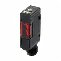


E3S-R87
Photoelectric Sensor, PNP Open Collector, 300 mm, 100 mA, 10 V to 30 V
- Manufacturer: OMRON INDUSTRIAL AUTOMATION
- Product type:
- SVHC: To Be Advised
- Product Range: E3S-R Series
- Sensing Range Max: 300mm
- Sensor Output Type: PNP Open Collector
- Supply Voltage DC Max: 30V
- Supply Voltage DC Min: 10V
| Delivery and price | |
|---|---|
| Units per pack | 1 |
| Price | 341.21 € |
| Current stock | 10+ |
| Lead time | 30 days |
Sensing Supply Voltage Output ~~es~~ > K 12 to 24 VDC 80 mA, 24 VDC with 1.5 to 4 mA constant 30 cm, 1 m current source; 100 mA, 24 VDC

## Transparent Object Detection Sensor

## **E3S-R**

## Transparent Object Sensor with Built-in DC Amplifier

Detects clear glass or plastic bottles, and transparent films with simple setup Fast, 1 ms maximum response time Choose PNP or NPN output models

Light-on/dark-on operation, wire selectable

Vertical and horizontal mounting styles

Ready-to-use: prewired with 2 m (6.56 ft) cable, includes mounting bracket

## Ordering Information

## **PLASTIC-HOUSING COMPACT MODELS**

|Connection|Appearance|Sensing<br>method|Sensing<br>distance|Light<br>source<br>color|Operating<br>modes|**Part Number**|**Part Number**|Recommended application<br>(see note 1)|Recommended application<br>(see note 1)|
|---|---|---|---|---|---|---|---|---|---|
|||||||||Flat object|Cylindrical<br>object|
|||||||NPN|PNP|Sensing of<br>glass wafers<br>and LCD glass<br>circuit boards|Sensing of<br>plastic bottles<br>and other<br>transparent<br>bottles|
|Pre-wired|Horizontal|Retrore-<br>flective|10 to<br>30 cm|Infrared|Light-ON<br>Dark-ON<br>(selectable)|**E3S-R12**|**E3S-R32**|Ideal|Ideal|
||||0.1 to 1 m|Red||**E3S-R11**|**E3S-R31**|Ideal|---|
||Vertical||10 to<br>30 cm|Infrared||**E3S-R62**|**E3S-R82**|Ideal|Ideal|
||||0.1 to 1 m|Red||**E3S-R61**|**E3S-R81**|Ideal|---|
|Plug-in<br>connector<br>**(**<br>**)**<br>see note 2|Horizontal|Retrore-<br>flective|10 to<br>30 cm|Infrared|Light-ON<br>Dark-ON<br>**(**<br>**)**<br>selectable|**E3S-R17**|**E3S-R37**|Ideal|Ideal|
||||0.1 to 1 m|Red||**E3S-R16**|**E3S-R36**|Ideal|---|
||Vertical||10 to<br>30 cm|Infrared||**E3S-R67**|**E3S-R87**|Ideal|Ideal|
||||0.1 to 1 m|Red||**E3S-R66**|**E3S-R86**|Ideal|---|


- Note: 1. The E3S-R may not easily sense some glass wafers (due to their materials) or plastic bottles (due to their shapes). Before using the E3S-R for the sensing of glass wafers or plastic bottles, be sure to use test examples of the glass wafers or plastic bottles to check if the E3S-R senses the examples easily.

   2. Refer to connector information provided later in this data sheet.

   3. Consult your OMRON representative before using the product under conditions not described in the manual or applying the product to nuclear control systems, and other systems, machines, and equipment that may have a serious influence on lives and property. Make sure that the ratings and performance characteristics of the product are correct for the systems, machines, and equipment and provide double safety mechanisms.

~~**E**~~ **3S-R**

**E3S-** ~~**R**~~

## **METAL-HOUSING MODELS**

|**METAL-HOUSING MODELS**|**METAL-HOUSING MODELS**|||||
|---|---|---|---|---|---|
|Method of detection||Retroreflective||||
|Sensingdistance||30 cm (11.81 in)||1 m (3.28 ft)||
|Mounting style||Horizontal|Vertical|Horizontal|Vertical|
|**Part Number**|**NPN Output**|**E3S-RS30E4-30**|**E3S-RS30E42-30**|**E3S-R1E4**|**E3S-R1E42**|
||**PNP Output**|**E3S-RS30B4-30**|**E3S-RS30B42-30**|**E3S-R1B4**|**E3S-R1B42**|


## Application Examples

## **TYPICAL APPLICATIONS**

## **Sensing of Glass Wafers and LCD Glass Circuit Bottles**

**==> picture [90 x 6] intentionally omitted <==**

**----- Start of picture text -----**<br>
Reflector Glass wafers<br>**----- End of picture text -----**<br>


## **Sensing of Plastic Bottles and Other Transparent Bottles**

**==> picture [112 x 21] intentionally omitted <==**

**----- Start of picture text -----**<br>
Plastic bottles<br>Reflector<br>**----- End of picture text -----**<br>


**Detecting Clear Glass Bottles on a Conveyor**

**Detecting Clear Plastic Film**

~~**E3S-R**~~

~~**E3S-R**~~

## Specifications

|Part Number||E3S-R12/-R62/-R17/<br>-R67/-R32/-R82/-R37/<br>-R87|E3S-R11/-R61/-R16/<br>-R66/-R31/-R81/-R36/<br>-R86|E3S-RS30�4/<br>-RS30�42|E3S-R1�4/-R1�42|
|---|---|---|---|---|---|
|LED for emitter||Infrared LED|Red LED|Infrared LED||
|Indicator||Light indicator (red), excess gain indicator<br>(green)||Light indicator (red)|Light indicator (red),<br>stability indicator<br>(green)|
|Sensitivity adjustment||Two-turn adjustor with an indicator||One-turn adjustor||
|Connection method||See note||Pre-wired||
|M**a**t**e**ri**a**l**s**|Case<br>Lens|Polybutylene terephthalate||Zinc die-cast||
|||Denaturedpolyallylate||Polycarbonate||


Note: The E3S-R11/-R12/-R61/-R62/-R31/-R32/-R81/-R82 each have a pre-wired cord. The E3S-R16/-R17/-R66/-R67/-R36/-R37/-R86/-R87 each have a plug-in connector.

## � **RATINGS/CHARACTERISTICS**

|Item|Item|E3S-R12/-R62/<br>-R17/-R67|E3S-R11/-R61/<br>-R16/-R66|E3S-R32/-R82/<br>-R37/-R87|E3S-R31/-R81/<br>-R36/-R86|E3S-RS30�4/<br>-RS30�42|E3S-R1�4/<br>-R1�42|
|---|---|---|---|---|---|---|---|
|Power supply voltage||10 to 30 VDC; ripple: 10% max.||||12 to 24 VDC±10%; ripple: 10%<br>max.||
|Current consumption||30 mA max.||||40 mA max.||
|Sensingdistance||10 to 30 cm|0.1 to 1 m|10 to 30 cm|0.1 to 1 m|30 cm|1 m|
|Sensing method||Retroreflective|Retroreflective<br>with polarized<br>function|Retroreflective|Retroreflective<br>with polarized<br>function|Retroreflective||
|Standard sensing<br>object||0.7-mm-thick LCD<br>glass boards;<br>10-mm-dia.,<br>1.0-mm-thick,<br>30-mm-long cylindri-<br>cal glass objects|0.7-mm-thick<br>LCD glass<br>boards|0.7-mm-thick<br>LCD glass<br>boards;<br>10-mm-dia.,<br>1.0-mm-thick,<br>30-mm-long cy-<br>lindrical glass<br>objects|0.7-mm-thick<br>LCD glass<br>boards|10-mm-dia., 1.0-mm-thick,<br>30-mm-long cylindrical glass<br>objects||
|Response time||1 ms max. for both operation and release||||||
|Control output (no-<br>contact output)||NPN open collector, 30 VDC, 100 mA<br>max.||PNP open collector, 30 VDC,<br>100 mA max.||Output current: 1.5 to 4 mA at<br>24 VDC;<br>NPN output (with suffix -E):<br>80 mA<br>PNP output (with suffix -B):<br>100 mA||
|Ambient<br>illumina-<br>tion|Incandes-<br>cent lamp|5,000�x max.||||Illumination on optical spot:<br>3,000�x max.||
||Sunlight|10,000�x max.||||Illumination on optical spot:<br>10,000�x max.||
|Ambient temperature||Operating: 0°C to 40°C (32°F to 104°F) with no icing|||||Operating:<br>--25°C to 55°C<br>(--13°F to<br>131°F) with no<br>icing|
|Ambient humidity||Operating: 35% to 85%||||||
|Insulation resistance||20 MΩmin. (at 500 VDC)||||||
|Dielectric strength||1,000 VAC, 50/60 Hz for 1 min||||||
|Vibration resistance||Destruction: 10 to 55 Hz, 1.5-mm double amplitude for 2 h each in X, Y, and Z directions||||||
|Shock resistance||Destruction: 500 m/s2 (approx. 50G)for 3 times each in X, Y, and Z directions||||||
|Protection||Load short-circuit protection, reverse polarity protection, mutual interfer-<br>ence prevention||||Load short-circuit protection,<br>mutual interference prevention||
|Enclosure rating||IEC:<br>IP67||||||


Note: 1. The above sensing distances are possible when the E39-R1 Reflector is used. The E39-R1 Reflector is provided with the E3S-R.

2. Even though the excess gain indicator of the E3S-R is dimly lit during sensitivity adjustment of the E3S-R, the E3S-R will provide stable operation if the ambient temperature does not rise or fall by more than 5°C while the E3S-R is operating.

~~**E**~~ **3S-R**

**E3S-** ~~**R**~~

## a **CHARACTERISTIC DATA (REFERENCE VALUES)**

## **Light Level Change Rates with Various Transparent Objects (See Note 1)**

The following are the permeation rates of a various transparent objects on condition that a permeation rate of 100 means that there is no object within the sensing distance of the E3S-R. The permeation rate of any type of object sensed by the E3S-R must be as low as possible for the stable sensing of the object. Before using the E3S-R to sense objects, use samples of the objects to check if the E3S-R can sense the samples easily.

|stable sensing of the object. Before using the E3S-R to sense objects, use samples of the objects to check if the E3S-R can sense the samples<br>easily.|stable sensing of the object. Before using the E3S-R to sense objects, use samples of the objects to check if the E3S-R can sense the samples<br>easily.|stable sensing of the object. Before using the E3S-R to sense objects, use samples of the objects to check if the E3S-R can sense the samples|stable sensing of the object. Before using the E3S-R to sense objects, use samples of the objects to check if the E3S-R can sense the samples|stable sensing of the object. Before using the E3S-R to sense objects, use samples of the objects to check if the E3S-R can sense the samples|stable sensing of the object. Before using the E3S-R to sense objects, use samples of the objects to check if the E3S-R can sense the samples|
|---|---|---|---|---|---|
|Sensing Object<br>~~i~~<br>~~ee~~||E3S-R12/-R62/-R17/<br>-R67/-R32/-R82/<br>-R37/-R87<br>~~ae~~|E3S-R11/-R61/-R16/<br>-R66/-R31/-R81/<br>-R36/-R86<br>~~eee~~|E3S-RS30<br>~~eee~~|E3S-R1<br>~~eee~~|
|||Center<br>~~ae~~<br>~~ee~~|Center<br>~~eee~~<br>~~GG~~|Center<br>~~eee~~<br>~~GG~~|Center<br>~~eee~~|
|**Cy**lin**d**ri**ca**l**g**l**ass**<br>**bj**<br>**t**<br>o ec<br>~~SSSS>~~<br>||10-dia. x 30, t = 1.0<br>~~ee~~<br>~~SSSS>~~|27<br>~~ae ~~<br>~~ee~~<br>~~SSSS>~~|---<br> ~~eee ~~<br>~~GG~~<br>~~SSSS>~~|20<br> ~~eee~~<br>~~GG~~<br>~~SSSS>~~|33<br>~~eee~~<br>~~SSSS>~~|
||15-dia. x 30, t = 1.25<br>~~ee~~<br>~~ee~~<br>~~SSSS>~~|27<br>~~ee~~<br>~~ee~~<br>~~SSSS>~~|---<br>~~GG~~<br>~~GG~~<br>~~SSSS>~~|20<br>~~GG~~<br>~~GG~~<br>~~SSSS>~~|13<br>~~SSSS>~~|
||20-dia. x 30, t = 1.7<br>~~SSSS>~~|22<br>~~SSSS>~~|---<br>~~SSSS>~~<br>~~Ge~~|28<br>~~SSSS>~~|13<br>~~SSSS>~~|
||30-dia. x 30, t = 1.9<br>~~SSSS>~~<br>~~Gs~~|41<br>~~SSSS>~~<br>~~Gs~~|---<br>~~SSSS>~~<br>~~Gs~~<br>~~Ge~~|43<br>~~SSSS>~~<br>~~Gs~~|23<br>~~SSSS>~~<br>~~Gs~~|
||100-dia. x 30, t = 2.5<br>~~SSSS>~~<br>~~eG~~<br>~~a~~|58<br>~~SSSS>~~<br>~~eG~~|---<br>~~SSSS>~~<br>~~Ge~~<br>~~eG~~<br>~~Ge~~|55<br>~~SSSS>~~<br>~~eG~~|50<br>~~SSSS>~~<br>~~eG~~|
||200-dia. x 30, t = 5.0<br>~~SSSS>~~<br>~~Ge~~<br>~~a~~|55<br>~~SSSS>~~<br>~~Ge~~<br>~~Ge~~|---<br>~~SSSS>~~<br>~~Ge~~<br>~~Ge~~<br>~~Ge~~|58<br>~~SSSS>~~<br>~~Ge~~|58<br>~~SSSS>~~<br>~~Ge~~|
|Glass plate<br>||50 x 50, t = 0.5<br>~~a~~|82<br>~~Ge~~|91.5<br>~~Ge~~<br>~~Ge~~|78|---|
||50 x 50, t = 1<br>~~Se~~<br>~~a~~|74<br>~~Ge~~<br>~~Se~~<br>~~Gn~~|82.5<br>~~Ge~~<br>~~Se~~<br>~~Ge~~|70|75|
||50 x 50, t = 2<br>~~a~~<br>~~re~~|73<br>~~Ge~~<br>~~Gn~~|81<br>~~Ge~~<br>~~Ge~~|70|75|
||50 x 50, t = 3<br>~~a~~<br>~~re~~<br>~~ee~~|62<br>~~Ge~~<br>~~Gn~~|69<br>~~Ge~~<br>~~Ge~~|58|65|
||50 x 50, t = 5<br>~~re~~<br>~~ee~~|53<br>~~Ge~~|59<br>~~Ge~~|50|55|
||50 x 50, t = 10<br>~~ee~~|38<br>~~Ge ~~|42<br> ~~Ge~~|35|40|
|Liquid crystal<br>glass|t = 0.5 (permeability<br>of 98%) (see note 2)|86|96|---|---|
||t = 0.7 (permeability<br>of 95%) (see note 2)|81|90|---|---|
||t = 1.1 (permeability<br>of 91%) (see note 2)|75|83<br>~~GO~~|---<br>~~GO~~|---|
|Operating range<br>~~Qe~~||95 max.<br>~~Qe~~|95 max.<br>~~Qe~~<br>~~GO~~|90 max.<br>~~Qe~~<br>~~GO~~|80 max.<br>~~Qe~~|
|Stable operatingrange<br>~~QQ~~||90 max.<br>~~QQ~~|90 max.<br>~~GO~~<br>~~QQ~~|70 max.<br>~~GO~~<br>~~QQ~~|60 max.<br>~~QQ~~|


Note: 1. The sensing distance of each model was set to the rated sensing distance.

2. The permeability values were checked with light with a wavelength of 700 µm.

## Engineering Data

**REFLECTOR OPERATING RANGE (TYPICAL)**

**E3S-R11/-R61/-R16/-R66/-R31/-R81/ -R36/-R86**

**E3S-R12/-R62/-R17/-R67/-R32/-R82/ -R37/-R87**

**==> picture [398 x 77] intentionally omitted <==**

**----- Start of picture text -----**<br>
Cs ree<br>ft {Laat<br>Distance (cm)<br>No o at aol Distance (cm)<br>a Pe e<br>(mm)<br>(mm)<br>Distance Y distance<br>**----- End of picture text -----**<br>


~~9~~ ~~**E3S-R** AROIITYNHH———____~~ ~~**E3S-R**~~

## **EXCESS GAIN VS. SET DISTANCE (TYPICAL)**

**E3S-R11/-R61/-R16/-R66/-R31/-R81/-R36/-R86 with E39-R1**

**==> picture [137 x 116] intentionally omitted <==**

**----- Start of picture text -----**<br>
Operating level<br>Operating level distance (mm)<br>Excess gain ratio<br>**----- End of picture text -----**<br>


## **E3S-R12/-R62/-R17/-R67/-R32/-R82/ -R37/-R87**

**==> picture [114 x 113] intentionally omitted <==**

**----- Start of picture text -----**<br>
Operating level<br>Distance (mm)<br>Excess gain ratio<br>**----- End of picture text -----**<br>


## Operation

## **OUTPUT CIRCUITS**

## **E3S-R11/-R12/-R61/-R62/-R16/-R17/-R66/-R67**

**==> picture [218 x 70] intentionally omitted <==**

**----- Start of picture text -----**<br>
Brown<br>Light Stability<br>indicator indicator<br>Load<br>(Red) (Green) (relay)<br>100 mA max. Black 10 to<br>Main 30 VDC<br>circuit<br>thot<br>Blue<br>**----- End of picture text -----**<br>


## **E3S-R31/-R32/-R81/-R82/-R36/-R37/-R86/-R87**

**==> picture [198 x 71] intentionally omitted <==**

**----- Start of picture text -----**<br>
10 to<br>Lightindica- Stabilityindicator Brown 30 VDC<br>tor ZD<br>Black Control output<br>Main<br>(Red) (Green) circuit<br>Load<br>Blue<br>0 V<br>**----- End of picture text -----**<br>


~~**E**~~ **3S-R**

**E3S-** ~~**R**~~

> **E3S-RS30** ~~O~~ **4/-RS30** ~~O~~ **42/-R1** ~~O~~ **4/-R1** ~~O~~ **42**

**==> picture [464 x 116] intentionally omitted <==**

**----- Start of picture text -----**<br>
Color of Code Polarity of Output Output Circuit<br>a Power Supply Configuration<br>Brown + Light-ON Brown 12 to<br>(see note 1) Stability indi- (see note 1) 24 VDC<br>Light cator (see<br>Blue 0 V indicator note 2) Load 1<br>| (see note 1) (Red) (Green) M a n i 1.54 m toA c Black (relay) 80 mA max.<br>Brown 0 V Dark-ON circuit<br>(see note 1) Load 2 (See note 3)<br>Blue 1.5 to 4 mA<br>Blue +<br>0 V<br>(see note 1) (see note 1)<br>**----- End of picture text -----**<br>


- Note: 1. Reverse the polarity of the power supply to change the output mode.

   2. The E3S-RS30 O and E3S-RS30 O 42 do not have a stability indicator. 3. This load is needed when voltage output to connect a transistor circuit is required.

**==> picture [487 x 432] intentionally omitted <==**

**----- Start of picture text -----**<br>
|||||||||
|---|---|---|---|---|---|---|---|
|a|TIMING CHARTS|
|E3S-R11/-R12/-R61/-R62/-R16/-R17/-R66/-R67/-R31/-R32/-R81/-R82/-R36/-R37/-R86/-R87|
|GO|Output Transistor|Timing Charts|
|ON when light is received|Light receivedLight not received|_|
|Light indicator(red)|OFFON|_|
|Output|ON|
|transistor|OFF|
|Load|Operate|(Between brown and black)|
|(relay)|Release|
|et|ON when light is not received|Light received|
|Light not received|
|Light indicator|ON|
|(Orange)|OFF|
|Output|ON|
|transistor|OFF|-|
|Load(relay)|ReleaseOperate|||(Between brown and black)|
|PL|a|Ee|
|E3S-RS30|C|4/-RS30|L|42/-R1E|O|/-R1|42|
|Color of Code|Polarity of|Output|Timing Charts|
|a|Brown|Power Supply+|aee|TransistorON when light|e|
|Light received|
|(see note)|is received.|Light not received|
|Light indicator(red)|OFFON|=|
|a|Output|transistor|OFF|ON|SsSs|
|Blue (see note)|0 V|
|Load|Operate|(Between brown and black)|
|(relay)|Release|
|Output voltage|H|
|(logic, etc.)|L|=|(Between blue and black)|
|Brown|0 V|ON when light|
|||[|]|Light received|SS|
|(see note)|is not received.|Light not received|
|Light indicator(red)|OFFON|on|
|Output|ON|
|transistor|OFF|a|
|Blue (see note)|+|
|Load|Operate|(Between blue and black)|
|(relay)|Release|a|
|Output voltage|H|
|||(logic, etc.)|L|=||(Between brown and black)|
|Note:|Reverse the polarity of the power supply to change the output mode of the E3S-R.|[|e|

**----- End of picture text -----**<br>


~~9~~ ~~**E3S-R** AROIITYNHH———____~~ ~~**E3S-R**~~

## Dimensions

Unit: mm (inch)

**==> picture [456 x 231] intentionally omitted <==**

**----- Start of picture text -----**<br>
E3S-R11/-R12/-R31/-R32 Light indicator (red) Sensitivity adjustor (white)4<br>A —-<br>B 7 Polyvinyl chloride-covered cord<br>(4-mm dia., 0.12-mm x 18, 3 cores)<br>(0.28) Standard length: 2 m<br>12.4 12 (0.47)<br>(0.49)<br>16.9<br>16.5 (0.67) (0.42)10.7<br>(0.65) 3.2 7.2 (0.28)<br>3.2 Stainless steel (SUS304)<br>Stability indicator(green) 10.5 Aeaaee 5 4.8(0.79)20 7.2 Two mounting holes<br>Lens (7 x 14) ReceiverOptical axis (0.41) (1.18)30 Mode selector (black)Dark-ON Light-ON<br>29.2 1 .3<br>21 Mounting Holes<br>(1.15)<br>(0.83)<br>Two, M3<br>11.5 9<br>(0.45) 19.7<br>(0.78) 20<br>Emitter 10.7 (0.79)<br>The mounting bracket canbe attached to this side. mh 1.2 o @ Two, M3 x 12  y ( of —9<br>**----- End of picture text -----**<br>


## **E3S-R11/-R12/-R31/-R32**

|T**y**pe|NPN output|E3S-R11|E3S-R12|
|---|---|---|---|
||PNP output|E3S-R31|E3S-R32|
|Size|A|42.3(1.67)|40(1.57)|
||B|15.2(0.60)|12.9(0.51)|


## **E3S-R61/-R62/-R81/-R82**

**==> picture [478 x 300] intentionally omitted <==**

**----- Start of picture text -----**<br>
E3S-R61/-R62/-R81/-R82 Receiver Optical axis<br>Lens (7 x 14) (1.57)40 Emitter 4<br>17 4.8 Polyvinyl chloride-covered cord(4-mm dia., 0.12-mm x 18, 3 cores)<br>Standard length: 2 m<br>12.4 12 (0.47)<br>(0.49)<br>16.9 Use these two<br>16.5 (0.67)1 0.7 holes for mounting.<br>(0.65) (0.42)<br>7.2<br>| | 5.5 ea 5.4 3.1 (0.79)20 Four mountingholes<br>Stability indicator Light indicator (red) 3.6 41.7 7.2 Mode selector (black)<br>(green) Sensitivity adjustor(white) (1.64) Dark-ON Light-ON<br>B<br>7<br>A<br>C Mounting Holes<br>Two, M3<br>man: 1.2 [10.7] | LG oH fl S|<br>(0.42)<br>The mounting bracket canbe attached to this side. ta ) 1.3 (0.41)10.5 H (0.7920±± ER 0.20.01) Two, M3 x 12 Pe, (0.79)20<br>T y p e NPN output E3S-R61 E3S-R62<br>PNP output E3S-R81 E3S-R82<br>Size A 23.3 (0.92) 21 (0.83)<br>B 5.9 (0.23) 3.6 (0.14)<br>C 31.5 (1.24) 29.2 (1.15)<br>**----- End of picture text -----**<br>


~~a~~ ~~**E**~~ **3S-R**

**E3S-** ~~**R**~~

**==> picture [115 x 9] intentionally omitted <==**

**----- Start of picture text -----**<br>
E3S-R16/-R17/-R36/-R37<br>**----- End of picture text -----**<br>


**==> picture [444 x 603] intentionally omitted <==**

**----- Start of picture text -----**<br>
Light indicator (red) Sensitivity adjustor (white)<br>\ A 10 M12 Connector<br>B 7 (0.39)<br>(0.28)<br>12<br>1 2.4 (0.47) Mounting Holes<br>(0. 49)<br>Two, M3<br>16.9<br>16.5 (0.67) 10.7<br>eS (0.65) e= (0.42) S 3.2 7.2 (0.28) <—— (0.79)20<br>Stability indicator (green) /| ta 5 3.24.8 Two mounting holes \<br>20 (0.79) 7.2<br>Receiver 10.5 SS 30 (1.18) Mode selector (black)<br>Lens (7 x 14) Optical axis (0.41) Dark-ON Light-ON<br>21 1.3<br>(0.83)<br>11.5 9 29.2<br>(0.45) (1.15)<br>r 19.7 ‘ Eh<br>Emitter 10. 7 (0.78)<br>The mounting bracket can<br>be attached to this side. 1.2 Two, M3 x 12<br>(0.05)<br>T y pe NPN output E3S-R16 E3S-R17<br>PNP output E3S-R36 E3S-R37<br>Size A 42.3 (1.67) 40 (1.57)<br>B 15.2 (0.60) 12.9 (0.51)<br>a E3S-R66/-R67/-R86/-R87<br>Receiver Optical axis<br>Lens (7 x 14) Emitter M12 Connector<br>40 (1.57) 10<br>17 (0.39)<br>a|i 14.9 (0.59) VP 12 FONT pS<br>(0.47)<br>19.4<br>(0.76) Use these two<br>10 .7 holes for mounting.<br>16.5 (0.42) 7.2<br>(0.65)<br>20<br>3.1 (0.79) 7.2 Four mountingholes<br>3.6<br>a Stability indicator (green) Light indicator (red) pu os 41.7 (1.64) Mode selector (black)<br>Sensitivity adjustor (white) Dark-ON Light-ON<br>B<br>7<br>A<br>C<br>| Lrs i—_ -_<br>1.2 [10.7]<br>The mounting bracket can (0.42)<br>be attached to this side.<br>1.3 10.5 20±0.2<br>E39-L60 Close Mounting Plate(attachment) (0.41) (0.79±0.01) Two, M3 x 12 Mounting Holes<br>(Attach the mounting plate or the<br>plug cannot be connected.) Two, M3<br>&7 20<br>(0.79)<br>**----- End of picture text -----**<br>


|T**y**pe|NPN output|E3S-R66|E3S-R67|
|---|---|---|---|
||PNP output|E3S-R86|E3S-R87|
|Size|A|23.3(0.92)|21(0.83)|
||B|5.9(0.23)|3.6(0.14)|
||C|31.5(1.24)|29.2(1.15)|


~~O~~ ~~**E3S-R** IRO~~ ~~**E3S-R**~~ 7 **E3S-RS30** Oo **4/-R1** 6 **4**

**==> picture [478 x 526] intentionally omitted <==**

**----- Start of picture text -----**<br>
Cord: Vinyl-insulated cord (4-mm dia.,<br>0.12-mm x 18, 3 cores) Indicator Sensitivity adjustor<br>Weight: Approx. 165 gStandard length: 2 m Z The mounting bracket canbe attached to this side. (0.91)2023 7.1 Lens (10 x 15) 55 (2.17)66.6 (2.62)11 13 J 7<br>20.4 20<br>(0.80) (0.79) 13 dia.<br>22.2<br>(0.87)<br>20<br>(0.79) 5 4.2<br>Be: Emitter Wop<br>Receiver<br>1.6 2.1R 2.1R<br>12 4.2 5<br>2224.9 Two, M4 slotted hexagonhead bolts ti 6.5 25.439 1.9<br>32 (1.54) (0.07)<br>(1.26)<br>Mounting Holes Note: The E3S-RS30 O 4 does not have a green stability<br>indicator.<br>Two, M4<br>Loo 25.4<br>(1.00)<br>7 E3S-RS30 o 42/-R1 66d 42 _ 21.5 =<br>(0.85)<br>18.6<br>Cord: Vinyl-insulated cord (4-mm dia.,<br>0.12-mm x 18, 3 cores) Lens (10 x 15)<br>Standard length: 2 m $<<br>Weight: Approx. 165 g<br>7.1 Receiver<br>Emitter<br>Indicator Sensitivity adjustor<br>74.6 (2.94)<br>The mounting bracket canbe attached to this side. (0.91)23 63 7<br>20 11 13<br>A EH<br>20.4 20<br>(0.80)10.2 (0.79) 13 dia.<br>22.2<br>(0.87)<br>- (0.79)20 5 4.2<br>| fone<br>1.6 2.1R<br>2.1R<br>12 4.2 5<br>32 Two, M4 slotted hexagon nl 25.4<br>: (1.26) head bolts il 6.5 39 i 1.9<br>(1.54) (0.07)<br>Mounting Holes<br>Note: The E3S-RS30 Oo 42 does not have a green stability<br>Two, M4 indicator.<br>,<br>7 \i<br>25.4<br>Lot<br>(1.00)<br>**----- End of picture text -----**<br>


~~OO~~ ~~**E**~~ **3S-R** ~~ORO~~ **E3S-** ~~**R**~~ a **ACCESSORIES**

## **E39-R1 Retroreflector (Attachment)**

**==> picture [201 x 146] intentionally omitted <==**

**----- Start of picture text -----**<br>
40.3<br>(1.59)<br>34<br>Two, 3.5 (0.14) dia (0.28)7 (1.34) (0.30)7.5<br>52<br>59.9 (2 .05)<br>(2.36)<br>1.6<br>8 (0.31)<br>ae 2.7<br>(0.11)<br>**----- End of picture text -----**<br>


**E39-G1 Sensitivity Adjustor Knob for the E3S-RS30 and E3S-R1** OOO **/-R1B** OO **(Attachment)**

**==> picture [127 x 73] intentionally omitted <==**

**----- Start of picture text -----**<br>
Le<br>Sy<br>9.3 dia.<br>13 dia.<br>age :<br>**----- End of picture text -----**<br>


## **E39-G2 Sensitivity Adjustor Knob for E3S-R**

**==> picture [68 x 80] intentionally omitted <==**

**----- Start of picture text -----**<br>
8 (0.31) dia.<br>1<br>0.80 (0.04)<br>12.6<br>(0.50)<br>Polycarbonate<br>7 (0.28) dia.<br>**----- End of picture text -----**<br>


## **Connecting Method of the Sensitivity Adjustor Knob**

Press the sensitivity adjusting knob so that the pointer of the sensitivity adjusting knob is in the direction shown in the illustration to connect the sensitivity adjusting knob to the E3S-R.

Make sure to connect the sensitivity adjusting knob correctly. It is impossible to remove the sensitivity adjusting knob from the E3S-R after it is connected to the E3S-R.

~~**E3S-R**~~

~~**E3S-R**~~

**E39-L2 Special Mounting Bracket for the E3S-RS30 and E3S-R1(Order Separately)**

**==> picture [387 x 142] intentionally omitted <==**

**----- Start of picture text -----**<br>
92.1<br>(3.63)<br>82.1 (3.23)<br>Mounting Holes<br>10.2<br>(0.40) 20.2<br>| Lee] _<br>(0.80) Two, M4 25.4<br>(1.00)<br>41<br>(1.61) 25.4 5<br>(1.00) 4.2<br>4.2<br>Two, M4 slotted<br>Lt 5.6 UHR 2.1 R 5 a hexagon head bolts ’ (1.00)25.4 9 _ (1.15)29.1 =i<br>(0.22)<br>**----- End of picture text -----**<br>


**E39-L69 Mounting Bracket for E3S-R Horizontal Type (Attachment)**

**E39-L70 Mounting Bracket for E3S-R Vertical Type (Attachment)**

**==> picture [431 x 152] intentionally omitted <==**

**----- Start of picture text -----**<br>
16.3 20±0.2<br>3.2 Stainless steel (0.64)20±0.2(0.79±0.01)16.3<br>20±0.2 (SUS403) teh<br>5 (0.79±0.01) 3.1<br>Stainless steel 10.716.5<br>(SUS403) 4 3.1 [10.7] 16.5 7.2 (0.28) | (0.65)<br>7.2 (0.28) (0.65) BE aR<br>3.1 7.2 7.2<br>1.2 3.1 (0.12) 7.2 (0.28) (0.12) (0.28) 3.1 2.05 (0.28)<br>(0.05) 3.2 (0.13)<br>3.1 (0.12) 7.2 (0.28) 1.2<br>(0.05) 2.05 (0.08) 31.7±0.1 2.05 (0.08)<br>(0.28)7.2 16.5 €s> 3.1 (0.12) H 11.4 3.1<br>3.1 10.7(0.65) 7.2 (0.28) 7.216.5<br>5<br>(0.20) 20±0.2 10.7 (0.42) (0.65)<br>Lar 30 (1.18) “Lgia<br>a 41.7 (1.64) | ay,——.|<br>**----- End of picture text -----**<br>


**==> picture [378 x 117] intentionally omitted <==**

**----- Start of picture text -----**<br>
E39-L60 Contact Mounting Plate for E3S-R<br>Plug-in Connector Type (Order Separately)<br>6.5 33 (1.30)20 (0.79) 6.5 (0.46)11.75 (0.10)2.5<br>(0.26) (0.26)<br>11.75<br>| (0.46) — 4 a 3.4 dia.<br>5 2.5<br>& fo 3.4 dia. Lp<br>Polybutyleneterephthalate (0.20)5 |<br>**----- End of picture text -----**<br>


~~**E**~~ **3S-R**

**E3S-** ~~**R**~~

## **ACCESSORIES (ORDER SEPARATELY)**

**E39-L59 Vertical Mounting Bracket for E3S-R** |

**==> picture [353 x 203] intentionally omitted <==**

**----- Start of picture text -----**<br>
20<br>(0.79)<br>In . _ - OD 3.1<br>18 (0.12)<br>(0.71) 11<br>(0.43)<br>li nea<br>3.1 3.1<br>(0.12)<br>Sain 7.2<br>(0.28)<br>3.2<br>20<br>34.5 (0.79)<br>(1.36)<br>_ 2<br>7.2 (0.08)<br>9.5 | iil<br>(0.37) HEESiF, 3.2<br>3.2 10.5 63.8 (2.51)<br>9.4 74.3 (2.93)<br>(0.37)<br>**----- End of picture text -----**<br>


## Installation

## **CONNECTIONS**

If the brown and blue lead wires are connected in reverse, the output mode can be changed for the E3S-RS30E || and E3S-R1E || /-R1B OHO (Light-ON, Dark-ON). Blue 0V 12 to 24 V Brown 80 mA max. Black Load Output ~~a~~

## **With S3D2 Sensor Controller**

The E3S-R will operate in reverse using the signal input selector of the S3D2.

**==> picture [107 x 144] intentionally omitted <==**

**----- Start of picture text -----**<br>
Brown<br>Black<br>Blue<br>IN<br>+12 V 1 0 V<br>Ir | a ||<br>S3D2<br>**----- End of picture text -----**<br>


## **PLUG (FOR E3S-R WITH CONNECTOR)**

## **Internal Connection**

|@|Terminal No.<br>Brown<br>(No connection)<br>Blue<br>Black<br>1<br>2<br>3<br>4<br>SSS5|Terminal No.<br>Brown<br>(No connection)<br>Blue<br>Black<br>1<br>2<br>3<br>4<br>SSS5|Terminal No.<br>Brown<br>(No connection)<br>Blue<br>Black<br>1<br>2<br>3<br>4<br>SSS5|Terminal No.<br>Brown<br>(No connection)<br>Blue<br>Black<br>1<br>2<br>3<br>4<br>SSS5|
|---|---|---|---|---|
|Item||Color of|Conection|Application|
|||Cord|Pin No.||
|For DC||Brown|1|Power supply (+V)|
|||Black|4|Output|
|||Blue|3|Power supply (0 V)|
|||---|2|No connection|


~~_~~ ~~**E3S-R** -~~

~~———_-~~ ~~**E3S-R** _~~

## Precautions

- **DEFINITIONS OF PRECAUTIONARY INFORMATION**

- ~~A~~ ~~**!**~~ **DANGER!** Indicates an imminently hazardous situation which, if not avoided, will result in death or serious injury. Limited tomost extremesituations.

## **DEFINITIONS OF PRECAUTIONARY INFORMATION**

- ~~LN~~ ~~**!**~~ **WARNING** Indicates a potentially hazardous situation which, if not avoided, could result in death or serious injury.

- ~~LS~~ ~~**!**~~ **Caution** Indicates a potentially hazardous situation which, if not avoided, may result in minor or moderate injury. May also be used to alert against unsafe practices and property damage-only accidents.

## **WARNING** ~~L\~~ ~~**!**~~

> Item ~~a~~ Examples **Power supply** Brown Do not impose an excessive voltage on the E3S-R, otherwise it ~~Load~~ may explode or burn. Do not impose 100 VAC on any E3S-R DC Sensor model, otherwise it may explode or burn. Black Blue ~~a~~ **Load short-circuit** Brown Do not short-circuit the load, or the E3S-R may explode or burn. Load The E3S-R’s short-circuit protection function is valid if the polarity Sensor of the supply voltage imposed is correct and within the rated Black voltage range. Blue

**==> picture [156 x 275] intentionally omitted <==**

**----- Start of picture text -----**<br>
Brown<br>Load<br>Sensor Incorrect<br>Black<br>Blue<br>Brown<br>Load<br>Sensor Incorrect<br>Black<br>Blue<br>Load<br>Brown<br>Sensor Incorrect<br>Black<br>Blue<br>Brown<br>12 to 24 VDC<br>Load Incorrect<br>Sensor<br>Black<br>0 V<br>Blue<br>**----- End of picture text -----**<br>


## **Wiring**

Be sure to wire the E3S-R and load correctly, otherwise it may explode or burn.

## **Connection with no load**

Make sure to connect a proper load to the E3S-R in operation, otherwise it may explode or burn.

~~**E**~~ **3S-R** ~~———~~

**E3S-** ~~**R**~~

## **ADJUSTMENT**

When the E3S-R senses a cylindri cal obje ct, the amoun t of ligh t received varies wit h the dire ctio n of the cylindri cal obje ct. To prevent this , locat e the E3S-R as show n in the followin g illustration.

## **WIRING**

## **Cord**

Thecord can be extende d up to 100 m pro vided that the thi ckness of the cord is 0.3 mm[2] maximum.

## **RepeatedBending**

The cable must not be bent repeatedl y.

## **High-tensionLines**

When theE3S-Rsenses an uneven plastic containe r or glass bottle, the amoun t of ligh t received varies wit h the dire ctio n and sensing part of the plastic containe r or glass bottle . To prevent thi s, tur n a sampl e of the plastic containe r or glass bottl e to the best sensing positio n of the E3S-R to fin d and decide the optimu m dire ctio n and sensing part , and then make the sensiti vity adju stment.

In prin ciple , sensing obje cts must pass throug h the center between the E3S-R and the refle ctor. Sensing obje cts must not be too close to the refle ctor, otherwi se sensing error s may result.

## **INSTALLATION**

## **Power Reset Time**

The Photoele ctri c Sensor is ready to operat e withi n 100 ms after powe r is supplied . If powe r supplie s are conne cted to the Photoelectri c Sensor and load respectively, be sure to suppl y powe r to the Photoele ctri c Sensor befor e suppl ying powe r to the load.

The powe r suppl y line s of the Photoele ctri c Sensor must not be wire d along side powe r line s or high-ten sion line s in the same conduit , otherwi se the Photoele ctri c Sensor may become damage d or malfun ctio n due to indu ctio n noi se that may be generate d fro m the powe r line s or high-ten sion line s.

## **CordTractive Force**

Do not pul l cord s with the tractive forces exceedin g the following.

|Diameter|Tractive Force|
|---|---|
|4 dia. max.|30 N max.|
|4 dia. min.|50 N max.|


Note: Do not impo se tensilestress on any shielde d wir e or coaxial cable.

## **UnusedLead Wired**

Cut any unu sed lead wir e of the Photoele ctri c Sensor, such as a lead wir e for self-diagno stic output , and insulat e the lead wir e with insulatin g tapeso that the wir e wil l not tou ch any termina l of the Photoele ctri c Sensor.

## **Power OFF**

The Photoele ctri c Sensor may outpu t a pul se signa l when it is turne d off . Therefore , it is recommende d to tur n off the load before turnin g off the Photoele ctri c Sensor.

## **Types of PowerSupplies**

The Photoele ctri c Sensor must not be conne cted to a nonsmoothed , all-wa ve or half-wa ve rectifie d powe r suppl y.

**Omron Europe B.V. EMA-ISD, tel:+31 23 5681390, fax:+31 23 5681397, http://www.eu.omron.com/ema**

~~CT~~ **NOTE: DIMENSIONS SHOWN ARE IN MILLIMETERS. To convertmillimetersto inchesdivideby 25.4.**

Cat. No. CEDSAX2

Specification s subjec t to chang e withou t notice.

Printe d in U.S.A.

3/97
Updated at April 23, 2026
With a legacy spanning over 80 years, Omron Industrial Automation is a globally recognized leader in the manufacture of advanced industrial control and automation components. Renowned for their reliability and engineering excellence, Omron delivers comprehensive solutions that enhance efficiency, machine safety, and precision across a wide range of manufacturing environments. Our extensive portfolio of Omron products is heavily focused on their industry-leading sensing and switching technologies. We offer a vast selection of sensors, excelling specifically in high-performance proximity sensors, light sensors, and temperature sensors. Complementing this range are robust switching solutions, featuring a deep inventory of power relays, solid-state relays, safety relays, and essential relay accessories designed for demanding operational requirements. Beyond sensing and switching, Omron is highly regarded for its precision automation and process control equipment. Our selection features highly accurate temperature controllers, versatile process controllers, and sophisticated panel displays and instrumentation. To support these fundamental systems, we also supply dependable Omron power supplies, notably AC/DC converters, alongside vital connectivity components like DIN rail terminal blocks to ensure secure, efficient, and complete industrial setups.
About Novapart
Novapart is a B2B electronic component broker specialising in stock shortages and cost reduction. We source hard-to-find parts and identify compliant alternatives across a catalogue of 410,000+ components from 500+ manufacturers.
Learn more →Stock Shortage Specialist
When a component is unavailable, discontinued or has an unacceptable lead time, we tap into our network of vetted European and Asian distributors to source what you need — without compromising on quality or traceability.
Request a quote →Compliant Alternatives
We identify pin-to-pin, electrically equivalent substitutes that meet the same certifications (RoHS, AEC-Q100, REACH) as your original specification — validated against datasheets, not just part numbers. Often at a lower cost.
BOM Analysis service →