
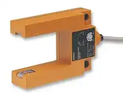


E3S-GS3B4
Photoelectric Sensor, E3S-GS Series, Mark, Through Beam, 30 mm, PNP, Fork, Grooved, 12 Vdc to 24Vdc
- Manufacturer: OMRON INDUSTRIAL AUTOMATION
- Product type:
- Sensor Output:PNP; Sensing Range Max:30mm; Supply Voltage DC Min:12V; Supply Voltage DC Max:24V; Output Current:100mA; Product Range:E3S-GS Series; Current Consumption:40mA; External D
- IP Rating: IP67
- Output Type: PNP Open Collector
- Sensor Type: Photoelectric Sensors
- Light Source: Infrared LED
- Product Range: E3S Series
- Qualification: -
- Sensing Method: Grooved-Type
- Connection Method: Cable
- Sensing Range Max: 30mm
- Sensor Output Type: PNP
- Supply Voltage Max: 24VDC
- Supply Voltage Min: 12VDC
- Sensing Distance Max: 30mm
- Supply Voltage DC Max: 24V
- Supply Voltage DC Min: 12V
- Operating Temperature Max: 55°C
- Operating Temperature Min: -25°C
| Delivery and price | |
|---|---|
| Units per pack | 50 |
| Price | 248.67 € |
| Current stock | 10+ |
| Lead time | 30 days |
**Photoelectric Sensor with Built-in Amplifier E3S**

CSM_E3S_DS_E_12_1

## **General-purpose Photoelectric Sensor for High Quality and Reliable Detection**

|**General-purpose Photoelectric**<br>**Sensor for High Quality and Reliable**<br>**Detection**<br>Be sure to read_Safety Precautions_<br>on page 8.<br>Note: E3S-2/-5/-DS10/-DS30/-R2 in this catalog have been discontinued at the end of March 2014.<br>~~a|~~|**General-purpose Photoelectric**<br>**Sensor for High Quality and Reliable**<br>**Detection**<br>Be sure to read_Safety Precautions_<br>on page 8.<br>Note: E3S-2/-5/-DS10/-DS30/-R2 in this catalog have been discontinued at the end of March 2014.<br>~~a|~~|**General-purpose Photoelectric**<br>**Sensor for High Quality and Reliable**<br>**Detection**<br>Be sure to read_Safety Precautions_<br>on page 8.<br>Note: E3S-2/-5/-DS10/-DS30/-R2 in this catalog have been discontinued at the end of March 2014.<br>~~a|~~|**General-purpose Photoelectric**<br>**Sensor for High Quality and Reliable**<br>**Detection**<br>Be sure to read_Safety Precautions_<br>on page 8.<br>Note: E3S-2/-5/-DS10/-DS30/-R2 in this catalog have been discontinued at the end of March 2014.<br>~~a|~~|**General-purpose Photoelectric**<br>**Sensor for High Quality and Reliable**<br>**Detection**<br>Be sure to read_Safety Precautions_<br>on page 8.<br>Note: E3S-2/-5/-DS10/-DS30/-R2 in this catalog have been discontinued at the end of March 2014.<br>~~a|~~|**General-purpose Photoelectric**<br>**Sensor for High Quality and Reliable**<br>**Detection**<br>Be sure to read_Safety Precautions_<br>on page 8.<br>Note: E3S-2/-5/-DS10/-DS30/-R2 in this catalog have been discontinued at the end of March 2014.<br>~~a|~~|**General-purpose Photoelectric**<br>**Sensor for High Quality and Reliable**<br>**Detection**<br>Be sure to read_Safety Precautions_<br>on page 8.<br>Note: E3S-2/-5/-DS10/-DS30/-R2 in this catalog have been discontinued at the end of March 2014.<br>~~a|~~|**General-purpose Photoelectric**<br>**Sensor for High Quality and Reliable**<br>**Detection**<br>Be sure to read_Safety Precautions_<br>on page 8.<br>Note: E3S-2/-5/-DS10/-DS30/-R2 in this catalog have been discontinued at the end of March 2014.<br>~~a|~~|Note: E3S-2/-5/-DS10/-DS30/-R2 in this catalog have been discontinued at the end of March 2014.é|
|---|---|---|---|---|---|---|---|---|
|~~a|~~|~~a~~||||||||
|**Ordering Information**|||||||||
|**General-purpose Sensors**|||||||||
|**Sensing method**<br>**Appearance**<br>Convergent-reflective<br>(narrow vision field)<br>Convergent-reflective<br>(wide vision field)<br>Through-beam<br>Retro-reflective<br>Diffuse-reflective<br>Through-beam<br>Retro-reflective<br>Diffuse-reflective<br>~~a~~<br>~~0 ~~<br>.~~=~~<br>0|<br>~~=~~<br>|**Sensing distance**<br>**Operation mode**<br>Light-ON/Dark-ON<br>(selectable)<br>30 to 100 mm (variable)<br>50 to 250 mm (variable)<br>2 m<br>5 m<br>0.1 to 2 m<br>100 mm<br>300 mm<br>2 m<br>5 m<br>0.1 to 2 m<br>100 mm<br>300 mm<br>~~ee~~<br> ~~3~~<br>~~me~~<br>~~==~~<br>~~=~~<br>~~=~~<br>~~ee~~<br>~~|~~<br>~~==~~<br> ~~=~~<br>~~=~~||||||**Model**<br>**E3S-LS10XE4 2M**<br>**E3S-LS20XE4 2M**<br>**E3S-2E4** *<br>Emitter<br>E3S-2LE4*<br>Receiver E3S-2DE4*<br>**E3S-5E4** *<br>Emitter<br>E3S-5LE4*<br>Receiver E3S-5DE4*<br>**E3S-R2E4** *<br>**E3S-DS10E4** *<br>**E3S-DS30E4** *<br>**E3S-2E41** *<br>Emitter<br>E3S-2LE41*<br>Receiver E3S-2DE41*<br>**E3S-5E41** *<br>Emitter<br>E3S-5LE41*<br>Receiver E3S-5DE41*<br>**E3S-R2E41** *<br>**E3S-DS10E41** *<br>**E3S-DS30E41** *|


- Be sure to read _Safety Precautions_ on page 8.

- ~~a |~~

## **Ordering Information**

## **General-purpose Sensors**

*Production was discontinued.

**1** omRON ~~a~~

**E3S**

## **Ratings and Specifications**

|**Sensing method**|**Sensing method**|**Through-beam**|**Through-beam**|**Retro-re-**<br>**flective**|**Diffuse-reflective**|**Diffuse-reflective**|**Diffuse-reflective**|**Convergent-reflective**|**Convergent-reflective**|
|---|---|---|---|---|---|---|---|---|---|
|**Item**<br>**Model**||**E3S-2E4**<br>**E3S-2E41**|**E3S-5E4**<br>**E3S-5E41**|**E3S-R2E4**<br>**E3S-R2E41**|**E3S-**<br>**DS10E4**<br>**E3S-**<br>**DS10E41**|**E3S-**<br>**DS30E41**|**E3S-**<br>**DS30E4S**|**E3S-**<br>**LS10XE4**|**E3S-**<br>**LS20XE4**|
|**Sensing distance**||2 m|5 m|0.1 to 2 m|100 mm<br>(white paper<br>50 x 50 mm)|300 mm<br>(white paper 100 x 100)||30 to 100 mm<br>Continuously<br>variable<br>(10 x 10 mm)|50 to 250 mm<br>Continuously<br>variable<br>(50 x 75 mm)|
|**Standard sensing**<br>**object**||Opaque: 7-<br>mm dia. min.|Opaque: 11-<br>mm dia. min.|Opaque: 30-<br>mm dia. min.|Transparent, opaque|||||
|**Differential travel**||---|||20% max. of setting distance|||1.5 mm max.<br>at 30 mm|5% max. at 50<br>to 250 mm|
|||||||||10 mm max.<br>at 100 mm||
|**Directional angle**||Both emitter and receiver:<br>3°to 10°||3°to 10°|---|||||
|**Light source**<br>**(wavelength)**||Infrared LED<br>(950 nm)||||||RED LED<br>(660 nm)|Infrared LED<br>(950 nm)|
|**Power supply**<br>**voltage**||12 to 24 VDC ±10%, ripple (p-p): 10% max.||||||||
|**Current**<br>**consumption**||50 mA max.<br>(Emitter: 25 mA max.,<br>Receiver: 25 mA max.)||40 mA max.||||||
|**Control output**<br>**(solid-state out-**<br>**put)**||Output current: 1.5 to 4 mA, Load current: 80 mA max. (residual voltage: 2 V max.)➜||||||Refer to page 4.||
|**Response time**||Operate or reset: 3 ms max.||Operate or reset: 1 ms max.||||||
|**Sensitivity**<br>**adjustment**||With an indicator||||||||
|**Ambient**<br>**illumination**<br>**(Receiver side)***||Incandescent lamp: 3,000 lx max.<br>Sunlight: 10,000 lx max.||||||||
|**Ambient**<br>**temperature**||Operating:−25 to 55°C, Storage:−40 to 70°C (with no icing or condensation)||||||||
|**Ambient humidity**||Operating: 35% to 85%, Storage: 35% to 95% (with no condensation)||||||||
|**Insulation**<br>**resistance**||20 MΩmin. at 500 VDC||||||||
|**Dielectric strength**||1,000 VAC, 50/60 Hz for 1 min||||||||
|**Vibration**<br>**resistance**<br>**(destruction)**||10 to 55 Hz, 1.5-mm double amplitude for 2 hours each in X, Y, and Z directions||||||||
|**Shock resistance**<br>**(destruction)**||500 m/s23 times each in X, Y, and Z directions||||||||
|**Degree of**<br>**protection**||IEC IP65|IEC IP67||IEC IP65|IEC IP67||||
|**Connection**<br>**method**||Pre-wired cable (standard length: 2 m)||||||||
|**Indicators**||Light indicator (red), Stability indicator (green)||||||||
|**Material**|**Case**|Polybuty-<br>lene tereph-<br>thalate|Zinc die-cast||Polybuty-<br>lene tereph-<br>thalate|Zinc die-cast||||
||**Lens***|Polycarbonate||||||||
||**Mount-**<br>**ing**<br>**Bracket**|Iron||||||||


*The ambient operating illumination is the illumination that changes the output ±20% at 200 lx. It is not the operational limit.

**2**

**E3S**

## **Engineering Data (Reference Value)**

## **Parallel Operating Range E3S-2E4 (41)**

## **E3S-5E4 (41)**

**==> picture [327 x 153] intentionally omitted <==**

**----- Start of picture text -----**<br>
100 240<br>E3S-2E41<br>90 220<br>200<br>80<br>180<br>70<br>E3S-2E4 160<br>60<br>140<br>50 120<br>40 100<br>30 80<br>60<br>20<br>Parallel movement distance Y 40 Parallel movement  distance Y<br>10<br>20<br>Distance  X Distance X<br>0 0.5 1 1.5 2 2.5 3 0 1 2 3 4 5 6 7<br>Distance X (m) Distance X (m)<br>Parallel movement distance Y (mm) Parallel movement distance Y (mm)<br>**----- End of picture text -----**<br>


## **Operating Range E3S-DS10E4 (41)**

## **E3S-DS30E4 (41)**

**==> picture [337 x 299] intentionally omitted <==**

**----- Start of picture text -----**<br>
7.0 10<br>6.0 Optical axis (Y) ( − Y) 8 Optical axis (Y)<br>5.0 Operating Operating<br>4.0 Odistance (X)perating Standard sensing object(50 x 50 mm) position 6 Operating distance (X) Standard sensing object (100 x 100 mm) position<br>3.0<br>4<br>2.0<br>1.0 2<br>0 20 40 60 80 100 120 140 160 0 20 40 60 80 100 120 140 160<br>1.02.03.0 Operating  distance X (mm) 24 Operating  distance  X (mm)<br>4.0 6<br>5.0 8<br>6.0<br>7.0 10<br>E3S-LS10XE4 E3S-LS20XE4<br>3 20<br>Optical axis (Y) Optical axis (Y)<br>2 Operating distance (X) Standard sensing object(10 x 10 mm)Operating  position 1510 distance Operating (X) Standard sensing object(50 x 75 mm)Operating position<br>1 3<br>2 5<br>1 Min. distance set<br>0 20 40 60 80 100 120 140 160 0 0 50 100 150 200 250 300 350<br>Operating distance  12 5 Operating  distance<br>1 X (mm) 3 X (mm)<br>10<br>2 Adjust the  Adjust the  Max. distance set<br>distance: 30 mm distance: 100 mm 15<br>3 20<br>( − Y)<br>( − Y) ( − Y)<br>Operating position Y (mm) Operating position Y (mm)<br>Operating position Y (mm) Operating position Y (mm)<br>(Range at minimum setting)<br>**----- End of picture text -----**<br>


## **E3S-LS10XE4**

**3**

**E3S**

**==> picture [512 x 380] intentionally omitted <==**

**----- Start of picture text -----**<br>
Sensing Distance vs. Size of Sensing Object Parallel Operating Range<br>E3S-DS30E4 (41) E3S-R2E4 (41) (42)<br>E3S-DS10E4 (41) E3S-LS20XE4<br>600 The larger the sensing object,  500 100<br>the longer the operating distance.<br>500  80<br>E3S-DS30E4 (1) 400<br>d<br>400<br>60<br>White paper  d  300<br>Short edge<br>300  Sensing<br>E3S-DS10E4 (1)  object  40<br>200 Whitepaper Longedge<br>200<br>20 Parallel movement<br>Sensing object distance Y<br>Short: Long ratio = 2:3<br>100  100 Distance X<br>0  50  100  150  0 50 100 150 0 0.4 0.8 1.2 1.6 2 2.4 2.8 3.2<br>Side length (one side) of sensing object d (mm)    Short edge of sensing object (mm) Distance X (m)<br>Excess Gain vs. Set Distance Load Residual Voltage Characteristics<br>E3S-LS10XE4 E3S-LS3RC4<br>10,0005,000 Received lightoutput peak: •• maximum settingSensitivity adjuster at The characteristics are for  10050 Standard sensing object(white paper) 2.0<br>3,000 30 mm Received lightoutput peak:  when the distance where the  30<br>50 mm received light output reaches its peak is set to 30,  50, and  Settingdistance 1.5<br>1,000 100 mm using the distance adjuster. 10 Standard sensing object<br>(black carbon)<br>500 Received light output peak:  5<br>300 100 mm 3 1.0<br>100 1 Operating voltage<br>50 Operating level 0.5 0.5<br>30 0.3<br>0 20 40 60 80 100 120 140 160 0 20 28 36 44 52 0 20 50 80 100 150 200<br>Distance (mm) Set distance (mm) Load current (mA)<br>Operating distance (mm)  Operating distance (mm) Parallel movement distance Y (mm)<br>Receiver output (mV) Excess Gain Ratio (times) Residual voltage  (V)<br>**----- End of picture text -----**<br>


**4**

**E3S**

**I/O Circuit Diagrams**

**==> picture [512 x 267] intentionally omitted <==**

**----- Start of picture text -----**<br>
Item Opera-<br>Wire Power tion Output circuit Timing charts<br>Model color polarity mode<br>Brown *1 12 to 24 VDC<br>Stability<br>Brown + Lightindicator(red) indicator(green) Load 1  No incident lightIncident light<br>Photo-electricSensor 1.5 to 4 mA Black (relay) Lightindicator(red) OFFON<br>Light-ON maincircuit Z Load 2 *2 Outputtransistor ON<br>OFF<br>Load 1<br>Blue *1 0 V (e.g., relay) Operate<br>Reset (Between brown and black)<br>Blue 0 V Z: Zener diode (Vz = 30 V) Load 2 H<br>*1: Reverse the polarity of the power supply to switch the  L (Between blue and black)<br>operating mode.<br>*2: Voltage output (when connecting transistor circuit)<br>E3S<br>Brown *1  0 V<br>Stability<br>Light  indicator<br>indicator  (green)  Incident light<br>Brown 0 V (red)  Load 2 *2 No incident light<br>Photo- electric  1.5 to  4 mA  Black  Lightindicator ON<br>Sensor main  Load 1  (red) OFF<br>Dark-ON circuit  Z  (relay) Outputtransistor ON<br>OFF<br>Load 1<br>Blue *1  12 to 24 VDC (e.g., relay) Operate<br>Reset (Between blue and black)<br>Blue + Z: Zener diode (Vz = 30 V)  Load 2 H<br>*1: Reverse the polarity of the power supply to switch the operating mode.  L (Between brown and black)<br>*2: Voltage output (when connecting transistor circuit)<br>**----- End of picture text -----**<br>


**5**

**E3S**

## **Connection**

## ● **With Relay Load**

## **Through-beam Sensors Light Interrupted and Load Operating for E3S-2E4 (41) and -5E4 (41)**

**==> picture [229 x 64] intentionally omitted <==**

**----- Start of picture text -----**<br>
Load<br>80 mA max.<br>Pink Black<br>12 to Emitter Receiver 12 to<br>24 V Blue Blue 24 V<br>0 V Brown Brown 0 V<br>**----- End of picture text -----**<br>


## **Retro-reflective Sensors**

**Light Interrupted and Load Operating for E3S-R2E4 (41) (42), -DS10E4(41), and -DS30E4 (41)**

**==> picture [151 x 45] intentionally omitted <==**

**----- Start of picture text -----**<br>
Blue<br>0 V<br>12 to 24 V Brown<br>80 mA max. Black<br>Load Output<br>**----- End of picture text -----**<br>


Note: The indicator will function as a light indication if the Emitter's pink wire is connected to the Receiver's black wire as indicated by the dotted line. The indicator will function as a power indicator if the Emitter's pink wire is connected to the Emitter's blue wire.

## ● **Connection with S3D2 Sensor Controller**

Reverse operation is possible using the signal input switch on the S3D2.

**==> picture [511 x 190] intentionally omitted <==**

**----- Start of picture text -----**<br>
Sensing<br>Through-beam  Reflective<br>method<br>Brown Emitter Receiver Brown<br>Black<br>Blue<br>IN1 Black<br>Blue Blue<br>Brown<br>IN<br>Connection  12 V 0 V 12 V 1 0 V<br>method 7 8 9 7 8 9<br>10 11 12 10 11 12<br>4 5 6 4 5 6<br>1 2 3 S3D2 1 2 3 S3D2<br>**----- End of picture text -----**<br>


**6**

**E3S**

## **Adjustment Methods**

## ● **Adjusting the E3S-LS10XE4 Convergent-reflective Sensor**

**==> picture [203 x 107] intentionally omitted <==**

**----- Start of picture text -----**<br>
A<br>Sensitivity adjustment<br>E3S-LS10XE4<br>Distance adjustment scale<br>Distance adjuster<br>* Align the distance adjustment scale<br>with the groove on the Sensor.<br>**----- End of picture text -----**<br>


1. Attach the distance adjustment scale as shown in the figure and set it where the * mark is equal to the sensing distance.

2. Turn the distance adjuster until the red spot is at point A (center of the distance adjustment scale).

3. Remove the distance adjustment scale once the distance has been adjusted. Put a sensing object in place, and then adjust the sensitivity.

## ● **Adjusting the E3S-LS20XE4 Convergent-reflective Sensor**

## **Adjustment Method 1**

Use this method if the sensing object is more reflective than the background.

**==> picture [154 x 110] intentionally omitted <==**

**----- Start of picture text -----**<br>
Sensing object<br>Distance adjuster<br>Background<br>Center object<br>**----- End of picture text -----**<br>


1. Set the sensitivity adjuster to the center as shown in the figure.

2. Turn the distance adjuster counterclockwise until it is fully turned (L to S).

3. Position the sensing object.

4. Slowly turn the distance adjuster clockwise (S to L).

5. Eventually the LIGHT (red) indicator will light. Turning the adjuster further will light the STABILITY (green) indicator. Leave the distance adjuster at this level.

6. Adjust the sensitivity in this state.

## **Adjustment Method 2**

Use this method if the background is more reflective than the sensing object.

**==> picture [151 x 109] intentionally omitted <==**

**----- Start of picture text -----**<br>
Sensing object<br>Distance adjuster<br>Background<br>Center object<br>**----- End of picture text -----**<br>


1. Set the sensitivity adjuster to the center as shown in the figure.

2. Turn the distance adjuster clockwise until it is fully turned (S to L).

3. Remove the sensing object.

4. Slowly turn the distance adjuster counterclockwise (L to S).

5. Eventually the LIGHT (red) indicator will light. Turning the adjuster further will light the STABILITY (green) indicator.

6. Adjust the sensitivity in this state.

**7**

**E3S**

## **Safety Precautions**

## **Be sure to read the precautions for all models in the website at: http://www.ia.omron.com/. Warning Indications**

## **Precautions for Correct Use**

**Warning level** Indicates a potentially hazardous situation which, **WARNING** if not avoided, will result in minor or moderate injury, or may result in serious injury or death. Additionally there may be significant property damage. **Precautions** Supplementary comments on what to do or avoid **for Safe Use** doing, to use the product safely. **Precautions** Supplementary comments on what to do or avoid doing, to prevent failure to operate, malfunction or **for Correct Use** undesirable effect on product performance.

- 1.Do not use the product in any atmosphere or environment that exceeds the ratings.

- 2.Use M4 screws to mount the sensor and tighten each screw to a maximum torque of 1.2 N-m.

- 3.Do not apply the forces on the cable exceeding the following limits: -

- Pull: 40 N; torque: 0.1 N m; pressure: 20 N; bending: 29.4 N

- 4.Make sure to tighten the connectors.

- 5.It may take time until the incident level and measurement value become stable immediately after the power is turned on depending on use environment.

## **Meaning of Product Safety Symbols**

**==> picture [32 x 32] intentionally omitted <==**

**General prohibition** Indicates the instructions of unspecified prohibited action.

- 6.Burn injury may occur. The product surface temperature rises depending on application conditions, such as the ambient temperature and the power supply voltage. Attention must be paid during operation or cleaning.

## **WARNING**

If the sensing object has a metallic or shiny surface, the E3SR may not detect it properly. To avoid this situation, place the sensing object so that it is not at right angles to the Photoelectric Sensor.

**This product is not designed or rated for ensuring safety of persons. Do not use it for such purposes.**

**==> picture [144 x 65] intentionally omitted <==**

**----- Start of picture text -----**<br>
Reflector<br>Glossy surface Sensing object<br>10 °  to 20 °<br>Create an angle.<br>**----- End of picture text -----**<br>


## **Precautions for Safe Use**

The following precautions must be observed to ensure safe operation.

- 1.Doing so may cause damage or fire. Do not install the product in the following locations.

- Locations subject to direct sunlight

   - **Attaching the E39-S Slit**

- Locations subject to condensation due to high humidity

   - The Slit can be fitted vertically or horizontally as indicated by the dotted line. Make sure that Slits for the Emitter and the Receiver are fitted in the same orientation.

- Locations subject to corrosive gas

- Locations subject to vibration or mechanical shocks exceeding the rated values

   - Place the packing in the supporter and hook the claws on the indentations in the Sensor head.

- Locations subject to steam

- Locations subject to strong magnetic field or electric field

- 2.Do not use the product in environments subject to flammable or explosive gases.

   - If the supporter is contacting the mounting surface, insert a spacer to separate it. (Refer to _Slit Dimensions_ .)

   - An operating position accuracy of 0.1 mm max. can be achieved for a Through-beam Sensor without Slits.

- 3.Do not use a voltage in excess of the operating voltage range. Applying a voltage in excess of the operating voltage range, or applying AC power to a DC Sensor may cause explosion or burning.

**==> picture [177 x 105] intentionally omitted <==**

**----- Start of picture text -----**<br>
Supporter<br>Slit<br>Packing B<br>Sensor head<br>Cut-out section<br>Claws<br>Protrusion<br>Packing A<br>Indentation<br>**----- End of picture text -----**<br>


- 4.Doing so may cause damage, fire, explosion or malfunction.

- Never use the product with damaged body or cable.

- Never disassemble, repair nor tamper with the product.

- Never use the product with incorrect power supply or wiring.

- 5.Do not short the load. Otherwise explosion or burning may result.

- 6.Do not use the Sensor in environments where the cables may become immersed in oil or other liquids or where liquids may penetrate the Sensor. Doing so may result in damage from burning and fire, particularly if the liquid is flammable.

## **Sensor with Slits**

|**Applicable**<br>**Photoelectric**<br>**Sensor**|**E3S-5E4, -5E41**|**E3S-5E4, -5E41**|**E3S-5E4, -5E41**|**E3S-5E4, -5E41**|**E3S-2E4, -2E41**|**E3S-2E4, -2E41**|**E3S-2E4, -2E41**|
|---|---|---|---|---|---|---|---|
|**Model**|**E39-S1**||||**E39-S2**|||
|**Item**<br>**Slit**<br>**width**|**0.5 mm**|**1 mm**<br>**2**|**mm**|**4 mm**<br>|**0.5 mm**|**1 mm**|**2 mm**|
|**Sensing**<br>**distance**|230 mm|580 mm<br>120|0 mm<br>|2500 mm<br>|170 mm|420 mm|820 mm|
|**Sensing object**|0.5 mm|1 mm<br>2|mm|4 mm<br>|0.5 mm|1 mm|2 mm|
|**Degree of**<br>**protection**|IP60|||||||


- 7.Do not use in water or outside.

- 8.When disposing of the product, treat it as industrial waste.

**8**

**E3S**

## ● **Sensors with Open-collector Outputs Sensors with Open-collector Outputs**

|**Type**|**Output**<br>**type**|**Output**<br>**transistor**|**Rated**<br>**current**<br>**output**|**Switching**<br>**current**|**Output**<br>**protection**<br>**circuit**|
|---|---|---|---|---|---|
|E|Voltage or<br>current<br>output|NPN|1.5 to<br>4 mA|80 mA max.<br>(sinking)|Provided against<br>an increase in the<br>residual output<br>voltage|
|C|Open-<br>collector<br>output|NPN|---|100 mA<br>max.<br>(sinking)|Provided:<br>Output transistor<br>cutoff|
|B|Open-<br>collector<br>output|PNP|---|100 mA<br>max.<br>(sourcing)|Provided:<br>Output transistor<br>cutoff|


The model numbers are as follows: Example:

E3S-DS10E4 (E type) E3S-DS1C4 (C type) E3S-DS1B4 (B type)

## **C4 (C41, C42) Sensors**

**==> picture [174 x 93] intentionally omitted <==**

**----- Start of picture text -----**<br>
Brown * +V<br>Load<br>(relay)<br>Photo-<br>electric Black (output)<br>Sensor<br>main Z<br>circuit<br>2.2  Ω<br>Blue * 0 V<br>**----- End of picture text -----**<br>


## **C4 (B41, B42) Sensors**

**==> picture [171 x 93] intentionally omitted <==**

**----- Start of picture text -----**<br>
Brown * +V<br>2.2  Ω Z<br>Photo-<br>electric Black (output)<br>Sensor<br>main<br>circuit<br>Load<br>(relay)<br>Blue * 0 V<br>**----- End of picture text -----**<br>


## ● **Sensors with Different Orientations**

The E3S-5, E3S-DS30, and E3S-R2 that sense in different directions can be made.

**==> picture [244 x 356] intentionally omitted <==**

**----- Start of picture text -----**<br>
Sensing<br>Sensing direction<br>method<br>E3S-5E43<br>Receiver<br>Emitter<br>Through-<br>beam E3S-5E44<br>Receiver<br>Emitter<br>E3S-DS30E43<br>E3S-R2E43<br>Retro-<br>reflective<br>Diffuse-<br>reflective<br>**----- End of picture text -----**<br>


Z: Zener diode (Vz = 30 V)

- The operation mode depends on the wiring of the brown and blue lines.

Note 1. Only C42 models with die-cast cases are available.

2. The Emitter for a Through-beam C4-type Sensor is the same as the Emitter for an E4-type Sensor. (E.g., E3S-5LE4)

3. When a C- or B- type Sensor experiences a load short-circuit or overload, the output transistor will be turned OFF. Check the load conditions before turning the power back ON.

**9**

**E3S**

(Unit: mm)

## **Dimensions**

Unless otherwise specified, the tolerance class IT16 is used for dimensions in this data sheet.

## **General-purpose Sensors**

**==> picture [509 x 472] intentionally omitted <==**

**----- Start of picture text -----**<br>
E3S-2E4 E3S-2E41<br>4-dia. vinyl-insulated round cable with 2/3 conductors<br>4-dia. vinyl-insulated round cable with 2/3 conductors  (Conductor cross section: 0.2 mm [2] , Insulator diameter: 1.1 mm),<br>(Conductor cross section: 0.2 mm [2] ,  Standard length: 2 m<br>Insulator diameter: 1.1 mm), Weight: Emitter and Receiver, 80 g each<br>Standard length: 2 m<br>Weight: Emitter and Receiver, 80 g each Indicator<br>Indicator Sensitivity adjuster* [2] (50) Sensitivity adjuster* [2]<br>(50) 40<br>18.8 a * [1] 40 5 a * [1] 8.3 32.3 5<br>9.9 Lens: 7 dia. 16 9 11.4 6 dia. 18.8 Lens: 7 dia. 9 11.4 6 dia.<br>15.4 12.8 dia. 15.4 12.8 dia.<br>16.7 16 4 3.2 9 [16.7] 16.7 16 4 3.2 9 [16.7]<br>1.2 2.7 3.2 4 1.2 3.2 4<br>9 5.5 20 E39-L3 9 5.5 20<br>16.2 30 25.1 Two, M3 30<br>~ 25.1 Two, M3 ** [1][2]  The mounting bracket can also be used on side  Receiver only. e l a . + ** [1][2]  The mounting bracket can also be used on side  Receiver only. w ee a .<br>E3S-5E4 E3S-5E41<br>4-dia. vinyl-insulated round cable with 2/3 conductors<br><i (Conductor cross section: 0.2 mm [2] ,  | a 4-dia. vinyl-insulated round cable with 2/3 conductors<br>Insulator diameter: 1.1 mm), (Conductor cross section: 0.2 mm [2] , Insulator diameter: 1.1 mm),<br>Standard length: 2 m Standard length: 2 m<br>Weight: Emitter and Receiver, 155 g each Weight: Emitter and Receiver, 165 g each<br>Indicator (67) Sensitivity adjuster* [2] Indicator Sensitivity adjuster* [2]<br>* [1] (75)<br>23 a 55 7 23 a * [1] 63<br>20 Lens: 11 dia. 11 1 3 20 Lens: 11 dia. 11 1 3 7<br>20.4 feat 20 Ar e e 13 dia. try  \pe y<br>20.4 20 13 dia.<br>22.2<br>22.2<br>A | ee e | | | Ree t<br>20 5 4.2 20 5 4.2<br>1.6 2.1R 4.2 5 2.1R 1.6 2.1R 4.2 5 2.1R<br>1 2 25.4<br>+ 22(32) Two, M4slotted hexagonal bolts** [1][2]  The mounting bracket can also be used on side  Receiver only. ai 6.5 At 39 H X 1.9 E39-L6 a . + 1 2  \ (32) _. Two, M4slotted hexagonal bolts** [1][2]  The mounting bracket can also be used on side  Receiver only. pf 18.6 _‘i 6.5 25.439 ii sinl 1.9 a .<br>**----- End of picture text -----**<br>


Note: Models numbers for Through-beam Sensors (E3S- @ E4, E3S- @ E41) are for sets that include both the Emitter and Receiver.

The model number of the Emitter is expressed by adding "L" to the set model number (example: E3S-2LE4), the model number of the Receiver, by adding "D" (example: E3S-2DE4.) Refer to Ordering Information to confirm model numbers for Emitter and Receivers.

**10**

**E3S**

## **E3S-DS10E4**

**==> picture [60 x 8] intentionally omitted <==**

**----- Start of picture text -----**<br>
E3S-DS10E41<br>**----- End of picture text -----**<br>


**==> picture [509 x 425] intentionally omitted <==**

**----- Start of picture text -----**<br>
4-dia. vinyl-insulated round cable with 3 conductors<br>(Conductor cross section: 0.2 mm [2] , Insulator diameter: 1.1 mm), 4-dia. vinyl-insulated round cable with 3 conductors<br>Standard length: 2 m (Conductor cross section: 0.2 mm [2] , Insulator diameter: 1.1 mm),<br>Weight: Approx. 80 g Standard length: 2 m<br>~ | Weight: Approx. 80 g<br>Indicator Sensitivity adjuster<br>Lens: 7 x 1310.521 a * 16 40(50)9 11.4 A. 5 Sensitivity  a \ * 52111 Lens: 7 x 13Emitter — 5.5 4029.5(50) 5<br>adjuster Receiver<br>eS. 15.4 To a r 6 dia. 12.8 dia. - N em<br>15.4 6 dia.12.8 dia.<br>16.7<br>e y a= 9 [16.7] o e 16.7<br>16 4 9 [16.7]<br>3.2 16 4<br>3.2<br>1.2 Emitter 3.2 4<br>1.2 3.2 4<br>9 Receiver 5.5 20 9 Indicator 5.5 20<br>16.8 30<br>E p) 27.3 \\ Two, M3 4 S SeS H NU 27.3 \\ Two, M3 SS TS 30<br>* The mounting bracket can also be used on side  a . * The mounting bracket can also be used on side  a .<br>E3S-R2E4 E3S-R2E41<br>E3S-DS30E4 E3S-DS30E41<br>4-dia. vinyl-insulated round cable with 3 conductors  4-dia. vinyl-insulated round cable with 3 conductors<br>(Conductor cross section: 0.2 mm [2] , Insulator diameter: 1.1 mm), (Conductor cross section: 0.2 mm [2] , Insulator diameter: 1.1 mm),<br>Standard length: 2 m Standard length: 2 m<br>Weight: Approx. 155 g Weight: Approx. 165 g<br>me Indicator Sensitivity adjuster EB Indicator Sensitivity adjuster<br>a * 2320 55(67) a * 23 Lens: 10 x 15 63(75) 7<br>7.1 Lens: 10 x 15 7 20 Emitter 11 13<br>11 13 Receiver<br>20.4 20 N a) 13 dia. 20.4 eS 20 A L 13 dia.<br>22.2<br>22.2<br>5<br>20 5 4.2 20 4.2<br>1.6 Emitter 2.1R4.2 5 1.6 2.1R4.2 5 2.1R<br>1 2 Receiver 6.5 25.4 2.1R 1 2 1 8.6<br>2224.9 Two, M4slotted hexagonal bolts 39 1.9 (32) Two, M4slotted hexagonal bolts 6.5 25.439 1.9<br>(32) * The mounting bracket can also be used on side  a .<br>* The mounting bracket can also be used on side  a .<br>**----- End of picture text -----**<br>


**11**

**E3S**

**==> picture [509 x 281] intentionally omitted <==**

**----- Start of picture text -----**<br>
E3S-R2E42 E3S-LS10XE4<br>E3S-LS20XE4 4-dia. vinyl-insulated round cable with 3 conductors<br>(Conductor cross section: 0.2 mm [2] , Insulator diameter: 1.1 mm),<br>Standard length: 2 m<br>4-dia. vinyl-insulated round cable with 3 conductors  Weight: Approx. 225 g<br>(Conductor cross section: 0.2 mm [2] , Insulator diameter: 1.1 mm), 34<br>Standard length: 2 m<br>Weight: Approx. 165 g 20 2.1R<br>Indicator<br>21.5<br>18.6<br>11<br>Lens: 10 x 15 7 24 4.2 ii:<br>5<br>9 SH 6 — ig ee<br>( tre<br>17<br>7.1 IndicatorEmitterReceiver(75) Sensitivity adjuster Two, M4slotted hexagonal bolts Lens: 14 x 47 a * 26 1120 Sensitivity adjuster6 Distance adjuster<br>23 63 5<br>7<br>20 11 1 3<br>Emitter<br>20.4 oS 20 | 13 dia. Optical axis a Of} — 8 dia. 45 55<br>10.2<br>cosh 22.2 |SboA feedSL iss: 70 Receiver i i 4.9 li<br>20 5 4.2 45<br>1.6 2.1R 4.2 5 2.1R 1.6 Two,<br>1 2 25.4 4.4 dia.<br>6.5 1.9<br>(32) Two, M4 39 16<br>slotted hexagonal bolts 50<br>* The mounting bracket can also be used on side  a .<br>6<br>3 4.2<br>**----- End of picture text -----**<br>


**Mounting Hole Dimensions E3S-2E4 E3S-LS10XE4** Two, M3 **E3S-5E4 E3S-DS30E4** Two, M4 **E3S-2E41 E3S-LS20XE4 E3S-5E41 E3S-DS30E41 E3S-DS10E4 E3S-R2E4** 25.4 **E3S-DS10E41** tt 20 **E3S-R2E41 (42)** cd

**12**

**E3S**

## **Accessories (Order Separately)**

## **Special Mounting Bracket E39-L2**

**==> picture [512 x 270] intentionally omitted <==**

**----- Start of picture text -----**<br>
E39-L2 92.1<br>82.1<br>Mounting Holes<br>Two, M4<br>10.2<br>20.2<br>25.4<br>5<br>41 25.4<br>4.2<br>4.2 Two, M4 slotted Applicable models:<br>hexagonal bolts E3S-5E41<br>E3S-R2E41<br>5.6 2.1R 5 E3S-DS30E41<br>25 25.4 9 29.1<br>E39-L4<br>68.5<br>60.8<br>Mounting Holes<br>15.70 Two, M3<br>33 20 4 20<br>3.2<br>3.2<br>5 Two, M3<br>204 20 4 28.5 Applicable models:E3S-2E41E3S-DS10E41<br>**----- End of picture text -----**<br>


## **Reflector E39-R1 (Provided with the E3S-R2E4(41) Retro-reflective Reflector.)**

**==> picture [216 x 109] intentionally omitted <==**

**----- Start of picture text -----**<br>
40.3<br>Two, 3.5 dia. 34 7.5<br>7<br>59.9 52<br>Material:<br>Reflective surface: Acrylic 8<br>Rear surface: ABS<br>1.6 2.7<br>**----- End of picture text -----**<br>


**Sensitivity Adjuster (Provided) E39-G1**

**==> picture [202 x 93] intentionally omitted <==**

**----- Start of picture text -----**<br>
4<br>9.3 dia. 13 dia.<br>Applicable models:<br>Provided with the E3S-5E4(41), E3S-DS30E4(41), E3S-R2E4(41).<br>Note: Cannot be used for the E3S-DS10E4 (41).<br>**----- End of picture text -----**<br>


**13**

**E3S**

**Slit (Order Separately)** 10.5 **Slit E39-S2 E39-S2** 13 1.8 Applicable E3S-2E4 Sensors E3S-2E41 17.8 1.2 Note 1. Three sets of slits are provided: 17.9 6.5 x 0.5 mm, 6.5 x 1 mm and 6.5 x (16.7) 2 mm 2. One set consists of two slits, one E39-S2 each for the Emitter and Receiver. *Spacer **E39-S1 Slit E39-S1** 8.3 Applicable E3S-5E4 20 2.1 Sensors E3S-5E41 Note 1. Four sets of slits are provided: ~~bo~~ 22.4 1.2 ~~a~~ 11 x 0.5 mm, 11 x 1 mm, 11 x 2 mm, and 11 x 4 mm 23.4 2. One set consists of two slits, one (22.2) each for the Emitter and Receiver. E39-S2 ~~ee a~~ Note: The dimensions in parentheses are for when the Spacer is not used. *Spacer *With the E3S-2E4 (41), use the Spacer as shown in the figure above so that the supporter and Mounting Bracket will not be struck when the optical axis is adjusted.

With the E3S-5E4 (41), the Spacer is not particularly required. Use the Spacer, however, to directly mount both the E3S-2E4 (41) and -5E4 (41).

**In the interest of product improvement, specifications are subject to change without notice.**

**14**

## Terms and Conditions Agreement

## Read and understand this catalog.

Please read and understand this catalog before purchasing the products.  Please consult your OMRON representative if you have any questions or comments.

## Warranties.

(a) Exclusive Warranty. Omron’s exclusive warranty is that the Products will be free from defects in materials and workmanship for a period of twelve months from the date of sale by Omron (or such other period expressed in writing by Omron). Omron disclaims all other warranties, express or implied.

(b) Limitations. OMRON MAKES NO WARRANTY OR REPRESENTATION, EXPRESS OR IMPLIED, ABOUT NON-INFRINGEMENT, MERCHANTABILITY OR FITNESS FOR A PARTICULAR PURPOSE OF THE PRODUCTS. BUYER ACKNOWLEDGES THAT IT ALONE HAS DETERMINED THAT THE

PRODUCTS WILL SUITABLY MEET THE REQUIREMENTS OF THEIR INTENDED USE.

Omron further disclaims all warranties and responsibility of any type for claims or expenses based on infringement by the Products or otherwise of any intellectual property right. (c) Buyer Remedy. Omron’s sole obligation hereunder shall be, at Omron’s election, to (i) replace (in the form originally shipped with Buyer responsible for labor charges for removal or replacement thereof) the non-complying Product, (ii) repair the non-complying Product, or (iii) repay or credit Buyer an amount equal to the purchase price of the non-complying Product; provided that in no event shall Omron be responsible for warranty, repair, indemnity or any other claims or expenses regarding the Products unless Omron’s analysis confirms that the Products were properly handled, stored, installed and maintained and not subject to contamination, abuse, misuse or inappropriate modification. Return of any Products by Buyer must be approved in writing by Omron before shipment. Omron Companies shall not be liable for the suitability or unsuitability or the results from the use of Products in combination with any electrical or electronic components, circuits, system assemblies or any other materials or substances or environments. Any advice, recommendations or information given orally or in writing, are not to be construed as an amendment or addition to the above warranty.

See http://www.omron.com/global/ or contact your Omron representative for published information.

## Limitation on Liability; Etc.

OMRON COMPANIES SHALL NOT BE LIABLE FOR SPECIAL, INDIRECT, INCIDENTAL, OR CONSEQUENTIAL DAMAGES, LOSS OF PROFITS OR PRODUCTION OR COMMERCIAL LOSS IN ANY WAY CONNECTED WITH THE PRODUCTS, WHETHER SUCH CLAIM IS BASED IN CONTRACT, WARRANTY, NEGLIGENCE OR STRICT LIABILITY. Further, in no event shall liability of Omron Companies exceed the individual price of the Product on which liability is asserted.

## Suitability of Use.

Omron Companies shall not be responsible for conformity with any standards, codes or regulations which apply to the combination of the Product in the Buyer’s application or use of the Product. At Buyer’s request, Omron will provide applicable third party certification documents identifying ratings and limitations of use which apply to the Product. This information by itself is not sufficient for a complete determination of the suitability of the Product in combination with the end product, machine, system, or other application or use. Buyer shall be solely responsible for determining appropriateness of the particular Product with respect to Buyer’s application, product or system. Buyer shall take application responsibility in all cases.

NEVER USE THE PRODUCT FOR AN APPLICATION INVOLVING SERIOUS RISK TO LIFE OR PROPERTY OR IN LARGE QUANTITIES WITHOUT ENSURING THAT THE SYSTEM AS A WHOLE HAS BEEN DESIGNED TO ADDRESS THE RISKS, AND THAT THE OMRON PRODUCT(S) IS PROPERLY RATED AND INSTALLED FOR THE INTENDED USE WITHIN THE OVERALL EQUIPMENT OR SYSTEM.

## Programmable Products.

Omron Companies shall not be responsible for the user’s programming of a programmable Product, or any consequence thereof.

## Performance Data.

Data presented in Omron Company websites, catalogs and other materials is provided as a guide for the user in determining suitability and does not constitute a warranty. It may represent the result of Omron’s test conditions, and the user must correlate it to actual application requirements. Actual performance is subject to the Omron’s Warranty and Limitations of Liability.

## Change in Specifications.

Product specifications and accessories may be changed at any time based on improvements and other reasons. It is our practice to change part numbers when published ratings or features are changed, or when significant construction changes are made. However, some specifications of the Product may be changed without any notice. When in doubt, special part numbers may be assigned to fix or establish key specifications for your application. Please consult with your Omron’s representative at any time to confirm actual specifications of purchased Product.

## Errors and Omissions.

Information presented by Omron Companies has been checked and is believed to be accurate; however, no responsibility is assumed for clerical, typographical or proofreading errors or omissions.

**In the interest of product improvement, specifications are subject to change without notice.**

## **OMRON Corporation**

## **Industrial Automation Company**

2016.9

**http://www.ia.omron.com/**

(c)Copyright OMRON Corporation 2016 All Right Reserved.
Updated at April 23, 2026
With a legacy spanning over 80 years, Omron Industrial Automation is a globally recognized leader in the manufacture of advanced industrial control and automation components. Renowned for their reliability and engineering excellence, Omron delivers comprehensive solutions that enhance efficiency, machine safety, and precision across a wide range of manufacturing environments. Our extensive portfolio of Omron products is heavily focused on their industry-leading sensing and switching technologies. We offer a vast selection of sensors, excelling specifically in high-performance proximity sensors, light sensors, and temperature sensors. Complementing this range are robust switching solutions, featuring a deep inventory of power relays, solid-state relays, safety relays, and essential relay accessories designed for demanding operational requirements. Beyond sensing and switching, Omron is highly regarded for its precision automation and process control equipment. Our selection features highly accurate temperature controllers, versatile process controllers, and sophisticated panel displays and instrumentation. To support these fundamental systems, we also supply dependable Omron power supplies, notably AC/DC converters, alongside vital connectivity components like DIN rail terminal blocks to ensure secure, efficient, and complete industrial setups.
About Novapart
Novapart is a B2B electronic component broker specialising in stock shortages and cost reduction. We source hard-to-find parts and identify compliant alternatives across a catalogue of 410,000+ components from 500+ manufacturers.
Learn more →Stock Shortage Specialist
When a component is unavailable, discontinued or has an unacceptable lead time, we tap into our network of vetted European and Asian distributors to source what you need — without compromising on quality or traceability.
Request a quote →Compliant Alternatives
We identify pin-to-pin, electrically equivalent substitutes that meet the same certifications (RoHS, AEC-Q100, REACH) as your original specification — validated against datasheets, not just part numbers. Often at a lower cost.
BOM Analysis service →