


E3JKRR112MOMI
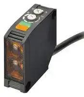
Photoelectric Sensor, E3JK Series, 11 m, Retroreflective, Relay, 24 V to 240 V
- Manufacturer: OMRON INDUSTRIAL AUTOMATION
- Product type:
- Sensor Output:Relay; Sensing Range Max:11m; Supply Voltage DC Min:24V; Supply Voltage DC Max:240V; Output Current:3A; Product Range:E3JK Series; SVHC:No SVHC (20-Jun-2016)
- IP Rating: IP64
- Output Type: SPDT Relay
- Sensor Type: Photoelectric Sensors
- Light Source: 624nm Red LED
- Product Range: E3JK Series
- Qualification: -
- Sensing Method: Retroreflective
- Connection Method: Cable
- Sensing Range Max: 11m
- Sensor Output Type: Relay
- Supply Voltage Max: 240VDC
- Supply Voltage Min: 24VDC
- Sensing Distance Max: 7m
- Supply Voltage DC Max: 240V
- Supply Voltage DC Min: 24V
- Operating Temperature Max: 55°C
- Operating Temperature Min: -25°C
| Delivery and price | |
|---|---|
| Units per pack | 50 |
| Price | 89.67 € |
| Current stock | 10+ |
| Lead time | 30 days |
**New Product**

## **Built-in Power Supply Photoelectric Sensor E3JK <NEW>**

## **Long-distance Photoelectric Sensor That Supports AC/DC Power Supplies**

- **Long sensing distance that is approximately 8 times that of our conventional model (for the Through-beam and Diffuse-reflective models). (Through-beam: 40 m, Retro-reflective: 7 m, and Diffuse-reflective: 2.5 m.)**

- **Improved visibility:**

- A red LED that makes the spot visible.

- Large indicators that can be seen even from a distance.

- **Improved operability. (Enlarged sensitivity adjuster and operation selector)**

**==> picture [214 x 16] intentionally omitted <==**

**----- Start of picture text -----**<br>
For the most recent information on models that have been certified for<br>safety standards, refer to your OMRON website.<br>**----- End of picture text -----**<br>


- **Freely selectable power supply input (24 to 240 VDC, 24 to 240 VAC).**

- **(Additional types added to the DC type lineup.)**

**Refer to the** _**Safety Precautions**_ **on page 12.**

## **Applications**

## Elevator cage detection

Detection of packages jutting out from their storage location

Pallet detection for agricultural produce conveyors

Workpiece detection for woodworking machines

**1**

**E3JK**

## **Ordering Information**

## **Sensors**

Red light

## **Sensors without Brackets or Reflectors**

|**Power supply**<br>**voltage**|**Sensing method**||**Appearance**|**Sensing distance**|**Sensing distance**|**Sensing distance**|**Sensing distance**|**Sensing distance**|**Output**<br>**configu-**<br>**ration**|**Model**|
|---|---|---|---|---|---|---|---|---|---|---|
|AC/DC power<br>supply<br>selectable<br>type|Through-beam*1<br>(Emitter + Receiver)||||||40|m|Relay<br> <br>|**E3JK-TR11 2M**|
||||||||||||
||||||||||||
|||||||||||**E3JK-TR12 2M**|
|||||||5 m|||||
||||||||||||
||Retro-reflective<br>without MSR function||*3||7<br>[1||*3<br>m<br>00 mm]<br>R1)<br>11 m<br>[100 m|||**E3JK-RR11 2M**|
||||||||||||
||||||||||||
|||||(When u|sing E39-||||||
||||||||||||
|||||||||<br>m]|||
||||||||||||
||||||||||||
|||||(When u|sing E39-||R2)||||
||||||||||||
||Retro-reflective<br>with MSR function||||6<br>[10||*3<br>m<br>0 mm]<br>R1)|]||**E3JK-RR12 2M**|
||||||||||||
||||||||||||
|||||(When u|sing E39-||||||
||||||||||||
||||||||10 m<br>[100 mm||||
||||||||||||
||||||||||||
|||||(When u|sing E39-||R2)||||
||||||||||||
||Diffuse-reflective|||2|.5 m|||||**E3JK-DR11 2M**|
||||||||||||
||||||||||||
|||||300|mm|||||**E3JK-DR12 2M**|
|DC|Through-beam*1<br>(Emitter + Receiver)||||||40|m|NPN<br>|**E3JK-TN11 2M**|
||||||||||||
||||||||||PNP<br>|**E3JK-TP11 2M**|
||||||||||||
||||||||||NPN|**E3JK-TN12 2M**|
|||||||5 m|||||
||||||||||PNP|**E3JK-TP12 2M**|
||||||||||||
||Retro-reflective<br>without MSR function||*2||7<br>[1||*3<br>m<br>00 mm]<br>R1)<br>11 m<br>[100 m||NPN|**E3JK-RN11 2M**|
||||||||||||
||||||||||||
|||||(When u|sing E39-||||||
||||||||||||
||||||||||PNP<br>|**E3JK-RP11 2M**|
|||||||||<br>m]|||
||||||||||||
|||||(When u|sing E39-||R2)||||
||||||||||||
||Retro-reflective<br>with MSR function||||6<br>[10||*3<br>m<br>0 mm]<br>1)|]|NPN|**E3JK-RN12 2M**|
||||||||||||
||||||||||||
|||||(When u|sing E39-R||||||
||||||||||||
||||||||||PNP|**E3JK-RP12 2M**|
||||||||10 m<br>[100 mm||||
||||||||||||
||||||||||||
|||||(When u|sing E39-||R2)||||
||||||||||||
||Diffuse-reflective|||2|.5 m||||NPN<br>|**E3JK-DN11 2M**<br>|
||||||||||||
||||||||||PNP|**E3JK-DP11 2M**|
|||||300|mm||||NPN|**E3JK-DN12 2M**|
||||||||||PNP|**E3JK-DP12 2M**|


- *1. Through-beam Sensors are sold in sets that include both the Emitter and Receiver.

- *2. A Reflector is not included. Purchase a Reflector separately to match the intended use of the Sensor.

- *3. Values in parentheses indicate the minimum required distances between the Sensors and Reflectors.

**2**

**E3JK**

## **Sensors**

Red light

**Sensors with Brackets and Reflectors (The model numbers contain (“-C.”)**

|**Power supply**<br>**voltage**|**Sensing method**||**Appearance**|**Appearance**|**Appearance**|**Sensing distance**|**Sensing distance**|**Sensing distance**|**Sensing distance**|**Sensing distance**|**Output**<br>**configu-**<br>**ration**|**Model**|
|---|---|---|---|---|---|---|---|---|---|---|---|---|
|AC/DC power<br>supply select-<br>able|Through-beam*1<br>(Emitter + Receiv-<br>er)||||||||40|m|Relay|**E3JK-TR11-C 2M**|
||||||||||||||
||||||||||||||
|||||||||||||**E3JK-TR12-C 2M**|
|||||||||5m|||||
||||||||||||||
||Retro-reflective<br>without MSR func-<br>tion||||||7<br>[||*2<br>m<br>100mm]<br>R1)|m]||**E3JK-RR11-C 2M**|
||||||||||||||
||||||||||||||
|||||||(When u|sing E39-||||||
||||||||||||||
||||||||||11m<br>[100m||||
||||||||||||||
|||||||(When u|sing E39-||R2)||||
||||||||||||||
||Retro-reflective<br>with MSR function||||||6<br>[1||*2<br>m<br>00mm]<br>R1)|]||**E3JK-RR12-C 2M**|
||||||||||||||
||||||||||||||
|||||||(When u|sing E39-||||||
||||||||||||||
||||||||||10m<br>[100mm||||
||||||||||||||
||||||||||||||
|||||||(When u|sing E39-||R2)||||
||||||||||||||
||Diffuse-reflective||||||2.5m|||||**E3JK-DR11-C 2M**|
|||||||300|mm|||||**E3JK-DR12-C 2M**|


*1. Through-beam Sensors are sold in sets that include both the Emitter and Receiver.

*2. Values in parentheses indicate the minimum required distances between the Sensors and Reflectors.

## **Accessories (Order Separately)**

**Reflectors (A Reflector is required for Retro-reflective Sensors.) [Refer to** _**Dimensions**_ **on page 14.] The E39-R1 is enclosed with Sensors with model numbers that contain “-C.”**

|**Name**|**Sensing distance (rated value)**|**Sensing distance (rated value)**|**Model**|**Quantity**|
|---|---|---|---|---|
|Reflectors|E3JK**-R**@**11**|7 m [100 mm]*|**E39-R1**|1|
||E3JK**-R**@**12**|6 m [100 mm]*|||
||E3JK**-R**@**11**|9 m [100 mm]*|**E39-R1S**|1|
||E3JK**-R**@**12**|7 m [100 mm]*|||
||E3JK**-R**@**11**|11 m [100 mm]*|**E39-R2**|1|
||E3JK**-R**@**12**|10 m [100 mm]*|||


**Note:** Refer to _Engineering Data_ on page 9 for details.

*Values in parentheses indicate the minimum required distances between the Sensors and Reflectors.

**Mounting Bracket [Refer to** _**Dimensions**_ **on page 14.] A Mounting Bracket is enclosed with Sensors with model numbers that contain “-C.”**

|**Appearance**|**Model**|**Quantity**|
|---|---|---|
||**E39-L40**|1|


**Note: 1.** When using a Through-beam Sensor, order one Mounting Bracket for the Receiver and one for the Emitter. **2.** For details, refer to _Mounting Brackets_ on E39-L/E39-S/E39-R which can be accessed from your OMRON website.

**3**

**E3JK**

## **Ratings and Specifications**

|**Sensing method**|**Sensing method**|**Through-beam**|**Through-beam**|**Through-beam**|
|---|---|---|---|---|
|**Item**<br>**Model**||**E3JK-TR11-@**|**E3JK-TN11**|**E3JK-TP11**|
|**Sensing distance**||40 m|||
|**Standard sensing object**||Opaque: 17-mm dia. min.|||
|**Differential travel**||−|||
|**Directional angle**||Both Emitter and Receiver 3°min.|||
|**Light source (wavelength)**||Red LED (624 nm)|||
|**Power supply**|**voltage**|24 to 240 VDC±10%,<br>ripple (p-p): 10% max.<br>24 to 240 VAC±10%, 50/60 Hz|10 to 30 VDC, including ripple (p-p): 10%||
|**Power**<br>**consumption**|**DC**|3 W max. (Emitter 1.5 W max.<br>Receiver 1.5 W max.)|40 mA max. (Emitter 25 mA max. Receiver 15 mA max.)||
||**AC**|3 W max. (Emitter 1.5 W max.<br>Receiver 1.5 W max.)|−||
|**Control output**||Relay output SPDT, 250 VAC,<br>3 A max. (cosϕ= 1), 5 VDC,<br>10 mA min., Light-ON/Dark-ON<br>selectable|Load power supply voltage: 30 V max., Load current: 100 mA max.,<br>Residual voltage: 3 V max., open-collector output (NPN/PNP<br>output depending on model), Light-ON/Dark-ON selectable||
|**Life**<br>**expectancy**<br>**(relay output)**|**Mechanical**|50,000,000 times min. (switching frequency: 18,000 times/h)|||
||**Electrical**|100,000 times min. (switching frequency: 1,800 times/h)|||
|**Response time**||20 ms max.|1 ms max.||
|**Sensitivity adjustment**||One-turn adjuster   Receiver (E3JK-T@@@-D) only|||
|**Ambient illumination**<br>**(Receiver side)**||Incandescent lamp: 3,000 lx max., Sunlight: 11,000 lx max.|||
|**Ambient temperature range**||Operating:−25°C to 55°C, Storage:−40°C to 70°C (with no icing or condensation)|||
|**Ambient humidity range**||Operating: 35% to 85%, Storage: 35% to 95% (with no condensation)|||
|**Insulation resistance**||20 MΩmin. at 500 VDC|||
|**Dielectric strength**||1,500 VAC, 50/60 Hz for 1 min|||
|**Vibration**<br>**resistance**|**Destruction**|10 to 55 Hz with a 1.5 mm double amplitude for 2 hours each in X, Y, and Z directions|||
||**Malfunction**|10 to 55 Hz with a 1.5 mm double amplitude for 2 hours each in X, Y, and Z directions|||
|**Shock**<br>**resistance**|**Destruction**|500 m/s2for 3 times each in X, Y, and Z directions|||
||**Malfunction**|100 m/s2for 3 times each in X, Y,<br>and Z directions|500 m/s2for 3 times each in X, Y, and Z directions||
|**Degree of protection**||IEC 60529 IP64|||
|**Connection method**||Pre-wired (standard length: 2 m)|||
|**Weight (packed state)**||Approx. 350 g|Approx. 300 g||
|**Material**|**Case**|ABS (Acrylonitril Butadiene Styrene)|||
||**Lens/Display**<br>**window**|Methacrylic resin|||
||**Adjuster**|POM|||
||**Cable**|PVC|||
|**Bending radius of cable**||R18|||
|**Accessories**||Instruction manual and Mounting Bracket (E3JK-TR11-C only)|||


**4**

**E3JK**

|**Sensing method**|**Sensing method**|**Through-beam**|**Through-beam**|**Through-beam**|
|---|---|---|---|---|
|**Item**<br>**Model**||**E3JK-TR12-@**|**E3JK-TN12**|**E3JK-TP12**|
|**Sensing distance**||5 m|||
|**Standard sensing object**||Opaque: 17-mm dia. min.|||
|**Differential travel**||−|||
|**Directional angle**||Both Emitter and Receiver 3°min.|||
|**Light source (wavelength)**||Red LED (624 nm)|||
|**Power supply**|**voltage**|24 to 240 VDC±10%,<br>ripple (p-p): 10% max.<br>24 to 240 VAC±10%, 50/60 Hz|10 to 30 VDC, including ripple (p-p): 10%||
|**Power**<br>**consumption**|**DC**|3 W max. (Emitter 1.5 W max.<br>Receiver 1.5 W max.)|40 mA max. (Emitter 25 mA max. Receiver 15 mA max.)||
||**AC**|3 W max. (Emitter 1.5 W max.<br>Receiver 1.5 W max.)|−||
|**Control output**||Relay output SPDT, 250 VAC,<br>3 A max. (cosϕ= 1), 5 VDC,<br>10 mA min., Light-ON/Dark-ON<br>selectable|Load power supply voltage: 30 V max., Load current: 100 mA max.,<br>Residual voltage: 3 V max., open-collector output (NPN/PNP<br>output depending on model), Light-ON/Dark-ON selectable||
|**Life**<br>**expectancy**<br>**(relay output)**|**Mechanical**|50,000,000 times min. (switching frequency: 18,000 times/h)|||
||**Electrical**|100,000 times min. (switching frequency: 1,800 times/h)|||
|**Response time**||20 ms max.|1 ms max.||
|**Sensitivity adjustment**||One-turn adjuster   Receiver (E3JK-T@@@-D) only|||
|**Ambient illumination**<br>**(Receiver side)**||Incandescent lamp: 3,000 lx max., Sunlight: 11,000 lx max.|||
|**Ambient temperature range**||Operating:−25°C to 55°C, Storage:−40°C to 70°C (with no icing or condensation)|||
|**Ambient humidity range**||Operating: 35% to 85%, Storage: 35% to 95% (with no condensation)|||
|**Insulation resistance**||20 MΩmin. at 500 VDC|||
|**Dielectric strength**||1,500 VAC, 50/60 Hz for 1 min|||
|**Vibration**<br>**resistance**|**Destruction**|10 to 55 Hz with a 1.5 mm double amplitude for 2 hours each in X, Y, and Z directions|||
||**Malfunction**|10 to 55 Hz with a 1.5 mm double amplitude for 2 hours each in X, Y, and Z directions|||
|**Shock**<br>**resistance**|**Destruction**|500 m/s2for 3 times each in X, Y, and Z directions|||
||**Malfunction**|100 m/s2for 3 times each in X, Y,<br>and Z directions|500 m/s2for 3 times each in X, Y, and Z directions||
|**Degree of protection**||IEC 60529 IP64|||
|**Connection method**||Pre-wired (standard length: 2 m)|||
|**Weight (packed state)**||Approx. 350 g|Approx. 300 g||
|**Material**|**Case**|ABS (Acrylonitril Butadiene Styrene)|||
||**Lens/Display**<br>**window**|Methacrylic resin|||
||**Adjuster**|POM|||
||**Cable**|PVC|||
|**Bending radius of cable**||R18|||
|**Accessories**||Instruction manual and Mounting Bracket (E3JK-TR12-C only)|||


**5**

**E3JK**

|**Sensing method**|**Sensing method**|**Retro-reflective (without MSR function)**|**Retro-reflective (without MSR function)**|**Retro-reflective (without MSR function)**|
|---|---|---|---|---|
|**Item**<br>**Model**||**E3JK-RR11-@**|**E3JK-RN11**|**E3JK-RP11**|
|**Sensing distance**||7 m [100 mm]*(When using E39-R1), 11 m [100 mm]*(When using E39-R2)|||
|**Standard sensing object**||Opaque: 75-mm dia. min.|||
|**Differential travel**||−|||
|**Directional angle**||1.5°min.|||
|**Light source (wavelength)**||Red LED (624 nm)|||
|**Power supply**|**voltage**|24 to 240 VDC±10%,<br>ripple (p-p): 10% max.<br>24 to 240 VAC±10%, 50/60 Hz|10 to 30 VDC, including ripple (p-p): 10%||
|**Power**<br>**consumption**|**DC**|2 W max.|30 mA max.||
||**AC**|2 W max.|−||
|**Control output**||Relay output SPDT, 250 VAC,<br>3 A max. (cosϕ= 1), 5 VDC,<br>10 mA min., Light-ON/Dark-ON<br>selectable|Load power supply voltage: 30 V max., Load current: 100 mA max.,<br>Residual voltage: 3 V max., open-collector output (NPN/PNP<br>output depending on model), Light-ON/Dark-ON selectable||
|**Life**<br>**expectancy**<br>**(relay output)**|**Mechanical**|50,000,000 times min. (switching frequency: 18,000 times/h)|||
||**Electrical**|100,000 times min. (switching frequency: 1,800 times/h)|||
|**Response time**||20 ms max.|1 ms max.||
|**Sensitivity adjustment**||One-turn adjuster|||
|**Ambient illumination**<br>**(Receiver side)**||Incandescent lamp: 3,000 lx max., Sunlight: 11,000 lx max.|||
|**Ambient temperature range**||Operating:−25°C to 55°C, Storage:−40°C to 70°C (with no icing or condensation)|||
|**Ambient humidity range**||Operating: 35% to 85%, Storage: 35% to 95% (with no condensation)|||
|**Insulation resistance**||20 MΩmin. at 500 VDC|||
|**Dielectric strength**||1,500 VAC, 50/60 Hz for 1 min|||
|**Vibration**<br>**resistance**|**Destruction**|10 to 55 Hz with a 1.5 mm double amplitude for 2 hours each in X, Y, and Z directions|||
||**Malfunction**|10 to 55 Hz with a 1.5 mm double amplitude for 2 hours each in X, Y, and Z directions|||
|**Shock**<br>**resistance**|**Destruction**|500 m/s2for 3 times each in X, Y, and Z directions|||
||**Malfunction**|100 m/s2for 3 times each in X, Y,<br>and Z directions|500 m/s2for 3 times each in X, Y, and Z directions||
|**Degree of protection**||IEC 60529 IP64|||
|**Connection method**||Pre-wired (standard length: 2 m)|||
|**Weight (packed state)**||Approx. 180 g|Approx. 160 g||
|**Material**|**Case**|ABS (Acrylonitril Butadiene Styrene)|||
||**Lens/Display**<br>**window**|Methacrylic resin|||
||**Adjuster**|POM|||
||**Cable**|PVC|||
|**Bending radius of cable**||R18|||
|**Accessories**||Instruction manual, Mounting Bracket (E3JK-RR11-C only), and Reflector (E3JK-RR11-C only)|||


*Values in parentheses indicate the minimum required distances between the Sensors and Reflectors.

**6**

**E3JK**

|**Sensing method**|**Sensing method**|**Retro-reflective (with MSR function)**|**Retro-reflective (with MSR function)**|**Retro-reflective (with MSR function)**|
|---|---|---|---|---|
|**Item**<br>**Model**||**E3JK-RR12-@**|**E3JK-RN12**|**E3JK-RP12**|
|**Sensing distance**||6 m [100 mm]*(When using E39-R1), 10 m [100 mm]*(When using E39-R2)|||
|**Standard sensing object**||Opaque: 75-mm dia. min.|||
|**Differential travel**||−|||
|**Directional angle**||1.5°min.|||
|**Light source (wavelength)**||Red LED (624 nm)|||
|**Power supply**|**voltage**|24 to 240 VDC±10%,<br>ripple (p-p): 10% max.<br>24 to 240 VAC±10%, 50/60 Hz|10 to 30 VDC, including ripple (p-p): 10%||
|**Power**<br>**consumption**|**DC**|2 W max.|30 mA max.||
||**AC**|2 W max.|−||
|**Control output**||Relay output SPDT, 250 VAC,<br>3 A max. (cosϕ= 1), 5 VDC,<br>10 mA min., Light-ON/Dark-ON<br>selectable|Load power supply voltage: 30 V max., Load current: 100 mA max.,<br>Residual voltage: 3 V max., open-collector output (NPN/PNP<br>output depending on model), Light-ON/Dark-ON selectable||
|**Life**<br>**expectancy**<br>**(relay output)**|**Mechanical**|50,000,000 times min. (switching frequency: 18,000 times/h)|||
||**Electrical**|100,000 times min. (switching frequency: 1,800 times/h)|||
|**Response time**||20 ms max.|1 ms max.||
|**Sensitivity adjustment**||One-turn adjuster|||
|**Ambient illumination**<br>**(Receiver side)**||Incandescent lamp: 3,000 lx max., Sunlight: 11,000 lx max.|||
|**Ambient temperature range**||Operating:−25°C to 55°C, Storage:−40°C to 70°C (with no icing or condensation)|||
|**Ambient humidity range**||Operating: 35% to 85%, Storage: 35% to 95% (with no condensation)|||
|**Insulation resistance**||20 MΩmin. at 500 VDC|||
|**Dielectric strength**||1,500 VAC, 50/60 Hz for 1 min|||
|**Vibration**<br>**resistance**|**Destruction**|10 to 55 Hz with a 1.5 mm double amplitude for 2 hours each in X, Y, and Z directions|||
||**Malfunction**|10 to 55 Hz with a 1.5 mm double amplitude for 2 hours each in X, Y, and Z directions|||
|**Shock**<br>**resistance**|**Destruction**|500 m/s2for 3 times each in X, Y, and Z directions|||
||**Malfunction**|100 m/s2for 3 times each in X, Y,<br>and Z directions|500 m/s2for 3 times each in X, Y, and Z directions||
|**Degree of protection**||IEC 60529 IP64|||
|**Connection method**||Pre-wired (standard length: 2 m)|||
|**Weight (packed state)**||Approx. 180 g|Approx. 160 g||
|**Material**|**Case**|ABS (Acrylonitril Butadiene Styrene)|||
||**Lens/Display**<br>**window**|Methacrylic resin|||
||**Adjuster**|POM|||
||**Cable**|PVC|||
|**Bending radius of cable**||R18|||
|**Accessories**||Instruction manual, Mounting Bracket (E3JK-RR12-C only), and Reflector (E3JK-RR12-C only)|||


*Values in parentheses indicate the minimum required distances between the Sensors and Reflectors.

**7**

**E3JK**

|**Sensing method**|**Sensing method**|**Diffuse-reflective**|**Diffuse-reflective**|**Diffuse-reflective**|**Diffuse-reflective**|**Diffuse-reflective**|**Diffuse-reflective**|
|---|---|---|---|---|---|---|---|
|**Item**<br>**Model**||**E3JK-DR11-@**|**E3JK-DR12-@**|**E3JK-DN11**|**E3JK-DP11**|**E3JK-DN12**|**E3JK-DP12**|
|**Sensing distance**||White paper<br>(300×300<br>mm): 2.5 m|White paper<br>(100×100<br>mm): 300 mm|White paper (300×300 mm):<br>2.5 m||White paper (100×100 mm):<br>300 mm||
|**Standard sensing object**||−||||||
|**Differential travel**||20% max. of sensing distance||||||
|**Directional angle**||−||||||
|**Light source (wavelength)**||Red LED (624 nm)||||||
|**Power supply**|**voltage**|24 to 240 VDC±10%,<br>ripple (p-p): 10% max.<br>24 to 240 VAC±10%, 50/60 Hz||10 to 30 VDC, including ripple (p-p): 10%||||
|**Power**<br>**consumption**|**DC**|2 W max.||30 mA max.||||
||**AC**|2 W max.||−||||
|**Control output**||Relay output SPDT, 250 VAC,<br>3 A max. (cosϕ= 1), 5 VDC,<br>10 mA min., Light-ON/Dark-ON<br>selectable||Load power supply voltage: 30 V max., Load current: 100 mA max.,<br>Residual voltage: 3 V max., open-collector output (NPN/PNP<br>output depending on model), Light-ON/Dark-ON selectable||||
|**Life**<br>**expectancy**<br>**(relay output)**|**Mechanical**|50,000,000 times min. (switching frequency: 18,000 times/h)||||||
||**Electrical**|100,000 times min. (switching frequency: 1,800 times/h)||||||
|**Response time**||20 ms max.||1 ms max.||||
|**Sensitivity adjustment**||One-turn adjuster||||||
|**Ambient illumination**<br>**(Receiver side)**||Incandescent lamp: 3,000 lx max., Sunlight: 11,000 lx max.||||||
|**Ambient temperature range**||Operating:−25°C to 55°C, Storage:−40°C to 70°C (with no icing or condensation)||||||
|**Ambient humidity range**||Operating: 35% to 85%, Storage: 35% to 95% (with no condensation)||||||
|**Insulation resistance**||20 MΩmin. at 500 VDC||||||
|**Dielectric strength**||1,500 VAC, 50/60 Hz for 1 min||||||
|**Vibration**<br>**resistance**|**Destruction**|10 to 55 Hz with a 1.5 mm double amplitude for 2 hours each in X, Y, and Z directions||||||
||**Malfunction**|10 to 55 Hz with a 1.5 mm double amplitude for 2 hours each in X, Y, and Z directions||||||
|**Shock**<br>**resistance**|**Destruction**|500 m/s2for 3 times each in X, Y, and Z directions||||||
||**Malfunction**|100 m/s2for 3 times each in X, Y,<br>and Z directions||500 m/s2for 3 times each in X, Y, and Z directions||||
|**Degree of protection**||IEC 60529 IP64||||||
|**Connection method**||Pre-wired (standard length: 2 m)||||||
|**Weight (packed state)**||Approx. 180 g||Approx. 160 g||||
|**Material**|**Case**|ABS (Acrylonitril Butadiene Styrene)||||||
||**Lens/Display**<br>**window**|Methacrylic resin||||||
||**Adjuster**|POM||||||
||**Cable**|PVC||||||
|**Bending radius of cable**||R18||||||
|**Accessories**||Instruction manual and Mounting Bracket (E3JK-DR1**@**-C only)||||||


**8**

**E3JK**

**Engineering Data (Reference Value)**

## **Parallel Operating Range**

## **Through-beam**

**==> picture [512 x 693] intentionally omitted <==**

**----- Start of picture text -----**<br>
E3JK-T @ 11 E3JK-T @ 12<br>2.0 0.5<br>1.5 0.4<br>0.3<br>1.0<br>0.2<br>0.5<br>0.1<br>0 0<br>−0.5 −0.1<br>−0.2<br>−1.0<br>−0.3<br>−1.5 Y −0.4 Y<br>−2.0 X −0.5 X<br>0 20 40 60 80 100 0 2 4 6 8 10<br>Sensing distance (m) Sensing distance (m)<br>Retro-reflective<br>E3JK-R @@ 1 + E39-R1 E3JK-R @@ 1 + E39-R1S E3JK-R @@ 1 + E39-R2<br>150 Reflector: E39-R1 200 Reflector: E39-R1S 250 Reflector: E39-R2<br>200<br>150<br>100<br>150<br>100<br>100<br>50<br>50 50<br>0 0 0<br>−50<br>−50<br>50 −100<br>−100<br>−150<br>−100 Y −150 Y −200 Y<br>−150 X −200 X −250 X<br>0 2 4 6 8 10 12 0 5 10 15 0 5 10 15 20<br>Sensing distance (m) Sensing distance (m) Sensing distance (m)<br>E3JK-R @@ 2 + E39-R1 E3JK-R @@ 2 + E39-R1S E3JK-R @@ 2 + E39-R2<br>150 200 250<br>Reflector: E39-R1 Reflector: E39-R1S Reflector: E39-R2<br>200<br>150<br>100<br>150<br>100<br>100<br>50<br>50 50<br>0 0 0<br>−50 −50<br>−50 −150<br>−100<br>−200<br>−100 Y Y Y<br>−150 −250<br>−150 X −200 X −250 X<br>0 2 4 6 8 10 0 5 10 15 0 5 10 15 20<br>Sensing distance (m) Sensing distance (m) Sensing distance (m)<br>Operating Range<br>Diffuse-reflective<br>E3JK-D @@ 1 E3JK-D @@ 2<br>50 30<br>Sensing object: White paper (300 × 300 mm) Sensing object: White paper (100 × 100 mm)<br>40 Y<br>Y 20<br>30<br>X<br>20 X 10<br>10<br>0 0<br>−10<br>−10<br>−20<br>−30 −20<br>−40<br>−50 −30<br>0 2 4 6 8 0 200 400 600 800 1000<br>Distance X (m) Distance X (mm)<br>Parallel distance (m) Parallel distance (m)<br>Parallel distance (mm) Parallel distance (mm) Parallel distance (mm)<br>Parallel distance (mm) Parallel distance (mm) Parallel distance (mm)<br>Distance Y (mm) Distance Y (mm)<br>**----- End of picture text -----**<br>


**9**

**E3JK**

## **Excess Gain Ratio vs. Set Distance**

## **Through-beam**

## **E3JK-T** @ **11**

## **E3JK-T** @ **12**

**==> picture [332 x 149] intentionally omitted <==**

**----- Start of picture text -----**<br>
100 100<br>10 10<br>Operatinglevel 1 Operatinglevel 1<br>0.1 0.1<br>0 20 40 60 80 100 0 5 10 15 20<br>Distance (m) Distance (m)<br>Excess gain ratio Excess gain ratio<br>**----- End of picture text -----**<br>


## **Retro-reflective**

## **E3JK-R** @@ **1** + **E39-R1**

## **E3JK-R** @@ **1** + **E39-R1S**

**==> picture [327 x 312] intentionally omitted <==**

**----- Start of picture text -----**<br>
100 Reflector: E39-R1 100 Reflector: E39-R1S<br>10 10<br>Operatinglevel 1 Operatinglevel 1<br>0.1 0.1<br>0 2 4 6 8 10 12 0 2 4 6 8 10 12 14 16 18 20<br>Distance (m) Distance (m)<br>E3JK-R @@ 2 + E39-R1 E3JK-R @@ 2 + E39-R1S<br>100 Reflector: E39-R1 100 Reflector: E39-R1S<br>10 10<br>Operatinglevel 1 Operatinglevel 1<br>0.1 0.1<br>0 2 4 6 8 10 12 0 2 4 6 8 10 12 14 16 18 20<br>Distance (m) Distance (m)<br>Excess gain ratio Excess gain ratio<br>Excess gain ratio Excess gain ratio<br>**----- End of picture text -----**<br>


## **E3JK-R** @@ **2** + **E39-R1**

## **E3JK-R** @@ **1** + **E39-R2**

**==> picture [149 x 312] intentionally omitted <==**

**----- Start of picture text -----**<br>
100 Reflector: E39-R2<br>10<br>Operatinglevel 1<br>0.1<br>0 2 4 6 8 10 12 14 16 18 20<br>Distance (mm)<br>E3JK-R @@ 2 + E39-R2<br>100 Reflector: E39-R2<br>10<br>Operatinglevel 1<br>0.1<br>0 2 4 6 8 10 12 14 16 18 20<br>Distance (m)<br>Excess gain ratio<br>Excess gain ratio<br>**----- End of picture text -----**<br>


## **Diffuse-reflective**

## **E3JK-D** @@ **1**

## **E3JK-D** @@ **2**

**==> picture [319 x 148] intentionally omitted <==**

**----- Start of picture text -----**<br>
100 Sensing object: White paper (300 × 300 mm) 100 Sensing object: White paper (100 × 100 mm)<br>10<br>10<br>Operatinglevel 1<br>Operatinglevel 1 0 2 4 6 0.1 0 100 200 300 400 500<br>Distance (m) Distance (mm)<br>Excess gain ratio Excess gain ratio<br>**----- End of picture text -----**<br>


**10**

**E3JK**

## **I/O Circuit Diagrams**

## **Relay Output Models**

|**Model**|**Timing chart**|**Timing chart**|**Timing chart**|**Timing chart**|**Timing chart**|**Timing chart**|**Timing chart**|||**Output circuit**|**Output circuit**|**Output circuit**|
|---|---|---|---|---|---|---|---|---|---|---|---|---|
||**Light-ON**||||**Dark-ON**||||||||
|E3JK-TR11-L*<br>E3JK-TR12-L*|||||||||Power<br>Indicator<br>(green)|Photoelectric<br>Sensor<br>main<br>Circuit|Brown|Power<br>Source<br>24 to 240 VAC<br>24 to 240 VDC|
||||||||||||Blue|Po<br>Sou<br>24 to 240 VAC<br>24 to 240 VDC|
||||||||||||||
|E3JK-TR11-D*<br>E3JK-TR12-D*<br>E3JK-RR11<br>E3JK-RR12<br>E3JK-DR11<br>E3JK-DR12|Operation Indicator<br>(orange)<br>Relay<br>Output Tc-Tb<br>Output Tc-Ta<br>Incident light<br>No incident light<br>ON<br>OFF<br>Operate<br>Reset<br>Conducting<br>Not conducting<br>Conducting<br>Not conducting||||Operation Indicator<br>(orange)<br>Relay<br>Output Tc-Tb<br>Output Tc-Ta<br>Incident light<br>No incident light<br>ON<br>OFF<br>Operate<br>Reset<br>Conducting<br>Not conducting<br>Conducting<br>Not conducting|||Stability<br>Indicator<br>(green)|||Power<br>Source<br>24 to 240 VAC<br>24 to 240 VDC<br>Brown<br>Blue<br>White<br>Black<br>Gray<br>Ta<br>Contact output (SPDT),<br>250 VAC, 3 A max.,<br>5 VDC, 10 mA min.<br>Tb<br>Tc||
||||||||||Stability<br>Indicator<br>(green)|Photoelectric<br>Sensor<br>main<br>Circuit<br>Operation Indicator<br>(orange)|Brown||
||||||||||||Blue|Po<br>Sou<br>24 to 240 VAC<br>24 to 240 VDC|
||||||||||||White<br>Black<br>Gray||
||||||||||||||
|||<br>|||||||||||
||||||||||||||
||||||||||||||
||||||||||||||
|**DC SSR Output Models**|||||||||||||
|**Model**|||**Timing chart**|||||||**Output circuit**|||
||**Light-ON**||||**Dark-ON**||||||||
|E3JK-TN11-L*<br>E3JK-TP11-L*<br>E3JK-TN12-L*<br>E3JK-TP12-L*||||||||Power<br>Indicator<br>(green)||Photoelectric<br>Sensor<br>main<br>Circuit<br>10 to 30 VDC<br>0V<br>Brown<br>Blue|||
|E3JK-TN11-D*<br>E3JK-TN12-D*<br>E3JK-RN11<br>E3JK-RN12<br>E3JK-DN11<br>E3JK-DN12|Operation Indicator<br>(orange)<br>Output<br>transistor<br>Load<br>(e.g., relay)<br>Incident light<br>No incident light<br>ON<br>OFF<br>ON<br>OFF<br>Operate<br>Reset||||Operation Indicator<br>(orange)<br>Output<br>transistor<br>Load<br>(e.g., relay)<br>Incident light<br>No incident light<br>ON<br>OFF<br>ON<br>OFF<br>Operate<br>Reset|||Stability<br>Indicator<br>(green)||Photoelectric<br>Sensor<br>main<br>Circuit<br>10 to 30 VDC<br>0V<br>Brown<br>Black<br>Blue<br>100 mA max.<br>Load<br>Operation Indicator<br>(orange)|||
||||||ncen g<br>N inidnt lih|<br>|||||||
|||<br>|||Operation Indicator<br>o ce g<br>ON||||||||
||||||<br>(orange)<br>OFF<br>O||||||||
||||||Output<br><br><br>||||||||
||||||transistor<br>OF<br>O||||||||
||||||Load<br> <br>perate<br>Reset||||||||
||||||(e.g., relay)<br>||||||||
|E3JK-TP11-D*<br>E3JK-TP12-D*<br>E3JK-RP11<br>E3JK-RP12<br>E3JK-DP11<br>E3JK-DP12|Operation Indicator<br>(orange)<br>Output<br>transistor<br>Load<br>(e.g., relay)<br>Incident light<br>No incident light<br>ON<br>OFF<br>ON<br>OFF<br>Operate<br>Reset||||Iidt lih|||Stability<br>Indicator<br>(green)||Photoelectric<br>Sensor<br>main<br>Circuit<br>10 to 30 VDC<br>0V<br>Brown<br>Black<br>Blue<br>100 mA max.<br>Load<br>Operation Indicator<br>(orange)|||
||||||ncen g<br>N iidt lih|<br>|||||||
|||<br>|||Operation Indicator<br>o ncen g<br>ON||||||||
||||||<br>(orange)<br>OFF<br>O||||||||
||||||Output<br>transistor<br><br>OFF||||||||
||||||Load<br> <br>Operate<br>Reset||||||||
||||||(e.g., relay)<br>||||||||


**Note:** Connect the brown cable to any polarity and the blue cable to the power supply because there is no polarity on the Emitter side.

*For the Through-beam Sensor, the Emitter is listed as E3JK-T@11-L, E3JK-T@12-L and the Receiver is listed as E3JK-T@11-D, E3JK-T@12-D in the table. Confirm the models to order in “Ordering Information.”

**11**

## **E3JK**

## **Safety Precautions**

## **Refer to** _**Warranty and Limitations of Liability**_ **.**

## **WARNING**

**This product is not designed or rated for ensuring safety of persons either directly or indirectly. Do not use it for such purposes.**

## **Caution**

**Do not wire the product incorrectly. Do not use this product with a damaged case or cable.**

**Do not disassemble, repair, or modify this product. Doing so may lead to explosion, fire, or product failure.**

## **Precautions for Safe Use**

The following precautions must be observed to ensure safe operation of the Sensor.

1. Do not use the Sensor in environments subject to flammable, explosive or corrosive gases.

2. Do not use this product in an environment in which oil or chemicals are present.

3. Do not use this product under water, in the rain, or outdoors.

4. Do not use this product under conditions that exceed or in an environment that exceeds the ratings.

5. When using an AC power supply, do not use a power supply that includes high frequencies (such as an inverter).

6. Do not use this product in a location subject to direct sunlight.

7. Do not use this product in a location in which the product will be subject to direct vibrations or impacts.

8. Do not use thinner, alcohol, or other organic solvents with this product.

9. When disposing of the Sensor, treat it as industrial waste.

## **Precautions for Correct Use**

- If the product is wired to high-voltage power lines and power lines in the same pipe or the same duct, the product may malfunction or be damaged due to induction. Therefore, in principle, perform these two types of wiring separately or use shielded cords.

- Do not apply excessive force to the cables.

- When using a commercially available switching regulator, be sure to install an FG (frame ground terminal).

- The time between the product being turned ON and sensing being possible is 100 ms, so wait at least 100 ms after turning the product ON before using it. If the load and the product are connected to different power supplies, be sure to turn the product ON first.

- An output pulse may be generated when the product is turned OFF, so we recommend turning the load or the load line OFF first.

**12**

**E3JK**

**(Unit: mm)**

## **Dimensions**

Tolerance class IT16 applies to dimensions in this datasheet unless otherwise specified.

## **Sensors**

**==> picture [500 x 510] intentionally omitted <==**

**----- Start of picture text -----**<br>
Through-beam <Emitter> Power Indicator (green)<br>E3JK-T @ 1 @ E3JK-T @ 1 @ -L __/| _<br>te i<br>iil) Wo Uh<br>18 50<br>1.3<br>Optical axis<br>4.8 40 50<br>14.7 Two, 4.5-dia. M4<br>x Ln || 20.2 mounting holes 5 x<br>Recommended<br>Torque: 0.8 N(1.2 N⋅m max.)⋅m 5 40 6-dia. vinyl-insulated round cable(Conductor cross section: 0.3 mm [2] , Insulator<br>12.8 diameter: 1.5 mm), Bending radius: R18<br>> = OO<br><Receiver> Operation Indicator (orange) Stability Indicator (green)<br>E3JK-T @ 1 @ -D<br>Il IN 2 UL<br>Sensitivity adjuster Operation selector<br>18 50<br>2<br>Optical axis<br>4.8 40 50<br>14.7 Two, 4.5-dia. M4<br>20.2 mounting holes 5<br>A Recommended  We| a RAN<br>Torque: 0.8 N⋅m 5 6-dia. vinyl-insulated round cable<br>in (1.2 N⋅m max.) as 40 EQ (Conductor cross section: 0.3 mm [2] , Insulator<br>12.8 diameter: 1.5 mm), Bending radius: R18<br>Diffuse-reflective/ Operation Indicator (orange) Stability Indicator (green)<br>Retro-reflective<br>E3JK-R @ 1 @<br>E3JK-D @ 1 @ I A ll<br>Sensitivity adjuster Operation selector<br>=>;<br>fe.) 2 18 | 50<br>ay Emitter -_ 2<br>Optical axis<br>14.7 7 Receiver<br>7 40 50<br>14.7 | 27.2 Two, 4.5-dia. M4  |<br>Ho mounting holes 5 b WS<br>Recommended<br>Torque: 0.8 N⋅m 5 6-dia. vinyl-insulated round cable<br>(1.2 N⋅m max.) 40 (Conductor cross section: 0.3 mm [2] , Insulator<br>diameter: 1.5 mm), Bending radius: R18<br>12.8<br>**----- End of picture text -----**<br>


**==> picture [76 x 41] intentionally omitted <==**

**----- Start of picture text -----**<br>
Diffuse-reflective/<br>Retro-reflective<br>E3JK-R @ 1 @<br>E3JK-D @ 1 @<br>**----- End of picture text -----**<br>


**13**

**E3JK**

## **Accessories**

## **Mounting Bracket (Order separately)**

**==> picture [301 x 200] intentionally omitted <==**

**----- Start of picture text -----**<br>
Mounting Bracket 18 [±][0.1]<br>E39-L40 Radius: 3.2 6-dia. hole Radius: 3.2<br>12 22<br>10 [±][0.1]<br>6.4<br>4 9 6.4<br>Two, Radius: 5<br>42 [±][0.1] 7<br>2 50 Two, Radius: 5<br>40 [±][0.1] 5<br>Two, 4.4-dia. hole<br>Material: Iron Two, Radius: 5<br>Two, Radius: 5.6 Two, Radius: 5<br>Radius: 2.2 60<br>Radius: 56.6 [±][0.1]<br>31.2<br>21.9<br>60°<br>45° Radius: 2.2 24 4.4<br>10°<br>58<br>**----- End of picture text -----**<br>


## **With Mounting Bracket Attached**

**==> picture [344 x 187] intentionally omitted <==**

**----- Start of picture text -----**<br>
47<br>40 [6.4] 21<br>5.6<br>6.6 6-dia. 6.4<br>hole 7<br>18<br>39.5<br>Through-beam Diffuse-reflective/<br>Retro-reflective<br>Mounting Bracket Mounting Bracket<br>Optical axis Mounting Holes<br>Optical axis<br>Two, M6 holes<br>30.2 37.2<br>2 2<br>42<br>**----- End of picture text -----**<br>


## **Reflector (Order separately)**

**==> picture [512 x 138] intentionally omitted <==**

**----- Start of picture text -----**<br>
E39-R1 E39-R2<br>E39-R1S<br>80.8<br>Two, 3.5-dia. holes 40.334 7.5 Four, 3.5-dia. holes 7 74.5 7 7.5<br>7<br>8<br>59.9 52 59.9 52<br>Material:  8 Material:<br>Reflective surface: acrylicRear surface: ABS 1.6 2.7 Reflective surface: acrylicRear surface: ABS 1.6 76.5 34 2.7<br>**----- End of picture text -----**<br>


**14**

## **Terms and Conditions Agreement**

## **Read and understand this catalog.**

Please read and understand this catalog before purchasing the products. Please consult your OMRON representative if you have any questions or comments.

## **Warranties.**

(a) Exclusive Warranty. Omron’s exclusive warranty is that the Products will be free from defects in materials and workmanship for a period of twelve months from the date of sale by Omron (or such other period expressed in writing by Omron). Omron disclaims all other warranties, express or implied.

(b) Limitations. OMRON MAKES NO WARRANTY OR REPRESENTATION, EXPRESS OR IMPLIED, ABOUT NON-INFRINGEMENT, MERCHANTABILITY OR FITNESS FOR A PARTICULAR PURPOSE OF THE PRODUCTS. BUYER ACKNOWLEDGES THAT IT ALONE HAS DETERMINED THAT THE PRODUCTS WILL SUITABLY MEET THE REQUIREMENTS OF THEIR INTENDED USE.

Omron further disclaims all warranties and responsibility of any type for claims or expenses based on infringement by the Products or otherwise of any intellectual property right. (c) Buyer Remedy. Omron’s sole obligation hereunder shall be, at Omron’s election, to (i) replace (in the form originally shipped with Buyer responsible for labor charges for removal or replacement thereof) the non-complying Product, (ii) repair the non-complying Product, or (iii) repay or credit Buyer an amount equal to the purchase price of the non-complying Product; provided that in no event shall Omron be responsible for warranty, repair, indemnity or any other claims or expenses regarding the Products unless Omron’s analysis confirms that the Products were properly handled, stored, installed and maintained and not subject to contamination, abuse, misuse or inappropriate modification. Return of any Products by Buyer must be approved in writing by Omron before shipment. Omron Companies shall not be liable for the suitability or unsuitability or the results from the use of Products in combination with any electrical or electronic components, circuits, system assemblies or any other materials or substances or environments. Any advice, recommendations or information given orally or in writing, are not to be construed as an amendment or addition to the above warranty.

See http://www.omron.com/global/ or contact your Omron representative for published information.

## **Limitation on Liability; Etc.**

OMRON COMPANIES SHALL NOT BE LIABLE FOR SPECIAL, INDIRECT, INCIDENTAL, OR CONSEQUENTIAL DAMAGES, LOSS OF PROFITS OR PRODUCTION OR COMMERCIAL LOSS IN ANY WAY CONNECTED WITH THE PRODUCTS, WHETHER SUCH CLAIM IS BASED IN CONTRACT, WARRANTY, NEGLIGENCE OR STRICT LIABILITY.

Further, in no event shall liability of Omron Companies exceed the individual price of the Product on which liability is asserted.

## **Suitability of Use.**

Omron Companies shall not be responsible for conformity with any standards, codes or regulations which apply to the combination of the Product in the Buyer’s application or use of the Product. At Buyer’s request, Omron will provide applicable third party certification documents identifying ratings and limitations of use which apply to the Product. This information by itself is not sufficient for a complete determination of the suitability of the Product in combination with the end product, machine, system, or other application or use. Buyer shall be solely responsible for determining appropriateness of the particular Product with respect to Buyer’s application, product or system. Buyer shall take application responsibility in all cases.

NEVER USE THE PRODUCT FOR AN APPLICATION INVOLVING SERIOUS RISK TO LIFE OR PROPERTY OR IN LARGE QUANTITIES WITHOUT ENSURING THAT THE SYSTEM AS A WHOLE HAS BEEN DESIGNED TO ADDRESS THE RISKS, AND THAT THE OMRON PRODUCT(S) IS PROPERLY RATED AND INSTALLED FOR THE INTENDED USE WITHIN THE OVERALL EQUIPMENT OR SYSTEM.

## **Programmable Products.**

Omron Companies shall not be responsible for the user’s programming of a programmable Product, or any consequence thereof.

## **Performance Data.**

Data presented in Omron Company websites, catalogs and other materials is provided as a guide for the user in determining suitability and does not constitute a warranty. It may represent the result of Omron’s test conditions, and the user must correlate it to actual application requirements. Actual performance is subject to the Omron’s Warranty and Limitations of Liability.

## **Change in Specifications.**

Product specifications and accessories may be changed at any time based on improvements and other reasons. It is our practice to change part numbers when published ratings or features are changed, or when significant construction changes are made. However, some specifications of the Product may be changed without any notice. When in doubt, special part numbers may be assigned to fix or establish key specifications for your application. Please consult with your Omron’s representative at any time to confirm actual specifications of purchased Product.

## **Errors and Omissions.**

Information presented by Omron Companies has been checked and is believed to be accurate; however, no responsibility is assumed for clerical, typographical or proofreading errors or omissions.

## **OMRON Corporation      Industrial Automation Company**

## **Authorized Distributor:**

## **Tokyo, JAPAN**

## **Contact:  www.ia.omron.com**

_**Regional Headquarters**_

**OMRON EUROPE B.V. OMRON ELECTRONICS LLC Sensor Business Unit** One Commerce Drive Schaumburg, Carl-Benz-Str. 4, D-71154 Nufringen, IL 60173-5302 U.S.A. Germany Tel: (1) 847-843-7900/Fax: (1) 847-843-7787

Tel: (49) 7032-811-0/Fax: (49) 7032-811-199

## **OMRON (CHINA) CO., LTD.**

**OMRON ASIA PACIFIC PTE. LTD.**

No. 438A Alexandra Road # 05-05/08 (Lobby 2), Room 2211, Bank of China Tower, Alexandra Technopark, 200 Yin Cheng Zhong Road, Singapore 119967 PuDong New Area, Shanghai, 200120, China Tel: (65) 6835-3011/Fax: (65) 6835-2711 Tel: (86) 21-5037-2222/Fax: (86) 21-5037-2200

© OMRON Corporation 2013 All Rights Reserved. In the interest of product improvement, specifications are subject to change without notice. **Cat. No. E432-E1-02** 0713(0313)
Updated at April 23, 2026
With a legacy spanning over 80 years, Omron Industrial Automation is a globally recognized leader in the manufacture of advanced industrial control and automation components. Renowned for their reliability and engineering excellence, Omron delivers comprehensive solutions that enhance efficiency, machine safety, and precision across a wide range of manufacturing environments. Our extensive portfolio of Omron products is heavily focused on their industry-leading sensing and switching technologies. We offer a vast selection of sensors, excelling specifically in high-performance proximity sensors, light sensors, and temperature sensors. Complementing this range are robust switching solutions, featuring a deep inventory of power relays, solid-state relays, safety relays, and essential relay accessories designed for demanding operational requirements. Beyond sensing and switching, Omron is highly regarded for its precision automation and process control equipment. Our selection features highly accurate temperature controllers, versatile process controllers, and sophisticated panel displays and instrumentation. To support these fundamental systems, we also supply dependable Omron power supplies, notably AC/DC converters, alongside vital connectivity components like DIN rail terminal blocks to ensure secure, efficient, and complete industrial setups.
About Novapart
Novapart is a B2B electronic component broker specialising in stock shortages and cost reduction. We source hard-to-find parts and identify compliant alternatives across a catalogue of 410,000+ components from 500+ manufacturers.
Learn more →Stock Shortage Specialist
When a component is unavailable, discontinued or has an unacceptable lead time, we tap into our network of vetted European and Asian distributors to source what you need — without compromising on quality or traceability.
Request a quote →Compliant Alternatives
We identify pin-to-pin, electrically equivalent substitutes that meet the same certifications (RoHS, AEC-Q100, REACH) as your original specification — validated against datasheets, not just part numbers. Often at a lower cost.
BOM Analysis service →