
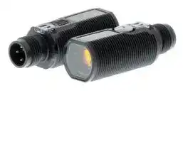


E3F1-TN21
Photoelectric Sensor, 15 m, NPN Open Collector, 100 mA Output, 10 VDC to 30 VDC
- Manufacturer: OMRON INDUSTRIAL AUTOMATION
- Product type:
- SVHC: To Be Advised
- Product Range: E3F1 Series
- Sensing Range Max: 15m
- Sensor Output Type: NPN Open Collector
- Supply Voltage DC Max: 30V
- Supply Voltage DC Min: 10V
| Delivery and price | |
|---|---|
| Units per pack | 1 |
| Price | 70.9 € |
| Current stock | 10+ |
| Lead time | 30 days |
**Photoelectric sensor in compact M18 housing E3F1** - M18 size Photoelectric sensor with best value at competitive price - Bright visible red LED enabling easy alignment - Compact and robust housing for easy integration into machines - Reliable operation in all industrial environments ## **Ordering Information** |**Sensor type**<br>~~—_>~~<br>~~TT~~<br>~~oo~~|**Sensing distance**<br>~~>~~<br>~~TT~~<br>|**Connection method**<br>~~|~~|**Model**<br>~~PT~~|**Model**<br>~~PT~~| |---|---|---|---|---| ||||**NPN output**<br>~~PT~~<br>~~|~~|**PNP output**| |Through-beam<br>~~—_ >~~<br>~~TT~~<br>~~oo ~~<br><br>~~1~~|15 m<br>~~>~~<br>~~TT~~<br> ~~=~~<br><br>~~1~~|pre-wired<br>~~|~~|**E3F1-TN11 2M*1**<br>~~PT~~<br>~~|~~|**E3F1-TP11 2M*1**| |||M12 connector<br>~~|~~<br>~~es~~|**E3F1-TN21*1**<br>~~|~~<br>~~es~~|**E3F1-TP21*1**| |Retro-reflective*2<br> <br>~~ed~~<br>~~1~~|0.1 to 3 m<br>with E39-R1S<br> ~~=~~<br>~~ed ~~<br>~~1~~|pre-wired<br>~~po~~<br>~~es~~|**E3F1-RN11 2M**<br>~~po~~<br>~~es~~|**E3F1-RP11 2M**| |||M12 connector<br>~~po~~<br> ~~es~~|**E3F1-RN21**<br>~~po~~<br>~~es~~|**E3F1-RP21**| |Diffuse-reflective<br><br>~~1~~|100 mm<br> <br>~~1~~|pre-wired<br> ~~es~~|**E3F1-DN11 2M**<br>~~es~~|**E3F1-DP11 2M**| |||M12 connector<br>pre-wired<br> ~~es~~<br>~~tT~~|**E3F1-DN21**<br>**E3F1-DN12 2M**<br>~~es~~<br>~~tT~~|**E3F1-DP21**<br>**E3F1-DP12 2M**| ||300 mm|pre-wired<br>~~—~~|**E3F1-DN12 2M**|**E3F1-DP12 2M**| |||M12 connector<br>~~—~~|**E3F1-DN22**|**E3F1-DP22**| > *2 The Reflector is sold separately. |**Reflectors[Refer to****_Dimensions_on page**|**Reflectors[Refer to****_Dimensions_on page**|**on page** **6****_._]**|||| |---|---|---|---|---|---| |**Reflectors required for Retro-reflective Sensors: A Reflector is not provided with the Sensor. Be sure to order a Reflector separately.**||**Reflectors required for Retro-reflective Sensors: A Reflector is not provided with the Sensor. Be sure to order a Reflector separately.**|||| |**Sensor**|**Sensing distance**|**Appearance**<br>**Model**<br>**Quantity**<br>~~eeee~~|||**Remarks**| |E3F1-R**@**|0.1 to 3 m||**E39-R1S**|1|for E3F1-R**@**| |**Mounting brackets[Refer to****_Dimensions_on page**|||**6****_._]**||| |**A Mounting Bracket is not enclosed with the Sensor. Order a Mounting Bracket separately if required.**|||||| |**Sensor**|**Appearance**<br>~~a~~|**Model (Material)**<br>~~a~~|**Quantity**<br>~~a~~|**Remarks**| |---|---|---|---|---| |all types|Lp|**E39-L183**(SUS304)|1|Mounting bracket| |||**E39-L182**(POM)|1|Flush mounting bracket| **1** **E3F1** ## **Sensor I/O connectors** **Models for Connectors: A Connector is not provided with the Sensor. Be sure to order a Connector separately.** |**Sensor**|**Size**|**Cable**|**Appearance**|**Appearance**|**Appearance**|**Cable type**|**Cable type**|**Model**| |---|---|---|---|---|---|---|---|---| |M12 connector types|M12|Standard|Straight|||2 m|4-wire|**XS2F-M12PVC4S2M-EU**| |||||||5 m||**XS2F-M12PVC4S5M-EU**| ||||Angle|||2 m||**XS2F-M12PVC4A2M-EU**| |||||||5 m||**XS2F-M12PVC4A5M-EU**| ## **Specifications** ||**Sensing method**|**Sensing method**|**Through-beam**|**Retro-reflective**|**Diffuse-reflective**|**Diffuse-reflective**| |---|---|---|---|---|---|---| |**Model**|**NPN**<br>**output**|**Pre-wired**|**E3F1-TN11 2M**|**E3F1-RN11 2M**|**E3F1-DN11 2M**|**E3F1-DN12 2M**| |||**M12 Connector**|**E3F1-TN21**|**E3F1-RN21**|**E3F1-DN21**|**E3F1-DN22**| ||**PNP**<br>**output**|**Pre-wired**|**E3F1-TP11 2M**|**E3F1-RP11 2M**|**E3F1-DP11 2M**|**E3F1-DP12 2M**| |**Item**||**M12 Connector**|**E3F1-TP21**|**E3F1-RP21**|**E3F1-DP21**|**E3F1-DP22**| |**Sensing distance**|||15 m|0.1 to 3 m<br>(with E39-R1S)|100 mm<br>(white paper:<br>300300 mm)|300 mm<br>(white paper:<br>300300 mm)| |**Spot diameter (typical)**|||—|—|4045 mm<br>Sensing distance<br>of 100 mm|4050 mm<br>Sensing distance<br>of 300 mm| |**Directional angle**|||2° min.|2° min.|—|—| |**Light source (wavelength)**|||Red LED (624 nm)|||| |**Power supply voltage**|||10 to 30 VDC (include voltage ripple of 10%(p-p) max.)|||| |**Current consumption**|||40 mA max.<br>(Emitter 25 mA max.<br>Receiver 15 mA max.)|25 mA max.||| |**Control output**|||NPN/PNP (open collector)<br>Load current: 100 mA max. (Residual voltage: 3 V max.), Load power supplyvoltage: 30 VDC max.|||| |**Operation mode**|||Light-ON/Dark-ON selectable bywiring|||| |**Indicator**|||Operation indicator (orange)<br>Stability indicator (green)<br>Power indicator (green): onlyEmitter of Through-beam|||| |**Protection circuits**|||Reversed power supply polarity protection, Output short-circuit protection and Reversed output po-<br>larityprotection|||| |**Response time**|||0.5 ms|||| |**Sensitivity adjustment**|||One-turn adjuster|||| |**Ambient temperature range**|||Operating: -25 to 55°C/ Storage: -30 to 70°C (with no icingor condensation)|||| |**Ambient humidity range**|||Operating: 35 to 85%RH/ Storage: 35 to 95%RH (with no condensation)|||| |**Degree of protection**|||IEC: IP66|||| |**Weight**<br>**(packed**<br>**state/only**<br>**sensor)**|**Pre-wired cable (2M)**||Approx. 110 g/<br>Approx. 50 g,<br>respectively|Approx. 60 g/ Approx. 50 g||| ||**Connector**||Approx. 30 g/<br>Approx. 10 g,<br>respectively|Approx. 20 g/ Approx. 10 g||| |**Material**|**Case**||ABS|||| ||**Lens and Display**||PMMA|||| ||**Adjuster**||POM|||| ||**Nut**||ABS|||| |**Accessories**|||Instruction sheet<br>M18 nuts (4 pcs)|Instruction sheet<br>M18 nuts (2 pcs)||| **2** **E3F1** ## **Output circuit diagram** ## **PNP Output** **==> picture [511 x 494] intentionally omitted <==** **----- Start of picture text -----**<br> Model Operation mode Timing charts Operation selector Output circuit<br>Light incident Through-beam Receivers, Retro-reflective Models,<br>Operation indicator (orange) Light interruptedOFFON Connect the Diffuse-reflective Models<br>Light-ON Output transistor OFFON pink wire Brown 10 to 30 VDC<br>Load(e.g., relay) OperateReset (Between blue (Pin(2)) to the brown (Pin(1)) Operation indicator(Orange) Stabilityindicator(Green) 1 Light-ON 100 mA max.<br>Light incidentand black leads) Connect the Photo-electric Sensor Main 4 BlueBlack (Relay)Load (Control output)<br>E3F1-TPE3F1-RP@@ Dark-ON Operation indicator (orange)Output transistorLight interruptedOFFOFFONON pink wire (Pin(2)) to the blue (Pin(3)) Circuit 32 Pink Dark-ON 0 V<br>E3F1-DP@ Load(e.g., relay) OperateReset (Between blue or open the pink wire<br>and black leads) (Pin(2))<br>Through-beam Emitter<br>Power 1 Brown<br>indicator<br>(green)<br>Photo-<br>electric 10 to 30 VDC<br>Sensor<br>Main<br>Circuit Blue<br>3<br>NPN Output<br>Model Operation mode Timing charts Operation selector Output circuit<br>Light incident Connect the Through-beam Receivers, Retro-reflective Models,<br>Operation indicator Light interruptedON pink wire Diffuse-reflective Models<br>Light-ON (orange)Output transistor OFFOFFON (Pin(2)) to the brown (Pin(1)) Brown 10 to 30 VDC<br>Load(e.g., relay)Light interruptedLight incidentOperateReset(Between brown and black leads) or open the pink wire (Pin(2)) Operation indicator(Orange) Stabilityindicator(Green)Photo-electric Sensor MainCircuit 143 BlackBlue Light-ON (Relay)Load100 mA max.(Control output)<br>Operation indicator ON 0 V<br>E3F1-TNE3F1-RNE3F1-DN@@@ Dark-ON (orange)Output transistorLoad(e.g., relay) OperateResetOFFOFFON Connect the pink wire (Pin(2)) to the blue (Pin(3)) 2 Pink Dark-ON<br>(Between brown<br>and black leads)<br>Through-beam Emitter<br>Power 1 Brown<br>indicator<br>(green)<br>Photo-<br>electric 10 to 30 VDC<br>Sensor<br>Main<br>Circuit Blue<br>3<br>**----- End of picture text -----**<br> ## **Connector Pin Arrangement** **M12 Connector Pin Arrangement** **Connectors (Sensor I/O connectors) M12 4-wire Connectors** **==> picture [30 x 30] intentionally omitted <==** **----- Start of picture text -----**<br> 1<br>2 4<br>3<br>**----- End of picture text -----**<br> |2<br>4<br>1|3<br>1<br>2<br>3<br>4<br>Pin|Brown<br>Blue<br>White<br>Black<br>No.<br>Wire color|Brown<br>Blue<br>White<br>Black<br>No.<br>Wire color|Brown<br>Blue<br>White<br>Black<br>No.<br>Wire color| |---|---|---|---|---| |**Classification**|**Wire color**||**Connector pin No**|**.**<br>**Application**| |DC|Brown||➀|Power supply (+V)| ||White||➁|L/on · D/on selectable| ||Blue||➂|Power supply (0 V)| ||Black||➃|Output| **3** **E3F1** ## **Nomenclature** **==> picture [243 x 145] intentionally omitted <==** **----- Start of picture text -----**<br> Straight<br>with an adjuster:<br>E3F1-T@-D<br>E3F1-R@<br>E3F1-D@<br>without an adjuster:<br>E3F1-T@-L *<br>Sensitivity adjuster<br>ay<br>Stability indicator Operation indicator<br>(Green) (Orange)<br>**----- End of picture text -----**<br> * The Emitter has two Power indicators (Green) instead of the Stability indicator (Green) and the Operation indicator (Orange). ## **Safety Precautions** ## **Refer to** _**Warranty and Limitations of Liability**_ **.** ## **WARNING** **This product is not designed or rated for directly or indirectly ensuring safety of persons. Do not use it for such a purpose.** ## **Precautions for Safe Use** ~~Po~~ Be sure to follow the safety precautions below for added safety. 1. Do not use the sensor under the environment with explosive, flammable or corrosive gas. 2. Do not use the sensor under the oil or chemical environment. ## **CAUTION** **Never use the product with an AC power supply. Do not use the product with voltage in excess of the rated voltage.** 3. Do not use the sensor in the water, rain or outdoors. 4. Do not use the sensor in the environment where humidity is high and condensation may occur. 5. Do not use the sensor under the environment under the other conditions in excess of rated. 6. Do not use the sensor in place that is exposed by direct sunlight. **Do not use the product with incorrect wiring. Otherwise, explosion, fire, malfunction may result.** 7. Do not use the sensor in place where the sensor may receive direct vibration or shock. 8. Do not use the thinner, alcohol, or other organic solvents. 9. Never disassemble, repair nor tamper with the sensor. 10.Please process it as industrial waste. - **Precautions for Correct Use** - ~~DP~~ 1. Laying Sensor wiring in the same conduit or duct as high-voltage wires or power lines may result in malfunction or damage due to conduit or use shielded cable. 2. Do not pull on the cable with excessive force. 3. If a commercial switching regulator is used, ground the FG (frame ground) terminal. 4. The sensor will be available 100 ms after the power supply is tuned ON. Start to use the sensor 100 ms or more after turning ON the power supply. If the load and the sensor are connected to separate power supplies, be sure to turn ON the sensor first. 5. Output pulses may be generated even when the power supply is OFF. Therefore, it is recommended to first turn OFF the power supply for the load or the load line. 6. The sensor must be mounted using the provided nuts. The proper tightening torque range is between 0.4 and 0.5 N·m. **4** **E3F1** (Unit: mm) ## **Dimensions** Tolerance class IT16 applies to dimensions in this data sheet unless otherwise specified. ## **Sensors** **==> picture [510 x 371] intentionally omitted <==** **----- Start of picture text -----**<br> Pre-wired Models Front view<br>E3F1-T@ 41 Sensitivity adjuster *<br>E3F1-R@ Left side view Left side view 2 34.5 7 dia. Operation indicator (orenge) Mounting Holes<br>E3F1-D@ 15 15 Receiver M18 × 30.5 P=1 Sensitivity indicator (green) 18.5 dia.+0.5 0<br>7 16.6 dia.<br>Emitter 23 Vinyl insurated round cord 4 dia. 4 cores<br>Optical axis Optical axis 30.5 (conductor cross sectional area:0.128 mm/insulation outside diameter:0.85 dia.) [2] (AWG26)<br>Suitable models Suitable models * Suitable models standard length 2 m<br>E3F1-T@11 E3F1-R@11 E3F1-T@11-D<br>E3F1-D@1@ E3F1-R@12<br>E3F1-D@1@<br>M12 Connector Models Front view Right side view<br>E3F1-T@ 45 Sensitivity adjuster *<br>E3F1-R@ Left side view Left side view 2 34.5 7 dia. Operation indicator (orenge) Mounting Holes<br>E3F1-D@ 15 15 Receiver M18 × 30.5 P=1 Sensitivity indicator (green) 18.5 dia.+0.5 0<br>2 1<br>7 16.6 dia.<br>Emitter M12 × 4 P=1 3 4<br>23<br>6 Optical axis O Optical axis me 30.5 o<br>Suitable models Suitable models * Suitable models<br>Terminal No. Specification<br>E3F1-T@21 E3F1-R@21 E3F1-T@21-D<br>1 +V<br>E3F1-D@2@ E3F1-R@22<br>2 L/on · D/on selectable<br>E3F1-D@2@<br>3 0V<br>4 Output<br>Attached nut<br>8<br>24 dia.<br>Three, 22<br>M18 × 7.5 P=1<br>**----- End of picture text -----**<br> ## **Attached nut** **5** **E3F1** ## **Accessories (Order Separately)** ## **Reflectors** **E39-R1S** **==> picture [143 x 108] intentionally omitted <==** **----- Start of picture text -----**<br> 40.3<br>Two, 3.5 dia. 34 7.5<br>7<br>59.9 52<br>8<br>1.6 2.7<br>**----- End of picture text -----**<br> **Mounting brackets E39-L183** **==> picture [255 x 166] intentionally omitted <==** **----- Start of picture text -----**<br> 42<br>4.3<br>Two, R15<br>16<br>Two, 30°<br>37 Two, 4.3<br>23<br>1.5<br>(R16.5)<br>90°<br>18.2 dia.<br>36.5<br>20<br>**----- End of picture text -----**<br> **Mounting brackets E39-L182** **==> picture [171 x 150] intentionally omitted <==** **----- Start of picture text -----**<br> 14.5 12.5<br>27 dia.<br>15.1<br>16.7 dia.<br>**----- End of picture text -----**<br> **6** **E3F1** **7** ## **Read and Understand This Catalog** Please read and understand this catalog before purchasing the products. Please consult your OMRON representative if you have any questions or comments. ## **Warranty and Limitations of Liability** ## **WARRANTY** OMRON's exclusive warranty is that the products are free from defects in materials and workmanship for a period of one year (or other period if specified) from date of sale by OMRON. OMRON MAKES NO WARRANTY OR REPRESENTATION, EXPRESS OR IMPLIED, REGARDING NON-INFRINGEMENT, MERCHANTABILITY, OR FITNESS FOR PARTICULAR PURPOSE OF THE PRODUCTS. ANY BUYER OR USER ACKNOWLEDGES THAT THE BUYER OR USER ALONE HAS DETERMINED THAT THE PRODUCTS WILL SUITABLY MEET THE REQUIREMENTS OF THEIR INTENDED USE. OMRON DISCLAIMS ALL OTHER WARRANTIES, EXPRESS OR IMPLIED. ## **LIMITATIONS OF LIABILITY** OMRON SHALL NOT BE RESPONSIBLE FOR SPECIAL, INDIRECT, OR CONSEQUENTIAL DAMAGES, LOSS OF PROFITS OR COMMERCIAL LOSS IN ANY WAY CONNECTED WITH THE PRODUCTS, WHETHER SUCH CLAIM IS BASED ON CONTRACT, WARRANTY, NEGLIGENCE, OR STRICT LIABILITY. In no event shall the responsibility of OMRON for any act exceed the individual price of the product on which liability is asserted. IN NO EVENT SHALL OMRON BE RESPONSIBLE FOR WARRANTY, REPAIR, OR OTHER CLAIMS REGARDING THE PRODUCTS UNLESS OMRON'S ANALYSIS CONFIRMS THAT THE PRODUCTS WERE PROPERLY HANDLED, STORED, INSTALLED, AND MAINTAINED AND NOT SUBJECT TO CONTAMINATION, ABUSE, MISUSE, OR INAPPROPRIATE MODIFICATION OR REPAIR. ## **Application Considerations** ## **SUITABILITY FOR USE** OMRON shall not be responsible for conformity with any standards, codes, or regulations that apply to the combination of products in the customer's application or use of the products. At the customer's request, OMRON will provide applicable third party certification documents identifying ratings and limitations of use that apply to the products. This information by itself is not sufficient for a complete determination of the suitability of the products in combination with the end product, machine, system, or other application or use. The following are some examples of applications for which particular attention must be given. This is not intended to be an exhaustive list of all possible uses of the products, nor is it intended to imply that the uses listed may be suitable for the products: - Outdoor use, uses involving potential chemical contamination or electrical interference, or conditions or uses not described in this catalog. - Nuclear energy control systems, combustion systems, railroad systems, aviation systems, medical equipment, amusement machines, vehicles, safety equipment, and installations subject to separate industry or government regulations. - Systems, machines, and equipment that could present a risk to life or property. Please know and observe all prohibitions of use applicable to the products. NEVER USE THE PRODUCTS FOR AN APPLICATION INVOLVING SERIOUS RISK TO LIFE OR PROPERTY WITHOUT ENSURING THAT THE SYSTEM AS A WHOLE HAS BEEN DESIGNED TO ADDRESS THE RISKS, AND THAT THE OMRON PRODUCTS ARE PROPERLY RATED AND INSTALLED FOR THE INTENDED USE WITHIN THE OVERALL EQUIPMENT OR SYSTEM. ## **PROGRAMMABLE PRODUCTS** OMRON shall not be responsible for the user's programming of a programmable product, or any consequence thereof. ## **Disclaimers** ## **CHANGE IN SPECIFICATIONS** Product specifications and accessories may be changed at any time based on improvements and other reasons. It is our practice to change model numbers when published ratings or features are changed, or when significant construction changes are made. However, some specifications of the products may be changed without any notice. When in doubt, special model numbers may be assigned to fix or establish key specifications for your application on your request. Please consult with your OMRON representative at any time to confirm actual specifications of purchased products. ## **DIMENSIONS AND WEIGHTS** Dimensions and weights are nominal and are not to be used for manufacturing purposes, even when tolerances are shown. ## **PERFORMANCE DATA** Performance data given in this catalog is provided as a guide for the user in determining suitability and does not constitute a warranty. It may represent the result of OMRON’s test conditions, and the users must correlate it to actual application requirements. Actual performance is subject to the OMRON Warranty and Limitations of Liability. ## **ERRORS AND OMISSIONS** The information in this document has been carefully checked and is believed to be accurate; however, no responsibility is assumed for clerical, typographical, or proofreading errors, or omissions. Cat. No. E94E-EN-01 **In the interest of product improvement, specifications are subject to change without notice.** ## **OMRON EUROPE B.V.** Wegalaan 67-69, NL-2132 JD, Hoofddorp, The Netherlands Phone: +31 23 568 13 00 Fax: +31 23 568 13 88 www.industrial.omron.eu
Updated at April 23, 2026
With a legacy spanning over 80 years, Omron Industrial Automation is a globally recognized leader in the manufacture of advanced industrial control and automation components. Renowned for their reliability and engineering excellence, Omron delivers comprehensive solutions that enhance efficiency, machine safety, and precision across a wide range of manufacturing environments. Our extensive portfolio of Omron products is heavily focused on their industry-leading sensing and switching technologies. We offer a vast selection of sensors, excelling specifically in high-performance proximity sensors, light sensors, and temperature sensors. Complementing this range are robust switching solutions, featuring a deep inventory of power relays, solid-state relays, safety relays, and essential relay accessories designed for demanding operational requirements. Beyond sensing and switching, Omron is highly regarded for its precision automation and process control equipment. Our selection features highly accurate temperature controllers, versatile process controllers, and sophisticated panel displays and instrumentation. To support these fundamental systems, we also supply dependable Omron power supplies, notably AC/DC converters, alongside vital connectivity components like DIN rail terminal blocks to ensure secure, efficient, and complete industrial setups.
About Novapart
Novapart is a B2B electronic component broker specialising in stock shortages and cost reduction. We source hard-to-find parts and identify compliant alternatives across a catalogue of 410,000+ components from 500+ manufacturers.
Learn more →Stock Shortage Specialist
When a component is unavailable, discontinued or has an unacceptable lead time, we tap into our network of vetted European and Asian distributors to source what you need — without compromising on quality or traceability.
Request a quote →Compliant Alternatives
We identify pin-to-pin, electrically equivalent substitutes that meet the same certifications (RoHS, AEC-Q100, REACH) as your original specification — validated against datasheets, not just part numbers. Often at a lower cost.
BOM Analysis service →