
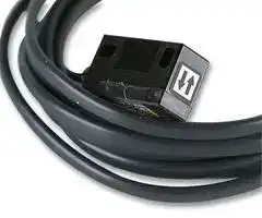


E3C-1
PHOTOELECTRIC SENSOR, 1M, IP66
- Manufacturer: OMRON INDUSTRIAL AUTOMATION
- Product type:
- Sensing; PHOTOELECTRIC SENSOR, 1M, IP66; Sensing Range Max:1m; Sensing Method:Pulse modulated infrared LED; Sensor Output Type:-; Product Range:-; Connection Method:Cable; Supply Voltage D
- Product Range: -
- Sensing Method: Pulse modulated infrared LED
- Connection Method: Cable
- Sensing Range Max: 1m
- Sensor Output Type: -
- Supply Voltage Max: -
- Supply Voltage Min: -
- Sensing Distance Max: 1m
- Supply Voltage DC Max: -
- Supply Voltage DC Min: -
| Delivery and price | |
|---|---|
| Units per pack | 25 |
| Price | 85.27 € |
| Current stock | 10+ |
| Lead time | 30 days |
**Compact Head Amplifier-separated Photoelectric Sensor E3C**

CSM_E3C_DS_E_11_2

## **Thin, Compact Head Saves Space and Mounts Closely. Built-in Interference Protection Provided.**

- Input indicator on the Sensor Unit simplifies settings.

Be sure to read _Safety Precautions_ on page 8. ~~a~~

## **Ordering Information**

## **Sensors**

**Sensor Units [Refer to** _**Dimensions**_ **on page 9.]**

**==> picture [497 x 318] intentionally omitted <==**

**----- Start of picture text -----**<br>
[Refer to  Dimensions  on page 9.] Red light Infrared light<br>Sensing method a Application Appearance Sensing distance Model<br>10 es E3C-S10 2M  2 * 1 :<br>100 mm Emitter E3C-S10L 2M<br>12 11 Receiver E3C-S10D 2M<br>5.8 — E3C-S50 2M * 1  * 2<br>13<br>500 mm Emitter E3C-S50L 2M<br>25 7 — Receiver E3C-S50D 2M<br>Small type LD = =aI E3C-1 2M * 1<br>12 1 m Emitter E3C-1L 2M<br>iw 8 36 =m Receiver E3C-1D 2M<br>(Emitter + Receiver)Through-beam 18 16 = 2 m E3C-2 2M  Emitter E3C-2L 2M * 1<br>12.4 Receiver E3C-2D 2M<br>12.5<br>15 200 mm E3C-S20W 2M<br>2.8<br>Slim type<br>3 7.85 8 E3C-S30W 2M<br>eS 3 a<br>oe ei. 15 300 mm<br>Side-view E3C-S30T 2M<br>15<br>1 Fic2—<br>Small type 18 26 100 mm E3C-DS10 2M<br>10<br>Diffuse-reflective Slim type 19.52.8 11 50 mm E3C-DS5W 2M<br>| # =a<br>21<br>Side-view 18 100 mm E3C-DS10T 2M<br>8<br>@ aHy<br>36<br>Convergent-reflective Small type 30±3 mm E3C-LS3R 2M<br>10<br>**----- End of picture text -----**<br>


- *1. Through-beam Sensors are normally sold in sets that include both the Emitter and Receiver.

- *2. You cannot order the Emitter and Receiver with separate model numbers. Always order them together using the model number for the set (E3C-S50 2M).

**1**

**E3C**

**Amplifier Units [Refer to** _**Amplifier Units**_ **on page 12.]**

|**Power supply**|**Application**|**Appearance**|**Functions**|**Model**|
|---|---|---|---|---|
|DC|Slim type|60<br>30<br>14|Self<br>diagnostic|**E3C-JC4P 2M**|


## **Accessories (Order Separately)**

**Mounting Brackets [Refer to** _**E39-L/E39-S/E39-R**_ **for Dimensions.** ]

|**Appearance**|**Model**|**Quantity**|**Remarks**|
|---|---|---|---|
||**E39-L41**|2|Provided with the E3C-1.|
||**E39-L42**|2|Provided with the E3C-2.<br>Can be used with the E3C-DS10.|
||**E39-L127-T1**|1|Can be used with the E3C-S10.|
||**E39-L127-T2**|1||
||**E39-L127-T3**|1||
||**E39-L31**|1*|Can be used with the E3C-S50.|


Note: Refer to _E39-L/E39-S/E39-R_ for Dimensions.

- When using through-beam models, order one bracket for the Receiver and one for the Emitter.

**2**

**E3C**

## **Ratings and Specifications**

## **Sensors**

|**Sensing method**|**Sensing method**|**Through-beam**|**Through-beam**|**Through-beam**|**Through-beam**|**Through-beam**|**Through-beam**|**Through-beam**|**Through-beam**|
|---|---|---|---|---|---|---|---|---|---|
|**Item**<br>**Model**||**E3C-S10**|**E3C-S20W**||**E3C-S50**|**E3C-S30T**<br>**E3C-S30W**|**E3C-1**||**E3C-2**|
|**Sensing distance**||100 mm|200 mm||500 mm|300 mm|1 m||2 m|
|**Standard sensing**<br>**object**||Opaque, 2-mm dia. min.|||Opaque, 3-mm<br>dia. min.|Opaque, 1.5-mm<br>dia. min.|Opaque, 4-mm<br>dia. min.||Opaque, 8-mm<br>dia. min.|
|**Directional angle**||Emitter/Receiver: 10 to 60°each|||Emitter/Receiver: 10 to 40°each||Emitter/Receiv-<br>er: 3 to 20°each||Emitter/Receiv-<br>er: 3 to 15°each|
|**Light source (wavelength)**||Infrared LED (950 nm)||||Infrared LED<br>(940 nm)|Infrared LED (950 nm)|||
|**Ambient illuminance**<br>**(Receiver side)**||Incandescent lamp: 3,000 lx max., Sunlight 10,000 lx max.||||||||
|**Ambient temperature range**||Operating/Storage:−25 to 70°C (with no icing or condensation)||||||||
|**Ambient humidity range**||Operating/Storage: 35% to 85%RH (with no condensation)||||||||
|**Insulation resistance**||20 MΩmin. at 500 VDC||||||||
|**Dielectric strength**||500 VAC at 50/60 Hz for 1 minute||||||||
|**Vibration resistance**||Destruction: 10 to 55 Hz, 1.5-mm double amplitude for 2 hours each in X, Y, and Z directions||||||||
|**Shock resistance**||Destruction: 500 m/s2for 3 times each in X, Y, and Z directions||||||||
|**Degree of protection**||IEC 60529 IP64<br>Limited to indoor<br>use|IEC 60529 IP50<br>Limited to indoor<br>use||IEC 60529 IP64<br>Limited to indoor<br>use|IEC 60529 IP60<br>Limited to indoor<br>use|IEC 60529 IP66<br>Limited to indoor use|||
|**Connection method**||Pre-wired models (standard length: 2 m)||||||||
|**Weight (packed state)**||Approx. 50 g||||Approx. 24 g|Approx. 60 g||Approx. 120 g|
|**Material**|**Case**|Polycarbonate|||ABS|Polycarbonate|||Zinc die-cast|
||**Lens**|Polycarbonate|||Acrylics|Polycarbonate||||
||**Mounting**<br>**Brackets**|---|||||Steel|||
|**Accessories**||Instruction<br>manual|Phillips screw<br>M2×8, spring<br>washer, flat<br>washer, M2 nut,<br>instruction<br>manual||Instruction<br>manual|Phillips screw<br>M2×8, spring<br>washer, flat<br>washer, nut M2,<br>instruction<br>manual|Mounting<br>Bracket (with<br>screws),<br>instruction<br>manual||Mounting<br>Bracket (with<br>screws),<br>instruction<br>manual|
|||||||||||
|**Sensing method**||**Diffuse-reflective**||||||**Convergent-reflective**||
|**Item**<br>**Model**||**E3C-DS5W**||**E3C-DS10T**||**E3C-DS10**||**E3C-LS3R**||
|**Sensing distance**||50 mm (White paper 100×<br>100 mm)||100 mm (White paper 100<br>×100 mm)||100 mm (White paper 50×<br>50 mm)||30±3 mm (White paper 10<br>×10 mm)||
|**Differential travel**||20% max. of sensing distance||||10% max.||±3% max.||
|**Light source (wavelength)**||Infrared LED (950 nm)||Infrared LED (950 nm)||||Red LED (680 nm)||
|**Ambient illuminance**<br>**(Receiver side)**||Incandescent lamp: 3,000 lx max., Sunlight 10,000 lx max.||||||||
|**Ambient temperature range**||Operating/Storage:−25 to 70°C (with no icing or condensation)||||||||
|**Ambient humidity range**||Operating/Storage: 35% to 85%RH (with no condensation)||||||||
|**Insulation resistance**||20 MΩmin. at 500 VDC||||||||
|**Dielectric strength**||500 VAC at 50/60 Hz for 1 minute||||||||
|**Vibration resistance**||Destruction: 10 to 55 Hz, 1.5-mm double amplitude for 2 hours each in X, Y, and Z directions||||||||
|**Shock resistance**||Destruction: 500 m/s2for 3 times each in X, Y, and Z directions||||||||
|**Degree of protection**||IEC 60529 IP50 (Limited to indoor use)||||IEC 60529 IP64 (Limited to indoor use)||||
|**Connection method**||Pre-wired models (standard length: 2 m)||||||||
|**Weight (packed state)**||Approx. 50 g||||||Approx. 55 g||
|**Material**|**Case**|Polycarbonate||||||||
||**Lens**|Polycarbonate||||||||
|**Accessories**||Phillips screw M2×8,<br>spring washer, flat washer,<br>M2 nut, instruction manual||Instruction manual||||||


**3**

**E3C**

## **Amplifier Units**

|**Item**<br>**Model**|**Item**<br>**Model**|**E3C-JC4P**|
|---|---|---|
|**Power supply**<br>**voltage**||12 to 24 VDC±10%, ripple (p-p): 1 V max.|
|**Power (current)**<br>**consumption**||40 mA max.|
|**Control output**||Load power supply voltage: 24 VDC max., load current: 100 mA max., NPN open collector output type (residual voltage:<br>1 V max.)<br>Light-ON/Dark-ON switch selectable|
|**Timer function**||OFF-delay 0/40 ms (switch selectable)|
|**Ambient temperature range**||Operating:−10°to 55°C, Storage:−25°to 70°C (with no icing or condensation)|
|**Ambient humidity range**||Operating: 35% to 85%, Storage: 35% to 85% (with no condensation)|
|**Insulation resistance**||20 MΩmin. at 500 VDC|
|**Dielectric strength**||1,000 VAC at 50/60 Hz for 1 minute|
|**Vibration resistance**||Destruction: 10 to 55 Hz, 1.5-mm double amplitude for 2 hours each in X, Y, and Z directions|
|**Shock resistance**||Destruction: 300 ms2three times in each of X, Y and Z directions|
|**Degree of protection**||IEC IP40 (limited to indoor use)|
|**Protection**||Reverse polarity protection, output short-circuit protection, mutual interference prevention|
|**Response time**||Operate or reset: 1 ms max.|
|**Connection method**||Terminal block input cable pullout (standard cable length: 2 m)|
|**Weight**<br>**(packed state)**||Approx. 80 g|
|**Material**|**Case**|ABS|
||**Mounting Brackets**|Iron|
|**Accessories**||Mounting Bracket,  Adjustment screwdriver, Caution label, Instruction manual|


**4**

**E3C**

**Engineering Data (Reference Value)**

## **Parallel Operating Range**

**==> picture [509 x 344] intentionally omitted <==**

**----- Start of picture text -----**<br>
Through-beam Through-beam Through-beam<br>E3C-S10 E3C-S20W E3C-S50<br>200 200 200<br>150 Y 150 Y 150 Y<br>100 X 100 X 100 X<br>50 50 50<br>0 50 100 150 200 250 300 0 50 100 150 200 250 300 0 0.2 0.4 0.6 0.8 1<br>Sensing<br>−50 distance X (mm) −50 distance X (mm) Sensing  −50 distance X (mm) Sensing<br>−100 −100 −100<br>−150 −150 −150<br>−200 −200 −200<br>Through-beam Through-beam Through-beam<br>E3C-1 E3C-2 E3C-S30T/-S30W<br>200 200 200<br>150 Y 150 150 Y<br>X X<br>100 100 100<br>Y<br>50 50 50<br>X<br>0 0.5 1 1.5 2 0 1 2 3 4 0 200 400 600 800<br>−50 distance X (mm) Sensing  −50 distance X (mm) Sensing  −50 distance  Sensing<br>X (mm)<br>−100 −100 −100<br>−150 −150 −150<br>−200 −200 −200<br>Operating position Y (mm) Operating position Y (mm) Operating position Y (mm)<br>Operating position Y (mm) Operating position Y (mm) Operating position Y (mm)<br>**----- End of picture text -----**<br>


**==> picture [73 x 9] intentionally omitted <==**

**----- Start of picture text -----**<br>
Operating Range<br>**----- End of picture text -----**<br>


## **Diffuse-reflective**

## **Diffuse-reflective**

## **Diffuse-reflective**

**==> picture [510 x 154] intentionally omitted <==**

**----- Start of picture text -----**<br>
E3C-DS5W E3C-DS10T E3C-DS10 (Example 1)<br>4030 Y X Moving direction of object 4030 Y 4030 ONOFF X Y Moving<br>X direction<br>20 20 20 Optical   of object<br>axis<br>10 10 10<br>0 20 40 60 80 100 120 0 20 40 60 80 100 120 140 160 0 40 80 120 200<br>Sensing  160<br>−10 distance  X (mm) −10 distance Sensing X (mm) −10 distance Sensing<br>−20 −20 −20 X (mm)<br>−30 −30 −30<br>−40 −40 −40<br>Operating position Y (mm) Operating position Y (mm) Operating position Y (mm)<br>**----- End of picture text -----**<br>


**5**

**E3C**

## **Diffuse-reflective**

## **Convergent-reflective**

## **Convergent-reflective**

**==> picture [512 x 522] intentionally omitted <==**

**----- Start of picture text -----**<br>
E3C-DS10 (Example 2) E3C-LS3R (Example 1) E3C-LS3R (Example 2)<br>40 ON X Moving direction  2 ON X Moving direction  2 ON X<br>OFF of object OFF of object OFF<br>30 Y Y Y<br>20 Oaxisptical   1 Optical  axis 1 Optical   axis Moving  direction  of object<br>10<br>0 0 0<br>40 80 120 200 22 26 28 30 32 34 36 38 22 26 28 30 32 34 36 38<br>160 Sensing distance  Sensing distance<br>−10 24 X (mm) 24 X (mm)<br>Sensing<br>−20 distance X (mm) −1 −1<br>−30<br>−40 −2 −2<br>Excess Gain vs. Set Distance<br>E3C-S20W E3C-S30T/-S30W E3C-S50<br>100 100 100<br>70 70 70<br>50 50 50<br>30 30 30<br>10 10 10<br>7 7 7<br>5 5 5<br>3 3 3<br>1 Operating Level 1 Operating Level 1 Operating Level<br>0.7 0.7 0.7<br>0.5 0.5 0.5<br>0.3 0.3 0.3<br>0.1 0.1 0.1<br>0 100 200 300 400 500 0 0.2 0.4 0.6 0.8 1 0 0.2 0.4 0.6 0.8 1<br>Set distance (mm) Set distance (mm) Set distance (mm)<br>E3C-DS5W E3C-DS10T E3C-LS3R<br>100 100 100<br>70 70 70<br>50 50 50<br>30 30 30<br>10 10 10<br>7 7 7<br>5 5 5<br>3 3 3<br>1 Operating Level 1 Operating Level 1 Operating Level<br>0.7 0.7 0.7<br>0.5 0.5 0.5<br>0.3 0.3 0.3<br>0.1 0.1 0.1<br>0 50 100 150 200 0 50 100 150 200 0 10 20 30 40 50<br>Set distance (mm) Set distance (mm) Set distance (mm)<br>Operating position Y (mm) Operating position Y (mm) Operating position Y (mm)<br>Excess Gain ratio<br>Excess Gain ratio Excess Gain ratio<br>Excess Gain ratio Excess Gain ratio<br>Excess Gain ratio<br>**----- End of picture text -----**<br>


**6**

**E3C**

## **I/O Circuit Diagrams**

## **NPN output**

**==> picture [510 x 129] intentionally omitted <==**

**----- Start of picture text -----**<br>
Model Operation  Timing charts Operation  Output circuit<br>mode selector<br>Incident light<br>No incident light<br>Light ON Brown12 to 24 VDC<br>Light-ON indicator(red)Output OFFON (LIGHT ON)L-ON Lightindicator Stabilityindicator Load 100 mA max.<br>E3C-JC4P transistorLoad(relay etc.)Incident lightOFFOFFON 40 ms (red) (green)Photo-electricSensorMain Z0 BlackBlueOutput 0 V<br>No incident light Circuit<br>Light ON Z1<br>Dark-ON indicator(red)Outputtransistor OFFOFFON (DARK ON)D-ON OrangeSelf diagnostic output<br>Load ON 40 ms 50 mA max.<br>(relay etc.) OFF<br>**----- End of picture text -----**<br>


## **Connection**

**==> picture [512 x 157] intentionally omitted <==**

**----- Start of picture text -----**<br>
Amplifier Units Connected to the through-beam model Connected to the reflective model Note<br>Emitter Receiver Emitter/receiver<br>Note: 1. The strip-off length of the<br>shielded cable should<br>E3C-JC4P Shield White Shield White always be 20 mm max. on<br>Red Shield Red Shield the Receiver side (white)<br>and 50 mm max. on the<br>Emitter side (red).<br>**----- End of picture text -----**<br>


## **Nomenclature/Settings**

**==> picture [511 x 180] intentionally omitted <==**

**----- Start of picture text -----**<br>
Amplifier Units Nomenclature<br>Stability indicator  Light indicator<br>E3C-JC4P<br>(green) (red)<br>Sensitivity adjuster<br>(4-turn endless asjuster)<br>Operation selector<br>**----- End of picture text -----**<br>


**7**

**E3C**

## **Safety Precautions**

## **Refer to** _**Warranty and Limitations of Liability**_ **.**

## **WARNING**

**This product is not designed or rated for ensuring safety of persons either directly or indirectly. Do not use it for such purposes.**

## **Precautions for Correct Use**

Do not use the product in atmospheres or environments that exceed product ratings.

## **Amplifier Units**

## ● **Wiring**

## **Connection of Amplifier Unit and Sensor**

Always run the shielded wires of the Emitter and Receiver separately. Also, route the sensor cable along the cable grooves of the cover and sensor and fix it with the cover.

**==> picture [101 x 44] intentionally omitted <==**

**----- Start of picture text -----**<br>
White (Shield)<br>Receiver<br>Emitter<br>(Shield) Red<br>**----- End of picture text -----**<br>


## **Sensor Units**

## ● **Wiring**

## **Extension Cable**

- The extension distance of the sensor connection cable should be within 10 m including sensor cable.

- The strip-off length of the core in the connection cable should be 20 mm max. on the Receiver side and 50 mm max. on the Emitter side, and the core should be as short as possible. Avoid using the joint terminal and connector.

**==> picture [88 x 55] intentionally omitted <==**

**----- Start of picture text -----**<br>
Socket<br>20 mm max.<br>**----- End of picture text -----**<br>


- Use independent shielded wires for the Emitter and Receiver. Using a common shielded wire can cause a malfunction.

## **Extension Cable**

## **Through-beam**

**==> picture [244 x 238] intentionally omitted <==**

**----- Start of picture text -----**<br>
Cable Replacement<br>Model Specified cable cable<br>1-conductor shield/<br>Polyethylene insulation shield<br>Round cable vinyl wire, conduc-<br>tor cross section:<br>E3C-S10 Shield 0.3 mm [2]  min.<br>E3C-1E3C-2 White (polyethylene) Shield<br>2.4 dia.<br>E3C-S50 White<br>(vinyl)<br>12-conductor, 0.18 dia.<br> Gray (vinyl sheath)<br>Vinyl insulation shield round cable<br>Sheath<br>Shield<br>E3C-S20W 1.7 dia.<br>Polyethylene<br>Conductor<br>1-conductor shield/<br>12-conductor, 0.18 dia.<br>vinyl wire, conduc-<br>Vinyl insulation shield round cable  tor cross section:<br>(robot cable) 0.3 mm [2]  min.<br>Sheath<br>E3C-S30T<br>E3C-S30W 1.8 dia. Shield<br>Polyethylene<br>Conductor<br>30-conductor, 0.08 dia.<br>**----- End of picture text -----**<br>


## **Reflective model**

**==> picture [244 x 175] intentionally omitted <==**

**----- Start of picture text -----**<br>
Cable Replacement<br>Model Specified cable cable<br>Vinyl insulation shielded parallel ca-<br>ble<br>When there is no1-<br>E3C-DS10 Sheath conductor shielded,<br>E3C-DS10TE3C-VS1G Internal sheath vinyl cable (parallel<br>E3C-VS3R 2.4 Shield wire), use two 1-<br>conductor shielded,<br>E3C-LS3R Polyethylene vinyl wires.<br>4.3 Conductor<br>12-conductor, 0.18 dia.<br>Vinyl insulation shielded parallel ca-<br>ble When there is no1-<br>E3C-DS5W Sheath conductor shielded,<br>E3C-VS7R Shield vinyl cable (parallel<br>E3C-VM35R Polyethylene wire), use two 1-conductor shielded,<br>Conductor vinyl wires.<br>7-conductor, 0.18 dia.<br>**----- End of picture text -----**<br>


## ● **Others**

When the E3C is used in a place where high-frequency noise will be generated, e.g. ultrasonic welder, grounding the 0-V terminal (on the shield side of the connection cable) of the Receiver may avoid a malfunction caused by induction.

**8**

**E3C**

(Unit: mm) Tolerance class IT16 applies to dimensions in this data sheet unless otherwise specified.

## **Dimensions**

## **Sensors**

## **Sensor Units**

## **E3C-S10**

**==> picture [512 x 238] intentionally omitted <==**

**----- Start of picture text -----**<br>
10<br>5.8 Two, 2.9 dia. 2.3 Light indicator (red)<br>(emitter only)<br>12 7.5 2.8<br>2 Emitter/<br>receiver surface<br>2.8<br>5.2 dia.<br>2.4-dia. shielded cable with 1 conductor<br>(Conductor cross section: 0.3 mm [2] ),<br>Emitter: E3C-S10L<br>Standard length: 2 m<br>Receiver: E3C-S10D<br>E3C-S50<br>Emitter/receiver label 11 Light indicator (red)(emitter only)<br>7 2.9 [±][0.2]<br>3.5<br>13 8 [±][0.2]<br>5.7 dia.<br>Emitter/receiver<br>surface Two, 3.2 dia.<br>2.4-dia. shielded cable with 1 conductor<br>(Conductor cross section: 0.3 mm [2] ),<br>Emitter: E3C-S50L Standard length: 2 m<br>Receiver: E3C-S50D<br>**----- End of picture text -----**<br>


## **E3C-1**

**==> picture [512 x 357] intentionally omitted <==**

**----- Start of picture text -----**<br>
25<br>13<br>3 10 2<br>8 6.4 6 dia.<br>3.2<br>8<br>12<br>5.5<br>5<br>3.2<br>4 M3 Light indicator (red)(emitter only) 12 13.5 Iron 2.4-dia. shielded cable with 1 conductor<br>Emitter/receiver (Conductor cross section: 0.3 mm [2] ), Standard length: 2 m<br>6 surface<br>12 5<br>16.5<br>12.5<br>3.5<br>Optical axis position<br>Emitter: E3C-1L Lens 4 dia.<br>Receiver: E3C-1D (A)* * Mounting Bracket can be attached to side A.<br>E3C-2 36 2<br>12.4 9.4 8 dia.<br>3.2<br>8<br>12<br>5.5<br>3.2 4.5<br>M3 Light indicator (red) 23 Iron<br>(emitter only) 2.4-dia. shielded cable with 1 conductor<br>(conductor cross section: 0.3 mm [2] ), Standard length: 2 m<br>Emitter/receiver<br>7 surface<br>16 21<br>17<br>6.7<br>Optical<br>3.3 axis position<br>Lens 8 dia.<br>Emitter: E3C-2L (A)* 13.3 20<br>* Mounting Bracket can be attached to side A.<br>Receiver: E3C-2D<br>**----- End of picture text -----**<br>


**9**

**E3C**

## **E3C-S20W**

**==> picture [512 x 417] intentionally omitted <==**

**----- Start of picture text -----**<br>
Receiver Emitter<br>2,000 2 18 4.5 2 dia. (receiver) 3.6<br>(white) 4.5 Light indicator (red) (Red)<br>4<br>5<br>(6) 12.5<br>1.75-dia. shielded cable  2.5<br>with 1 conductor(Conductor cross section:  11 [±][0.2] 2 dia. (emitter)<br>0.3 mm [2] ),  3.5<br>Standard length: 2 m 3.8 dia.<br>Emitter: E3C-S20LW<br>Receiver: E3C-S20DW 2.3 dia. 1.4 2.8<br>E3C-S30W Receiver Emitter<br>1.5 dia. (receiver)15 5 Light indicator (red) 1.2 dia. 2.45 1.5 dia. (emitter)<br>4 2<br>8<br>1.93-dia. shielded robotics 2.2<br>cable with 1 conductor 7.5<br>(Conductor cross section:0.15 mm [2] ), 2.2 dia. 12 3.6 dia.<br>Standard length: 2 m<br>1 .5 3<br>Emitter: E3C-S30LW<br>Receiver: E3C-S30DW<br>E3C-S30T Receiver Emitter<br>5<br>5<br>1.5 dia. (receiver) 2.4<br>15 Light indicator 1.5 dia. (emitter)<br>(red) 1.2 dia.<br>3.85<br>7.85<br>2.2<br>1.93-dia. shielded robotics<br>cable with 1 conductor 7.5<br>(Conductor cross section: 2.2  12 3.6 dia.<br>0.15 mm [2] ), dia.<br>Emitter: E3C-S30LT Standard length: 2 m 1 .5 3<br>Receiver: E3C-S30DT<br>**----- End of picture text -----**<br>


## **E3C-DS10**

**==> picture [228 x 140] intentionally omitted <==**

**----- Start of picture text -----**<br>
2<br>26<br>4.3 9 10<br>Emitter Receiver<br>Lens<br>19 3.9<br>3.2 5<br>R1.2<br>4<br>3.2 10<br>15 5<br>6.6<br>2.4<br>2.4-dia. shielded cable<br>Light indicator 8.5 [±][1] Optical axis  with 2 conductors R3.3<br>(red) position (Conductor cross section: 0.3 mm [2] ),<br>Standard length: 2 m<br>**----- End of picture text -----**<br>


**10**

**E3C**

## **E3C-DS5W**

**==> picture [277 x 95] intentionally omitted <==**

**----- Start of picture text -----**<br>
2<br>2,000 18 Receiver<br>4.5<br>4 4<br>7 7 [±][0.2]<br>19.5<br>6<br>1.8 × 3.6-dia. shielded  2.5 3.8 dia. 2.3 dia.<br>40 cable with 2 conductors<br>(Conductor cross   11 [±][0.2] 1 .4<br>section: 0.18 mm [2] ), 3.5 Emitter<br>Standard length: 2 m 2.8<br>**----- End of picture text -----**<br>


## **E3C-DS10T**

**==> picture [511 x 290] intentionally omitted <==**

**----- Start of picture text -----**<br>
1.5<br>21 2,000<br>4.6<br>11<br>2.5 40<br>16 [±][0.2] Two, 3.2-dia. mounting holes<br>2.5<br>Emitter Receiver<br>8 6<br>7 2.4-dia. shielded cable with 2 conductors<br>7 [±][0.2] (Conductor cross section: 0.3 mm [2] ),<br>Standard length: 2 m<br>E3C-LS3R<br>2<br>36<br>4.3 9 10<br>Emitter Receiver<br>3.2 Lens<br>R1.2<br>5.3<br>13<br>18 6.5<br>6.6<br>Optical axis   2.4<br>3 13 [±][1] position R3.3<br>Light indicator  30 2.4-dia. shielded cable with 2 conductors<br>(red) (Conductor cross section: 0.3 mm [2] ),<br>Standard length: 2 m<br>**----- End of picture text -----**<br>


**11**

**E3C**

## **Amplifier Units**

**==> picture [411 x 235] intentionally omitted <==**

**----- Start of picture text -----**<br>
E3C-JC4P With Mounting Bracket Attached<br>M2.6 Light indicator Timer mode selector switch<br>Stability indicator Operation selector<br>Sensitivity adjuster Caution label*<br>(10) 50<br>5 4.5-dia. vinyl-insulated round cable with4 conductors (Conductor cross section:<br>0.2mm [2] , Insulator diameter: 1.2mm),<br>3.5 Standard length: 2 m<br>30<br>12<br>6<br>2.5 14 1 0 43<br>60<br>Two, 3.3 dia.<br>Mounting bracket (iron) (detachable)<br>23.5 16 R1.6<br>3.2<br>2<br>14 35.5<br>*After adjusting the sensitivity, attach the caution label at the location indicated by<br> above to prevent malfunction.<br>**----- End of picture text -----**<br>


## **Accessories (Order Separately) Mounting Brackets**

Refer to _E39-L/E39-S/E39-R_ for details.

**12**

## Terms and Conditions Agreement

## Read and understand this catalog.

Please read and understand this catalog before purchasing the products.  Please consult your OMRON representative if you have any questions or comments.

## Warranties.

(a) Exclusive Warranty. Omron’s exclusive warranty is that the Products will be free from defects in materials and workmanship for a period of twelve months from the date of sale by Omron (or such other period expressed in writing by Omron). Omron disclaims all other warranties, express or implied.

(b) Limitations. OMRON MAKES NO WARRANTY OR REPRESENTATION, EXPRESS OR IMPLIED, ABOUT NON-INFRINGEMENT, MERCHANTABILITY OR FITNESS FOR A PARTICULAR PURPOSE OF THE PRODUCTS. BUYER ACKNOWLEDGES THAT IT ALONE HAS DETERMINED THAT THE

PRODUCTS WILL SUITABLY MEET THE REQUIREMENTS OF THEIR INTENDED USE.

Omron further disclaims all warranties and responsibility of any type for claims or expenses based on infringement by the Products or otherwise of any intellectual property right. (c) Buyer Remedy. Omron’s sole obligation hereunder shall be, at Omron’s election, to (i) replace (in the form originally shipped with Buyer responsible for labor charges for removal or replacement thereof) the non-complying Product, (ii) repair the non-complying Product, or (iii) repay or credit Buyer an amount equal to the purchase price of the non-complying Product; provided that in no event shall Omron be responsible for warranty, repair, indemnity or any other claims or expenses regarding the Products unless Omron’s analysis confirms that the Products were properly handled, stored, installed and maintained and not subject to contamination, abuse, misuse or inappropriate modification. Return of any Products by Buyer must be approved in writing by Omron before shipment. Omron Companies shall not be liable for the suitability or unsuitability or the results from the use of Products in combination with any electrical or electronic components, circuits, system assemblies or any other materials or substances or environments. Any advice, recommendations or information given orally or in writing, are not to be construed as an amendment or addition to the above warranty.

See http://www.omron.com/global/ or contact your Omron representative for published information.

## Limitation on Liability; Etc.

OMRON COMPANIES SHALL NOT BE LIABLE FOR SPECIAL, INDIRECT, INCIDENTAL, OR CONSEQUENTIAL DAMAGES, LOSS OF PROFITS OR PRODUCTION OR COMMERCIAL LOSS IN ANY WAY CONNECTED WITH THE PRODUCTS, WHETHER SUCH CLAIM IS BASED IN CONTRACT, WARRANTY, NEGLIGENCE OR STRICT LIABILITY. Further, in no event shall liability of Omron Companies exceed the individual price of the Product on which liability is asserted.

## Suitability of Use.

Omron Companies shall not be responsible for conformity with any standards, codes or regulations which apply to the combination of the Product in the Buyer’s application or use of the Product. At Buyer’s request, Omron will provide applicable third party certification documents identifying ratings and limitations of use which apply to the Product. This information by itself is not sufficient for a complete determination of the suitability of the Product in combination with the end product, machine, system, or other application or use. Buyer shall be solely responsible for determining appropriateness of the particular Product with respect to Buyer’s application, product or system. Buyer shall take application responsibility in all cases.

NEVER USE THE PRODUCT FOR AN APPLICATION INVOLVING SERIOUS RISK TO LIFE OR PROPERTY OR IN LARGE QUANTITIES WITHOUT ENSURING THAT THE SYSTEM AS A WHOLE HAS BEEN DESIGNED TO ADDRESS THE RISKS, AND THAT THE OMRON PRODUCT(S) IS PROPERLY RATED AND INSTALLED FOR THE INTENDED USE WITHIN THE OVERALL EQUIPMENT OR SYSTEM.

## Programmable Products.

Omron Companies shall not be responsible for the user’s programming of a programmable Product, or any consequence thereof.

## Performance Data.

Data presented in Omron Company websites, catalogs and other materials is provided as a guide for the user in determining suitability and does not constitute a warranty. It may represent the result of Omron’s test conditions, and the user must correlate it to actual application requirements. Actual performance is subject to the Omron’s Warranty and Limitations of Liability.

## Change in Specifications.

Product specifications and accessories may be changed at any time based on improvements and other reasons. It is our practice to change part numbers when published ratings or features are changed, or when significant construction changes are made. However, some specifications of the Product may be changed without any notice. When in doubt, special part numbers may be assigned to fix or establish key specifications for your application. Please consult with your Omron’s representative at any time to confirm actual specifications of purchased Product.

## Errors and Omissions.

Information presented by Omron Companies has been checked and is believed to be accurate; however, no responsibility is assumed for clerical, typographical or proofreading errors or omissions.

**In the interest of product improvement, specifications are subject to change without notice.**

## **OMRON Corporation**

## **Industrial Automation Company**

2015.9

**http://www.ia.omron.com/**

(c)Copyright OMRON Corporation 2015 All Right Reserved.
Updated at April 16, 2026
With a legacy spanning over 80 years, Omron Industrial Automation is a globally recognized leader in the manufacture of advanced industrial control and automation components. Renowned for their reliability and engineering excellence, Omron delivers comprehensive solutions that enhance efficiency, machine safety, and precision across a wide range of manufacturing environments. Our extensive portfolio of Omron products is heavily focused on their industry-leading sensing and switching technologies. We offer a vast selection of sensors, excelling specifically in high-performance proximity sensors, light sensors, and temperature sensors. Complementing this range are robust switching solutions, featuring a deep inventory of power relays, solid-state relays, safety relays, and essential relay accessories designed for demanding operational requirements. Beyond sensing and switching, Omron is highly regarded for its precision automation and process control equipment. Our selection features highly accurate temperature controllers, versatile process controllers, and sophisticated panel displays and instrumentation. To support these fundamental systems, we also supply dependable Omron power supplies, notably AC/DC converters, alongside vital connectivity components like DIN rail terminal blocks to ensure secure, efficient, and complete industrial setups.
About Novapart
Novapart is a B2B electronic component broker specialising in stock shortages and cost reduction. We source hard-to-find parts and identify compliant alternatives across a catalogue of 410,000+ components from 500+ manufacturers.
Learn more →Stock Shortage Specialist
When a component is unavailable, discontinued or has an unacceptable lead time, we tap into our network of vetted European and Asian distributors to source what you need — without compromising on quality or traceability.
Request a quote →Compliant Alternatives
We identify pin-to-pin, electrically equivalent substitutes that meet the same certifications (RoHS, AEC-Q100, REACH) as your original specification — validated against datasheets, not just part numbers. Often at a lower cost.
BOM Analysis service →