
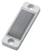


E39-R52
Reflector, E3S-DB Transparent Object Sensor, 0 to 700mm
- Manufacturer: OMRON INDUSTRIAL AUTOMATION
- Product type:
- SVHC: To Be Advised
| Delivery and price | |
|---|---|
| Units per pack | 1 |
| Price | 22.79 € |
| Current stock | 10+ |
| Lead time | 30 days |
**Transparent object sensor E3S-DB** ## **Outstanding detection performance for all kinds of transparent objects** - Most reliable detection of all transparent objects such as PET bottles, glass bottles or transparent trays - SmartTeach for fast set up and optimum threshold setting - Sensing distance up to 4.5 m - Narrow beam types with 2 mm spot detecting smallest gaps - Proven for environments in Food & Beverage industry ## **Ordering Information** ## **Sensors** |**Sensor type**|**Sensitivity**<br>**adjustment**|**Connection method**|**Sensing distance, typ.**|**Model**|**Model**| |---|---|---|---|---|---| |||||**NPN output**|**PNP output**| |Retro-reflective<br>with MSR function|SmartTeach|Pre-wired (2 m)|0 to 4.5 m with E39-R8|**E3S-DBN11 2M**|**E3S-DBP11 2M**| |||Connector<br>(M12, 4 pins)||**E3S-DBN21**|**E3S-DBP21**| |||Pigtail Connector*1<br>(M12, 4 pins)||**E3S-DBN31**|**E3S-DBP31**| |||Pre-wired (2 m)|Narrow beam<br>0 to 0.7 m with E39-R21|**E3S-DBN12 2M**|**E3S-DBP12 2M**| |||Connector<br>(M12, 4 pins)||**E3S-DBN22**|**E3S-DBP22**| |||Pigtail Connector*1<br>(M12, 4 pins)||**E3S-DBN32**|**E3S-DBP32**| ||Trimmer<br>(11 turns)|Pre-wired (2 m)|0 to 4.5 m with E39-R8|**E3S-DBN11T 2M**|**E3S-DBP11T 2M**| |||Connector<br>(M12, 4 pins)||**E3S-DBN21T**|**E3S-DBP21T**| |||Pigtail Connector*1<br>(M12, 4 pins)||**E3S-DBN31T**|**E3S-DBP31T**| |||Pre-wired (2 m)|Narrow beam<br>0 to 0.7 m with E39-R21|**E3S-DBN12T 2M**|**E3S-DBP12T 2M**| |||Connector<br>(M12, 4 pins)||**E3S-DBN22T**|**E3S-DBP22T**| |||Pigtail Connector*1<br>(M12, 4 pins)||**E3S-DBN32T**|**E3S-DBP32T**| > *1 OMRON SmartClick connector for fast and save connection. **1** ## **E3S-DB** ## **Reflectors [Refer to** _**Dimensions on page 9.**_ **]** **Reflectors required for Retro-reflective Sensors: A Reflector is not provided with the Sensor. Be sure to order a Reflector separately.** |**Sensor**|**Sensing distance,**<br>**typ.**|**Appearance**|**Dimensions**<br>**[mm]**|**Remarks**|**Model**| |---|---|---|---|---|---| |E3S-DB__1(T)|0 to 4.5 m||100 × 100||**E39-R8**| ||0 to 3.5 m||60 × 40||**E39-R1S**| ||0 to 3 m||60 × 40|Special polarizing filter for<br>enhanced PET detection|**E39-RP1**| |E3S-DB__2(T)|0 to 700 mm||35 × 30|For narrow gap detection|**E39-R21**| ||0 to 700mm||60 × 20||**E39-R52**| Note: For more reflectors please check OMRON catalogue or contact your OMRON representative. ## **Mounting brackets [Refer to** _**Dimensions on page 9.**_ **]** **A Mounting Bracket is not enclosed with the Sensor. Order a Mounting Bracket separately if required.** |**Appearance**|**Material**|**Remarks**||||**Model**| |---|---|---|---|---|---|---| ||SUS304|A Mounting bracket is not provided with the Sensor.|A Mounting bracket is not provided with the Sensor.|||**E39-L192**| |eo|SUS304|A Mounting bracket is not provided with the Sensor.|A Mounting bracket is not provided with the Sensor.|||**E39-L193**| |**Sensor I/O connectors**||||||| |**Size**|**Specifications**<br>**Appearance**<br>**Cable type**<br>~~es~~|||||**Model**| |M12 (4 pins)|Standard PVC<br>Straight<br>2 m<br>5 m<br>Angled<br>2 m<br>5 m<br>Smartclick PVC<br>Straight<br>2 m<br>5 m<br>~~i~~<br>~~==~~<br>~~|~~||||4-wire|**XS2F-M12PVC4S2M-EU**<br>**XS2F-M12PVC4S5M-EU**<br>**XS2F-M12PVC4A2M-EU**<br>**XS2F-M12PVC4A5M-EU**<br>**XS5F-D421-D80-F**<br>**XS5F-D421-G80-F**| ## **Sensor I/O connectors** **2** **E3S-DB** ## **Ratings and Specifications** |**Sensing method**|**Sensing method**|**Retro-reflective with MSR function**|**Retro-reflective with MSR function**|**Retro-reflective with MSR function**|**Retro-reflective with MSR function**| |---|---|---|---|---|---| |**Model**|**NPN output**|**E3S-DBN_1**|**E3S-DBN_1T**|**E3S-DBN_2**|**E3S-DBN_2T**| |**Item**|**PNP output**|**E3S-DBP_1**|**E3S-DBP_1T**|**E3S-DBP_2**|**E3S-DBP_2T**| |**Sensing distance, typ.*1**||0 to 4.5 m (with E39-R8)||0 to 700 mm (with E39-R21)|| |**Sensing distance, recommended*2**||0 to 3.5 m (with E39-R8)||0 to 500 mm (with E39-R21)|| |**Light source (wavelength)**||Red LED (624 nm)|||| |**Power supply voltage**||10 to 30 VDC, including 10% ripple (p-p)|||| |**Current consumption**||720 mW max. (24 VDC, 30 mA)|||| |**Control output**||Load power supply voltage: 30 VDC max., Load current: 100 mA max.<br>(Residual voltage: 2 V max.)<br>NPN/PNP transistor output (depending on model)|||| |**Operating modes**||OUT1: L-ON/OUT2: D-ON (antivalent output)|||| |**Protection circuits**||Reversed power supply polarity protection, Output short-circuit protection,<br>Reversed output polarity protection, Missconnection protection,<br>Mutual interference suppression|||| |**Response time**||0.5 ms|||| |**Sensitivity adjustment**||SmartTeach|11-turn trimmer|SmartTeach|11-turn trimmer| |**Auto-Compensation function**<br>**(AC3)**||yes (default = OFF)|–|yes (default = OFF)|–| |**Lock function**||yes|–|yes|–| |**Ambient illumination**||Incandescent lamp: 3,000 lx max./Sunlight: 10,000 lx max.|||| |**Ambient temperature range**||Operating: –25 to 60°C/Storage: –40 to 70°C (with no icing or condensation)|||| |**Ambient humidity range**||Operating: 35 to 85% RH/Storage: 35 to 95% RH (with no condensation)|||| |**Insulation resistance**||20 Mmin. at 500 VDC|||| |**Dielectric strength**||1,000 VAC at 50/60Hz for 1min. Between current-carrying parts and case|||| |**Vibration resistance**||Destruction: 10 to 55 Hz, 1.5 mm double amplitude for 2 hours each in X,Y,Z directions|||| |**Shock resistance**||Destruction: 500 m/s², 3 times each in X,Y,Z directions|||| |**Degree of protection**||IEC: IP67, DIN 40050-9: IP69K|||| |**Connection method**||Pre-wired cable (standard length: 2 m) or M12 4-pin connector or Pigtail (0.3 m/M12 4-pin)|||| |**Indicators**||Light indicator (orange), Stability indicator (green)|||| |**Weight (packed state)**||Approx. 40 g|||| |**Materials**|**Housing**|PBT/ABS|||| ||**Lens & indicators**|PMMA (Polymethylmethacrylate)|||| ||**Buttons**|Elastomer|||| ||**Cable**|PVC|||| |**Accessories**||Instruction manual|||| > *1 Maximum sensing distance for typical reflector and sensor > *2 Operating sensing distance recommended for factory environments **3** **E3S-DB** ## **Engineering Data (Reference Value)** ## **Parallel Operating Range** ## **E3S-DB@@1(T)** ## **E3S-DB@@2(T)** **==> picture [511 x 362] intentionally omitted <==** **----- Start of picture text -----**<br> 100 20<br>Reflector : E39-R8 Reflector : E39-R21<br>80 Y Y<br>15<br>60 X X<br>10<br>40<br>5<br>20<br>0 0<br>-20<br>-5<br>-40<br>-10<br>-60<br>-15<br>-80<br>-100 -20<br>0.0 1.0 2.0 3.0 4.0 5.0 6.0 0.0 0.2 0.4 0.6 0.8 1.0 1.2 1.4 1.6<br>Distance X (m) Distance X (m)<br>Excess Gain vs. Distance<br>E3S-DB@@1(T) E3S-DB@@2(T)<br>100.0 100.0<br>E39-R50<br>E39-R8<br>10.0 10.0<br>E39-R1S<br>E39-R21<br>E39-RP1<br>1.0 1.0<br>E39-RS2<br>0.1 0.1<br>0.00 0.50 1.00 1.50 2.00 2.50 3.00 3.50 4.00 4.50 5.00 0.00 0.50 1.00 1.50 2.00 2.50 3.00<br>Distance (m) Distance (m)<br>Distance Y (mm) Distance Y (mm)<br>Excess gain ratio (multiple) Excess gain ratio (multiple)<br>**----- End of picture text -----**<br> ## **Spot size vs. Distance E3S-DB@@1(T)** ## **E3S-DB@@2(T)** **==> picture [502 x 164] intentionally omitted <==** **----- Start of picture text -----**<br> 250 25<br>200 20<br>150 15<br>100 10<br>50 5<br>0 0<br>0 0.5 1 1.5 2 2.5 3 3.5 4 4.5 5 0 100 200 300 400 500 600 700 800 900 1000<br>Distance (m) Distance (mm)<br>) (mm) ) (mm)<br>Φ Φ<br>Spot size ( Spot size (<br>**----- End of picture text -----**<br> **4** **E3S-DB** ## **Attenuation level vs. Sensing Object Characteristics (typical values) E3S-DB@@1(T)** With standard reflector, e.g. E39-R1S or E39-R8 **==> picture [505 x 473] intentionally omitted <==** **----- Start of picture text -----**<br> With standard reflector, e.g. E39-R1S or E39-R8 With p-opaquing reflector E39-RP1<br>100% 100%<br>90% 90%<br>1.75 m 1.25 m<br>80% 3.5 m 80% 2.5 m<br>70% 70%<br>60% 60%<br>50% 50%<br>40% 40%<br>30% 30%<br>20% 20%<br>10% 10%<br>0% 0%<br>PET bottle PET bottle GLASS bottle GLASS bottle Transparent Transparent PET bottle - Empty PET bottle - Transparent film<br>- Empty - Filled with - Empty - Filled with film (from tray Filled with water (from Tabacco case)<br>water water Tabacco case)<br>E3S-DB@@2(T)@@2(T)2(T)<br>With reflector E39-R21<br>100%<br>90%<br>250 mm<br>80% 500 mm<br>70%<br>60%<br>50%<br>40%<br>30%<br>20%<br>10%<br>0%<br>PET bottle PET bottle GLASS bottle GLASS bottle Transparent Transparent<br>- Empty - Filled with - Empty - Filled with film (from tray<br>water water Tabacco case)<br>Attenuation level Attenuation level<br>Attenuation level<br>**----- End of picture text -----**<br> ## **E3S-DB@@2(T)@@2(T)2(T)** With reflector E39-R21 **5** **E3S-DB** **Output circuit diagram** ## **NPN Output** **==> picture [511 x 117] intentionally omitted <==** **----- Start of picture text -----**<br> Timing charts<br>Model Output circuit<br>Output 1 (pin 4) Output 2 (pin 2)<br>+ 10 to 30 VDC<br>Light Stability 1<br>Incident light Incident light indicator(Orange) (Green)indicator Load1<br>Operation indicator No incident lightON Operation indicator No incident lightON Photo- 4 OUT1Light ON Load2<br>E3S-DBN__ (orange)Output transistor OFFOFFON (orange)Output transistor OFFOFFON electric Sensor Main Circuit 2 OUT2Dark ON<br>Load Operate Load Operate<br>(e.g., relay) Reset (e.g., relay) Reset<br>3<br>– 0 V<br>**----- End of picture text -----**<br> ## **PNP Output** **==> picture [511 x 117] intentionally omitted <==** **----- Start of picture text -----**<br> Timing charts<br>Model Output circuit<br>Output 1 (pin 4) Output 2 (pin 2)<br>+ 10 to 30 VDC<br>Light Stability 1<br>indicator indicator<br>Incident light Incident light (Orange) (Green)<br>Operation indicator No incident lightON Operation indicator No incident lightON Photo- 4 OUT1Light ON<br>E3S-DBP__ (orange)Output transistor OFFOFFON (orange)Output transistor OFFOFFON electric Sensor Main Circuit 2 OUT2Dark ON Load1<br>Load Operate Load Operate<br>(e.g., relay) Reset (e.g., relay) Reset Load2<br>3<br>– 0 V<br>**----- End of picture text -----**<br> **Connector Pin Arrangement M12 Connector Pin Arrangement** **==> picture [30 x 30] intentionally omitted <==** **----- Start of picture text -----**<br> 1<br>2 4<br>3<br>**----- End of picture text -----**<br> **Connectors (Sensor I/O connectors) M12 4-wire Connectors** |2<br>4<br>1|3<br>1<br>2<br>3<br>4<br>Pin|Brown<br>Blue<br>White<br>Black<br>No.<br>Wire color|Brown<br>Blue<br>White<br>Black<br>No.<br>Wire color|Brown<br>Blue<br>White<br>Black<br>No.<br>Wire color| |---|---|---|---|---| |**Classification**|**Wire color**<br>**C**||**onnector pin No.**|**Application**| |DC|Brown||➀|Power supply (+V)| ||White||➁|Output2 (Dark ON)| ||Blue||➂|Power supply (0 V)| ||Black||➃|Output1 (Light ON)| **6** **E3S-DB** ## **Operation** ## **Activation/ Deactivation of Lock function (SmartTeach only)** ## **Adjusting Trimmer type (11-turn)** 1. Install the sensor and reflector and adjust the optical axis (without object). Light indicator (Orange) should be ON. 1. Press Teach button between 5 to 10 sec. until orange LED flashes with medium speed.* @ Orange LED: Flash (medium speed) - Orange LED: ON Green LED: ON * If Lock function is already active, orange LED stays OFF for the first 5 sec pushing. If Lock function is OFF, If Lock function is ON, Then Green LED is OFF. Then Green LED is ON. Lock function is O Lock function is OFF O already ON Green LED: OFF Green LED: ON 2. Turn the sensitivity adjuster to minus until orange indicator LED turns OFF. ## O@ Orange LED: OFF Green LED: ON 3. Turn the sensitivity adjuster to plus and stop at the position where the orange output LED changes state from OFF to ON and green stability LED is on. 2. Release Teach button during Orange LED is flashing. **==> picture [128 x 9] intentionally omitted <==** **----- Start of picture text -----**<br> Orange LED: ON Green LED: ON<br>**----- End of picture text -----**<br> ’ Orange LED and Green LED flash one time. Lock function Activation/Deactivation is completed. 4. Confirm correct operation by testing stable detection with object Note: For opaque object set the sensitivity adjuster to maximum. ## **Adjusting SmartTeach type** Orange LED: Green LED: Flash one time Flash one time oO Lock function activated Lock function deactivated 1. Install the Sensor and Reflector and adjust the optical axis. (without object) ## **Activation/Deactivation of AC3 Auto compensation function (SmartTeach only)** 2. Set the trimmer threshold to the desired level. Typical values are: • Opaque and semi-transparent objects: 30% • Transparent trays, glass and PET bottles: 20 to 25% • Transparent film: 10 to 15% 3. Press Teach button between 1 to 5 sec, until orange LED flashes with low speed Orange LED: Green LED: OFF Flash (low speed) 1. Press Teach button > 10 sec. until orange LED flashes with high speed. Orange LED: Flash (high speed) Oe If AC3 is OFF, If AC3 is already ON, Then Green LED is OFF. Then Green LED is ON. O AC3 is OFF @ AC3 is already ON Green LED: OFF Green LED: ON 2. Release Teach button during Orange LED is flashing. Orange LED and Green LED flash one time. Teaching is completed. Orange LED: Green LED: Flash one time Flash one time 4. Confirm correct operation by testing stable detection with object Orange LED and Green LED flash one time. Then AC3 Activation/Deactivation is completed. Orange LED: Green LED: Flash one time Flash one time oO Lock function activated Lock function deactivated Note: • Default value of AC3 is OFF. - If Lock function is activated, please deactivate Lock function first **7** **E3S-DB** ## **Safety Precautions** ## **Refer to** _**Warranty and Limitations of Liability**_ **.** ## **WARNING** **This product is not designed or rated for directly or indirectly ensuring safety of persons. Do not use it for such a purpose.** ## **CAUTION** **Never use the product with an AC power supply. Do not use the product with voltage in excess of the rated voltage.** **Do not use the product with incorrect wiring. Otherwise, explosion, fire, malfunction may result.** the rated values because it might deteriorate the degree of protection. 11. Perform sensitivity adjustment with the torque of 0.06 N·m or less. 12. Do not exert excessive force on the connector section. 13. This product cannot be used as a detection system to protect human body. 14. These sensors are certificated by the UL standard on the assumption of usage in class 2 circuit. Please use it with “Class 2 power supply” in the United States or Canada.The accessory cable assembly, Recognized XS2F-D4 Series and/or Recognized XS2W-D4 Series by Omron shall be used. Cables that have wires less than 24 AWG (0.2 mm²) are for connection to terminal blocks and are not for field splicing. External overcurrent protection of 1 A for 26 AWG, 2 A for 24 AWG, or 3 A for 22 AWG wire shall be provided for cable protection. 15. Output pulses may be generated when the power supply is turned off or turned on within short period after turning off the power supply, so be sure to turn off power supplies of other devices or loads first. ## **Precautions for Safe Use** Be sure to follow the safety precautions below for added safety. 1. Do not use the sensor under the environment with explosive, flammable or corrosive gas. 2. Do not use the sensor under the oil or chemical environment. 3. Do not use the sensor in the water, rain or outdoors. 4. Do not use the sensor under the environment under the other conditions in excess of rated. 5. Do not use the sensor in place that is exposed by direct sunlight. 6. Do not use the sensor in place where the sensor may receive direct vibration or shock. 7. Do not use the thinner, alcohol, or other organic solvents. 8. Never disassemble, repair nor tamper with the sensor. 9. Please process it as industrial waste. 10. Do not use the high concentration cleaning agent because it might cause the trouble. Avoid the jet of high-pressure water over ## **Precautions for Correct Use** Be sure to follow the safety precautions below for added safety 1. Laying Sensor wiring in the same conduit or duct as high-voltage wires or power lines may result in malfunction or damage due to conduit or use shielded cable. 2. If a commercial switching regulator is used, ground the FG (frame ground) terminal. 3. The sensor will be available 100 ms after the power supply is tuned ON. Start to use the sensor 100 ms or more after turning ON the power supply. If the load and the sensor are connected to separate power supplies, be sure to turn ON the sensor first. 4. Output pulses may be generated even when the power supply is OFF. Therefore, it is recommended to first turn OFF the power supply for the load or the load line. **8** **E3S-DB** (Unit: mm) ## **Dimensions** Tolerance class IT16 applies to dimensions in this data sheet unless otherwise specified. ## **Sensors** ## **E3S-DB___** **==> picture [511 x 491] intentionally omitted <==** **----- Start of picture text -----**<br> LIGHT INDICATOR (ORANGE) STABILITY INDICATOR (GREEN) NOTE<br>1.REFER BELOW FOR PIN'S CONFIGURATION.<br>SENSITIVITY ADJ.<br>TUNING BUTTON<br>PIN No. APPLICATION<br>1 +V<br>2 1 2 OUT2(D-ON)<br>3 0V<br>4 OUT1(L-ON)<br> 55.5<br> 40.5 A 3 4<br> 36<br> 29.9<br> 15.8 3.2 19.4<br> 12.9<br>OPTICAL AXIS<br>MATERIAL PMMA<br> 29.9 ±0.1<br> (33) CONNECTOR MOUNTING SCREW HOLES<br>M12<br>E3S-DB___(T)<br>LIGHT INDICATOR (ORANGE) STABILITY INDICATOR (GREEN)<br>SENSITIVITY ADJ. NOTE<br>1.REFER BELOW FOR PIN'S CONFIGURATION.<br>PIN No. APPLICATION<br>2 1<br> 55.5 1 +V<br> 40.5 2 OUT2(D-ON)<br> 36 3 0V<br> 29.9 4 OUT1(L-ON)<br> 15.8 3.2 19.4 12.9 A 3 4<br>OPTICAL AXIS<br>MATERIAL PMMA<br> 29.9 ±0.1<br> (33) CONNECTOR<br>M12 MOUNTING SCREW HOLES<br>9.4 DIA ( LENS S IZE )<br> 2-M 4<br>9.4 DIA (LENS SIZE)<br> 2-M 4<br>4.2<br> 3-<br>4.2<br> 3-<br> 2- R2.1<br> 2- R2.1<br>(53°)<br>(53°)<br> 2- R2.1<br> 2- R2.1<br> 15.6<br> 4.2<br> 17<br> 20<br> 41<br> 40 5.4 48.5<br> (63.5) 40 ±0.1<br> 15.6<br> 4.2<br> 17<br> 20<br> 41<br> 40 5.4 48.5<br> (63.5) 40 ±0.1<br>**----- End of picture text -----**<br> **9** **E3S-DB** ## **Accessories (Order Separately) Reflector** ## **E39-R8** **==> picture [497 x 452] intentionally omitted <==** **----- Start of picture text -----**<br> E39-R21<br>9 100 - 30 . 2-Ø3.2<br>2.5 25 5<br>3<br>92 7<br>5 F5 N |i= :a<br>oR=a,<br>Ree 35 25 29<br>oeoe<br>ac<br>oSa e a<br>— \<br>_ 92 100 3 24<br>_<br>_ . \ E39-R52<br>_<br>_ | 5[ |<br>| for M3 _ .a8 e elee : eee©<br>, : a Lo<br>37.8 3.2<br>50 6±0.3<br>60<br>Mounting bracket<br>E39-L193<br> 42,9 7 7<br> 29,9 (3) 6,5 6,5<br>tda R—_4 oy | ¢—1| D | =p——|| S|<br> 4,5 |<br>.|’ e el I ,oiv, o<br>(+f SS => [m] [s] = ) | rt}<br>| |<br>| | 31,8 Cp Py | CA<br>10,1<br> 54,5 10<br>7 10<br> 15 25<br>—_—|<br>|<br> 3<br> 20° 20°<br> R2,25<br> R49,9 ±0,1<br> R3,5 4,5 4,5<br> R5 max. R3<br> 90°<br>±0,5°<br>±0,1<br> R20<br> 5°<br> R20<br>±0,1<br> (6x)R2,25<br> R1<br> (2x)<br>4,5<br> R1<br> 90° ±0,5°<br> (6x)R2,25<br> (2x)R5<br>4,5<br> R25<br>±0,1<br> R2,25<br> R2,25<br>20 16.7 Ø4.6 Ø7.5<br>,9 3,9<br> 3<br> 5<br> 40 ±01, 4,5 20 25,4 61,8 58,8 20 ±01, 11,4 35 11,4 20 0,1±<br> 23,8<br> 8,8<br> (3)<br> R2,25 3<br> 18,3<br> 28,8<br> 25<br> 30°<br>**----- End of picture text -----**<br> **Mounting bracket E39-L192** ALL DIMENSIONS SHOWN ARE IN MILLIMETERS. To convert millimeters into inches, multiply by 0.03937. To convert grams into ounces, multiply by 0.03527. Cat. No. E99E-EN-02A In the interest of product improvement, specifications are subject to change without notice. **10** **E3S-DB** **11** ## **Terms and Conditions Agreement** ## **Read and understand this catalog.** Please read and understand this catalog before purchasing the products. Please consult your OMRON representative if you have any questions or comments. ## **Warranties.** (a) Exclusive Warranty. Omron’s exclusive warranty is that the Products will be free from defects in materials and workmanship for a period of twelve months from the date of sale by Omron (or such other period expressed in writing by Omron). Omron disclaims all other warranties, express or implied. (b) Limitations. OMRON MAKES NO WARRANTY OR REPRESENTATION, EXPRESS OR IMPLIED, ABOUT NON-INFRINGEMENT, MERCHANTABILITY OR FITNESS FOR A PARTICULAR PURPOSE OF THE PRODUCTS. BUYER ACKNOWLEDGES THAT IT ALONE HAS DETERMINED THAT THE PRODUCTS WILL SUITABLY MEET THE REQUIREMENTS OF THEIR INTENDED USE. Omron further disclaims all warranties and responsibility of any type for claims or expenses based on infringement by the Products or otherwise of any intellectual property right. (c) Buyer Remedy. Omron’s sole obligation hereunder shall be, at Omron’s election, to (i) replace (in the form originally shipped with Buyer responsible for labor charges for removal or replacement thereof) the non-complying Product, (ii) repair the non-complying Product, or (iii) repay or credit Buyer an amount equal to the purchase price of the non-complying Product; provided that in no event shall Omron be responsible for warranty, repair, indemnity or any other claims or expenses regarding the Products unless Omron’s analysis confirms that the Products were properly handled, stored, installed and maintained and not subject to contamination, abuse, misuse or inappropriate modification. Return of any Products by Buyer must be approved in writing by Omron before shipment. Omron Companies shall not be liable for the suitability or unsuitability or the results from the use of Products in combination with any electrical or electronic components, circuits, system assemblies or any other materials or substances or environments. Any advice, recommendations or information given orally or in writing, are not to be construed as an amendment or addition to the above warranty. See http://www.omron.com/global/ or contact your Omron representative for published information. ## **Limitation on Liability; Etc.** OMRON COMPANIES SHALL NOT BE LIABLE FOR SPECIAL, INDIRECT, INCIDENTAL, OR CONSEQUENTIAL DAMAGES, LOSS OF PROFITS OR PRODUCTION OR COMMERCIAL LOSS IN ANY WAY CONNECTED WITH THE PRODUCTS, WHETHER SUCH CLAIM IS BASED IN CONTRACT, WARRANTY, NEGLIGENCE OR STRICT LIABILITY. Further, in no event shall liability of Omron Companies exceed the individual price of the Product on which liability is asserted. ## **Suitability of Use.** Omron Companies shall not be responsible for conformity with any standards, codes or regulations which apply to the combination of the Product in the Buyer’s application or use of the Product. At Buyer’s request, Omron will provide applicable third party certification documents identifying ratings and limitations of use which apply to the Product. This information by itself is not sufficient for a complete determination of the suitability of the Product in combination with the end product, machine, system, or other application or use. Buyer shall be solely responsible for determining appropriateness of the particular Product with respect to Buyer’s application, product or system. Buyer shall take application responsibility in all cases. NEVER USE THE PRODUCT FOR AN APPLICATION INVOLVING SERIOUS RISK TO LIFE OR PROPERTY OR IN LARGE QUANTITIES WITHOUT ENSURING THAT THE SYSTEM AS A WHOLE HAS BEEN DESIGNED TO ADDRESS THE RISKS, AND THAT THE OMRON PRODUCT(S) IS PROPERLY RATED AND INSTALLED FOR THE INTENDED USE WITHIN THE OVERALL EQUIPMENT OR SYSTEM. ## **Programmable Products.** Omron Companies shall not be responsible for the user’s programming of a programmable Product, or any consequence thereof. ## **Performance Data.** Data presented in Omron Company websites, catalogs and other materials is provided as a guide for the user in determining suitability and does not constitute a warranty. It may represent the result of Omron’s test conditions, and the user must correlate it to actual application requirements. Actual performance is subject to the Omron’s Warranty and Limitations of Liability. ## **Change in Specifications.** Product specifications and accessories may be changed at any time based on improvements and other reasons. It is our practice to change part numbers when published ratings or features are changed, or when significant construction changes are made. However, some specifications of the Product may be changed without any notice. When in doubt, special part numbers may be assigned to fix or establish key specifications for your application. Please consult with your Omron’s representative at any time to confirm actual specifications of purchased Product. ## **Errors and Omissions.** Information presented by Omron Companies has been checked and is believed to be accurate; however, no responsibility is assumed for clerical, typographical or proofreading errors or omissions.
Updated at June 9, 2026
With a legacy spanning over 80 years, Omron Industrial Automation is a globally recognized leader in the manufacture of advanced industrial control and automation components. Renowned for their reliability and engineering excellence, Omron delivers comprehensive solutions that enhance efficiency, machine safety, and precision across a wide range of manufacturing environments. Our extensive portfolio of Omron products is heavily focused on their industry-leading sensing and switching technologies. We offer a vast selection of sensors, excelling specifically in high-performance proximity sensors, light sensors, and temperature sensors. Complementing this range are robust switching solutions, featuring a deep inventory of power relays, solid-state relays, safety relays, and essential relay accessories designed for demanding operational requirements. Beyond sensing and switching, Omron is highly regarded for its precision automation and process control equipment. Our selection features highly accurate temperature controllers, versatile process controllers, and sophisticated panel displays and instrumentation. To support these fundamental systems, we also supply dependable Omron power supplies, notably AC/DC converters, alongside vital connectivity components like DIN rail terminal blocks to ensure secure, efficient, and complete industrial setups.
About Novapart
Novapart is a B2B electronic component broker specialising in stock shortages and cost reduction. We source hard-to-find parts and identify compliant alternatives across a catalogue of 410,000+ components from 500+ manufacturers.
Learn more →Stock Shortage Specialist
When a component is unavailable, discontinued or has an unacceptable lead time, we tap into our network of vetted European and Asian distributors to source what you need — without compromising on quality or traceability.
Request a quote →Compliant Alternatives
We identify pin-to-pin, electrically equivalent substitutes that meet the same certifications (RoHS, AEC-Q100, REACH) as your original specification — validated against datasheets, not just part numbers. Often at a lower cost.
BOM Analysis service →