


E39-R49
Reflector, E3FZ Retro-Reflective Sensors, Snap-Fit Mounting
- Manufacturer: OMRON INDUSTRIAL AUTOMATION
- Product type:
- SVHC: To Be Advised
| Delivery and price | |
|---|---|
| Units per pack | 1 |
| Price | 8.48 € |
| Current stock | 10+ |
| Lead time | 30 days |
Easy mounting photoelectric sensor in short M18 housing
## **E3FZ/E3FR**
- Secure-click snap mounting for fast installation
- High power LED for enhanced sensing distance
- Short housing with less than 40 mm length
- Minimal optical axis deviation for easy alignment
## **Features** ~~OT~~
## **Easy and fast installation**
The **SecureClick** snap mounting mechanism provides easy installation in 2 steps and enhanced protection against vibration.
Installation time can be reduced by up to 10 times compared to conventional sensors.
**==> picture [109 x 134] intentionally omitted <==**
**----- Start of picture text -----**<br>
Conventional Conventional E3FZ with<br>square sensors cylindrical SecureClick*<br>sensors<br>Up to 3 times faster<br>Up to 10 times faster<br>**----- End of picture text -----**<br>
**==> picture [76 x 42] intentionally omitted <==**
**----- Start of picture text -----**<br>
>>CLICK<br>2<br>1<br>**----- End of picture text -----**<br>
*SecureClick has been tested to withstand severe vibrations.
**E3FZ/E3FR**
1
## Ordering Information
Snap mounting – E3FZ[*2]
|Sensor type|Sensing distance|Connection method|Connection method|Connection method|Connection method|Order code|Order code|
|---|---|---|---|---|---|---|---|
|||||||NPN output|PNP output|
|Through-beam|15 m|–|–|2 m|–*3|E3FZ-T61H 2M|E3FZ-T81H 2M|
|||–|�|–|–*3|E3FZ-T66H|E3FZ-T86H|
|Retroreflective with M.S.R.|0.1 to 4 m*1|–|–|2 m|–*3|E3FZ-R61H 2M|E3FZ-R81H 2M|
|||–|�|–|–*3|E3FZ-R66H|E3FZ-R86H|
|Diffuse reflective|1 m (adjustable)|–|–|2 m|–*3|E3FZ-D62 2M|E3FZ-D82 2M|
|||–|�|–|–*3|E3FZ-D67|E3FZ-D87|
|Diffuse reflective<br>(background suppression)|100 mm (fixed)|–|–|2 m|–*3|E3FZ-LS61H 2M|E3FZ-LS81H 2M|
|||–|�|–|–*3|E3FZ-LS66H|E3FZ-LS86H|
||200 mm (fixed)|–|–|2 m|–*3|E3FZ-LS64H 2M|E3FZ-LS84H 2M|
|||–|�|–|–*3|E3FZ-LS69H|E3FZ-LS89H|
|Radial mounting – E3FR||||||||
|Sensor type|Sensing distance|Connection method||||Order code||
|||||||NPN output|PNP output|
|Through-beam|15 m|–|–|2 m|–*3|E3FR-T61H 2M|E3FR-T81H 2M|
|||–|�|–|–*3|E3FR-T66H|E3FR-T86H|
|Retroreflective with M.S.R.|0.1 to 4 m*1|–|–|2 m|–*3|E3FR-R61H 2M|E3FR-R81H 2M|
|||–|�|–|–*3|E3FR-R66H|E3FR-R86H|
|Diffuse reflective|1 m (adjustable)|–|–|2 m|–*3|E3FR-D62 2M|E3FR-D82 2M|
|||–|�|–|–*3|E3FR-D67|E3FR-D87|
|Diffuse reflective<br>(background suppression)|100 mm (fixed)|–|–|2 m|–*3|E3FR-LS61H 2M|E3FR-LS81H 2M|
|||–|�|–|–*3|E3FR-LS66H|E3FR-LS86H|
||200 mm (fixed)|–|–|2 m|–*3|E3FR-LS64H 2M|E3FR-LS84H 2M|
|||–|�|–|–*3|E3FR-LS69H|E3FR-LS89H|
- *1. Measured with reflector E39-R1S
The reflector is sold separately.
- *2. Mounting with Snap-Holder (provided with product) or M18 Nuts (provided with product) possible.
- *3. Pre-wired connectors are available on request (item description see "Model Number Legend" on page 4)
Standard Photoelectric Sensors
2
## Accessories
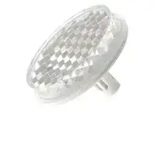
## Reflectors
|Shape|Type|Material|Features|Size in mm|Applicable Sensor|Order code|
|---|---|---|---|---|---|---|
||General purpose<br>reflectors|- ABS base<br>- Acrylic surface|Surface screw<br>mounting<br>(diagonal holes)|59.9x40.3x7.5|- Retroreflective<br>photo electric<br>sensors –<br>non polarizing<br>- Retroreflective<br>photo electric<br>sensors –<br>polarizing (MSR)|E39-R1S|
||||Snap mounting|dia 30 mm<br>(reflector)<br>dia 6.5 mm<br>(snap mount)||E39-R49|
## Mounting brackets
|Shape|Type||Material||Features||Applicable Sensor|Order code|
|---|---|---|---|---|---|---|---|---|
||General purpose||stainless steel||Horizontal angle adjustment||E3FZ (dia 20mm|E39-EL8|
||mounting||||||snap holder)||
|ul|||||||||
|ra|||||||||
||Telescope||||3D rotation (fits to 12 mm mounting|||E39-EL9|
||mounting||||rod)||||
|Sensor I/O connectors|||||||||
|Straight||2 m||4-wire||PVC|XS2F-D421-D80-A||
|||||||PUR|Y92E-M12PUR4S2M-L||
|||5 m||||PVC|XS2F-D421-G80-A||
|||||||PUR|Y92E-M12PUR4S5M-L||
|L-shaped||2 m<br>PVC<br>XS2F-D422-D80-A<br>PUR<br>Y92E-M12PUR4A2M-L<br>~~——~~|||||||
|||5 m||||PVC|XS2F-D422-G80-A||
|||||||PUR|Y92E-M12PUR4A5M-L||
## Sensor I/O connectors
Note: For the complete list of sensor I/O connectors refer to E26E Accessories datasheet.
**E3FZ/E3FR**
3
Model Number Legend
E3F@-@@@@-@-@@
1 2 3 4 5 6 7 8 9
e.g., E3FZ-T81H; short housing/ through-beam/PNP output/2 m cable/without an adjustor/L-on/D-on by wire/
E3FZ-T86H-D; short housing/through-beam/PNP output/M12 connector/without an adjustor/L-on/D-on by wire/receiver E3FR-LS86; radial housing/background-suppression/PNP output/M12 connector/sensing distance of 100 mm/without an adjustor/ L-on/D-on by wire/
1. Cylindrical family name: E3F
2. Series name
- 2: standard housing (seperate naming rule)
- Z: short housing R: radial housing
3. Sensing method
- T: through-beam
- R: retroreflective
- D: diffuse reflective
- LS: background suppression
4. Output
- 6: NPN output 8: PNP output
5. Connection
Through-beam, retroreflective types
- 1: 2 m cable
- 6: M12 connector
Diffuse reflective types
- 2: 2 m cable
6. Adjuster
Blank: with volume adjuster/L-on/D-on by wire H: without volume adjuster/L-on/D-on by wire
7. Emitter/ Receiver
- L: emitter
- D: receiver
8. Kind of connection
Blank: standard 2 m cable or M12 connector
- M1J: pre-wired with 30 cm cable and M12 plug connector (4 pin)
M3J: pre-wired with 30 cm cable and M8 plug connector (4 pin)
M5J: pre-wired with 30 cm cable and M8 plug connector (3 pin)
M1TJ: pre-wired with 30cm cable and Twist&Click M12 plug connector (4 pin)
9. Cable length
Blank: M12 connector
Number: cable length
- 7: M12 connector
Background suppression types
- 1: 2 m cable/sensing distance of 100 mm
- 4: 2 m cable/sensing distance of 200 mm
- 6: M12 connector/sensing distance of 100 mm
- 9: M12 connector/sensing distance of 200 mm
Standard Photoelectric Sensors
4
Mounting and dismounting
**==> picture [488 x 291] intentionally omitted <==**
**----- Start of picture text -----**<br>
Mounting<br>Step 1 2.5 to 2.9 mm<br>_ A<br>a) |<br>a) Me.<br>Insert the snap holder into the Verify the correct position<br>mounting hole from the front (a clicking sound can be heard)<br>Step 2<br>Insert the sensor into the snap Verify the correct position<br>holder from the back (a clicking sound can be heard)<br>dia 20.1 to 20.2 mm<br>**----- End of picture text -----**<br>
## Dismounting
**==> picture [362 x 132] intentionally omitted <==**
**----- Start of picture text -----**<br>
Step 1<br>Apply soft pressure to the sensor Remove the sensor<br>lens in the indicated areas (e.g. with<br>two thumbs)<br>**----- End of picture text -----**<br>
## Step 2
**==> picture [354 x 21] intentionally omitted <==**
**----- Start of picture text -----**<br>
Press down both snap-fits and push Remove the snap holder<br>the snap holder forward.<br>**----- End of picture text -----**<br>
**E3FZ/E3FR**
5
Specifications
|Item<br>~~ee~~|Item<br>~~ee~~|Through-beam|Retroreflective|Diffuse reflective|
|---|---|---|---|---|
|||E3FZ-T / E3FR-T|E3FZ-R / E3FR-R|E3FZ-D / E3FR-D|
|Sensingdistance<br>~~ee~~<br>~~GC~~||15 m<br>~~GC~~|4 m [100 mm]<br>~~GC~~|1 m (white paper 300x300 mm)<br>~~GC~~|
|Spot diameter<br>~~GC~~<br>~~pe~~||–<br>~~GC~~<br>~~pe~~|||
|Standard sensingobject<br>~~pe~~<br>~~dp~~||Opaque: 12 mm dia .min<br>~~pe~~<br>~~dp~~|Opaque: 75 mm dia. min<br>~~pe~~<br>~~dp~~|–<br>~~pe~~<br>~~dp~~|
|Differential travel<br>~~a~~||–||20% max. of sensing distance<br>max.|
|Black/white error<br>~~a~~<br>~~et~~<br>~~Ce~~||–<br>~~et~~|||
|Directional angle<br>~~Ce~~<br>~~**R**e~~||Emitter and Reciever: 3° to 15°|Sensor: 3° to 10°, Reflector: 30°|–|
|Light source (wave length)<br>~~Ce~~<br>~~**R**e~~||Infrared LED (870 nm)|Red LED (660 nm)|Infrared LED (860 nm)|
|Power supplyvoltage<br>~~**R**e~~||10 to 30 VDC, including10% ripple(p-p)<br>~~e~~|||
|Current consumption||45mA max.<br>(Emitter: 25mA max.,<br>Receiver; 20 mA max. )<br>~~e~~|25 mA max.<br>~~e~~||
|Control output||Load power supply voltage; 30 VDC max., Load current; 100 mA max.(Residual voltage; 2 V max.),<br>Light-on/Dark-on selectable by wire,<br>E3F@-6@: NPN open-collector output<br>E3F@-8@: PNP open-collector output|||
|Protective circuits||Power supply reverse polarity<br>protection, output short-circuit<br>protection, and reversed output<br>polarityprotection|Power supply reverse polarity protection,<br>output short-circuit protection, mutual interference prevention and<br>reversed output polarity protection||
|Response time<br>~~et~~||Operate and reset; 1 ms max.<br>~~et~~|||
|Sensitivityadjustment<br>~~a~~||–||One-turn adjuster|
|Ambient illumination<br>(receiver side)<br>~~a~~||Incandescent lamp; 3000 lx max., Sunlight 10000 lx max.|||
|Ambient temperature<br>~~a~~<br>~~a~~||Operating; -25 to +55°C, Storage; -40 to +70°C (with no icingor condensation)|||
|Ambient humidity<br>~~a~~||Operating; 35 to 85% RH, Storage; 35 to 95% RH (with no condensation)|||
|Insulation resistance<br>~~a~~<br>~~a~~||20MΩmin. at 500 VDC|||
|Dielectric resistance<br>~~a~~<br>~~Re~~||1000 VAC at 50/60 Hz for 1 min<br>~~Re~~|||
|Vibration resistance<br>~~pe~~||Destruction; 10 to 55 Hz, 1.5 mm double amplitude for 2 hours, each in X, Y and Z directions<br>~~pe~~|||
|Shock resistance<br>~~pe~~||Destruction; 500 m/s2, 3 times, each in X, Y and Z directions<br>~~pe~~|||
|Degree of protection*1||IEC 60529 IP67, IP69K after DIN 40050-9|||
|Connection method||Pre-wired cable (standard length 2 m), Standard M12 connector|||
|Indicator<br>~~a~~<br>~~eee ee~~||Operation indicator: yellow, stability indicator: green<br>(Emitter has onlypower supplyindicator;green)<br>~~ee~~|||
|Weight<br>(packed state)<br>~~eee~~<br>~~eee~~|Pre-wired<br>~~ee ee~~|approx. 120g<br>~~ee~~|approx. 60g||
||Standard<br>connector<br>~~ee ee~~<br>~~a~~<br>~~eee~~|approx. 40 g<br>~~ee~~<br>|approx. 20 g||
|Material<br>~~eee~~<br>~~eee~~|Case<br>~~ee ee~~<br>~~eee~~|ABS<br>~~ee~~<br>|||
||Cover lens<br>Plate window<br>~~eeea~~|PMMA<br>~~a~~|||
|Accessories<br>~~eee~~<br>~~a~~||Instruction sheet, 2x M18 nuts, snapmountingtool(E3FZ only).<br>|||
> *1. The IP69k test according to DIN 40 050 part 9 is intended to simulate high pressure/steam cleaning. During the test 14-16 l/min water at 80°C is sprayed onto the sensor from different angles with 8000-10000 kPa. The sensor may not suffer any damaging effects from high pressure water in appearance and functionality.
Standard Photoelectric Sensors
6
Specification
|Item<br>~~a ee~~<br>~~a~~|Item<br>~~a ee~~<br>~~a~~|Background suppression (BGS)<br>~~eee~~<br>|Background suppression (BGS)<br>~~eee~~<br>|
|---|---|---|---|
|||E3FZ-LS@1H / E3FR-LS@1H<br>E3FZ-LS@6H / E3FR-LS@6H<br>~~eee~~<br>~~ee~~|E3FZ-LS@4H / E3FR-LS@4H<br>E3FZ-LS@9H / E3FR-LS@9H<br>~~eee~~<br>~~ee~~|
|Sensingdistance<br>~~ee~~<br>~~a~~<br>~~rs~~||10 to 100 mm (White paper 100x100 mm)<br>~~ee~~|10 to 200 mm (White paper 100x100 mm)<br>~~ee~~|
|Spot diameter<br>~~ee~~<br>~~a~~<br>~~rs~~<br>~~ns~~||4 mm dia. at sensingdistance of 100 mm<br>~~ee~~|18 mm dia. at sensingdistance of 200 mm<br>~~ee~~|
|Standard sensingobject<br>~~rs~~<br>~~ns~~<br>~~a~~||–||
|Differential travel<br>~~ns~~<br>~~a~~<br>~~a~~||3% of sensingdistance max.|20% of sensingdistance max.|
|Black/white error<br>~~a~~<br>~~a~~<br>~~es~~||5% of sensingdistance max.|20% of sensingdistance max.|
|Directional angle<br>~~a~~<br>~~es~~||–||
|Light source (wave length)<br>~~es~~<br>~~Pee~~||Red LED (650 nm)<br>~~Pee~~|Red LED (660 nm)<br>~~Pee~~|
|Power supplyvoltage<br>~~Pee~~<br>~~Pee~~||10 to 30 VDC, including10% ripple(p-p)<br>~~Pee~~<br>~~Pee~~||
|Current consumption<br>~~Pee~~||25 mA max.<br>~~Pee~~||
|Control output<br>~~ee~~<br>~~es~~||Load power supply voltage; 30 VDC max., Load current; 100 mA max. (Residual voltage; 2 V max.),<br>Light-on/Dark-on selectable by wire,<br>E3F@-LS6: NPN open-collector output<br>E3F@-LS8: PNP open-collector output<br>~~ee~~||
|Protective circuits<br>~~es~~||Power supply reverse polarity protection, output short-circuit protection,<br>mutual interference prevention and reversed output polarityprotection||
|Response time<br>~~es~~<br>~~te~~<br>~~a~~<br>~~a~~||Operate and reset; 1 ms max.<br>~~te~~||
|Sensitivityadjustment<br>~~a~~<br>~~a~~||–||
|Ambient illumination<br>(receiver side)<br>~~a~~<br>~~a~~<br>~~a~~||Incandescent lamp; 3000 lx max., Sunlight 10000 lx max.||
|Ambient temperature<br>~~a~~<br>~~a~~<br>~~re~~||Operating; -25 to +55°C, Storage; -40 to +70°C (with no icingor condensation)||
|Ambient humidity<br>~~a~~<br>~~re~~<br>~~ns~~||Operating; 35 to 85%RH, Storage; 35 to 95%RH (with no condensation)<br>~~Gn~~||
|Insulation resistance<br>~~re~~<br>~~ns~~||20MΩmin. at 500 VDC<br>~~Gn~~||
|Dielectric resistance<br>~~ns~~<br>~~Pee~~<br>~~rs~~||1000 VAC at 50/60 Hz for 1 min<br>~~Gn~~<br>~~Pee~~||
|Vibration resistance<br>~~rs~~<br>~~ts~~||Destruction; 10 to 55 Hz, 1.5 mm double amplitude for 2 hours, each in X, Y and Z directions||
|Shock resistance<br>~~rs~~<br>~~ts~~<br>~~rt~~||Destruction; 500m/s2, 3 times, each in X, Y and Z directions||
|Degree of protection*1<br>~~ts~~<br>~~rt~~||IEC 60529 IP67, IP69K after DIN 40050-9||
|Connection method<br>~~rt~~<br>~~te~~<br>~~a~~||Pre-wired cable (standard length 2m), Standard M12 connector<br>~~te~~||
|Indicator<br>~~aeen~~||Operation indicator:yellow, stabilityindicator:green<br>~~es~~||
|Weight<br>(packed state)<br>~~aeen~~<br>~~ee~~|Pre-wired<br>~~en~~|approx.60g<br>~~es~~||
||Standard<br>connector<br>~~en~~<br>~~a~~<br>~~een~~|approx.20g<br>~~es~~<br>~~ee~~||
|Material<br>~~een~~<br>~~ee~~<br>~~a~~|Case<br>~~en~~<br>~~a~~<br>~~een~~|ABS<br>~~es~~<br>~~ee~~||
||Cover-lens<br>Plate-window<br>~~a~~<br>~~een~~<br>~~a~~|PMMA<br>~~ee~~||
|Accessories<br>~~a~~<br>~~ee een~~<br>~~a~~<br>~~a~~||Instruction sheet, 2x M18 nuts, snapmountingtool(E3FZ only).<br>~~ee~~||
> *1. The IP69k test according to DIN 40 050 part 9 is intended to simulate high pressure/steam cleaning. During the test 14-16 l/min water at 80ºC is sprayed onto the sensor from different angles with 8000-10000 kPa. The sensor may not suffer any damaging effects from high pressure water in appearance and functionality.
**E3FZ/E3FR**
7
## Engineering Data (typical)
## Parallel Operating Range
Through-beam Models E3F@-T@1H(T@6H)
## Retroreflective Models
E3F@-R@1H(R@6H)
**==> picture [511 x 545] intentionally omitted <==**
**----- Start of picture text -----**<br>
1500 150<br>E39-R1S<br>1000 100<br>E39-R1<br>500 50<br>Y Y<br>0 0<br>X X<br>-500 -50<br>-1000 -100<br>-1500 -150<br>0 5 10 15 20 25 30 35 40 0 1 2 3 4 5 6<br>Distance X (m) Distance X (m)<br>Operating Range<br>Diffuse reflective Models BGS Models<br>E3F@-D@2(D@7) E3F@-LS@1H(LS@6H), left to right E3F@-LS@4H(LS@9H), left to right<br>140 4 8<br>120 Sensing object: 300 x 300 white paper Sensing object: 100 x 100 white paper Sensing object: 100 x 100 white paper<br>100 Y 3 6<br>80<br>60 X 2 4 Y<br>40<br>1 2 X<br>20<br>Y<br>0 0 0<br>-20 X<br>-40 -1 -2<br>-60<br>-2 -4<br>-80<br>-100 -3 -6<br>-120<br>-140 -4 -8<br>0 0.2 0.4 0.6 0.8 1 1.2 1.4 1.6 1.8 0 20 40 60 80 100 0 50 100 150 200 250<br>Distance X (m) Distance X (mm) Distance X (mm)<br>Excess Gain vs. Distance<br>Through-beam Models Retroreflective Models Diffuse reflective Models<br>E3F@-T@1H(T@6H) E3F@-R@1H(R@6H) E3F@-D@2(D@7)<br>100 100 100<br>Sensing object: 300 x 300 white paper<br>50 50 50<br>30 30 30<br>10 10 10<br>5 5 E39-R1S 5<br>3 3 3<br>E39-R1<br>Oper- Oper- Oper-<br>ating 1 ating 1 ating 1<br>level level level<br>0.5 0.5 0.5<br>0.3 0.3 0.3<br>0.1 0.1 0.1<br>0 5 10 15 20 25 30 35 40 45 50 0 1 2 3 4 5 6 0 0.5 1 1.5 2 2.5<br>Distance (m) Distance (m) Distance (m)<br>Distance Y (mm) Distance Y (mm)<br>Distance Y (mm) Distance Y (mm) Distance Y (mm)<br>Excess gain ratio (multiple) Excess gain ratio (multiple) Excess gain ratio (multiple)<br>**----- End of picture text -----**<br>
Standard Photoelectric Sensors
8
Sensing Object Size vs. Distance Diffuse reflective Models
## Spot Diameter vs. Distance
**==> picture [49 x 8] intentionally omitted <==**
**----- Start of picture text -----**<br>
BGS Models<br>**----- End of picture text -----**<br>
**==> picture [511 x 591] intentionally omitted <==**
**----- Start of picture text -----**<br>
E3F@-D@2(D@7) E3F@-LS@1H(LS@6H) E3F@-LS@4H(LS@9H)<br>1.8 12 20<br>1.6 18<br>10<br>16<br>1.4<br>14<br>1.2 8<br>12<br>1.0<br>6 10<br>0.8<br>8<br>0.6 4<br>6<br>0.4 4<br>Sensing object: White paper d 2<br>0.2 2<br>d<br>0.0 0 0<br>0 100 200 300 400 500 600 0 20 40 60 80 100 0 50 100 150 200 250<br>Length d of sensing object (mm) Distance (mm) Distance (mm)<br>Sensing Distance vs. Sensing Object Material Inclination Characteristics (Vertical)<br>BGS Models BGS Models<br>E3F@-LS@1H(LS@6H) E3F@-LS@4H(LS@9H) E3F@-LS@1H(LS@6H)<br>120 250 10 Upwards and<br>Downwards<br>8 Inclination<br>100 angle<br>200 6 +θ<br>80 4 Sensing object Center −θ<br>line<br>150 2<br>60 0<br>100 -2<br>40<br>-4<br>20 50 -6<br>-8<br>0 0 -10<br>White Veneer Card- Black Black SUS Mirror White Veneer Card- Black Black SUS Mirror -80 -60 -40 -20 0 20 40 60 80<br>paper board paper rubber surface paper board paper rubber surface Inclination angle (°)<br>Material Material<br>Inclination Characteristics (Horizontal)<br>BGS Models<br>E3F@-LS@1H(LS@6H) E3F@-LS@4H(LS@9H) E3F@-LS@4H(LS@9H)<br>50 (Left and Right) 50 (Left and Right) 50 Upwards and<br>4030 Inclinationangle+θ 4030 Inclinationangle+θ 4030 Downwards+θInclinationangle<br>20 Sensing object Centerline −θ 20 Sensing object Centerline −θ 20 Sensing object Centerline +θ<br>10 10 10<br>0 0 0<br>10 10 10<br>20 20 20<br>30 30 30<br>40 40 40<br>50 50 50<br>-80 -60 -40 -20 0 20 40 60 80 -80 -60 -40 -20 0 20 40 60 80 -80 -60 -40 -20 0 20 40 60 80<br>Inclination angle (°) Inclination angle (°) Inclination angle (°)<br>Distance (m) Spot diameter (mm) Spot diameter (mm)<br>Sensing distance (mm) Sensing distance (mm) Sensing distance variation (%)<br>Sensing distance variation (%) Sensing distance variation (%) Sensing distance variation (%)<br>**----- End of picture text -----**<br>
**E3FZ/E3FR**
9
Output Circuit Diagram
## PNP Output
|Model|Operation<br>mode|Timing charts||||Mode<br>selector<br>switch|Output circuit|Output circuit|Output circuit|Output circuit|Output circuit|Output circuit|Output circuit|Output circuit|Output circuit|Output circuit|
|---|---|---|---|---|---|---|---|---|---|---|---|---|---|---|---|---|
|E3F@-T8<br>E3F@-R8<br>E3F@-D8|Light ON|Light Incident<br>Light Interrupted<br>ON<br>OFF<br>ON<br>OFF<br>Operate<br>Reset<br>Operation indicator<br>(yellow)<br>Output transistor<br>Load<br>(e.g., relay)|<br>|||Connect the<br>pink wire<br>(Pin(2)) to<br>the brown<br>(Pin(1)) or<br>open the pink<br>wire (Pin(2).<br>n<br>s)|4<br>1<br>3<br>0 V<br>ZD<br>Through-beam Receivers, retroreflective models,<br>diffuse reflective models<br>Operation<br>indicator<br>(Yellow)<br>Stability<br>indicator<br>(Green)<br>Photo-<br>electric<br>Sensor<br>Main<br>Circuit<br>(Control<br>output)<br>10 to 30 VDC<br>Brown<br>Black<br>Blue<br>100 mA<br>max.<br>Load<br>(Relay)||||||||||
||||<br><br>||||||||||||||
||||||||||||||||||
||||||||||||||||||
||||(Between brow<br>and black wire|||||||Operation<br>ndicator<br>Yellow)||Stability<br>indicator<br>(Green)<br>Photo<br>electri<br>Senso<br>Main<br>Circui|||||
|||||||||||||||ZD<br>-<br>c<br>r<br>t<br>(Control<br>output)||ZD|
||Dark ON|Light Incident<br>Light Interrupted<br>ON<br>OFF<br>ON<br>OFF<br>Operate<br>Reset<br>Operation indicator<br>(yellow)<br>Output transistor<br>Load<br>(e.g., relay)|<br>|||Connect the<br>pink wire<br>(Pin(2)) to<br>the blue<br>(Pin(3)).<br>n<br>s)|||||||||||
||||<br>||||||||||||||
||||||||||||||||||
||||||||||||||||||
||||||||||||||||||
||||||||||||||||||
||||||||||||||||||
||||(Between brow<br>and black wire||||||||||||||
|||||3<br>1<br>Through-beam Emitter<br>Power<br>indicator<br>(green)<br>Photo-<br>electric<br>Sensor<br>Main<br>Circuit<br>Brown<br>Blue||||||||10 to 30 VDC|||||
||||||||||Blue||||||||
||||||||||||||||||
|E3F@-LS8|Light ON|ON<br>OFF<br>ON<br>OFF<br>Operate<br>Rese<br>Operation indicator<br>(yellow)<br>Output transistor<br>Load<br>(e.g., relay)||NEAR<br>FAR||Connect the<br>pink wire<br>(Pin(2)) to<br>the brown<br>(Pin(1)) or<br>open the pink<br>wire(Pin(2).<br>wn<br>es)|Operation<br>indicator<br>(Yellow)|||||||4<br>3<br>2<br>1<br>Pink<br>100 mA max.<br>(Control output)<br>Light-ON<br>Dark-ON<br>0 V<br>ZD<br>10 to 30 VDC<br>Brown<br>Black<br>Blue<br>Load<br>(Relay)|||
||||||||||||||||||
||||||||||||||||||
||||||||||||||||||
|||||||||Operation<br>indicator<br>(Yellow)|||Stability<br>indicator<br>(Green)<br>Photo-<br>electric<br>Sensor<br>Main<br>Circuit||||||
||||||||||||||o-<br>ric<br>or<br> <br>it||4<br>1<br>ZD|Black|
||||t<br>|(Between bro<br>and black wir|||||||||||||
|||||||||||||||3<br>||Pink<br>Blue|
||Dark ON|ON<br>OFF<br>ON<br>OFF<br>Operat<br>Rese<br>Operation indicator<br>(yellow)<br>Output transistor<br>Load<br>(e.g., relay)|e<br>t<br>|NEA|R<br>FAR|Connect the<br>pink wire<br>(Pin(2)) to<br>the blue<br>(Pin(3)).<br>wn<br>es)|||||||||||
||||||||||||||||||
|||||||||||||||2<br>|||
||||||||||||||||||
||||||||||||||||||
|||||(Between bro<br>and black wir|||||||||||||
Standard Photoelectric Sensors
10
## NPN Output
**==> picture [512 x 438] intentionally omitted <==**
**----- Start of picture text -----**<br>
Model Operation Timing charts Mode Output circuit<br>mode selector<br>switch<br>E3F@-T6 Light ON Light Incident Connect the<br>E3F@-R6 Light Interrupted pink wire (2)<br>E3F@-D6 Operation indicator (yellow) OFFON to the blue<br>Output transistor ON wire (3) or<br>OFF leave open. Through-beam receivers, retroreflective models,<br>Load Operate diffuse reflective models<br>(e.g., relay) Reset (Between brown and black wires) Operation indicator indicatorStability 1 Brown 10 to 30 VDC<br>Dark ON Operation indicator (yellow)Light InterruptedLight IncidentOFFON Connect the pink wire (2) to the brown wire (1). (Yellow) (Green)Photo-electric Sensor Main Circuit (Control output)ZD 43 BlackBlue100 mAmax. (Relay)Load<br>Output transistor ON 0 V<br>OFF<br>Load Operate<br>(e.g., relay) Reset<br>(Between brown<br>and black wires)<br>Through-beam Emitter<br>Power 1 Brown<br>indicator<br>(green)<br>Photo-<br>electric 10 to 30 VDC<br>Sensor<br>Main<br>Circuit Blue<br>3<br>E3F@-LS6 Light ON NEAR FAR Connect the<br>Operation indicator ON pink wire (2)<br>(yellow) OFF to the blue<br>ON<br>Output transistor OFF wire (3) or Brown 10 to 30 VDC<br>Load (e.g., relay) OperateReset (Between brown leave open. Operationindicator(Yellow) Stabilityindicator(Green) 1 Light-ON (Relay)Load<br>Dark ON NEARand black wires)FAR Connect the Photo-electric Sensor Main Circuit ZD 43 BlackBlue 100 mA max.(Control output)<br>Operation indicator (yellow)Output transistor OFFOFFONON pink wire (2) to the brown wire (1). 2 Pink Dark-ON 0 V<br>Load Operate<br>(e.g., relay) Reset<br>(Between brown<br>and black wires)<br>**----- End of picture text -----**<br>
**==> picture [408 x 37] intentionally omitted <==**
**----- Start of picture text -----**<br>
Connector Pin Arrangement Connectors (Sensor I/O connectors)<br>M12 Pre-wired Connector (-M1J) M12 4-wire Connectors<br>M12 Connector Pin Arrangement Pin No.<br>**----- End of picture text -----**<br>
**==> picture [447 x 119] intentionally omitted <==**
**----- Start of picture text -----**<br>
M12 4-wire Connectors<br>Pin No.<br>Wire color<br>2 1 Brown<br>1 2 White<br>2 4 1 3 3 Blue<br>3 4 4 Black<br>XS2F-D421-D80-A XS2F-D422-D80-A<br>XS2F-D421-G80-A XS2F-D422-G80-A<br>Classification Wire color Connector pin No. Application<br>Brown A Power supply (+V)<br>White B Operation selection<br>DC<br>Blue C Power supply (0 V)<br>Black D Output<br>**----- End of picture text -----**<br>
**E3FZ/E3FR**
11
## Dimensions
Note: All units are in millimeters unless otherwise stated.
## E3FZ-Series
**==> picture [511 x 648] intentionally omitted <==**
**----- Start of picture text -----**<br>
Pre-wired models Connector models<br>E3FZ-T@<br>Power indicator (green) Power indicator (green)<br>Emitter<br>M18x1 6g M18x1 6g<br>Optical Axis<br>15 16.25 M12x1 6g 16.25<br>5.20 30.25 9.30 30.35<br>E3FZ-T@<br>Stability indicator (green) Stability indicator (green)<br>Receiver<br>M18x1 6g M18x1 6g<br>Operation indicator (yellow) Operation indicator (yellow)<br>Optical Axis<br>15 16.25 M12x1 6g 16.25<br>5.20 30.25 9.30 30.35<br>E3FZ-R@<br>Stability indicator (green) Stability indicator (green)<br>E3FZ-LS@<br>M18x1 6g M18x1 6g<br>Emitter Operation indicator (yellow) Operation indicator (yellow)<br>Optical Axis<br>Receiver<br>15 16.25 M12x1 6g 16.25<br>5.20 30.25 9.30 30.35<br>E3FZ-D@<br>Stability indicator (green) Stability indicator (green)<br>M18x1 6g M18x1 6g<br>Emitter Operation indicator (yellow) Operation indicator (yellow)<br>Optical Axis<br>Sensitivity adjuster Sensitivity adjuster<br>Receiver<br>15 16.25 M12x1 6g 16.25<br>22.55<br>5.20 30.25 9.30 30.35<br>4 dia<br>4 dia<br>3.50<br>4 dia<br>3.50<br>4 dia<br>**----- End of picture text -----**<br>
Standard Photoelectric Sensors
12
## E3FR Series
## Pre-wired models
## Connector models
## E3FR-T@1H 2M
**==> picture [510 x 198] intentionally omitted <==**
**----- Start of picture text -----**<br>
Power indicator (green)<br>30.35<br>25.75 25.75<br>18.25 18.25<br>16.25<br>Optical axis 10.75 Optical axis 10.75<br>Emitter<br>Stability indicator (green)<br>30.35 M18x1 6g M18x1 6g<br>Operation indicator (yellow)<br>16.25 M12x1 6g<br>4 dia<br>Receiver<br>R8.3 R8.3<br>15 15<br>40.40 40.40<br>5.20 9.30<br>**----- End of picture text -----**<br>
E3FR-R@1H 2M E3FR-LS@1H 2M
**==> picture [510 x 344] intentionally omitted <==**
**----- Start of picture text -----**<br>
25.75 25.75<br>18.25 Receiver 18.25<br>Receiver<br>Optical axis 10.75 Optical axis 10.75<br>3.50 3.50<br>Stability indicator (green)<br>30.35<br>Operation indicator (yellow) Emitter Emitter<br>16.25<br>M18x1 6g M18x1 6g<br>M12x1 6g<br>4 dia<br>E3FR-D@2 2M<br>25.75 25.75<br>18.25 Receiver 18.25<br>Receiver<br>Optical axis 10.75 Optical axis 10.75<br>3.50 3.50<br>Stability indicator (green)<br>30.35<br>Operation indicator (yellow) 22.55 Emitter Emitter<br>16.25<br>M18x1 6g M18x1 6g<br>Sensitivity adjuster<br>M12x1 6g<br>4 dia<br>R8.3 R8.3<br>R8.3 R8.3<br>15 15<br>40.40 40.40<br>5.20 9.30<br>15 15<br>40.40 40.40<br>5.20 9.30<br>**----- End of picture text -----**<br>
**E3FZ/E3FR**
13
## Accessories
**==> picture [359 x 607] intentionally omitted <==**
**----- Start of picture text -----**<br>
E39-R1S 40.3<br>Two, 3.5 dia. 34 7.5<br>7<br>ue} +<br>59.9 52<br>Material:<br>ABS base,<br>acrylic surface 8<br>1.6 2.7<br>E38-R49 34.5<br>7.4<br>32.8<br>12.6<br>6.5<br>Material:<br>ABS base, ~ 2-3<br>acrylic surface<br>E39-EL8 2.5 4.3<br>Material: ‘ai l 6 3042<br>stainless steel<br>E39-EL9<br>(can be attached<br>to dia 12 mm<br>mounting rod)<br>Material:<br>stainless steel<br>Snap mount tool<br>1.5<br>Qo4 15.5<br>Material:<br>ABS<br>Ø 25<br>20.15 38 15° 16 32<br>14<br>20<br>15°<br>**----- End of picture text -----**<br>
Standard Photoelectric Sensors
14
Safety precautions
## ! Warning
This product is not designed or rated for directly or indirectly ensuring safety of persons. Do not use it for such a purpose.
**==> picture [33 x 33] intentionally omitted <==**
## ! Caution
Do not use the product with voltage in excess of the rated voltage. Excess voltage may result in malfunction or fire.
Never use the product with an AC power supply. Otherwise, explostion may result.
When cleaning the product, do not apply a high-pressure spray of water to one part of the product. Otherwise, parts may become damaged and the degree of protection may be degraded.
High-temperature environments may result in burn injury.
## Precautions for Safe Use
The following precautions must be observed to ensure safe operation of the Sensor.
## Operating Environment
Do not use the Sensor in an environment where explosive or flammable gas is present.
## Connecting Connectors
Be sure to hold the connector cover when inserting or removing the connector. Be sure to tighten the connector lock by hand; do not use pliers or other tools. If the tightening is insufficient, the degree of protection will not be maintained and the Sensor may become loose due to vibration. The appropriate tightening torque is 0.39 to 0.49 N·m for M12 connectors.
## Load
Do not use a load that exceeds the rated load.
## Rotation Torque for Sensitivity Adjustment
Adjust with a torque of 0.05 N·m or less.
## Environements with Cleaners and Disinfectants
(e.g., Food Processing Lines)
Do not use the Sensor in environments subject to cleaners and disifectants. They may reduce the degree of protection.
## Modifications
Do not attempt to disassemble, repair, or modify the Sensor. Outdoor Use
Do not use the Sensor in locations subject to direct sunlight. Cleaning
Do not use thinner, alcohol, or other organic solvents. Otherwise, the optical properties and degree of protection may be degraded. Surface Temperature
## Precautions for Correct Use
Do not use the Sensor in any atmosphere or environment that exceeds the ratings.
Do not install the Sensor in the following locations.
(1)Locations subject to direct sunlight
- (2)Locations subject to condensation due to high humidity
(3)Locations subject to corrosive gas
- (4)Locations where the Sensor may receive direct vibration or shock
## Connecting and Mounting
- (1)The maximum power supply voltage is 30 VDC. Before turning the power ON, make sure that the power supply voltage does not exceed the maximum voltage.
- (2)Laying Sensor wiring in the same conduit or duct as high-voltage wires or power lines may result in malfunction or damage due to induction. As a general rule, wire the Sensor in a separate conduit or use shielded cable.
- (3)Use an extension cable with a minimum thickness of 0.3 mm[2] and less than 100 m long.
- (4)Do not pull on the cable with excessive force.
- (5)Pounding the Photoelectric Sensor with a hammer or other tool during mounting will impair water resistance.
- (6)Mount the Sensor either using the bracket (sold separately) or on a flat surface.
- (7)Be sure to turn OFF the power supply before inserting or removing the connector.
## Cleaning
Never use thinner or other solvents. Otherwise, the Sensor surface may be dissolved.
## Power Supply
If a commercial switching regulator is used, ground the FG (frame ground) terminal.
## Power Supply Reset Time
The Sensor will be able to detect objects 100 ms after the power supply is tuned ON. Start using the Sensor 100 ms or more after turning ON the power supply. If the load and the Sensor are connected to separate power supplies, be sure to turn ON the Sensor first.
## Turning OFF the Power Supply
Output pulses may be generated even when the power supply is OFF. Therefore, it is recommended to first turn OFF the power supply for the load or the load line.
## Load Short-circuit Protection
This Sensor is equipped with load short-circuit protection, but be sure to not short circuit the load. Be sure to not use an output current flow that exceeds the rated current. If a load short circuit occurs, the output will turn OFF, so check the wiring before turning ON the power supply again. The short-circuit protection circuit will be reset. The load short-circuit protection will operate when the current flow reaches 1.8 times the rated load current. When using a capacitive load, use an inrush current of 1.8 times the rated load current or higher.
## Water Resistance
Do not use the Sensor in water, rainfall, or outdoors.
Burn injury may occur. The Sensor surface temperature rises depending on application conditions, such as the surrounding temperature and the power supply voltage. Use caution when operating or washing the Sensor.
**E3FZ/E3FR**
15
## WARRANTY
OMRON’s exclusive warranty is that the products are free from defects in materials and workmanship for a period of one year (or other period if specified) from date of sale by OMRON.
OMRON MAKES NO WARRANTY OR REPRESENTATION, EXPRESS OR IMPLIED, REGARDING NON-INFRINGEMENT, MERCHANTABILITY, OR FITNESS FOR PARTICULAR PURPOSE OF THE PRODUCTS. ANY BUYER OR USER ACKNOWLEDGES THAT THE BUYER OR USER ALONE HAS DETERMINED THAT THE PRODUCTS WILL SUITABLY MEET THE REQUIREMENTS OF THEIR INTENDED USE. OMRON DISCLAIMS ALL OTHER WARRANTIES, EXPRESS OR IMPLIED.
## LIMITATIONS OF LIABILITY
OMRON SHALL NOT BE RESPONSIBLE FOR SPECIAL, INDIRECT, OR CONSEQUENTIAL DAMAGES, LOSS OF PROFITS OR COMMERCIAL LOSS IN ANY WAY CONNECTED WITH THE PRODUCTS, WHETHER SUCH CLAIM IS BASED ON CONTRACT, WARRANTY, NEGLIGENCE, OR STRICT LIABILITY. In no event shall responsibility of OMRON for any act exceed the individual price of the product on which liability is asserted.
IN NO EVENT SHALL OMRON BE RESPONSIBLE FOR WARRANTY, REPAIR, OR OTHER CLAIMS REGARDING THE PRODUCTS UNLESS OMRON’S ANALYSIS CONFIRMS THAT THE PRODUCTS WERE PROPERLY HANDLED, STORED, INSTALLED, AND MAINTAINED AND NOT SUBJECT TO CONTAMINATION, ABUSE, MISUSE, OR INAPPROPRIATE MODIFICATION OR REPAIR.
## SUITABILITY FOR USE
THE PRODUCTS CONTAINED IN THIS DOCUMENT ARE NOT SAFETY RATED. THEY ARE NOT DESIGNED OR RATED FOR ENSURING SAFETY OF PERSONS, AND SHOULD NOT BE RELIED UPON AS A SAFETY COMPONENT OR PROTECTIVE DEVICE FOR SUCH PURPOSES. Please refer to separate catalogs for OMRON's safety rated products.
OMRON shall not be responsible for conformity with any standards, codes, or regulations that apply to the combination of products in the customer’s application or use of the product.
At the customer’s request, OMRON will provide applicable third party certification documents identifying ratings and limitations of use that apply to the products. This information by itself is not sufficient for a complete determination of the suitability of the products in combination with the end product, machine, system, or other application or use.
The following are some examples of applications for which particular attention must be given. This is not intended to be an exhaustive list of all possible uses of the products, nor is it intended to imply that the uses listed may be suitable for the products:
- Outdoor use, uses involving potential chemical contamination or electrical interference, or conditions or uses not described in this document.
- Nuclear energy control systems, combustion systems, railroad systems, aviation systems, medical equipment, amusement machines, vehicles, safety equipment, and installations subject to separate industry or government regulations.
- Systems, machines, and equipment that could present a risk to life or property.
- Please know and observe all prohibitions of use applicable to the products.
NEVER USE THE PRODUCTS FOR AN APPLICATION INVOLVING SERIOUS RISK TO LIFE OR PROPERTY WITHOUT ENSURING THAT THE SYSTEM AS A WHOLE HAS BEEN DESIGNED TO ADDRESS THE RISKS, AND THAT THE OMRON PRODUCT IS PROPERLY RATED AND INSTALLED FOR THE INTENDED USE WITHIN THE OVERALL EQUIPMENT OR SYSTEM.
## PERFORMANCE DATA
Performance data given in this document is provided as a guide for the user in determining suitability and does not constitute a warranty. It may represent the result of OMRON’s test conditions, and the users must correlate it to actual application requirements. Actual performance is subject to the OMRON Warranty and Limitations of Liability.
## CHANGE IN SPECIFICATIONS
Product specifications and accessories may be changed at any time based on improvements and other reasons.
It is our practice to change model numbers when published ratings or features are changed, or when significant construction changes are made. However, some specifications of the product may be changed without any notice. When in doubt, special model numbers may be assigned to fix or establish key specifications for your application on your request. Please consult with your OMRON representative at any time to confirm actual specifications of purchased products.
## DIMENSIONS AND WEIGHTS
Dimensions and weights are nominal and are not to be used for manufacturing purposes, even when tolerances are shown. ERRORS AND OMISSIONS
The information in this document has been carefully checked and is believed to be accurate; however, no responsibility is assumed for clerical, typographical, or proofreading errors, or omissions. PROGRAMMABLE PRODUCTS
OMRON shall not be responsible for the user’s programming of a programmable product, or any consequence thereof.
Cat. No. E55E-EN-01 **In the interest of product improvement, specifications are subject to change without notice.**
## **OMRON EUROPE B.V.**
Wegalaan 67-69, NL-2132 JD, Hoofddorp, The Netherlands Phone: +31 23 568 13 00 Fax: +31 23 568 13 88 www.industrial.omron.eu
Standard Photoelectric Sensors
16
Updated at June 9, 2026
With a legacy spanning over 80 years, Omron Industrial Automation is a globally recognized leader in the manufacture of advanced industrial control and automation components. Renowned for their reliability and engineering excellence, Omron delivers comprehensive solutions that enhance efficiency, machine safety, and precision across a wide range of manufacturing environments. Our extensive portfolio of Omron products is heavily focused on their industry-leading sensing and switching technologies. We offer a vast selection of sensors, excelling specifically in high-performance proximity sensors, light sensors, and temperature sensors. Complementing this range are robust switching solutions, featuring a deep inventory of power relays, solid-state relays, safety relays, and essential relay accessories designed for demanding operational requirements. Beyond sensing and switching, Omron is highly regarded for its precision automation and process control equipment. Our selection features highly accurate temperature controllers, versatile process controllers, and sophisticated panel displays and instrumentation. To support these fundamental systems, we also supply dependable Omron power supplies, notably AC/DC converters, alongside vital connectivity components like DIN rail terminal blocks to ensure secure, efficient, and complete industrial setups.
About Novapart
Novapart is a B2B electronic component broker specialising in stock shortages and cost reduction. We source hard-to-find parts and identify compliant alternatives across a catalogue of 410,000+ components from 500+ manufacturers.
Learn more →Stock Shortage Specialist
When a component is unavailable, discontinued or has an unacceptable lead time, we tap into our network of vetted European and Asian distributors to source what you need — without compromising on quality or traceability.
Request a quote →Compliant Alternatives
We identify pin-to-pin, electrically equivalent substitutes that meet the same certifications (RoHS, AEC-Q100, REACH) as your original specification — validated against datasheets, not just part numbers. Often at a lower cost.
BOM Analysis service →