


E2E-S05S12-WC-B1 2M OMS
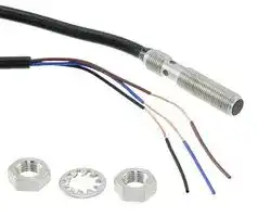
Inductive Proximity Sensor, Cylindrical, E2E Series, M5, 1.2 mm, PNP-NO, 10 V to 30 V, Pre-wired
- Manufacturer: OMRON INDUSTRIAL AUTOMATION
- Product type: Inductive Proximity Sensors
- Sensing Range Max:1.2mm; Thread Size - Metric:M5; Sensor Output:PNP; Supply Voltage DC Min:10V; Supply Voltage DC Max:30V; Product Range:E2E Series; SVHC:No SVHC (20-Jun-2016)
- IP Rating: IP67
- Sensor Type: Inductive
- Product Range: E2E Series
- Sensor Terminals: Cable
- Sensing Range Max: 1.2mm
- Sensor Output Type: 3-Wire, PNP, NO
- Supply Voltage Max: 30VDC
- Supply Voltage Min: 10VDC
- Sensing Distance Max: -
- Sensing Distance Min: -
- Sensing Distance Nom: 1.2mm
- Sensor Body Material: Stainless Steel
- Thread Size - Metric: M5
- Sensor Case / Package: -
- Supply Voltage DC Max: 30V
- Supply Voltage DC Min: 10V
- Operating Temperature Max: 70°C
- Operating Temperature Min: -25°C
| Delivery and price | |
|---|---|
| Units per pack | 50 |
| Price | 44.85 € |
| Current stock | 25+ |
| Lead time | 30 days |
**Small-diameter Proximity Sensor E2E**

## **Ultra small size and simple installation**

- 104 model variations available.

- Improved sensing ranges for easy sensor positioning adjustment.

- High-speed response frequency stably detects moving objects: 5 kHz max.

- Four output LEDs for highly visible status indication.

- Special mounting brackets for reduced installation time.

- Stainless-steel Spiral Tube to protect against cable breakage is available (M4, M5 only).

- When the 4-dia. shielded model is used.

Refer to _Safety Precautions_ on page 10.

For the most recent information on models that have been certified for safety standards, refer to your OMRON website.

## **Features**

## **Lineup of global small-diameter proximity sensors (3 dia., 4 dia., 6.5 dia., M4, M5)**

• A lineup of unshielded models for long distance sensing is also available. Stable long distance sensing performance enables worry-free use.

## **Bright operation indicators make it easy to view sensor status**

   - **Low current consumption: 10mA max** • Current consumption is 2/3 that of conventional small diameter proximity sensors.

- Four indicator LEDs in a 360 degree layout are easily seen from all angles.

## **Protective Stainless-steel Spiral Tubes available**

- Lineup of protective tubes for M4 and M5 sizes. Reduces wire breakage due to snagging or impact.

## **High-speed response enables sharp detection timing**

- 5 kHz response frequency max.

## **Protection circuits prevent failures due to wiring mistakes.**

- Load short-circuit protection and output reverse polarity protection circuits are incorporated.

**1**

**E2E**

## **E2E (Small Diameter) Model Number Legend**

||||||
|---|---|---|---|---|
|**No.**|**Classification**|**Code**||**Meaning**|
||Housing material and shape|S||SUS, threaded|
|||C||SUS, cylindrical|
||Size|03||Outer diameter 3 mm|
|||04||Outer diameter 4 mm|
|||05||Outer diameter 5 mm|
|||06||Outer diameter 6.5 mm|
||Shielding|S||Shielded Models|
|||N||Unshielded Models|
||Sensingdistance|Number||R8: 0.8 mm, 12: 1.2 mm, 02: 2 mm, 03: 3 mm, 04: 4 mm|
||Connection method|WC||PVC Pre-wired Model|
|||MC||M8 Connector, 3-pin|
|||CJ||M8 Pre-wired Connector, 3-pin|
||Output specifications|B||DC 3-wire PNP open-collector output|
|||C||DC 3-wire NPN open-collector output|
||Operation mode|1||Normallyopen (NO)|
|||2||Normallyclosed (NC)|
||Cable length|Blank||Connector Models|
|||Number M||Cable length (Unit: m)<br>(Applicable to Pre-wired Models 2M and Pre-wired Connector Models 0.3M)|


**Note:** The purpose of this model number legend is to provide an understanding of the model numbers and how they correlate to sensor specifications. Models are not available for all combinations of code numbers.

**2**

**E2E**

## **Ordering Information**

## **Proximity Sensors**

**Shielded Models [Refer to** _**Dimensions**_ **on page 12.]**

|**E2E**<br>**Ordering Information**<br>**Proximity Sensors**<br>**Shielded Models[Refer to****_Dimensions_ on page 12.]**|**E2E**<br>**Ordering Information**<br>**Proximity Sensors**<br>**Shielded Models[Refer to****_Dimensions_ on page 12.]**|**E2E**<br>**Ordering Information**<br>**Proximity Sensors**<br>**Shielded Models[Refer to****_Dimensions_ on page 12.]**|**E2E**<br>**Ordering Information**<br>**Proximity Sensors**<br>**Shielded Models[Refer to****_Dimensions_ on page 12.]**|**E2E**<br>**Ordering Information**<br>**Proximity Sensors**<br>**Shielded Models[Refer to****_Dimensions_ on page 12.]**|**E2E**<br>**Ordering Information**<br>**Proximity Sensors**<br>**Shielded Models[Refer to****_Dimensions_ on page 12.]**|**E2E**<br>**Ordering Information**<br>**Proximity Sensors**<br>**Shielded Models[Refer to****_Dimensions_ on page 12.]**|
|---|---|---|---|---|---|---|
||||||||
|**Appearance**|**Sensing**<br>**distance**|**Connection**<br>**method**|**Cable**<br>**specifications**|**Operation**<br>**mode**|**Wire color /**<br>**Pin arrangement**|<br>**Model**<br>**NPN output**<br>**PNP output**<br>**E2E-C03SR8-WC-C1 2M**<br>**E2E-C03SR8-WC-B1 2M**<br>**E2E-C03SR8-WC-C2 2M**<br>**E2E-C03SR8-WC-B2 2M**<br>**E2E-C03SR8-CJ-C1 0.3M**<br>**E2E-C03SR8-CJ-B1 0.3M**<br>**E2E-C03SR8-CJ-C2 0.3M**<br>**E2E-C03SR8-CJ-B2 0.3M**<br>**E2E-C04S12-WC-C1 2M**<br>**E2E-C04S12-WC-B1 2M**<br>**E2E-C04S12-WC-C2 2M**<br>**E2E-C04S12-WC-B2 2M**<br>**E2E-C04S12-CJ-C1 0.3M**<br>**E2E-C04S12-CJ-B1 0.3M**<br>**E2E-C04S12-CJ-C2 0.3M**<br>**E2E-C04S12-CJ-B2 0.3M**<br>**E2E-C04S12-MC-C1**<br>**E2E-C04S12-MC-B1**<br>**E2E-C04S12-MC-C2**<br>**E2E-C04S12-MC-B2**<br>**E2E-C06S02-WC-C1 2M**<br>**E2E-C06S02-WC-B1 2M**<br>**E2E-C06S02-WC-C2 2M**<br>**E2E-C06S02-WC-B2 2M**<br>**E2E-C06S02-CJ-C1 0.3M**<br>**E2E-C06S02-CJ-B1 0.3M**<br>**E2E-C06S02-CJ-C2 0.3M**<br>**E2E-C06S02-CJ-B2 0.3M**<br>**E2E-C06S02-MC-C1**<br>**E2E-C06S02-MC-B1**<br>**E2E-C06S02-MC-C2**<br>**E2E-C06S02-MC-B2**<br>**E2E-S04SR8-WC-C1 2M**<br>**E2E-S04SR8-WC-B1 2M**<br>**E2E-S04SR8-WC-C2 2M**<br>**E2E-S04SR8-WC-B2 2M**<br>**E2E-S04SR8-CJ-C1 0.3M**<br>**E2E-S04SR8-CJ-B1 0.3M**<br>**E2E-S04SR8-CJ-C2 0.3M**<br>**E2E-S04SR8-CJ-B2 0.3M**<br>**E2E-S05S12-WC-C1 2M**<br>**E2E-S05S12-WC-B1 2M**<br>**E2E-S05S12-WC-C2 2M**<br>**E2E-S05S12-WC-B2 2M**<br>**E2E-S05S12-CJ-C1 0.3M**<br>**E2E-S05S12-CJ-B1 0.3M**<br>**E2E-S05S12-CJ-C2 0.3M**<br>**E2E-S05S12-CJ-B2 0.3M**<br>**E2E-S05S12-MC-C1**<br>**E2E-S05S12-MC-B1**<br>**E2E-S05S12-MC-C2**<br>**E2E-S05S12-MC-B2**|
|||||||<br>**NPN output**|
|3 dia.|**0.8mm**|Pre-wired Models<br>(2 m)|PVC<br>(oil-resistant)|NO|Brown: +V<br>Black: Output<br>Blue: 0 V|**E2E-C03SR8-WC-C1 2M**|
|||||NC||**E2E-C03SR8-WC-C2 2M**|
|||M8 Pre-wired<br>Connector Models<br>(0.3 m)|PVC<br>(oil-resistant)|NO|1: +V,<br>3: 0 V,<br>4: Output|**E2E-C03SR8-CJ-C1 0.3M**|
|||||NC||**E2E-C03SR8-CJ-C2 0.3M**|
|4 dia.|**1.2mm**|Pre-wired Models<br>(2 m)|PVC<br>(oil-resistant)|NO|Brown: +V<br>Black: Output<br>Blue: 0 V|**E2E-C04S12-WC-C1 2M**|
|||||NC||**E2E-C04S12-WC-C2 2M**|
|||M8 Pre-wired<br>Connector Models<br>(0.3 m)|PVC<br>(oil-resistant)|NO|1: +V,<br>3: 0 V,<br>4: Output|**E2E-C04S12-CJ-C1 0.3M**|
|||||NC||**E2E-C04S12-CJ-C2 0.3M**|
|||M8 Connector<br>Models|---|NO||**E2E-C04S12-MC-C1**|
|||||NC||**E2E-C04S12-MC-C2**|
|6.5 dia.|**2mm**|Pre-wired Models<br>(2 m)|PVC<br>(oil-resistant)|NO|Brown: +V<br>Black: Output<br>Blue: 0 V|**E2E-C06S02-WC-C1 2M**|
|||||NC||**E2E-C06S02-WC-C2 2M**|
|||M8 Pre-wired<br>Connector Models<br>(0.3 m)|PVC<br>(oil-resistant)|NO|1: +V,<br>3: 0 V,<br>4: Output|**E2E-C06S02-CJ-C1 0.3M**|
|||||NC||**E2E-C06S02-CJ-C2 0.3M**|
|||M8 Connector<br>Models|---|NO||**E2E-C06S02-MC-C1**|
|||||NC||**E2E-C06S02-MC-C2**|
|M4|**0.8mm**|Pre-wired Models<br>(2 m)|PVC<br>(oil-resistant)|NO|Brown: +V<br>Black: Output<br>Blue: 0 V|**E2E-S04SR8-WC-C1 2M**|
|||||NC||**E2E-S04SR8-WC-C2 2M**|
|||M8 Pre-wired<br>Connector Models<br>(0.3 m)|PVC<br>(oil-resistant)|NO|1: +V,<br>3: 0 V,<br>4: Output|**E2E-S04SR8-CJ-C1 0.3M**|
|||||NC||**E2E-S04SR8-CJ-C2 0.3M**|
|M5|**1.2mm**|Pre-wired Models<br>(2 m)|PVC<br>(oil-resistant)|NO|Brown: +V<br>Black: Output<br>Blue: 0 V|**E2E-S05S12-WC-C1 2M**|
|||||NC||**E2E-S05S12-WC-C2 2M**|
|||M8 Pre-wired<br>Connector Models<br>(0.3 m)|PVC<br>(oil-resistant)|NO|1: +V,<br>3: 0 V,<br>4: Output|**E2E-S05S12-CJ-C1 0.3M**|
|||||NC||**E2E-S05S12-CJ-C2 0.3M**|
|||M8 Connector<br>Models|---|NO||**E2E-S05S12-MC-C1**|
|||||NC||**E2E-S05S12-MC-C2**|


**3**

**E2E**

**Unshielded Models [Refer to** _**Dimensions**_ **on page 13.]**

|**Unshielded Models[Refer to****_Dimensions_ on ae 13]**|**Unshielded Models[Refer to****_Dimensions_ on ae 13]**|**Unshielded Models[Refer to****_Dimensions_ on ae 13]**|**Unshielded Models[Refer to****_Dimensions_ on ae 13]**|**Unshielded Models[Refer to****_Dimensions_ on ae 13]**|**Unshielded Models[Refer to****_Dimensions_ on ae 13]**|**Unshielded Models[Refer to****_Dimensions_ on ae 13]**|**Unshielded Models[Refer to****_Dimensions_ on ae 13]**|**Unshielded Models[Refer to****_Dimensions_ on ae 13]**|**Unshielded Models[Refer to****_Dimensions_ on ae 13]**|
|---|---|---|---|---|---|---|---|---|---|
|**pg .**||||||||||
|||||||||||
|||||||||||
|**Appearance**|||**Sensing**<br>**distance**|**Connection**<br>**method**|**Cable**<br>**specifications**|**Operation**<br>**mode**|**Wire color /**<br>**Pin arrangement**|**Model**||
|||||||||**NPN output**|**PNP output**|
|3 dia.|||**2mm**|Pre-wired Models<br>(2 m)|PVC<br>(oil-resistant)|NO|Brown: +V<br>Black: Output<br>Blue: 0 V|**E2E-C03N02-WC-C1 2M**|**E2E-C03N02-WC-B1 2M**|
|||||||NC||**E2E-C03N02-WC-C2 2M**|**E2E-C03N02-WC-B2 2M**|
|||||M8 Pre-wired<br>Connector Models<br>(0.3 m)|PVC<br>(oil-resistant)|NO|1: +V,<br>3: 0 V,<br>4: Output|**E2E-C03N02-CJ-C1 2M**|**E2E-C03N02-CJ-B1 2M**|
|||||||NC||**E2E-C03N02-CJ-C2 2M**|**E2E-C03N02-CJ-B2 2M**|
|4 dia.|||**3mm**|Pre-wired Models<br>(2 m)|PVC<br>(oil-resistant)|NO|Brown: +V<br>Black: Output<br>Blue: 0 V|**E2E-C04N03-WC-C1 2M**|**E2E-C04N03-WC-B1 2M**|
|||||||NC||**E2E-C04N03-WC-C2 2M**|**E2E-C04N03-WC-B2 2M**|
|||||M8 Pre-wired<br>Connector Models<br>(0.3 m)|PVC<br>(oil-resistant)|NO|1: +V,<br>3: 0 V,<br>4: Output|**E2E-C04N03-CJ-C1 0.3M**|**E2E-C04N03-CJ-B1 0.3M**|
|||||||NC||**E2E-C04N03-CJ-C2 0.3M**|**E2E-C04N03-CJ-B2 0.3M**|
|||||M8 Connector<br>Models|---|NO||**E2E-C04N03-MC-C1**|**E2E-C04N03-MC-B1**|
|||||||NC||**E2E-C04N03-MC-C2**|**E2E-C04N03-MC-B2**|
|6.5 dia.|||**4mm**|Pre-wired Models<br>(2 m)|PVC<br>(oil-resistant)|NO|Brown: +V<br>|**E2E-C06N04-WC-C1 2M**|**E2E-C06N04-WC-B1 2M**|
|||||||NC|Black: Output<br>Blue: 0 V|**E2E-C06N04-WC-C2 2M**|**E2E-C06N04-WC-B2 2M**|
|||||M8 Pre-wired<br>Connector Models<br>(0.3 m)|PVC<br>(oil-resistant)|NO|1: +V,<br>3: 0 V,<br>4: Output|**E2E-C06N04-CJ-C1 0.3M**|**E2E-C06N04-CJ-B1 0.3M**|
|||||||NC||**E2E-C06N04-CJ-C2 0.3M**|**E2E-C06N04-CJ-B2 0.3M**|
|||||M8 Connector<br>Models|---|NO||**E2E-C06N04-MC-C1**|**E2E-C06N04-MC-B1**|
|||||||NC||**E2E-C06N04-MC-C2**|**E2E-C06N04-MC-B2**|
|M4|||**2mm**|Pre-wired Models<br>(2 m)|PVC<br>(oil-resistant)|NO|Brown: +V<br>Black: Output<br>Blue: 0 V|**E2E-S04N02-WC-C1 2M**|**E2E-S04N02-WC-B1 2M**|
|||||||NC||**E2E-S04N02-WC-C2 2M**|**E2E-S04N02-WC-B2 2M**|
|||||M8 Pre-wired<br>Connector Models<br>(0.3 m)|PVC<br>(oil-resistant)|NO|1: +V,<br>3: 0 V,<br>4: Output|**E2E-S04N02-CJ-C1 2M**|**E2E-S04N02-CJ-B1 2M**|
|||||||NC||**E2E-S04N02-CJ-C2 2M**|**E2E-S04N02-CJ-B2 2M**|
|M5|||**3mm**|Pre-wired Models<br>(2 m)|PVC<br>(oil-resistant)|NO|Brown: +V<br>|**E2E-S05N03-WC-C1 2M**|**E2E-S05N03-WC-B1 2M**|
|||||||NC|Black: Output<br>Blue: 0 V|**E2E-S05N03-WC-C2 2M**|**E2E-S05N03-WC-B2 2M**|
|||||M8 Pre-wired<br>Connector Models<br>(0.3 m)|PVC<br>(oil-resistant)|NO|1: +V,<br>3: 0 V,<br>4: Output|**E2E-S05N03-CJ-C1 0.3M**|**E2E-S05N03-CJ-B1 0.3M**|
|||||||NC||**E2E-S05N03-CJ-C2 0.3M**|**E2E-S05N03-CJ-B2 0.3M**|
|||||M8 Connector<br>Models|---|NO||**E2E-S05N03-MC-C1**|**E2E-S05N03-MC-B1**|
|||||||NC||**E2E-S05N03-MC-C2**|**E2E-S05N03-MC-B2**|


**4**

## Accessories (Sold separately)

## Mounting Brackets

A Mounting Bracket is not provided with the Sensor ~~.~~ It must be ordered separately as required ~~.~~ [Refer to Dimensions on page 15 ~~.]~~

**==> picture [452 x 509] intentionally omitted <==**

**----- Start of picture text -----**<br>
|||||||||||||||||||
|---|---|---|---|---|---|---|---|---|---|---|---|---|---|---|---|---|---|
|Appearance|||Model —|Quantity|Remarks|
|SS|Y92E|-|SC03|1|Mounting block for 3 dia., M3 x P0.5 screws: 2 pieces|
|\?|
|\7|Y92E-SC04|Mounting|block for 4 dia., M3 x PO.5 screws: 2 pieces|
|<>|Y92E|-|SC06|1|Mounting|block for 6 dia., M3 x|P0O.5 screws: 2 pieces|
|SZ|
|SS|.|
|[>|Y92E-SS04|1|L-shaped|Mounting|Bracket for M4 screws|
|INS|.|
|[>|Y92E-SS05|1|L-shaped Mounting|Bracket for M5 screws|
|Nut|Set|(Sold|separately)|
|Applicable sensor|outer|
|Clamping|nuts:|2|pieces,|toothed|washer:|1|piece|
|Protective|Stainless|-s|teel|Spiral|Tube|against|Wire|Breakage|(Sold|separately)|
|A|Spiral|Tube|is|not|provided|with|the|Sensor|.|It|must|be|ordered|separately|as|required|.|
|[Refer|to|Dimensions on on|page|15|.]|
|Applicable sensor|outer|
|Y92E|-|STS04|-0|5|0.5m|
|M4|
|Y92E|-|STS04|-|10|im|
|Y92E|-|STS05|-|05|0.5m|
|M5|
|Y92E|-|STS05|-|10|1m|
|Sensor|I/O|Connector|(Socket|on|One|Cable|End)|
|A|Sensor|I/O|Connector|is|not|provided|with|the|Sensor|.|It|must|be ordered|separately|as|required|.|
|[Refer|to|Dimensions on|page|16|.]|
|ize|Cable|Number|of|cable|Straight|Right-angle|
|specifications|wires (conductors)|Sasi Sn)|Model|
|XS3|F-|M8PVC3S2M|XS3|F-|M8PVC3A2M|
|v8|PVC|3|
|XS3|F-|M8PVC3S5M|XS3|F-|MBPVC3A5M|

**----- End of picture text -----**<br>


Protective Stainless ~~-s~~ teel Spiral Tube against Wire Breakage (Sold separately) A Spiral Tube is not provided with the Sensor ~~.~~ It must be ordered separately as required ~~.~~ [Refer to Dimensions on on page 15 ~~.]~~

**E2E**

## **Ratings and Specifications**

|**Size**|**Size**|**Size**|**3 dia.**|**3 dia.**|**3 dia.**|**3 dia.**|**3 dia.**|**3 dia.**|**4 dia.**|**4 dia.**|**4 dia.**|**4 dia.**|**4 dia.**|**4 dia.**|**6.5 dia.**|**6.5 dia.**|**6.5 dia.**|**6.5 dia.**|**6.5 dia.**|**6.5 dia.**|**M4**|**M4**|**M4**|**M4**|**M4**|**M5**|**M5**|**M5**|**M5**|**M5**|**M5**|
|---|---|---|---|---|---|---|---|---|---|---|---|---|---|---|---|---|---|---|---|---|---|---|---|---|---|---|---|---|---|---|---|
|**Type**|||**Shielded**|||**Unshielded**|||**Shielded**|||**Unshielded**|||**Shielded**|||**Unshielded**|||**Shielded**||**Unshielded**|||**Shielded**|||**Unshielded**|||
|**Item**<br>**Model**|||**E2E-C03SR8**|||**E2E-C03N02**|||**E2E-C04S12**|||**E2E-C04N03**|||**E2E-C06S02**|||**E2E-C06N04**|||**E2E-S04SR8**||**E2E-S04N02**|||**E2E-S05S12**|||**E2E-S05N03**|||
|**Sensing distance**<br>**(at 23**°**C)**|||0.8 mm±10%|||2 mm±10%|||1.2 mm±10%|||3 mm±10%|||2 mm±10%|||4 mm±10%|||0.8 mm±10%||2 mm±10%|||1.2 mm±10%|||3 mm±10%|||
|**Setting distance*1**<br>**(Sensing distance × 0.7)**|||0 to 0.56 mm|||0 to 1.4 mm|||0 to 0.84 mm|||0 to 2.1 mm|||0 to 1.4 mm|||0 to 2.8 mm|||0 to 0.56 mm||0 to 1.4 mm|||0 to 0.84 mm|||0 to 2.1 mm|||
|**Differential travel**|||15% max. of sensingdistance|||||||||||||||||||||||||||||
|**Detectable object**|||Ferrous metal(The sensingdistance decreases with non-ferrous metal. Refer to_Engineering Data_onpage 7.)|||||||||||||||||||||||||||||
|**Standard sensing**<br>**object**|||Iron,<br>3 × 3 × 1 mm|||Iron,<br>6 × 6 × 1 mm|||Iron,<br>4 × 4 × 1 mm|||Iron,<br>9 × 9 × 1 mm|||Iron,<br>6.5×6.5×1 mm|||Iron,<br>12×12×1 mm|||Iron,<br>3 × 3 × 1 mm||Iron,<br>6 × 6 × 1 mm|||Iron,<br>4 × 4 × 1 mm|||Iron,<br>9 × 9 × 1 mm|||
|**Response frequency**|||5 kHz|||3.5 kHz|||4 kHz|||2 kHz|||3 kHz|||3 kHz|||5 kHz||3.5 kHz|||4 kHz|||2 kHz|||
|**Power supply voltage**<br>***2**|||10 to 30 VDC (including 10% ripple (p-p))|||||||||||||||||||||||||||||
|**Current**|**consumption**||10 mA max.|||||||||||||||||||||||||||||
|**Control**<br>**output**<br>***3**|**Load current**||50 mA max.||||||100 mA max.||||||200 mA max.<br>(60 to 70°C: 100 mA)||||||50 mA max.|||||100 mA max.||||||
||**Residual**<br>**voltage**||2 V max.*5|||||||||||||||||||||||||||||
|**Indicato**|**rs**||Operation indicator: Yellow(complies with European standard EN60947-5-2)Lights duringoutput.|||||||||||||||||||||||||||||
|**Operation mode**<br>**(with sensing object**<br>**approaching)**|||B1/B2: PNP open collector, C1/C2: NPN open collector<br>B1/C1 models: NO, B2/C2 models: NC|||||||||||||||||||||||||||||
|**Protection circuits**|||Output reversepolarity protection, Power source circuit reversepolarity protection, Surge suppressor, Load short-circitprotection|||||||||||||||||||||||||||||
|**Ambient**<br>**temperature range**|||Operation and storage: −25 to 70°C (with no ice or condensation)|||||||||||||||||||||||||||||
|**Ambient**<br>**humidity range**|||Operation and storage: 35% to 95% (with no condensation)|||||||||||||||||||||||||||||
|**Temperature**<br>**influence**|||15% max. of sensing distance at 23°C within temperature range of −25 to 70°C|||||||||||||||||||||||||||||
|**Voltage in**||**fluence**|2.5% max. of sensingdistance at rated voltage in the rated voltage<br>15% range|||||||||||||||||||||||||||||
|**Insulation**||**resistance**|50 M<br>min.(at 500 VDC)between current-carrying parts and case|||||||||||||||||||||||||||||
|**Dielectric**||**strength**|500 VAC, 50/60 Hz for 1 minute between current-carrying parts and case|||||||||||||||||||||||||||||
|**Vibration**||**resistance**|Destruction: 10 to 55 Hz, 1.5-mm double amplitude for 2 hours each in X, Y, and Z directions|||||||||||||||||||||||||||||
|**Shock res**||**istance**|Destruction: 500 m/s210 times each in X, Y, and Z directions|||||||||||||||||||||||||||||
|**Degree of**||**protection**|IEC 60529 IP67, in-house standards: oil-resistant*****6|||||||||||||||||||||||||||||
|**Connecting**<br>**method**||**Pre-wired**<br>**Models**|Yes||||||Yes||||||Yes||||||Yes|||||Yes||||||
|||**M8 Pre-wired**<br>**Connector**<br>**Models**|Yes||||||Yes||||||Yes||||||Yes|||||Yes||||||
|||**M8 Connector**<br>**Models**|<br>No||||||Yes||||||Yes||||||No|||||Yes||||||
|**Weight**<br>**(packed**<br>**state)**||**Pre-wired**<br>**Models**|Approx. 25 g|||Approx. 30 g|||Approx. 35 g|||Approx. 35 g|||Approx. 55 g|||Approx. 55 g|||Approx. 30 g||Approx. 30 g|||Approx. 35 g|||Approx. 40 g|||
|||**M8 Pre-wired**<br>**Connector**<br>**Models**|Approx. 20 g|||Approx. 20 g|||Approx. 15 g|||Approx. 20 g|||Approx. 20 g|||Approx. 25 g|||Approx. 20 g||Approx. 20 g|||Approx. 20 g|||Approx. 20 g|||
|||**M8 Connector**<br>**Models**|<br>---|||---|||Approx. 10 g|||Approx. 10 g|||Approx. 10 g|||Approx. 15 g|||---||---|||Approx. 15 g|||Approx. 15 g|||
|**Materials**||**Case**|SUS303(EN1.4305*7)|||||||||||||||||||||||||||||
|||**Sensing**<br>**surface**|Heat-resistant ABS|||||||||||||||||||||||||||||
|||**Clamping**<br>**nuts*4**|No||||||||||||||||||SUS430 (EN1.4016*****7)|||||||||||
|||**Toothed**<br>**washer*4**|No||||||||||||||||||SUS303 (EN1.4305*****7)|||||||||||
|||**Cable**|PVC|||||||||||||||||||||||||||||
|**Accessories**||**Instruction**<br>**manual**|Yes|||||||||||||||||||||||||||||
|||**Model label**<br>|Yes|||||||||||||||||||||||||||||
|||**Mounting**<br>**brackets**|Sold separately|||||||||||||||||||||||||||||


- *1. Operating within the set distance enables high-speed responsiveness and a more stable repeat accuracy.

- *2. When used with a 12 V power source, the Sensor is less susceptible to the effects of internal heat generation. Therefore a more stable repeat accuracy can be obtained.

- *3. When the control output is 20 mA or less, the Sensor is less susceptible to the effects of internal heat generation. Therefore a more stable repeat accuracy can be obtained.

- *4. Nuts: 2 pieces, toothed washer: 1 piece

- *5. 3 dia., M4: load current 50 mA, cable length 2 m

   - 4 dia., M5: load current 100 mA, cable length 2 m

   - 6.5 dia.: load current 200 mA, cord length 2 m

- *6. Oil resistance in-house standard: Performance with respect to water insoluble oil. (Test at right)

- *7. Material name in EN standards.

Oil resistance test

After the test time elapses, the characteristics below are checked for problems.

Test oil: Water insoluble oil (1) Visual appearance (no damage that Velocite No. 3 affects product characteristics) 50°C × 250 hours (2) Operation check (ON/OFF) Depth 10 cm (3) Insulation resistance (50 M min. at 500 VDC)

- (4) Dielectric strength (500 VAC, 1 min.)

Sensor

- (5) Water resistance (IP67)

**6**

**==> picture [483 x 377] intentionally omitted <==**

**==> picture [139 x 147] intentionally omitted <==**

**==> picture [310 x 136] intentionally omitted <==**

**==> picture [49 x 32] intentionally omitted <==**

**E2E**

## **Distance - Horizontal Repeat Accuracy**

**==> picture [477 x 329] intentionally omitted <==**

**----- Start of picture text -----**<br>
Shielded Models<br>E2E-C03SR8 /E2E-S04SR8 E2E-C04S12 /E2E-S05S12 E2E-C06S02<br>0.8 1.2 2<br>12 VDC 12 VDC<br>0.7 24 VDC 1.8 12 VDC 24 VDC<br>24 VDC 1<br>1.6<br>0.6<br>1.4<br>0.8<br>0.5<br>1.2<br>0.4 0.6 1<br>0.3 3 × 1 mmX ON point repeat accuracy 0.4 4 × 1 mmX ON point repeat accuracy 0.80.6 6.5 × 1 mmX ON point repeat accuracy<br>0.2<br>0.4<br>0.2<br>0.1<br>0.2<br>0  0.05  0.1  0.15  0.2 0  0.05  0.1  0.15  0.2 0  0.05  0.1  0.15  0.2<br>Repeat accuracy (mm) Repeat accuracy (mm) Repeat accuracy (mm)<br>Unshielded Models<br>E2E-C03N02 /E2E-S04N02 E2E-C04N03 /E2E-S05N03 E2E-C06N04<br>2 3 4<br>1.8 12 VDC 24 VDC 12 VDC 24 VDC 3.5 12 VDC 24 VDC<br>2.5<br>1.6<br>3<br>1.4<br>2<br>1.2 2.5<br>1 1.5 2<br>0.80.6 6 × 1 mmX ON point repeat accuracy 1 9 × 1 mmX ON point repeat accuracy 1.5 12 × 1 mmX ON point repeat accuracy<br>1<br>0.4<br>0.5<br>0.5<br>0.2<br>0  0.1  0.2  0.3  0.4  0.5 0  0.1  0.2  0.3  0.4  0.5 0  0.1  0.2  0.3  0.4  0.5<br>Repeat accuracy (mm) Repeat accuracy (mm) Repeat accuracy (mm)<br>Distance X (mm) Distance X (mm) Distance X (mm)<br>Distance X (mm) Distance X (mm) Distance X (mm)<br>**----- End of picture text -----**<br>


## **Sensing distance vs. repeat accuracy graphs**

By operating within the sensor installation distance, the repeat accuracy stabilizes. This is reference data based on a standard sensing object, and is not a guarantee of performance. The repeat accuracy varies depending on the effects of temperature, the material and surface condition of the sensing object, and other conditions.

## **Minimum measurement gap**

|**Model**|**Minimum gap (mm)**|
|---|---|
|E2E-C03S/S04S<br>|0.3|
|E2E-C03N/S04N<br>|0.6|
|E2E-C04S/S05S<br>|0.4|
|E2E-C04N/S05N<br>|0.9|
|E2E-C06S<br>|0.6|
|E2E-C06N<br>|1.2|


**Note:** Measured at constant temperature of 23ºC using an iron sensing object of size at least as large as standard sensing object (see right).

**==> picture [131 x 101] intentionally omitted <==**

**----- Start of picture text -----**<br>
Size of test piece<br>gap<br>30 mm<br>15 mm<br>30 mm Material: Iron<br>**----- End of picture text -----**<br>


**8**

**==> picture [479 x 44] intentionally omitted <==**

**==> picture [74 x 33] intentionally omitted <==**

**==> picture [97 x 62] intentionally omitted <==**

**==> picture [74 x 33] intentionally omitted <==**

**==> picture [97 x 62] intentionally omitted <==**

**==> picture [121 x 74] intentionally omitted <==**

**==> picture [70 x 52] intentionally omitted <==**

**==> picture [121 x 75] intentionally omitted <==**

**==> picture [70 x 52] intentionally omitted <==**

**Connector Cable Pin Arrangement**

**==> picture [49 x 32] intentionally omitted <==**

**==> picture [484 x 629] intentionally omitted <==**

**==> picture [49 x 32] intentionally omitted <==**

**E2E**

## **Mounting**

## **Tightening Force**

**Mounting threaded models (E2E-S )** Do not tighten the nut with excessive force. A washer must be used with the nut.

Tr

## **High-speed responsiveness**

To obtain a better high-speed response, it is recommended that you use the sensor at about 50% of the possible sensing distance. A high-speed response may not be obtained with some sensing object surfaces, materials, and shapes, or when the sensing distance is greater than the set distance.

For the effects of materials, refer to _Engineering Data_ on page 7.

## **Repeated cable bending tolerance**

If you require repeated bending tolerance, use the Connector Model together with a connector cable that is specified for bending tolerance.

|**Note: 1.**<br>Only use the provided nut and toothed washer.<br>Risk of changes in the sensing distance and damage if a different<br>material is used. If you lose the nut or washer, purchase an optional nut<br>set.<br>**2.** The following strengths assume washers are being used.|**Note: 1.**<br>Only use the provided nut and toothed washer.<br>Risk of changes in the sensing distance and damage if a different<br>material is used. If you lose the nut or washer, purchase an optional nut<br>set.<br>**2.** The following strengths assume washers are being used.|**Note: 1.**<br>Only use the provided nut and toothed washer.<br>Risk of changes in the sensing distance and damage if a different<br>material is used. If you lose the nut or washer, purchase an optional nut<br>set.<br>**2.** The following strengths assume washers are being used.|**Note: 1.**<br>Only use the provided nut and toothed washer.<br>Risk of changes in the sensing distance and damage if a different<br>material is used. If you lose the nut or washer, purchase an optional nut<br>set.<br>**2.** The following strengths assume washers are being used.|**Note: 1.**<br>Only use the provided nut and toothed washer.<br>Risk of changes in the sensing distance and damage if a different<br>material is used. If you lose the nut or washer, purchase an optional nut<br>set.<br>**2.** The following strengths assume washers are being used.|
|---|---|---|---|---|
|**Size**|**M4**||**M5**||
|**Item**|**Shielded**|**Unshielded**|**Shielded**|**Unshielded**|
|**Tr**|0.8 N·m||1 N·m||


**Note:** Only use the provided nut.

**Mounting unthreaded cylindrical models (E2E-C )**

- ~~L~~ Dimpled end of set screw (M3) (Screw not provided)

**==> picture [70 x 48] intentionally omitted <==**

|**Size**|**3 dia.**|**3 dia.**|**4 dia.**|**4 dia.**|**6.5 dia.**|**6.5 dia.**|
|---|---|---|---|---|---|---|
|**Item**|**Shielded**|**Unshielded**|**Shielded**|**Unshielded**|**Shielded**|**Unshielded**|
|**L***|9 to 21<br>mm|15 to 27<br>mm|8 to 21<br>mm|14 to 27<br>mm|12 to 26 mm||
|**Torque**|0.2 N·m max.||||0.4 N·m max.||


* Excluding the operation indicator area.

When using a set screw, tighten it to the torque indicated in the table above.

## **Oil resistance**

Refer to _Sensor I/O Connector_ on page 5.

## **Protective Stainless-steel Spiral Tube**

The spiral tube is in a fixed state and is intended to provide protection against wire breakage due to shock from tools or other objects. If you require repeated bending tolerance, use the Connector Model together with a connector cable that is specified for bending tolerance.

Refer to _Sensor I/O Connector_ on page 5.

## **Block type mounting accessories**

Due to differences in dimensional tolerances, these cannot be used with older small diameter proximity sensors. (E2E-CR6, E2E-CR8)

## **Bending radius for mounting**

If the cable is bent from its base, the resin on the surface of the cable may peel off, however, this will not affect the protective structure or sensing performance.

Avoid bending the cable at less than 10 mm from the its base. When bending the cable, refer to the table below.

||**Cable diameter**|**Bending radius**|||10 mm||
|---|---|---|---|---|---|---|
||3 dia., M4<br>4 dia., M5|7 mm<br>9 mm||Sensor||R|
||6.5 dia.|12 mm|||||
||||||||


In accordance with our oil resistance standard, we test oil resistance based on water insoluble oil (complies with test oil based on JIS C0920, Appendix 1).

When water soluble cutting oil is used, durability varies due to the dilution ratio and other factors. Please test oil resistance using the actual oil that will be used.

**11**

**E2E**

(Unit: mm)

Tolerance class IT16 applies to dimensions in this data sheet unless otherwise specified.

## **Dimensions**

## **Sensors**

**==> picture [473 x 305] intentionally omitted <==**

**----- Start of picture text -----**<br>
Pre-wired Models<br>Mounting Hole Dimensions<br>(Shielded)<br>Dimension 3 dia. 4 dia. 6.5 dia. M4 M5<br>F (mm) 3.3 +0.50 4.2 +0.50 7 +0.50 4.5 +0.50 5.5 +0.50<br>F<br>E2E-C03SR8-WC- | E2E-C04S12-WC- |<br>2.4-dia. vinyl-insulated round cable with 3 conductors  2.9-dia. vinyl-insulated round cable with 3 conductors<br>3-0.1 [0] [ dia.] 18 27.1 (Conductor cross section: 0.09 mmInsulator diameter: 0.7 mm), Standard length: 2 m [2] ,  4-0.1 [0] [ dia.] 18.5 25.1 Insulator diameter: 0.8 mm), Standard length: 2 m(Conductor cross section: 0.14 mm [2] ,<br>u Operation indicators (yellow) 4 × 90° y Ee<br>Operation indicators (yellow) 4 × 90°<br>E2E-C06S02-WC- OO E2E-S04SR8-WC- OO<br>6.5-0.1 [0] [ dia.] 24.1 36 18 27.1<br> 8.5 dia. 15.1<br>7 0.6 5 2.4-dia. vinyl-insulated round cable with 3 conductors<br>@=a 3 1 Insulator diameter: 0.7 mm), Standard length: 2 m(Conductor cross section: 0.09 mm [2] ,<br>Operation indicators  4-dia. vinyl-insulated round cable with 3 conductors<br>(yellow) 4 × 90° (Conductor cross section: 0.14 mm [2] ,<br>Insulator diameter: 0.85 mm), Standard length: 2 m<br>©) M4  × 0.5 | HL So Operation indicators (yellow) 4 × 90°<br>Two clamping nuts Toothed washer<br>E2E-S05S12-WC- |<br>25.1<br>18.5<br> 10 dia. 15.1<br>8 0.6 4 2.9-dia. vinyl-insulated round cable with 3 conductors<br>3 1 (Conductor cross section: 0.14 mmInsulator diameter: 0.8 mm), Standard length: 2 m [2] ,<br>M5 ×0.5 Operation indicators (yellow) 4 × 90°<br>Two clamping nuts Toothed washer<br>**----- End of picture text -----**<br>


## **M8 Pre-wired Connector Models (0.3 m) (Shielded)**

**==> picture [447 x 245] intentionally omitted <==**

**----- Start of picture text -----**<br>
E2E-C03SR8-CJ- OO E2E-C04S12-CJ- |<br>3-0.1 [0] [ dia.] 18 27.1 Standard length: 300 mm2.4-dia. vinyl-insulated round cable,  4-0.1 [0] [ dia.] 18.5 25.1 2.9-dia. vinyl-insulated round cable, Standard length: 300 mm<br>v aT | 0 See<br>Operation indicators (yellow) 4 × 90° M8 × 1 Operation indicators (yellow) 4 × 90° M8 × 1<br>E2E-C06S02-CJ- OO E2E-S04SR8-CJ- |<br>36 4-dia. vinyl-insulated round cable,  27.1<br>6.5-0. [0] 1 [ dia.] 24.1 Standard length: 300 mm 18<br>= | _ 8.5 dia. = 15.1<br>6 - TE 7 0.6 3 1 | 5 2.4-dia. vinyl-insulated round cable, Standard length: 300 mm M8 × 1<br>Operation indicators (yellow) 4 × 90° M8 × 1 @ oa TE<br>M4  × 0.5 Operation indicators (yellow) 4 × 90°<br>Two clamping nuts Toothed washer<br>E2E-S05S12-CJ- |<br>25.1<br>18.5<br>10 dia. 15.1<br>8 0.6 4 2.9-dia. vinyl-insulated round cable,<br>3 1 Standard length: 300 mm M8 × 1<br>M5  × 0.5 pd Operation indicators (yellow) 4 × 90° wel<br>Two clamping nuts Toothed washer<br>**----- End of picture text -----**<br>


**12**

**E2E**

## **M8 Connector Models (Shielded)**

**==> picture [422 x 180] intentionally omitted <==**

**----- Start of picture text -----**<br>
E2E-C04S12-MC- OH E2E-C06S02-MC- |<br>40.1 43.5<br>4-0.1 [0] [ dia.] 24.2 4 6.5-0.1 [0]  dia. 28.5<br>18.5 24.1 4<br>anal — =],<br>eres<br>6.75 dia. ||<br>6.75 dia.<br>Operation indicators (yellow) 4 × 90° M8 × 1 Operation indicators (yellow) 4 × 90° M8 × 1<br>E2E-S05S12-MC- OH<br>40.1<br>24.2<br>18.5<br> 10 dia. 15.1<br>0.6 4<br>8 3<br>M5  × 0.5 6.75 dia. M8 × 1<br>Two clamping nuts ‘\ Operation indicators (yellow) 4 × 90°<br>Toothed washer<br>**----- End of picture text -----**<br>


## **Pre-wired Models (Unshielded)**

**Mounting Hole Dimensions**

|**Dimension**<br>**3 dia.**<br>**4 dia.**<br>**6.5 dia.**<br>**M4**<br>**M5**<br>F (mm)<br>3.3<br>4.2<br>7<br>4.5<br>5.5<br>+0.5<br>0<br>+0.5<br>0<br>+0.5<br>0<br>+0.5<br>0<br>+0.5<br>0<br>F<br>~~,a~~|
|---|
|**E2E-C03N02-WC-**<br>**E2E-C04N03-WC-**<br>~~|~~<br>~~|~~|
|~~23.9~~<br>6<br>~~**33**~~<br>**3 0**<br>**-0.1 dia.**<br>2.4-dia. vinyl-insulated round cable with 3 conductors<br>(Conductor cross section: 0.09 mm2,<br>Insulator diameter: 0.7 mm), Standard length: 2 m<br>6<br>24.4<br>~~**31**~~<br>**4 0**<br>**-0.1 dia.**<br>2.9-dia. vinyl-insulated round cable with 3 conductors<br>(Conductor cross section: 0.14 mm2,<br>Insulator diameter: 0.8 mm), Standard length: 2 m<br>~~Y LU.~~<br>~~Y~~|
|Operation indicators (yellow) 4 × 90°<br>Operation indicators (yellow) 4 × 90°|
|6<br>~~**35.9**~~<br>~~24.2~~<br>**6.5 0**<br>**-0.1 dia.**<br>Operation indicators (yellow) 4 × 90°<br>4-dia. vinyl-insulated round cable with 3 conductors<br>(Conductor cross section: 0.14 mm2,<br>Insulator diameter: 0.85 mm), Standard length: 2 m<br>**E2E-C06N04-WC-**<br>6<br>6.5<br>5<br>~~1~~<br>23.9<br>~~**33**~~<br>~~21~~<br>~~7~~<br>8.5 dia.<br>3<br>dia.<br>0<br>-0.1<br>**M4**× 0.5<br>3<br>2.4-dia. vinyl-insulated round cable with 3 conductors<br>(Conductor cross section: 0.09 mm2,<br>Insulator diameter: 0.7 mm), Standard length: 2 m<br>Operation indicators (yellow) 4 × 90°<br>**E2E-S04N02-WC-**<br>~~|~~<br>~~|~~<br>~~am~~<br>~~=e~~<br>~~©)~~ ~~elect~~<br>NF,<br>~~IB~~|
|Two clamping nuts Toothed washer|


**E2E-S05N03-WC-**

~~**31**~~ 24.4 10 dia. ~~21~~ 2.9-dia. vinyl-insulated round cable with 3 conductors 6.5 4 (Conductor cross section: 0.14 mm[2] , ~~8~~ 4-0.10 dia. 6 3 1 Insulator diameter: 0.8 mm), Standard length: 2 m ~~eo Fpl~~ **M5** × 0.5 Operation indicators (yellow) 4 × 90° Two clamping nuts Toothed washer

**13**

**==> picture [258 x 10] intentionally omitted <==**

**----- Start of picture text -----**<br>
M8 Pre - wired Connector Models (0 . 3 mm) (Unshielded)<br>**----- End of picture text -----**<br>


**==> picture [461 x 505] intentionally omitted <==**

**----- Start of picture text -----**<br>
E2E - C03N02 - C J- LU E2E - C04N03 -C J -L 0U<br>33— _ 2.4Standard-dia. vinylength:l-insulated300 mm round cable, 31 2.9Standard-dia. vinylength:l-insulated300 mm round cable,<br>38 , di a . |"6 | 23.9 / 48 ,  dia. aaa<br>Bo Fe amr<br>NE I OF ore TE<br>Operation indicators (yellow) 4 x 90° M8 x 1 Operation indicators (yellow) 4 x 90° M8 x 1<br>E2E - CO6N04 - C J- LU E2E - S04N02 - C J- L0 33<br>f+ 35 . 9 4 -d ia.oviny ol- insulated round cable, 8.5 dia. +—— 23.9<br>o t e 4 2 Standard length: 300 mm id 5 | 2.4-dia. viny -i nsulated round cable,<br>6.5.9 4 dia. _ po e 3 Standard length: 300 mm M8 x 1<br>ee oe | at m | | [ee<br>Ss © Paes [fl<br>Operation indicators (yellow) 4 x 90° M8 x 1 M4 x0.5 Operation indicators (yellow) 4 x 90°<br>Two clamping nuts = Toothed washer<br>E2E - S05N03 -C J -O 00 31<br>10 dia.. + 24.4<br>a<br>65<br>3 4 | 2.9-dia. vinyl-insulated round cable,<br>4 2 , [dia.] (6 S tandard length: 300 mm<br>(oS M5 a x 0.5 HA Operation Paen indicators omo (yellow) r) 4 t| x 90° We |<br>Two clamping nuts = Toothed washer MB x 1<br>M8s Connector Models (Unshielded)<br>”<br>AFi<br>E2E - C04N0 3- M C- L1 E2E - CO6N0 4- M C- L0<br>46. 43. 4<br>+ 30.1 |} 28.4 ——><br>45, dia. ra 24.4 —>| | 4 6.5 2, dia. r e  24.2 ——> ‘<br>8 =potEH aetT||<br>6.75 dia.<br>Operation indicators (yellow) 4 x 90° M8 x1 Operation indicators (yellow) 4 x 90° ore dia. M8 x 1<br>E2E - S05N0 3- M C- OU<br>|; re<br>+ 30.1<br>10 dia. 24.4<br>|}——— 2] ——+|<br>8 5.25 4<br>4 3 .dia. Le .oof W e |Litney<br>M5 x 0.5 Operation indicators (yellow)M8 x4 x1 90°<br>Two clamping nuts Toothed washer<br>**----- End of picture text -----**<br>


**E2E**

## **Accessories**

## **Mounting Brackets**

**==> picture [475 x 357] intentionally omitted <==**

**----- Start of picture text -----**<br>
Y92E-SC03 (3-dia. block) Y92E-SC04 (4-dia. block) Y92E-SC06 (6.5-dia. block)<br>Material: Iron Material: Iron Material: Iron<br>Y92E-SS04 (for M4 screw) Y92E-SS05 (for M5 screw)<br>17<br>17 A 2 2-R1 A 5.1 +0.10  dia. 2<br>4 +0.10 dia.<br>Half punch<br>Half punch<br>20<br>20 14 [±0.1] (R2) 14  [± 0.1] R2<br>Material: Iron A | 1 Material: Iron 5 i: A R 0.3 max. 2.5  [± 0.05] 1<br>5 R 0.3 max. 2.5  [± 0.05]<br>Cross sectional diagram A-A 4 10  [± 0.1] +} 3.5  — Cross sectional diagram A-A<br>10  [± 0.1] 3.5 dia. y dia. 22<br>22 8  [± 0.1]<br>8  [± 0.1]<br>| 2-R1 o<br>Protective Stainless-steel Spiral Tubes (Sold Separately)piral Tubes (Sold Separately)iral Tubes (Sold Separately)(Sold Separately)Sold Separately)parately)arately)y)<br>Y92E-STS04- | Y92E-STS05- oO<br>L L<br>8 dia. A TT A 4 dia. 8 dia. A TT A 4 dia.<br>7 dia. 7 dia.<br>Brass/nickel plating Stainless steel (SUS304) Brass/nickel plating Brass/nickel plating Stainless steel (SUS304) Brass/nickel plating<br>M4 × 0.5 M5 × 0.5<br>5.6 dia. 5.6 dia.<br>12 2 12 2<br>|b 16 -| i 12 |b 16 + L 12<br>L = 0.5 m (Y92E-STS04-05), 1 m (Y92E-STS04-10) L = 0.5 m (Y92E-STS05-05), 1 m (Y92E-STS05-10)<br>**----- End of picture text -----**<br>


## **Protective Stainless-steel Spiral Tubes (Sold Separately)piral Tubes (Sold Separately)iral Tubes (Sold Separately)(Sold Separately)Sold Separately)parately)arately)y)**

**15**

E2E

**==> picture [484 x 246] intentionally omitted <==**

**----- Start of picture text -----**<br>
SensorVOConnectors<br>XS3F - M8PVC3L1LIM _ .<br>Straight<br>|< 31.4<br>4 9 _—,dia.<br>M8x1 J \ 5<br>Brass/nickel plating Soft PBT (UL94V-0) 30 ———-<br>L = 2 m (XS3 F- M8PVC3S2M),<br>5 m (XS3 F- M8PVC3S5M)<br>Righ ggt- angle<br>tt 23.1 Te _<br>20.5 Soft PBT (UL94V -0 ) | . 30 5<br>Brass/nickel plating<br>9 dia.<br>1<br>4<br>(3) L = 2m (XS3 F- M8PVC3A2M),<br>Mea” 5 m (XS3 F- M8PVC3A5M)<br>**----- End of picture text -----**<br>


**==> picture [192 x 57] intentionally omitted <==**

**OMRON AUTOMATION AND SAFETY • THE AMERICAS HEADQUARTERS** • Schaumburg, IL USA • 847.843.7900 • 800.556.6766 • www.omron247.com

**OMRON CANADA, INC. • HEAD OFFICE OMRON ARGENTINA • SALES OFFICE** Toronto, ON, Canada • 416.286.6465 • 866.986.6766 • www.omron247.com Cono Sur • 54.11.4783.5300

**OMRON ELECTRONICS DE MEXICO • HEAD OFFICE OMRON CHILE • SALES OFFICE** México DF • 52.55.59.01.43.00 • 001.800.556.6766 • mela@omron.com Santiago • 56.9.9917.3920 **OMRON ELECTRONICS DE MEXICO • SALES OFFICE OTHER OMRON LATIN AMERICA SALES** Apodaca, N.L. • 52.81.11.56.99.20 • 001.800.556.6766 • mela@omron.com 54.11.4783.5300

**OMRON ELETRÔNICA DO BRASIL LTDA • HEAD OFFICE** São Paulo, SP, Brasil • 55.11.2101.6300 • www.omron.com.br

**OMRON EUROpE B.V. •** Wegalaan 67-69, NL-2132 JD, Hoofddorp, The Netherlands. • Tel: +31 (0) 23 568 13 00 • Fax: +31 (0) 23 568 13 88 • www.industrial.omron.eu

_Authorized Distributor:_

## **Automation Control Systems**

- Machine Automation Controllers (MAC) • Programmable Controllers (PLC)

- Operator interfaces (HMI) • Distributed I/O • Software

## **Drives & Motion Controls**

- Servo & AC Drives • Motion Controllers & Encoders

## **Temperature & process Controllers**

- Single and Multi-loop Controllers

## **Sensors & Vision**

- Proximity Sensors • Photoelectric Sensors • Fiber-Optic Sensors

- Amplified Photomicrosensors • Measurement Sensors

- Ultrasonic Sensors • Vision Sensors • RFID/Code Readers

## **Industrial Components**

- Relays • Pushbuttons & Indicators  • Limit and Basic Switches • Timers

- Counters • Metering Devices • Power Supplies

**Safety**

- Laser Scanners • Safety Mats • Edges and Bumpers

- Programmable Safety Controllers • Light Curtains • Safety Relays

- Safety Interlock Switches

Note: Specifications are subject to change.                          © 2013 Omron Electronics LLC                          Printed in U.S.A.

E55I-E-01

_Printed on recycled paper._
Updated at June 8, 2026
With a legacy spanning over 80 years, Omron Industrial Automation is a globally recognized leader in the manufacture of advanced industrial control and automation components. Renowned for their reliability and engineering excellence, Omron delivers comprehensive solutions that enhance efficiency, machine safety, and precision across a wide range of manufacturing environments. Our extensive portfolio of Omron products is heavily focused on their industry-leading sensing and switching technologies. We offer a vast selection of sensors, excelling specifically in high-performance proximity sensors, light sensors, and temperature sensors. Complementing this range are robust switching solutions, featuring a deep inventory of power relays, solid-state relays, safety relays, and essential relay accessories designed for demanding operational requirements. Beyond sensing and switching, Omron is highly regarded for its precision automation and process control equipment. Our selection features highly accurate temperature controllers, versatile process controllers, and sophisticated panel displays and instrumentation. To support these fundamental systems, we also supply dependable Omron power supplies, notably AC/DC converters, alongside vital connectivity components like DIN rail terminal blocks to ensure secure, efficient, and complete industrial setups.
About Novapart
Novapart is a B2B electronic component broker specialising in stock shortages and cost reduction. We source hard-to-find parts and identify compliant alternatives across a catalogue of 410,000+ components from 500+ manufacturers.
Learn more →Stock Shortage Specialist
When a component is unavailable, discontinued or has an unacceptable lead time, we tap into our network of vetted European and Asian distributors to source what you need — without compromising on quality or traceability.
Request a quote →Compliant Alternatives
We identify pin-to-pin, electrically equivalent substitutes that meet the same certifications (RoHS, AEC-Q100, REACH) as your original specification — validated against datasheets, not just part numbers. Often at a lower cost.
BOM Analysis service →