
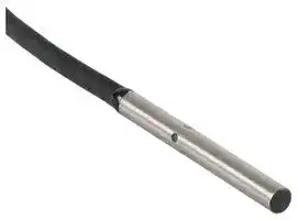


E2E-C03SR8-WC-B1 2M
Proximity Sensor, Inductive, 0.8 mm, PNP/SPST-NO, PVC Pre-Wired, 10 to 30 VDC
- Manufacturer: OMRON INDUSTRIAL AUTOMATION
- Product type: Inductive Proximity Sensors
- SVHC: To Be Advised
- Product Range: E2E Series
- Sensing Range Max: 0.8mm
- Sensor Output Type: PNP / SPST-NO
- Supply Voltage DC Max: 30V
- Supply Voltage DC Min: 10V
| Delivery and price | |
|---|---|
| Units per pack | 1 |
| Price | 69.77 € |
| Current stock | 10+ |
| Lead time | 30 days |
**Small-diameter Proximity Sensor E2E**

## **Ultra small size, but surprisingly easy installation!**

- With the addition of M4, 5.4-dia., 6.5-dia. size, unshielded, pre-wired connector model, and connector model, a total of 108 model variations are available.

- High-speed response frequency stably detects moving objects: 5 kHz max.

- Four indicator lamps for easier indicator positioning.

- Special mounting brackets reduce time and efforts for installation.

- Protective Stainless-steel Spiral Tube against wire breakage is available (M4, M5 only).

- Models also available with standard cables that are 5 m long or with robot (bending-resistant) cables.

For the most recent information on models that have been certified for safety standards, refer to your OMRON website.

Refer to _Safety Precautions_ on page 10.

## **Features**

## **Lineup of global small-diameter types (3 dia., 4 dia., 5.4 dia., 6.5 dia., M4, M5)**

- A lineup of unshielded models for long distance sensing is also available. Stable long distance sensing performance enables worry-free use even when the work flow is unsteady.

## **Bright operation indicators make it easy to check operation status**

- Four indicator lamps in a 360 degree layout can be easily seen.

**Environment friendly, low current consumption only 2/3 that of previous models**

- All have a current consumption of 10 mA max.

## **Protective Stainless-steel Spiral Tube against wire breakage is available**

- Lineup of protective tubes for M4 and M5 sizes. Reduces wire breakage due to catching and shock.

**==> picture [327 x 105] intentionally omitted <==**

**----- Start of picture text -----**<br>
Q.<br>Hs<br>**----- End of picture text -----**<br>


- **High-speed response enables sharp detection timing** • 5 kHz response frequency max.

**Protection circuits prevent failures due to wiring mistakes.**

• Load short-circuit protection and output reverse polarity protection circuits are incorporated.

**1**

**E2E**

## **E2E (Small Diameter) Model Number Legend**

|E2E-|E2E-|A|B|C|D|-|E|-|F <br>|G|-|H||I||
|---|---|---|---|---|---|---|---|---|---|---|---|---|---|---|---|
|**No.**|**Classification**||||||||**Code**||||**Meaning**|||
|A|Case material and shape||||||||C||||Cylindrical|||
||||||||||S||||SUS, threaded|||
|B|Size||||||||03||||Outer diameter 3 mm|||
||||||||||04||||Outer diameter 4 mm|||
||||||||||05||||Threaded: Outer diameter 5 mm, Cylindrical: Outer diameter 5.4 mm|||
||||||||||06||||Outer diameter 6.5 mm|||
|C|Shielding||||||||S||||Shielded Models|||
||||||||||N||||Unshielded Models|||
|D|Sensingdistance||||||||Number||||R8: 0.8 mm, 01: 1 mm, 12: 1.2 mm, 02: 2 mm, 03: 3 mm, 04: 4 mm|||
|E|Connecting method||||||||WC||||PVC Pre-wired Model|||
||||||||||MC||||M8 Connector, 3-pin|||
||||||||||CJ||||M8 Pre-wired Connector, 3-pin|||
|F|Output specifications||||||||B||||DC 3-wire PNP open-collector output|||
||||||||||C||||DC 3-wire NPN open-collector output|||
|G|Operation mode||||||||1||||Normallyopen (NO)|||
||||||||||2||||Normallyclosed (NC)|||
|H|Cable specifications||||||||Blank||||Standard PVC cable|||
||||||||||R||||Robot (bending-resistant) PVC cable|||
|I|Cable length||||||||Blank||||Connector Models|||
||||||||||Number M||||Cable length (Unit: m)<br>(Applicable to Pre-wired Models 2M/5M and Pre-wired Connector Models 0.3M)|||


**Note:** The purpose of this model number legend is to provide understanding of the meaning of specifications from the model number. Models are not available for all combinations of code numbers.

**2**

**E2E**

## **Ordering Information**

## **Sensors**

**Shielded Models [Refer to** _**Dimensions**_ **on page 12.]**

|**Appear-**<br>**ance**|**Sensing**<br>**distance**|**Connecting**<br>**method**|**Cable**<br>**specifications**|**Operation**<br>**mode**|**Wire color /**<br>**pin arrangement**|**Model**|**Model**|
|---|---|---|---|---|---|---|---|
|||||||**NPN output**|**PNP output**|
|3 dia.|**0.8mm**|Pre-wired Models<br>(2 m)|PVC<br>(oil-resistant)|NO|Brown: +V<br>Black: Output<br>Blue: 0 V|**E2E-C03SR8-WC-C1 2M*1**|**E2E-C03SR8-WC-B1 2M*1**|
|||||NC||**E2E-C03SR8-WC-C2 2M*1**|**E2E-C03SR8-WC-B2 2M*1**|
|||M8 Pre-wired<br>Connector<br>Models (0.3 m)|PVC<br>(oil-resistant)|NO|1: +V,<br>3: 0 V,<br>4: Control output|**E2E-C03SR8-CJ-C1 0.3M**|**E2E-C03SR8-CJ-B1 0.3M**|
|||||NC||**E2E-C03SR8-CJ-C2 0.3M**|**E2E-C03SR8-CJ-B2 0.3M**|
|4 dia.|**1.2mm**|Pre-wired Models<br>(2 m)|PVC<br>(oil-resistant)|NO|Brown: +V<br>Black: Output<br>Blue: 0 V|**E2E-C04S12-WC-C1 2M*1 *2 *3**|**E2E-C04S12-WC-B1 2M*1 *2 *3**|
|||||NC||**E2E-C04S12-WC-C2 2M*1 *2 *3**|**E2E-C04S12-WC-B2 2M*1 *2 *3**|
|||M8 Pre-wired<br>Connector<br>Models (0.3 m)|PVC<br>(oil-resistant)|NO|1: +V,<br>3: 0 V,<br>4: Control output|**E2E-C04S12-CJ-C1 0.3M**|**E2E-C04S12-CJ-B1 0.3M**|
|||||NC||**E2E-C04S12-CJ-C2 0.3M**|**E2E-C04S12-CJ-B2 0.3M**|
|||M8 Connector<br>Models|---|NO||**E2E-C04S12-MC-C1**|**E2E-C04S12-MC-B1**|
|||||NC||**E2E-C04S12-MC-C2**|**E2E-C04S12-MC-B2**|
|5.4 dia.|**1mm**|Pre-wired Models<br>(2 m)|PVC<br>(oil-resistant)|NO|Brown: +V<br>Black: Output<br>Blue: 0 V|**E2E-C05S01-WC-C1 2M*1 *2 *3**|**E2E-C05S01-WC-B1 2M*1 *2 *3**|
|||||NC||**E2E-C05S01-WC-C2 2M*1 *2**|**E2E-C05S01-WC-B2 2M*1 *2**|
|6.5 dia.|**2mm**|Pre-wired Models<br>(2 m)|PVC<br>(oil-resistant)|NO|Brown: +V<br>Black: Output<br>Blue: 0 V|**E2E-C06S02-WC-C1 2M*1 *2 *3**|**E2E-C06S02-WC-B1 2M*1 *2 *3**|
|||||NC||**E2E-C06S02-WC-C2 2M*1 *2 *3**|**E2E-C06S02-WC-B2 2M*1 *2 *3**|
|||M8 Pre-wired<br>Connector<br>Models (0.3 m)|PVC<br>(oil-resistant)|NO|1: +V,<br>3: 0 V,<br>4: Control output|**E2E-C06S02-CJ-C1 0.3M**|**E2E-C06S02-CJ-B1 0.3M**|
|||||NC||**E2E-C06S02-CJ-C2 0.3M**|**E2E-C06S02-CJ-B2 0.3M**|
|||M8 Connector<br>Models|---|NO||**E2E-C06S02-MC-C1**|**E2E-C06S02-MC-B1**|
|||||NC||**E2E-C06S02-MC-C2**|**E2E-C06S02-MC-B2**|
|M4|**0.8mm**|Pre-wired Models<br>(2 m)|PVC<br>(oil-resistant)|NO|Brown: +V<br>Black: Output<br>Blue: 0 V|**E2E-S04SR8-WC-C1 2M*1**|**E2E-S04SR8-WC-B1 2M*1**|
|||||NC||**E2E-S04SR8-WC-C2 2M*1**|**E2E-S04SR8-WC-B2 2M*1**|
|||M8 Pre-wired<br>Connector<br>Models (0.3 m)|PVC<br>(oil-resistant)|NO|1: +V,<br>3: 0 V,<br>4: Control output|**E2E-S04SR8-CJ-C1 0.3M**|**E2E-S04SR8-CJ-B1 0.3M**|
|||||NC||**E2E-S04SR8-CJ-C2 0.3M**|**E2E-S04SR8-CJ-B2 0.3M**|
|M5|**1.2mm**|Pre-wired Models<br>(2 m)|PVC<br>(oil-resistant)|NO|Brown: +V<br>Black: Output<br>Blue: 0 V|**E2E-S05S12-WC-C1 2M*1 *2 *3**|**E2E-S05S12-WC-B1 2M*1 *2 *3**|
|||||NC||**E2E-S05S12-WC-C2 2M*1 *2 *3**|**E2E-S05S12-WC-B2 2M*1 *2 *3**|
|||M8 Pre-wired<br>Connector<br>Models (0.3 m)|PVC<br>(oil-resistant)|NO|1: +V,<br>3: 0 V,<br>4: Control output|**E2E-S05S12-CJ-C1 0.3M**|**E2E-S05S12-CJ-B1 0.3M**|
|||||NC||**E2E-S05S12-CJ-C2 0.3M**|**E2E-S05S12-CJ-B2 0.3M**|
|||M8 Connector<br>Models|---|NO||**E2E-S05S12-MC-C1**|**E2E-S05S12-MC-B1**|
|||||NC||**E2E-S05S12-MC-C2**|**E2E-S05S12-MC-B2**|


- *1. Models with 5-m cable length are also available with "5M" suffix. (Example: E2E-C04S12-WC-C1 5M)

- *2. Models with robot (bending-resistant) cable are also available with "-R" in the model number. (Example: E2E-C04S12-WC-C1-R 2M)

- *3. Models with 5-m robot (bending-resistant) cable are also available with "-R" and the "5M" suffix in the model number. (Example: E2E-C04S12WC-C1-R 5M)

**3**

**E2E**

**Unshielded Models [Refer to** _**Dimensions**_ **on page 13.]**

|**Appear-**<br>**ance**|**Sensing**<br>**distance**|**Connecting**<br>**method**|**Cable**<br>**specifications**|**Operation**<br>**mode**|**Wire color /**<br>**pin arrangement**|**Model**|**Model**|
|---|---|---|---|---|---|---|---|
|||||||**NPN output**|**PNP output**|
|3 dia.|**2mm**|Pre-wired Models<br>(2 m)|PVC<br>(oil-resistant)|NO|Brown: +V<br>Black: Output<br>Blue: 0 V|**E2E-C03N02-WC-C1 2M*1**|**E2E-C03N02-WC-B1 2M*1**|
|||||NC||**E2E-C03N02-WC-C2 2M*1**|**E2E-C03N02-WC-B2 2M*1**|
|||M8 Pre-wired<br>Connector<br>Models (0.3 m)|PVC<br>(oil-resistant)|NO|1: +V,<br>3: 0 V,<br>4: Control output|**E2E-C03N02-CJ-C1 0.3M**|**E2E-C03N02-CJ-B1 0.3M**|
|||||NC||**E2E-C03N02-CJ-C2 0.3M**|**E2E-C03N02-CJ-B2 0.3M**|
|4 dia.|**3mm**|Pre-wired Models<br>(2 m)|PVC<br>(oil-resistant)|NO|Brown: +V<br>Black: Output<br>Blue: 0 V|**E2E-C04N03-WC-C1 2M*1 *2**|**E2E-C04N03-WC-B1 2M*1 *2**|
|||||NC||**E2E-C04N03-WC-C2 2M*1 *2**|**E2E-C04N03-WC-B2 2M*1 *2**|
|||M8 Pre-wired<br>Connector<br>Models (0.3 m)|PVC<br>(oil-resistant)|NO|1: +V,<br>3: 0 V,<br>4: Control output|**E2E-C04N03-CJ-C1 0.3M**|**E2E-C04N03-CJ-B1 0.3M**|
|||||NC||**E2E-C04N03-CJ-C2 0.3M**|**E2E-C04N03-CJ-B2 0.3M**|
|||M8 Connector<br>Models|---|NO||**E2E-C04N03-MC-C1**|**E2E-C04N03-MC-B1**|
|||||NC||**E2E-C04N03-MC-C2**|**E2E-C04N03-MC-B2**|
|6.5 dia.|**4mm**|Pre-wired Models<br>(2 m)|PVC<br>(oil-resistant)|NO|Brown: +V<br>Black: Output<br>Blue: 0 V|**E2E-C06N04-WC-C1 2M*1 *2**|**E2E-C06N04-WC-B1 2M*1 *2**|
|||||NC||**E2E-C06N04-WC-C2 2M*1 *2**|**E2E-C06N04-WC-B2 2M*1 *2**|
|||M8 Pre-wired<br>Connector<br>Models (0.3 m)|PVC<br>(oil-resistant)|NO|1: +V,<br>3: 0 V,<br>4: Control output|**E2E-C06N04-CJ-C1 0.3M**|**E2E-C06N04-CJ-B1 0.3M**|
|||||NC||**E2E-C06N04-CJ-C2 0.3M**|**E2E-C06N04-CJ-B2 0.3M**|
|||M8 Connector<br>Models|---|NO||**E2E-C06N04-MC-C1**|**E2E-C06N04-MC-B1**|
|||||NC||**E2E-C06N04-MC-C2**|**E2E-C06N04-MC-B2**|
|M4|**2mm**|Pre-wired Models<br>(2 m)|PVC<br>(oil-resistant)|NO|Brown: +V<br>Black: Output<br>Blue: 0 V|**E2E-S04N02-WC-C1 2M*1**|**E2E-S04N02-WC-B1 2M*1**|
|||||NC||**E2E-S04N02-WC-C2 2M*1**|**E2E-S04N02-WC-B2 2M*1**|
|||M8 Pre-wired<br>Connector<br>Models (0.3 m)|PVC<br>(oil-resistant)|NO|1: +V,<br>3: 0 V,<br>4: Control output|**E2E-S04N02-CJ-C1 0.3M**|**E2E-S04N02-CJ-B1 0.3M**|
|||||NC||**E2E-S04N02-CJ-C2 0.3M**|**E2E-S04N02-CJ-B2 0.3M**|
|M5|**3mm**|Pre-wired Models<br>(2 m)|PVC<br>(oil-resistant)|NO|Brown: +V<br>Black: Output<br>Blue: 0 V|**E2E-S05N03-WC-C1 2M*1 *2**|**E2E-S05N03-WC-B1 2M*1 *2**|
|||||NC||**E2E-S05N03-WC-C2 2M*1 *2**|**E2E-S05N03-WC-B2 2M*1 *2**|
|||M8 Pre-wired<br>Connector<br>Models (0.3 m)|PVC<br>(oil-resistant)|NO|1: +V,<br>3: 0 V,<br>4: Control output|**E2E-S05N03-CJ-C1 0.3M**|**E2E-S05N03-CJ-B1 0.3M**|
|||||NC||**E2E-S05N03-CJ-C2 0.3M**|**E2E-S05N03-CJ-B2 0.3M**|
|||M8 Connector<br>Models|---|NO||**E2E-S05N03-MC-C1**|**E2E-S05N03-MC-B1**|
|||||NC||**E2E-S05N03-MC-C2**|**E2E-S05N03-MC-B2**|


- *1. Models with 5-m cable length are also available with "5M" suffix. (Example: E2E-C04N03-WC-C1 5M)

- *2. Models with robot (bending-resistant) cable are also available with "-R" in the model number. (Example: E2E-C04N03-WC-C1-R 2M)

**4**

**E2E**

## **Accessories (Sold separately)**

## **Sensor I/O Connector (Socket on One Cable End)**

**A Sensor I/O Connector is not provided with the Sensor. It must be ordered separately as required. [Refer to** _**Dimensions**_ **on page 16.]**

|**Cable**<br>**specifications**|**Number of cable**<br>**wires (conductors)**|**Cable length L (m)**|**Straight**|
|---|---|---|---|
|Robot (bending-<br>resistant) cable|3|2|**XS3F-M321-302-R**|
|||5|**XS3F-M321-305-R**|


## **Mounting Brackets**

**A Mounting Bracket is not provided with the Sensor. It must be ordered separately as required. [Refer to** _**Dimensions**_ **on page 15.]**

|**Applicable**<br>**Sensors**<br>~~—~~|**Appearance**<br>~~—|~~|**Model**<br><br>~~|~~|**Quantity**<br><br>~~|~~|**Remarks**|
|---|---|---|---|---|
|E2E-C03@<br>~~—~~|~~— |S|~~|**Y92E-SC03**<br>~~S|~~<br>~~|~~|1<br>~~S|~~<br>~~|~~|Mounting block for 3 dia., M3-20 Hexagon socket head cap screws:<br>2pieces, M3×P0.5 Hexagon nuts: 2pieces, Washers: 2pieces|
|E2E-C04@<br>|~~S|~~<br>~~S|~~|**Y92E-SC04**<br>~~S|~~<br>~~|~~<br>~~S|~~|1<br>~~S|~~<br>~~|~~<br>~~S|~~|Mounting block for 4 dia., M3-20 Hexagon socket head cap screws:<br>2pieces, M3×P0.5 Hexagon nuts: 2pieces, Washers: 2pieces|
|E2E-C05@|~~S|~~<br>~~S|~~|**Y92E-SC05**<br>~~S|~~<br>~~S|~~|1<br>~~S|~~<br>~~S|~~|Mounting block for 5.4 dia., M3-20 Hexagon socket head cap screws:<br>2 pieces, M3×P0.5 Hexagon nuts: 2 pieces, Washers: 2 pieces|
|E2E-C06@|~~SBS~~|**Y92E-SC06**<br>~~SBS~~<br>~~|~~|1<br>~~SBS~~<br>~~|~~|Mounting block for 6.5 dia., M3-20 Hexagon socket head cap screws:<br>2pieces, M3×P0.5 Hexagon nuts: 2pieces, Washers: 2pieces|
|E2E-S04@|~~B’.~~<br>|**Y92E-SS04**<br>~~B’.~~<br>~~|~~<br>~~|~~|1<br>~~B’.~~<br>~~|~~<br>~~|~~|L-shaped Mounting Bracket for M4 screws<br>~~|~~|
|E2E-S05@|~~B’.~~<br>~~B®~~|**Y92E-SS05**<br>~~B’.~~<br>~~|~~<br>~~B®|~~|1<br>~~B’.~~<br>~~|~~<br>~~B®|~~|L-shaped Mounting Bracket for M5 screws<br>~~|~~|


## **Nut Set**

A Nut Set is included with the Sensor. Order a Nut Set when required, e.g., if you lose the nuts.

## **Protective Stainless-steel Spiral Tube against Wire Breakage**

**A Spiral Tube is not provided with the Sensor. It must be ordered separately as required.**

**[Refer to** _**Dimensions**_ **on page 16.]**

|**Applicable Sensors**|**Model**|**Applicable sensor outer**<br>**diameter**|**Length**|
|---|---|---|---|
|E2E-S04@|**Y92E-STS04-05**<br>~~—~~<br>~~Pp~~|M4<br>~~—~~<br>|0.5 m|
||**Y92E-STS04-10**<br>~~—~~<br>~~Pp~~||1 m|
|E2E-S05@|**Y92E-STS05-05**<br>~~—~~<br>~~Pp——~~|M5<br>~~—~~<br>~~——~~|0.5 m|
||**Y92E-STS05-10**<br>~~——~~||1 m|


**5**

**E2E**

## **Ratings and Specifications**

|**Size**|**Size**|**3 dia.**|**3 dia.**|**4 dia.**|**4 dia.**|**5.4 dia.**|**6.5 dia.**|**6.5 dia.**|**M4**|**M4**|**M5**|**M5**|
|---|---|---|---|---|---|---|---|---|---|---|---|---|
|**Type**||**Shielded**|**Unshielded**|**Shielded**|**Unshielded**|**Shielded**|**Shielded**|**Unshielded**|**Shielded**|**Unshielded**|**Shielded**|**Unshielded**|
|**Item**<br>**Model**||**E2E-**<br>**C03SR8@**|**E2E-**<br>**C03N02@**|**E2E-**<br>**C04S12@**|**E2E-**<br>**C04N03@**|**E2E-**<br>**C05S01@**|**E2E-**<br>**C06S02@**|**E2E-**<br>**C06N04@**|**E2E-**<br>**S04SR8@**|**E2E-**<br>**S04N02@**|**E2E-**<br>**S05S12@**|**E2E-**<br>**S05N03@**|
|**Sensing distance**<br>**(at 23**°**C)**||0.8 mm<br>±10%|2 mm<br>±10%|1.2 mm<br>±10%|3 mm<br>±10%|1mm<br>±10%|2 mm<br>±10%|4 mm<br>±10%|0.8 mm<br>±10%|2 mm<br>±10%|1.2 mm<br>±10%|3 mm<br>±10%|
|**Setting distance*1**<br>**(Sensing distance × 0.7)**||0 to 0.56<br>mm|0 to 1.4<br>mm|0 to 0.84<br>mm|0 to 2.1<br>mm|0 to 0.7<br>mm|0 to 1.4<br>mm|0 to 2.8<br>mm|0 to 0.56<br>mm|0 to 1.4<br>mm|0 to 0.84<br>mm|0 to 2.1<br>mm|
|**Differential travel**||15% max. of sensingdistance|||||||||||
|**Detectable object**||Ferrous metal(The sensingdistance decreases with non-ferrous metal. Refer to_Engineering Data_onpage 7.)|||||||||||
|**Standard sensing**<br>**object**||Iron, 3 × 3<br>× 1 mm|Iron, 6 × 6<br>× 1 mm|Iron, 4 × 4<br>× 1 mm|Iron, 9 × 9<br>× 1 mm|Iron, 5.4 × 5.4<br>× 1 mm|Iron, 6.5×6.5<br>×1 mm|Iron, 12×12<br>×1 mm|Iron, 3 × 3<br>× 1 mm|Iron, 6 × 6<br>× 1 mm|Iron, 4 × 4<br>× 1 mm|Iron, 9 × 9<br>× 1 mm|
|**Response frequency *2**||5 kHz|3.5 kHz|4 kHz|2 kHz|4 kHz|3 kHz|3 kHz|5 kHz|3.5 kHz|4 kHz|2 kHz|
|**Power supply voltage*3**||10 to 30 VDC(including10% ripple(p-p))|||||||||||
|**Current consumption**||10 mA max.|||||||||||
|**Control**<br>**output**<br>***4**|**Load current**|50 mA max.||100 mA max.|||200 mA max.<br>(60 to 70°C: 100 mA)||50 mA max.||100 mA max.||
||**Residual**<br>**voltage**|2 V max.*5|||||||||||
|**Indicators**||Operation indicator: Yellow(complies with European standard EN60947-5-2)Lights duringoutput.|||||||||||
|**Operation mode**||B1/B2: PNP open collector, C1/C2: NPN open collector<br>B1/C1 models: NO, B2/C2 models: NC|||||||||||
|**Protection circuits**||Output reversepolarity protection, Power source circuit reversepolarity protection, Surge suppressor, Load short-circuitprotection|||||||||||
|**Ambient**<br>**temperature range**||Operation and storage:−25 to 70°C (with no icing or condensation)|||||||||||
|**Ambient**<br>**humidity range**||Operation and storage: 35% to 95% (with no condensation)|||||||||||
|**Temperature**<br>**influence**||±15% max. of sensing distance at 23°C within temperature range of−25 to 70°C|||||||||||
|**Voltage influence**||±2.5% max. of sensingdistance at rated voltage in the rated voltage±15% range|||||||||||
|**Insulation resistance**||50 MΩmin.(at 500 VDC)between current-carrying parts and case|||||||||||
|**Dielectric strength**||500 VAC, 50/60 Hz for 1 minute between current-carrying parts and case|||||||||||
|**Vibration resistance**||Destruction: 10 to 55 Hz, 1.5-mm double amplitude for 2 hours each in X, Y, and Z directions|||||||||||
|**Shock resistance**||Destruction: 500 m/s210 times each in X, Y, and Z directions|||||||||||
|**Degree**|**ofprotection**|IEC 60529 IP67, in-house standards: oil-resistant*****6|||||||||||
|**Con-**<br>**necting**<br>**method**|**Pre-wired**<br>**Models**|Yes||Yes||Yes|Yes||Yes||Yes||
||**M8 Pre-wired**<br>**Connector**<br>**Models**|Yes||Yes||No|Yes||Yes||Yes||
||**M8 Connector**<br>**Models**|No||Yes||No|Yes||No||Yes||
|**Weight**<br>**(packed**<br>**state)**|**Pre-wired**<br>**Models**|Approx.<br>25g|Approx.<br>30g|Approx.<br>35g|Approx.<br>35g|Approx.<br>35g|Approx.<br>55g|Approx.<br>55g|Approx.<br>30g|Approx.<br>30g|Approx.<br>35g|Approx.<br>40g|
||**M8 Pre-wired**<br>**Connector**<br>**Models**|Approx.<br>20 g|Approx.<br>20 g|Approx.<br>15 g|Approx.<br>20 g|---|Approx.<br>20 g|Approx.<br>25 g|Approx.<br>20 g|Approx.<br>20 g|Approx.<br>20 g|Approx.<br>20 g|
||**M8 Connector**<br>**Models**|---|---|Approx.<br>10g|Approx.<br>10g|---|Approx.<br>10g|Approx.<br>15g|---|---|Approx.<br>15g|Approx.<br>15g|
|**Materi-**<br>**als**|**Case**|SUS303 (EN 1.4305)*7||||Nickel-<br>plated<br>brass|SUS303 (EN 1.4305)*7||||||
||**Sensing**<br>**surface**|Heat-resistant ABS|||||||||||
||**Clamping**<br>**nuts*8**|No|||||||SUS430 (EN 1.4016)*****7||||
||**Toothed**<br>**washer*8**|No|||||||SUS303 (EN 1.4305)*****7||||
||**Cable**|Polyvinyl chloride(PVC)|||||||||||
|**Acces-**<br>**sories**|**Instruction**<br>**manual**|Yes|||||||||||
||**Model label**|Yes|||||||||||
||**Mounting**<br>**brackets**|Sold separately|||||||||||


- *1. Using within the set distance enables high-speed responsiveness and a more stable repeat accuracy.

- *2. The response frequency is an average value.

- *3. When used at a power of 12 V, the Sensor is less susceptible to the effects of internal self heat generation and therefore a more stable repeat accuracy can be obtained.

- *4. When the control output is 20 mA or less, the Sensor is less susceptible to the effects of internal self heat generation and therefore a more stable repeat accuracy can be obtained.

- *5. 3 dia., M4: load current 50 mA, cable length 2 m

   - 4 dia., 5.4 dia., M5: load current 100 mA, cable length 2 m

   - 6.5 dia.: load current 200 mA, cord length 2 m

- *6. Oil resistance in-house standard: Performance with respect to water insoluble oil. (Test at right)

- *7. Material name in EN standards.

- *8. Clamping nuts: 2 pieces, toothed washer: 1 piece

Oil resistance test

After the test time elapses, the characteristics below are checked for problems.

- (1) Visual appearance (no damage that affects product characteristics)

- (2) Operation check (ON/OFF)

- (3) Insulation resistance (50 MΩ min. at 500 VDC)

- (4) Dielectric strength (500 VAC, 1 min.)

- (5) Water resistance (IP67)

**==> picture [60 x 72] intentionally omitted <==**

Test oil: Water insoluble oil Velocite No. 3 (manufactured by Exxon Mobil) 50°C × 250 hours Depth 10 cm

Sensor

**6**

**E2E**

**Engineering Data (Reference Value)**

## **Sensing Area**

## **Shielded Models E2E-C/S** @ **S** @

## **Unshielded Models**

## **E2E-C/S** @ **N** @

**==> picture [511 x 689] intentionally omitted <==**

**----- Start of picture text -----**<br>
2.5 4.5<br>E2E-C06N04@<br>E2E-C06S02@ 4<br>2 3.5<br>3<br>E2E-C04S12@<br>1.5 E2E-S05S12@<br>2.5 E2E-C04N03@<br>E2E-S05N03@<br>2<br>1<br>E2E-C05S01@ 1.5 E2E-C03N02@<br>E2E-S04N02@<br>E2E-C03SR8@ 1<br>0.5 E2E-S04SR8@<br>0.5 Note:  The workpiece is a standard sensing<br>object.<br>0-8  -6  -4  -2  0  2  4  6  8 0-10 -5 0 5 10 For details, refer to  Ratings and<br>Distance Y (mm) Distance Y (mm) Specifications  on page 6.<br>Influence of Sensing Object Size and Material<br>Shielded Models<br>E2E-C03SR8 @/ E2E-S04SR8 @ E2E-C04S12 @/ E2E-S05S12 @ E2E-C05S01 @<br>0.9 1.6 1.6<br>@d<br>0.8 Iron 1.4 1.4 X t = 1 mm<br>0.7<br>1.2 Iron 1.2<br>0.6 @d t = 1 mm<br>Stainless steel  1.0 X 1.0 Iron<br>0.5 (SUS304)Brass Stainless steel (SUS304)<br>0.4 Aluminum 0.8 Stainless steel (SUS304) 0.8 Brass<br>0.3 Copper 0.6 0.6 Aluminum<br>0.2 @d X t = 1 mm 0.4 Brass 0.4 Copper<br>Aluminum<br>0.1 0.2 0.2<br>Copper<br>0 5 10 15 20 25 30 35 0 5 10 15 20 25 30 35 0  5  10  15  20  25  30  35<br>Side length of sensing object: d (mm) Side length of sensing object: d (mm) Side length of sensing object: d (mm)<br>E2E-C06S02 @<br>2.5<br>2 Iron<br>@d<br>t = 1 mm<br>X<br>1.5<br>1 Stainless steel<br>(SUS304)<br>0.5 Brass<br>Aluminum<br>Copper<br>0 5 10 15 20 25 30 35<br>Side length of sensing object: d (mm)<br>Unshielded Models<br>E2E-C03N02@/E2E-S04N02@ E2E-C04N03 @ /E2E-S05N03 @ E2E-C06N04 @<br>2.5 3.5 5<br>@d<br>t = 1 mm<br>3 Iron X<br>2 Iron 4 Iron<br>2.5 Stainless steel<br>Stainless steel  (SUS304)<br>(SUS304)<br>1.5 3<br>2 Stainless steel<br>Brass (SUS304)<br>Brass<br>1 Aluminum 1.5 Aluminum 2<br>Copper<br>@d Copper 1 @d Brass<br>t = 1 mm t = 1 mm Aluminum<br>0.5 X X 1<br>0.5 Copper<br>0 5 10 15 20 25 30 35 0 5 10 15 20 25 30 35 0 5 10 15 20 25 30 35<br>Side length of sensing object: d (mm) Side length of sensing object: d (mm) Side length of sensing object: d (mm)<br>Distance X (mm) Distance X (mm)<br>Distance X (mm) Distance X (mm) Distance X (mm)<br>Distance X (mm)<br>Distance X (mm) Distance X (mm) Distance X (mm)<br>Y Y<br>X X<br>**----- End of picture text -----**<br>


**7**

**E2E**

## **Distance - Horizontal Repeat Accuracy**

## **Shielded Models**

## E2E-C03SR8@/E2E-S04SR8@

**==> picture [500 x 329] intentionally omitted <==**

**----- Start of picture text -----**<br>
E2E-C03SR8@/E2E-S04SR8@ E2E-C04S12@/E2E-S05S12@ E2E-C05S01@<br>0.8 1.2 1.2<br>12 VDC 12 VDC<br>0.7 24 VDC<br>24 VDC 1 1<br>12 VDC<br>0.6 24 VDC<br>0.8 0.8<br>0.5<br>0.4 0.6 0.6<br>@3 × 1 mm @4 × 1 mm @5.4 × 1 mm<br>0.3 X ON point repeat accuracy 0.4 X ON point repeat accuracy 0.4 X ON point repeat accuracy<br>0.2<br>0.2 0.2<br>0.1<br>0  0.05  0.1  0.15  0.2 0  0.05  0.1  0.15  0.2 0  0.05  0.1  0.15  0.2<br>Repeat accuracy (mm) Repeat accuracy (mm) Repeat accuracy (mm)<br>E2E-C06S02@<br>2<br>1.8 12 VDC 24 VDC<br>1.6<br>1.4<br>1.2<br>1<br>0.8 @6.5 × 1 mm ON point<br>X repeat<br>0.6 accuracy<br>0.4<br>0.2<br>0  0.05  0.1  0.15  0.2<br>Repeat accuracy (mm)<br>Distance X (mm) Distance X (mm) Distance X (mm)<br>Distance X (mm)<br>**----- End of picture text -----**<br>


## **Unshielded Models**

## E2E-C03N02@/E2E-S04N02@

## E2E-C04N03@/E2E-S05N03@ E2E-C06N04@

**==> picture [500 x 147] intentionally omitted <==**

**----- Start of picture text -----**<br>
2 3 4<br>1.8 12 VDC 24 VDC 12 VDC 24 VDC 3.5 12 VDC 24 VDC<br>2.5<br>1.6<br>3<br>1.4<br>2<br>2.5<br>1.2<br>1 1.5 2<br>0.80.6 @6 × 1 mmX ON point repeat accuracy 1 @9 × 1 mmX ON point repeat accuracy 1.5 @12 × 1 mmX ON point repeat accuracy<br>1<br>0.4<br>0.5<br>0.5<br>0.2<br>0  0.1  0.2  0.3  0.4  0.5 0  0.1  0.2  0.3  0.4  0.5 0  0.1  0.2  0.3  0.4  0.5<br>Repeat accuracy (mm) Repeat accuracy (mm) Repeat accuracy (mm)<br>Distance X (mm) Distance X (mm) Distance X (mm)<br>**----- End of picture text -----**<br>


## **Sensing distance vs. repeat accuracy graphs**

By using within the sensor installation distance, the repeat accuracy stabilizes. This data is reference data based on a standard sensing object, and is not a guarantee of performance. The repeat accuracy varies depending on the effects of temperature, the material and surface condition of the sensing object, and other conditions.

## **Minimum measurement gap**

|**Model**|**Minimum gap (mm)**|
|---|---|
|E2E-C03S/S04S|0.3|
|E2E-C03N/S04N|0.6|
|E2E-C04S/S05S|0.4|
|E2E-C04N/S05N|0.9|
|E2E-C05S|0.3|
|E2E-C06S|0.6|
|E2E-C06N|1.2|


**Note:** Measured at constant temperature of 23ºC using an iron sensing object of size at least as large as standard sensing object (see right).

## **Size of test piece**

**==> picture [139 x 95] intentionally omitted <==**

**----- Start of picture text -----**<br>
gap<br>30 mm<br>15 mm<br>30 mm Material: Iron<br>**----- End of picture text -----**<br>


**8**

**E2E**

## **I/O Circuit Diagrams**

**==> picture [511 x 485] intentionally omitted <==**

**----- Start of picture text -----**<br>
Operationmode specificationsOutput Model Timing chart Output circuit<br>Non-sensing area Sensing area<br>Proximity<br>Sensor<br>Sensing<br>object<br>Brown [1]<br>(%) 100 0<br>E2E-@@@@<br>NO -@@-C1 Ratedsensing Load<br>distance Proximity<br>Sensor Black 4<br>ON Operation main 10 to 30 VDC<br>OFF indicator (yellow) circuit<br>ON Control<br>NPN open- OFF output Blue 3<br>collector<br>output Non-sensing area Sensing area Proximity<br>Sensor<br>Sensing<br>object Connector pin arrangement<br>(%) 100 0 4<br>E2E-@@@@ 1 3<br>NC -@@-C2 Ratedsensing<br>distance<br>ON Operation M8<br>indicator<br>OFF (yellow)<br>ON Control<br>OFF output<br>Non-sensing area Sensing area<br>Proximity<br>Sensor<br>Sensing<br>object<br>Brown [1]<br>(%) 100 0<br>E2E-@@@@<br>NO -@@-B1 Ratedsensing<br>distance Proximity<br>Sensor Black [4]<br>ON Operation main 10 to 30 VDC<br>indicator  circuit<br>OFF (yellow) Load<br>ON Control<br>PNP open- OFF output Blue [3]<br>collector<br>output Non-sensing area Sensing area Proximity<br>Sensor<br>Sensing<br>object Connector pin arrangement<br>(%) 100 0 4<br>E2E-@@@@ 1 3<br>NC -@@-B2 Ratedsensing<br>distance<br>ON Operation M8<br>indicator<br>OFF (yellow)<br>ON Control<br>OFF output<br>**----- End of picture text -----**<br>


## **Connection to I/O Connector (Connector Models, Pre-wired Connector Models)**

## **Sensor I/O Connector**

**==> picture [470 x 97] intentionally omitted <==**

**----- Start of picture text -----**<br>
1 1 Brown<br>NPN 4 4 Black<br>3 3 Blue 02: 2 m05: 5 m connector arrangement diagramI/O connector cable,<br>XS3F-M32 @ -3 @@ -R<br>4<br>1: Straight 3 1<br>1 1 Brown 2: Right-angle<br>PNP 4 4 Black<br>3 3 Blue<br>**----- End of picture text -----**<br>


**9**

**E2E**

## **Safety Precautions**

## **Refer to** _**Warranty and Limitations of Liability**_ **.**

## **WARNING**

**This product is not designed or rated for ensuring safety of persons either directly or indirectly. Do not use it for such purposes.**

## **CAUTION**

- **Do not short the load. Explosion or burning may result.**

- **Do not supply power to the Sensor with no load, otherwise Sensor may be damaged.**

## **Precautions for Correct Use**

Do not use this product under ambient conditions that exceed the ratings.

## ● **Design**

## **Influence of Surrounding Metal**

When mounting the Sensor within a metal panel, ensure that the clearances given in the following table are maintained. Failure to maintain these distances may cause deterioration in the performance of the Sensor.

## 〈 **Shielded Models** 〉

## 〈 **Unshielded Models** 〉

**==> picture [511 x 40] intentionally omitted <==**

**----- Start of picture text -----**<br>
L L<br>D d dia. mn C D d dia. mn<br>**----- End of picture text -----**<br>


|**Size**|**3 dia.**|**4 dia.**|**5.4 dia.**<br>**6**|**.5 dia.**|**M4**|**M5**<br>0<br>5<br>5<br>0<br>10<br>0|**Size**|**3 dia.**|**4 dia.**|**6.5 dia.**|**M4**|**M5**|
|---|---|---|---|---|---|---|---|---|---|---|---|---|
|**Item**|||||||**Item**||||||
|**L**|0|0|0|0|0||**L**|6|6|12|6|6|
|**m**|3|5|3|6|3||**m**|6|9|8|6|9|
|**d**|3|4|5.4|6.5|4||**d**|9|12|24|9|12|
|**D**|0|0|0|0|0||**D**|6|6|12|6|6|
|**n**|8|10|8|12|8||**n**|16|20|24|16|20|
|**c**|0|0|0|2|0||||||||


If mounted in a surrounding non-magnetic metal such as aluminum or copper, the sensing distance may shorten by about 40 to 50%. If used in a recessed installation, take into consideration the effects of the material on the sensing distance.

## **Mutual Interference**

When installing Sensors face-to-face or side-by-side, ensure that the minimum distances given in the following table are maintained.

**==> picture [165 x 52] intentionally omitted <==**

**----- Start of picture text -----**<br>
B<br>A<br>A<br>**----- End of picture text -----**<br>


## **Mutual Interference**

(Unit: mm)

|**Size**|**3 dia.**|**3 dia.**|**4 dia.**|**4 dia.**|**5.4 dia.**|**6.5 dia.**|**6.5 dia.**|**M4**|**M4**|**M5**|**M5**|
|---|---|---|---|---|---|---|---|---|---|---|---|
|**Item**|**Shielded**|**Unshielded**|**Shielded**<br>|**Unshielded**|**Shielded**|**Shielded**|**Unshielded**<br>|**Shielded**|**Unshielded**|**Shielded**|**Unshielded**|
|**A**|20|80|20|80|20|20|80|20|80|20|80|
|**B***|15|60|15|60|15|15|60|15|60|15|60|


* Values when the connector size is not taken into consideration.

**10**

**E2E**

## ● **Mounting**

## **Tightening Force**

## 〈 **Mounting threaded models (E2E-S** @ **)** 〉

Do not tighten the nut with excessive force. A washer must be used with the nut.

## Tr

## ● **High-speed responsiveness**

To obtain a better high-speed response, it is recommended that you use the sensor at about 50% of the possible sensing distance. A high-speed response may not be obtained with some sensing object surfaces, materials, and shapes, or when the sensing distance is greater than the set distance. For the effects of materials, refer to _Engineering Data_ on page 7.

## ● **Protective Stainless-steel Spiral Tube**

The spiral tube is in a fixed state and is intended to provide protection against wire breakage due to shock from tools or other objects.

|**Note: 1.**<br>Only use the provided nut and toothed washer.<br>Risk of changes in the sensing distance and damage if a different<br>material is used. If you lose the nut or washer, purchase an optional nut<br>set.<br>**2.** The following strengths assume washers are being used.|**Note: 1.**<br>Only use the provided nut and toothed washer.<br>Risk of changes in the sensing distance and damage if a different<br>material is used. If you lose the nut or washer, purchase an optional nut<br>set.<br>**2.** The following strengths assume washers are being used.|**Note: 1.**<br>Only use the provided nut and toothed washer.<br>Risk of changes in the sensing distance and damage if a different<br>material is used. If you lose the nut or washer, purchase an optional nut<br>set.<br>**2.** The following strengths assume washers are being used.|**Note: 1.**<br>Only use the provided nut and toothed washer.<br>Risk of changes in the sensing distance and damage if a different<br>material is used. If you lose the nut or washer, purchase an optional nut<br>set.<br>**2.** The following strengths assume washers are being used.|**Note: 1.**<br>Only use the provided nut and toothed washer.<br>Risk of changes in the sensing distance and damage if a different<br>material is used. If you lose the nut or washer, purchase an optional nut<br>set.<br>**2.** The following strengths assume washers are being used.|
|---|---|---|---|---|
|**Size**|**M4**||**M5**||
|**Item**|**Shielded**|**Unshielded**|**Shielded**|**Unshielded**|
|**Tr**|0.8 N·m||1 N·m||


**Note:** Only use the provided nut.

## 〈 **Mounting unthreaded cylindrical models (E2E-C** @ **)** 〉

~~L~~ Dimpled end of set screw (M3) (Screw not provided)

**==> picture [74 x 51] intentionally omitted <==**

|**Size**<br>**Item**|**3**<br>**Shielded**|**dia.**<br>**Unshielded**|**4**<br>**Shielded**|**dia.**<br>**Unshielded**|**dia.**<br>**Unshielded**|**5.4**<br>**dia.**<br>**Shielded**||**6.5**<br>**Shielded**|**6.5**<br>**Shielded**|**dia.**<br>**Unshielded**|
|---|---|---|---|---|---|---|---|---|---|---|
|**L***|9 to 21<br>mm|15 to 27<br>mm|8 to 21<br>mm||14 to 27<br>mm|8 to 21<br>mm||12 to||26 mm|
|**Torque**||0.2 N·m max.||||0.4||N·m max.|||


* Excluding the operation indicator area.

When using a set screw, tighten it to the torque indicated in the table above. Using a set screw in any area other than specified by the above dimensions may result in fire or other occurrences due to damage to the internal circuit.

## ● **Oil resistance**

## ● **Repeated cable bending tolerance**

If you require repeated bending tolerance, use a sensor with a robot (bending-resistant) cable or use a Connector Model together with a connector cable that is specified for bending tolerance. (Example: XS3F-M321- @@@ -R) Refer to _Sensor I/O Connector_ on page 5.

## ● **Block type mounting accessories**

Due to differences in dimensional tolerances, these cannot be used with older small diameter proximity sensors. (E2E-CR6 @ , E2ECR8 @ , E2E-C1 @ )

## ● **Bending radius for mounting**

If the cable is bent from its base, the resin on the surface of the cable may peel off, however, this will not affect the protective structure or sensing performance.

Avoid bending the cable at less than 10 mm from the base. When bending the cable, refer to the table below.

||**Cable diameter**<br>**Bending radius***|||10 mm||
|---|---|---|---|---|---|
||3 dia., M4<br>7 mm<br>4 dia., 5.4 dia., M5<br>9 mm||Sensor||R|
||6.5 dia.<br>12 mm|||||
|*|For a robot (bending-resistant) cable,<br>|||||


- For a robot (bending-resistant) cable, multiply the bending radius in the above table by 1.7.

## ● **Total Cable Length**

If you extend the cable length, use a conductor cross section of 0.14 mm[2] or greater and do not exceed a total length of 200 m for standard cables or robot (bending-resistant) cables. It is assumed that an independent metal conduit will be used.

In accordance with our oil resistance standard, we test oil resistance based on water insoluble oil (complies with test oil based on JIS C0920, Appendix 1).

When water soluble cutting oil is used, durability varies due to the dilution ratio and other factors. Please test oil resistance using the actual oil that will be used.

**11**

**E2E**

(Unit: mm)

Tolerance class IT16 applies to dimensions in this data sheet unless otherwise specified.

## **Dimensions**

## **Sensors**

**Pre-wired Models (Shielded)**

**==> picture [504 x 338] intentionally omitted <==**

**----- Start of picture text -----**<br>
Mounting Hole Dimensions<br>(Shielded)<br>Dimension 3 dia. 4 dia. 5.4 dia. 6.5 dia. M4 M5<br>F (mm) 3.3 +0.50 4.2 +0.50 5.7 +0.50 7 +0.50 4.5 +0.50 5.5 +0.50<br>F<br>E2E-C03SR8-WC- @@ E2E-C04S12-WC- @@<br>3-0.1 [0] [ dia.] 27.1 2.4-dia. vinyl-insulated round cable with 3 conductors (Conductor cross section: 0.09 mm [2] ,  4-0.1 [0] [ dia.] 18.5 25.1<br>18 Insulator diameter: 0.7 mm), Standard length: 2 m<br>*<br>y by<br>Operation indicators (yellow) 4 × 90°<br>Operation indicators (yellow) 4 × 90° *  2.9-dia. vinyl-insulated round cable with 3 conductors (Conductor cross section:<br>0.14 mm [2] , Insulator diameter: 0.8 mm), Standard length: 2 m<br>   Model with robot (bending-resistant) cable: 2.9-dia. vinyl-insulated round cable<br>with 3 conductors (Conductor cross section: 0.15 mm [2] ,<br>   Insulator diameter: 1.05 mm), Standard length: 2 m<br>E2E-C05S01-WC- @@ E2E-C06S02-WC- @@<br>5.4-0.1 [0] [ dia.] 18.5 25.1 6.5-0.1 [0] [ dia.] 24.1 36<br>* *<br>@ @ Operation indicators (yellow) 4 × 90° B= he<br>*  2.9-dia. vinyl-insulated round cable with 3 conductors (Conductor cross section:  *  4-dia. vinyl-insulated round cable with 3 conductors (Conductor cross section:<br>0.14 mm [2] , Insulator diameter: 0.8 mm), Standard length: 2 m 0.14 mm [2] , Insulator diameter: 0.85 mm), Standard length: 2 m<br>   Model with robot (bending-resistant) cable: 2.9-dia. vinyl-insulated round cable     Model with robot (bending-resistant) cable: 4-dia. vinyl-insulated round cable<br>with 3 conductors (Conductor cross section: 0.15 mm [2] ,  with 3 conductors (Conductor cross section: 0.3 mm [2] ,<br>   Insulator diameter: 1.05 mm), Standard length: 2 m    Insulator diameter: 1.2 mm), Standard length: 2 m<br>E2E-S04SR8-WC- @@ E2E-S05S12-WC- @@<br>27.1 25.1 * 2.9-dia. vinyl-insulated round cable with 3<br>18 2.4-dia. vinyl-insulated round cable with 3 conductors  18.5 conductors (Conductor cross section: 0.14 mm [2] ,<br>8.5 dia. 15.1 5 Insulator diameter: 0.7 mm), Standard length: 2 m(Conductor cross section: 0.09 mm [2] ,   10 dia. 15.1 4 Insulator diameter: 0.8 mm), Standard length: 2 mModel with robot (bending-resistant) cable: 2.9-dia.<br>7 0.6 1 * Threaded section to secure  8 0.6 1 vinyl-insulated round cable with 3 conductors<br>3 * the Protective Stainless-steel  3 * (Conductor cross section: 0.15 mm [2] ,<br>| Geel Spiral Tube (optional).Mounting with clamping nuts  | E *Insulator diameter: 1.05 mm), Standard length: 2 m* Threaded section to secure<br>© M4  ×  P0.5 A / | Operation indicators (yellow) 4 × 90° Bie and a toothed washer is not possible here. Zz M5  ×  P0.5 | Operation indicators (yellow) 4 × 90° aos the Protective Stainless-steel Spiral Tube (optional).<br>Two clamping nuts Toothed washer Two clamping nuts Toothed washer Mounting with clamping nuts<br>and a toothed washer is not<br>possible here.<br>Operation indicators (yellow) 4 × 90°<br>**----- End of picture text -----**<br>


## **M8 Pre-wired Connector Models (0.3 m) (Shielded)**

**==> picture [509 x 277] intentionally omitted <==**

**----- Start of picture text -----**<br>
E2E-C03SR8-CJ- @@ E2E-C04S12-CJ- @@<br>2.4-dia. vinyl-insulated round cable,  2.9-dia. vinyl-insulated round cable,<br>3-0.1 [0] [ dia.] 18 27.1 Standard length: 300 mm 4-0.1 [0] [ dia.] 18.5 25.1 Standard length: 300 mm<br>=<br>: eCs J SkeTL<br>Operation indicators (yellow) 4 × 90° M8 × P1 Operation indicators (yellow) 4 × 90° M8 × P1<br>E2E-C06S02-CJ- @@ E2E-S04SR8-CJ- @@<br>27.1<br>18<br>36 4-dia. vinyl-insulated round cable,  8.5 dia. 15.1<br>6.5-0. [0] 1 [ dia.] 24.1 Standard length: 300 mm 7 0.6 3 15* 2.4-dia. vinyl-insulated round cable, Standard length: 300 mm M8 × P1<br>Operation indicators (yellow) 4 × 90° M8 × P1 M4  ×  P0.5<br>Operation indicators (yellow) 4 × 90°<br>Two clamping nuts Toothed washer * Mounting with clamping nuts and a toothed<br>washer is not possible on this threaded section.<br>E2E-S05S12-CJ- @@<br>25.1<br>18.5<br>10 dia. 15.1<br>8 0.6 3 4* 1 2.9-dia. vinyl-insulated round cable, Standard length: 300 mm M8 × P1<br>oeea<br>M5  ×  P0.5 / Operation indicators (yellow) 4 × 90° =|<br>Two clamping nuts Toothed washer * Mounting with clamping nuts and a toothed<br>washer is not possible on this threaded section.<br>**----- End of picture text -----**<br>


**12**

**E2E**

## **M8 Connector Models (Shielded)**

## **E2E-C04S12-MC-** @@

**==> picture [427 x 191] intentionally omitted <==**

**----- Start of picture text -----**<br>
@@ E2E-C06S02-MC- @@<br>40.1 43.5<br>4-0.1 [0] [ dia.] 24.2 4 6.5-0.1 [0] [ dia.] 28.5<br>18.5 24.1 4<br>= = fl | ba<br>6.75 dia.<br>6.75 dia.<br>Operation indicators (yellow) 4 × 90° M8 × P1 Operation indicators (yellow) 4 × 90° M8 × P1<br>@@<br>40.1<br>24.2<br>18.5<br> 10 dia. 15.1<br>0.6 4<br>8<br>3<br>yey iarSSi; cone Seas || | __<br>M5  ×  P0.5 / 6.75 dia. M8 × P1<br>Two clamping nuts Operation indicators (yellow) 4 × 90°<br>Toothed washer<br>**----- End of picture text -----**<br>


## **E2E-S05S12-MC-** @@

## **Pre-wired Models (Unshielded)**

## **Mounting Hole Dimensions**

|**Dimension**|**3 dia.**|**4 dia.**|**6.5 dia.**|**M4**|**M5**|
|---|---|---|---|---|---|
|F (mm)|3.3<br>+0.5<br>0|4.2<br>+0.5<br>0|7<br>+0.5<br>0|4.5<br>+0.5<br>0|5.5<br>+0.5<br>0|


**==> picture [5 x 5] intentionally omitted <==**

**----- Start of picture text -----**<br>
F<br>**----- End of picture text -----**<br>


## **E2E-C04N03-WC-** @@

## **E2E-C03N02-WC-** @@

**==> picture [504 x 173] intentionally omitted <==**

**----- Start of picture text -----**<br>
33 2.4-dia. vinyl-insulated round cable with 3 conductors  31<br>3-0.1 [0] [ dia.] 6 23.9 (Conductor cross section: 0.09 mmInsulator diameter: 0.7 mm), Standard length: 2 m [2] ,  4-0.1 [0] [ dia.] 6 24.4<br>i | |<br>*<br>Operation indicators (yellow) 4 × 90°<br>Operation indicators (yellow) 4 × 90°<br>*  2.9-dia. vinyl-insulated round cable with 3 conductors (Conductor cross section:<br>0.14 mm [2] , Insulator diameter: 0.8 mm), Standard length: 2 m<br>   Model with robot (bending-resistant) cable: 2.9-dia. vinyl-insulated round cable<br>with 3 conductors (Conductor cross section: 0.15 mm [2] ,<br>   Insulator diameter: 1.05 mm), Standard length: 2 m<br>E2E-C06N04-WC- @@ E2E-S04N02-WC- @@<br>35.9 33 2.4-dia. vinyl-insulated round cable with 3 conductors<br>6.5-0.1-0.1 [[0]] [[ dia.]] 6 24.2  8.5 dia. 21 23.9 5 (Conductor cross section: 0.09 mmInsulator diameter: 0.7 mm), Standard length: 2 m [2] ,<br>* 7 3-0.10 dia. 6.65 3 1 * * Threaded section to secure the Protective Stainless-steel Spiral Tube (optional).<br>Operation indicators (yellow) 4 × 90° Mounting with clamping nuts<br>*  4-dia. vinyl-insulated round cable with 3 conductors (Conductor cross section: 4-dia. vinyl-insulated round cable with 3 conductors (Conductor cross section:  (©)©) a|a | palae-——} 4 — _s-s- and a toothed washer is not<br>0.14 mm [[2]] , Insulator diameter: 0.85 mm), Standard length: 2 m M4  ×  P0.5 Operation indicators (yellow) 4 × 90° possible here.<br>Two clamping nuts Toothed washer<br>**----- End of picture text -----**<br>


## **E2E-C06N04-WC-** @@

**==> picture [149 x 51] intentionally omitted <==**

**----- Start of picture text -----**<br>
35.9<br>6.5-0.1-0.1 [[0]] [[ dia.]] 6 24.2<br>*<br>Operation indicators (yellow) 4 × 90°<br>**----- End of picture text -----**<br>


- 4-dia. vinyl-insulated round cable with 3 conductors (Conductor cross section: 4-dia. vinyl-insulated round cable with 3 conductors (Conductor cross section: 0.14 mm[[2]] , Insulator diameter: 0.85 mm), Standard length: 2 m

- Model with robot (bending-resistant) cable: 4-dia. vinyl-insulated round cable with 3 conductors (Conductor cross section: 0.3 mm[2] ,

- Insulator diameter: 1.2 mm), Standard length: 2 m

## **E2E-S05N03-WC-** @@

~~**31**~~ 24.4 10 dia. 4 ~~21~~ 6.5 1 ~~8~~ 4-0.10 dia. 6 3 *2 ~~as~~ *1 **M5** × **P0.5** Operation indicators (yellow) 4 × 90° Two clamping nuts Toothed washer

- *1 2.9-dia. vinyl-insulated round cable with 3 conductors (Conductor cross section: 0.14 mm[2] , Insulator diameter: 0.8 mm), Standard length: 2 m Model with robot (bending-resistant) cable: 2.9-dia. vinyl-insulated round cable with 3 conductors (Conductor cross section: 0.15 mm[2] , Insulator diameter: 1.05 mm), Standard length: 2 m

- *2 Threaded section to secure the Protective Stainless-steel Spiral Tube (optional). Mounting with clamping nuts and a toothed washer is not possible here.

**13**

**E2E**

**M8 Pre-wired Connector Models (0.3 mm) (Unshielded)**

**==> picture [496 x 293] intentionally omitted <==**

**----- Start of picture text -----**<br>
E2E-C03N02-CJ- @@ E2E-C04N03-CJ- @@<br>33 2.4-dia. vinyl-insulated round cable, Standard length: 300 mm 31 2.9-dia. vinyl-insulated round cable, Standard length: 300 mm<br>23.9 24.4<br>3-0.1 [0] [ dia.] 6 4-0.1 [0] [ dia.] 6<br>Uo Ges=4een(7 | 6 eo<br>Operation indicators (yellow) 4 × 90° M8 × P1 Operation indicators (yellow) 4 × 90° M8 × P1<br>E2E-C06N04-CJ- @@ E2E-S04N02-CJ- @@<br>33<br>6.5-0.1 [0] [ dia.] 6 24.2 35.9 4-dia. vinyl-insulated round cable, Standard length: 300 mm  8.5 dia. 7 3-0.10 dia. 6.56 2123.9 3 15* 2.4-dia. vinyl-insulated round cable, Standard length: 300 mm M8 × P1<br>CO SSS ster | © Hope onc TEA<br>Operation indicators (yellow) 4 × 90° M8 × P1 M4  ×  P0.5 F Operation indicators (yellow) 4 × 90° 2<br>Two clamping nuts Toothed washer * Mounting with clamping nuts and a<br>toothed washer is not possible on<br>this threaded section.<br>E2E-S05N03-CJ- @@<br>31<br>10 dia. 24.4 4<br>6.5 21 1 2.9-dia. vinyl-insulated round cable,<br>8 4-0.10 dia. 6 3 * Standard length: 300 mm<br>o M5  ×  P0.5 a eee Operation indicators (yellow) 4 × 90° a) 20 M8 × P1<br>Two clamping nuts Toothed washer<br>* Mounting with clamping nuts and a<br>toothed washer is not possible on<br>this threaded section.<br>**----- End of picture text -----**<br>


## **M8 Connector Models (Unshielded)**

**E2E-C04N03-MC-** @@

**==> picture [426 x 189] intentionally omitted <==**

**----- Start of picture text -----**<br>
@@ E2E-C06N04-MC- @@<br>46 43.4<br>30.1 28.4<br>4  -0.10 dia.  6 24.4 4 6.5  -0.10 dia.  6 24.2 4<br>6 Tenn zal<br>c= se 6.75 dia. 5 St<br>6.75 dia.<br>Operation indicators (yellow) 4 × 90° M8 × P1 Operation indicators (yellow) 4 × 90° M8 × P1<br>@@<br>46<br>30.1<br>24.4<br>10 dia.<br>21<br>6.5 4<br>8 3<br>4 -0.10 dia. 6<br>c y ai l r<br>le M8 × P1<br>M5  ×  P0.5 / Operation indicators (yellow) 4 × 90°<br>Two clamping nuts Toothed washer<br>**----- End of picture text -----**<br>


## **E2E-S05N03-MC-** @@

**14**

**E2E**

## **Accessories (Sold Separately)**

## **Mounting Brackets**

**==> picture [509 x 507] intentionally omitted <==**

**----- Start of picture text -----**<br>
Y92E-SC03 (3-dia. block) Y92E-SC04 (4-dia. block)<br>25 25<br>14.5 14.5<br>5.5 dia. 5.5 dia.<br>Two hexagon  Two hexagon<br>Material: Iron 1.5 12.5 socket head cap screws  Material: Iron 1.5 12.5 socket head cap screws<br>3 dia. M3×20 4 dia. M3×20<br>9 6 —, oo 0.5 9.5 6 tT «a 0.5<br>23 | oF | 23 YT<br>Two washers Two washers<br>2.4 Two hexagon  2.4 Two hexagon<br>8 dia. nuts M3×P0.5  8 dia. nuts M3×P0.5<br>12 12<br>5.5 5.5<br>Y92E-SC05 (5.4-dia. block) Y92E-SC06 (6.5-dia. block)<br>25 25<br>14.5 14.5<br>5.5 dia. 5.5 dia.<br><> ‘A al [A awl<br>Two hexagon  Two hexagon<br>Material: Iron 1.5 5.4 dia. 12.5 socket head cap screws M3×20 Material: Iron 1.5 6.5 dia. 12.5 socket head cap screws M3×20<br>10.2 6 TT 0.5 10.8 6 TTAN L o 0.5<br>23 23<br>Two washers Two washers<br>2.4 Two hexagon  2.4 Two hexagon<br>8 dia. nuts M3×P0.5  8 dia. nuts M3×P0.5<br>125.5 125.5<br>Y92E-SS05 (for M5 screw)<br>Y92E-SS04 (for M4 screw)<br>17<br>17 A 2 2-R1 A 5.1 +0.10  dia. 2<br>4 +0.10 dia.<br>7 “7 Half punch<br>Half punch 20<br>20 14  [± 0.1] R2<br>14 [±0.1] (R2) Material: Iron 1<br>Material: Iron<br>1 5 A R 0.3 max. 2.5  [± 0.05]  dia.<br>A<br>iit 5 R 0.3 max. 2.5  [± 0.05]  dia. D1 Ly.<br>Cross sectional diagram A-A 10  [± 0.1] 3.5dia. Cross sectional diagram A-A<br>10  [± 0.1] 3.5  22<br>| dia. | 8  [± 0.1] ‘<br>22<br>8  [± 0.1]<br>aden 2-R1 a n<br>**----- End of picture text -----**<br>


**15**

**E2E**

## **Protective Stainless-steel Spiral Tubes against Wire Breakage**

**==> picture [511 x 357] intentionally omitted <==**

**----- Start of picture text -----**<br>
Y92E-STS04-@ Y92E-STS05-@<br>L L<br>8 dia. A A 4 dia. 8 dia. A A 4 dia.<br>7 dia. 7 dia.<br>Brass/nickel plating Stainless steel (SUS304) Brass/nickel plating Brass/nickel plating Stainless steel (SUS304) Brass/nickel plating<br>M4 × P0.5 M5 × P0.5<br>5.6 dia. 5.6 dia.<br>12 2 12 2<br>16 12 16 12<br>L = 0.5 m (Y92E-STS04-05), 1 m (Y92E-STS04-10) L = 0.5 m (Y92E-STS05-05), 1 m (Y92E-STS05-10)<br>Sensor I/O Connectors<br>XS3F-M32@-3@@-R<br>Soft PBT (UL94V-0)<br>Straight L 50<br>4 4 dia.<br>3 1 9 dia.<br>M8×P1 5<br>Brass/nickel plating 21.5 30<br>31.4 L = 2 m (XS3F-M321-302-R),<br>5 m (XS3F-M321-305-R)<br>Right-angle L 50<br>23.1 4 dia.<br>20.5<br>Soft PBT (UL94V-0) 30 5<br>9 dia.<br>Brass/nickel plating 1 M8×P1<br>4 L = 2 m (XS3F-M322-302-R),<br>5 m (XS3F-M322-305-R)<br>3<br>**----- End of picture text -----**<br>


**16**

## **MEMO**

**17**

**MEMO**

**18**

## **Terms and Conditions Agreement**

## **Read and understand this catalog.**

Please read and understand this catalog before purchasing the products. Please consult your OMRON representative if you have any questions or comments.

## **Warranties.**

(a) Exclusive Warranty. Omron’s exclusive warranty is that the Products will be free from defects in materials and workmanship for a period of twelve months from the date of sale by Omron (or such other period expressed in writing by Omron). Omron disclaims all other warranties, express or implied.

(b) Limitations. OMRON MAKES NO WARRANTY OR REPRESENTATION, EXPRESS OR IMPLIED, ABOUT NON-INFRINGEMENT, MERCHANTABILITY OR FITNESS FOR A PARTICULAR PURPOSE OF THE PRODUCTS. BUYER ACKNOWLEDGES THAT IT ALONE HAS DETERMINED THAT THE PRODUCTS WILL SUITABLY MEET THE REQUIREMENTS OF THEIR INTENDED USE.

Omron further disclaims all warranties and responsibility of any type for claims or expenses based on infringement by the Products or otherwise of any intellectual property right. (c) Buyer Remedy. Omron’s sole obligation hereunder shall be, at Omron’s election, to (i) replace (in the form originally shipped with Buyer responsible for labor charges for removal or replacement thereof) the non-complying Product, (ii) repair the non-complying Product, or (iii) repay or credit Buyer an amount equal to the purchase price of the non-complying Product; provided that in no event shall Omron be responsible for warranty, repair, indemnity or any other claims or expenses regarding the Products unless Omron’s analysis confirms that the Products were properly handled, stored, installed and maintained and not subject to contamination, abuse, misuse or inappropriate modification. Return of any Products by Buyer must be approved in writing by Omron before shipment. Omron Companies shall not be liable for the suitability or unsuitability or the results from the use of Products in combination with any electrical or electronic components, circuits, system assemblies or any other materials or substances or environments. Any advice, recommendations or information given orally or in writing, are not to be construed as an amendment or addition to the above warranty.

See http://www.omron.com/global/ or contact your Omron representative for published information.

## **Limitation on Liability; Etc.**

OMRON COMPANIES SHALL NOT BE LIABLE FOR SPECIAL, INDIRECT, INCIDENTAL, OR CONSEQUENTIAL DAMAGES, LOSS OF PROFITS OR PRODUCTION OR COMMERCIAL LOSS IN ANY WAY CONNECTED WITH THE PRODUCTS, WHETHER SUCH CLAIM IS BASED IN CONTRACT, WARRANTY, NEGLIGENCE OR STRICT LIABILITY.

Further, in no event shall liability of Omron Companies exceed the individual price of the Product on which liability is asserted.

## **Suitability of Use.**

Omron Companies shall not be responsible for conformity with any standards, codes or regulations which apply to the combination of the Product in the Buyer’s application or use of the Product. At Buyer’s request, Omron will provide applicable third party certification documents identifying ratings and limitations of use which apply to the Product. This information by itself is not sufficient for a complete determination of the suitability of the Product in combination with the end product, machine, system, or other application or use. Buyer shall be solely responsible for determining appropriateness of the particular Product with respect to Buyer’s application, product or system. Buyer shall take application responsibility in all cases.

NEVER USE THE PRODUCT FOR AN APPLICATION INVOLVING SERIOUS RISK TO LIFE OR PROPERTY OR IN LARGE QUANTITIES WITHOUT ENSURING THAT THE SYSTEM AS A WHOLE HAS BEEN DESIGNED TO ADDRESS THE RISKS, AND THAT THE OMRON PRODUCT(S) IS PROPERLY RATED AND INSTALLED FOR THE INTENDED USE WITHIN THE OVERALL EQUIPMENT OR SYSTEM.

## **Programmable Products.**

Omron Companies shall not be responsible for the user’s programming of a programmable Product, or any consequence thereof.

## **Performance Data.**

Data presented in Omron Company websites, catalogs and other materials is provided as a guide for the user in determining suitability and does not constitute a warranty. It may represent the result of Omron’s test conditions, and the user must correlate it to actual application requirements. Actual performance is subject to the Omron’s Warranty and Limitations of Liability.

## **Change in Specifications.**

Product specifications and accessories may be changed at any time based on improvements and other reasons. It is our practice to change part numbers when published ratings or features are changed, or when significant construction changes are made. However, some specifications of the Product may be changed without any notice. When in doubt, special part numbers may be assigned to fix or establish key specifications for your application. Please consult with your Omron’s representative at any time to confirm actual specifications of purchased Product.

## **Errors and Omissions.**

Information presented by Omron Companies has been checked and is believed to be accurate; however, no responsibility is assumed for clerical, typographical or proofreading errors or omissions.

**==> picture [185 x 86] intentionally omitted <==**

**----- Start of picture text -----**<br>
Authorized Distributor:<br>**----- End of picture text -----**<br>


## **OMRON Corporation      Industrial Automation Company**

## **Tokyo, JAPAN**

**Contact:  www.ia.omron.com**

## _**Regional Headquarters**_ **OMRON EUROPE B.V. OMRON ELECTRONICS LLC**

2895 Greenspoint Parkway, Suite 200 Hoffman Estates, IL 60169 U.S.A Tel: (1) 847-843-7900/Fax: (1) 847-843-7787

**Sensor Business Unit**

Carl-Benz-Str. 4, D-71154 Nufringen, Germany Tel: (49) 7032-811-0/Fax: (49) 7032-811-199

© OMRON Corporation 2013-2014 All Rights Reserved. In the interest of product improvement, specifications are subject to change without notice. Printed in Japan **Cat. No. D115-E1-03** 0714 (0513)

**OMRON (CHINA) CO., LTD.**

**OMRON ASIA PACIFIC PTE. LTD.**

Room 2211, Bank of China Tower, 200 Yin Cheng Zhong Road, PuDong New Area, Shanghai, 200120, China CSM_9_5_1019 Tel: (86) 21-5037-2222/Fax: (86) 21-5037-2200

No. 438A Alexandra Road # 05-05/08 (Lobby 2), Alexandra Technopark, Singapore 119967 Tel: (65) 6835-3011/Fax: (65) 6835-2711
Updated at June 8, 2026
With a legacy spanning over 80 years, Omron Industrial Automation is a globally recognized leader in the manufacture of advanced industrial control and automation components. Renowned for their reliability and engineering excellence, Omron delivers comprehensive solutions that enhance efficiency, machine safety, and precision across a wide range of manufacturing environments. Our extensive portfolio of Omron products is heavily focused on their industry-leading sensing and switching technologies. We offer a vast selection of sensors, excelling specifically in high-performance proximity sensors, light sensors, and temperature sensors. Complementing this range are robust switching solutions, featuring a deep inventory of power relays, solid-state relays, safety relays, and essential relay accessories designed for demanding operational requirements. Beyond sensing and switching, Omron is highly regarded for its precision automation and process control equipment. Our selection features highly accurate temperature controllers, versatile process controllers, and sophisticated panel displays and instrumentation. To support these fundamental systems, we also supply dependable Omron power supplies, notably AC/DC converters, alongside vital connectivity components like DIN rail terminal blocks to ensure secure, efficient, and complete industrial setups.
About Novapart
Novapart is a B2B electronic component broker specialising in stock shortages and cost reduction. We source hard-to-find parts and identify compliant alternatives across a catalogue of 410,000+ components from 500+ manufacturers.
Learn more →Stock Shortage Specialist
When a component is unavailable, discontinued or has an unacceptable lead time, we tap into our network of vetted European and Asian distributors to source what you need — without compromising on quality or traceability.
Request a quote →Compliant Alternatives
We identify pin-to-pin, electrically equivalent substitutes that meet the same certifications (RoHS, AEC-Q100, REACH) as your original specification — validated against datasheets, not just part numbers. Often at a lower cost.
BOM Analysis service →