
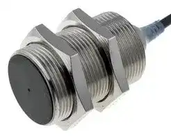


E2A3-M30KS20-WP-B1 2M
Proximity Sensor, Inductive, 20 mm, PNP/SPST-NO, M30, 10 to 32 VDC
- Manufacturer: OMRON INDUSTRIAL AUTOMATION
- Product type: Inductive Proximity Sensors
- SVHC: No SVHC (16-Jan-2020)
- Product Range: E2A3 Series
- Sensing Range Max: 20mm
- Sensor Output Type: PNP / SPST-NO
- Thread Size - Metric: M30
- Supply Voltage DC Max: 32V
- Supply Voltage DC Min: 10V
| Delivery and price | |
|---|---|
| Units per pack | 1 |
| Price | 117.05 € |
| Current stock | 10+ |
| Lead time | 30 days |
## **Cylindrical Proximity Sensor E2A3**

## _High Quality for Extra Long Distance_

- CENELEC triple-distance operation.

- Normally open (NO), and normally closed (NC) models are available.

- Stainless steel and brass housings.

- 360°  angle indicators

## **<READ AND UNDERSTAND THIS CATALOG>**

Please read and understand this catalog before purchasing the products. Please consult your OMRON representative if you have any questions or comments.

## Ordering Information

DC 3-wire Models

a **Size Type** ~~ee~~ **distanceSensing** ~~se~~ **Connection materialBody Thread length Output Operation mode: NO Operation mode: NC** Pre-wired 27 (40) mm[PNP] E2A3-S08KS03-WP-B1 2M E2A3-S08KS03-WP-B2 2M NPN E2A3-S08KS03-WP-C1 2M E2A3-S08KS03-WP-C2 2M ~~|i~~ M8 Shielded 3.0mm ~~|~~ M12 connector Stainless steel (See note.) ~~A~~ 27 (44) mm ~~—~~[PNP] NPN E2A3-S08KS03-M1-C1E2A3-S08KS03-M1-B1 E2A3-S08KS03-M1-C2E2A3-S08KS03-M1-B2 M8 PNP E2A3-S08KS03-M5-B1 E2A3-S08KS03-M5-B2 connector 27 (40) mm ~~|~~ (3-pin) ~~ee a~~ NPN ~~eeee~~ E2A3-S08KS03-M5-C1 ~~es~~ E2A3-S08KS03-M5-C2 Pre-wired 34 (50) mm[PNP] E2A3-M12KS06-WP-B1 2M E2A3-M12KS06-WP-B2 2M NPN E2A3-M12KS06-WP-C1 2M E2A3-M12KS06-WP-C2 2M M12 Shielded 6.0mm Brass M12connector 34 (49) mm[PNP] NPN E2A3-M12KS06-M1-C1E2A3-M12KS06-M1-B1 E2A3-M12KS06-M1-C2E2A3-M12KS06-M1-B2 ~~| —_~~ E2A3-M18KS11-WP-B1 2M E2A3-M18KS11-WP-B2 2M ~~...~~ Pre-wired 39 (60) mm[PNP] NPN E2A3-M18KS11-WP-C1 2M E2A3-M18KS11-WP-C2 2M M18 Shielded 11.0mm Brass M12 connector 39 (54) mm[PNP] NPN E2A3-M18KS11-M1-C1E2A3-M18KS11-M1-B1 E2A3-M18KS11-M1-C2E2A3-M18KS11-M1-B2 ~~| i~~ E2A3-M30KS20-WP-B1 2M E2A3-M30KS20-WP-B2 2M ~~...~~ Pre-wired 44 (65) mm[PNP] NPN E2A3-M30KS20-WP-C1 2M E2A3-M30KS20-WP-C2 2M M30 Shielded 20.0mm Brass M12 connector 44 (59) mm[PNP] NPN E2A3-M30KS20-M1-C1E2A3-M30KS20-M1-B1 E2A3-M30KS20-M1-C2E2A3-M30KS20-M1-B2 ~~| A —_— te —————~~ **Note:** Material specifications for stainless steel housing case: 1.4305 (W.-No.), SUS303 (AISI), 2346 (SS).

Cylindrical Proximity Sensor **E2A3**

1

Connectivity

E2A3 Sensors are available with the following connectors and cable materials:

Pre-wired Models **Connector Models**

Standard cable lengths are 2 m and 5 m. For other cable lengths, please contact your OMRON representative.

Standard connectors: M12, M8 (3-pin) -M1, -M5

Standard cable material: PVC (4-mm dia.) -WP

## Model Number Legend

## **E2A** @ **-** @@@@@ **-** @ **-** @@ **-** @@

**1 2 3 4 5 6 7 8 9 10 11 12 Example:** E2A3-M12KS06-M1-B1 Triple distance, M12, standard barrel, shielded, Sn = 6 mm, M12 connector, PNP-NO E2A3-S08KS03-WP-B1 2M Triple distance, M8 stainless steel, standard barrel, shielded, Sn = 3 mm, pre-wired PVC cable, PNP-NO, cable length = 2 m **1. Basic name 8. Kind of connection** E2A WP: Pre-wired, PVC, 4-mm dia. **2. Sensing technology** M1: M12 connector (4-pin) * Blank: Standard double distance M5: M8 connector (3-pin) 3: Triple distance **9. Power source and output 3. Housing shape and material** B: DC, 3-wire, PNP open collector M: Cylindrical, metric threaded, brass C: DC, 3-wire, NPN open collector S: Cylindrical, metric threaded, stainless steel **10.Operation mode 4. Housing size** 1: Normally open (NO) 08: 8 mm 2: Normally closed (NC) 12: 12 mm **11.Specials (e.g., cable material, oscillating frequency)** 18: 18 mm 30: 30 mm **12.Cable length 5. Barrel length** Blank: Connector Model K: Standard length Numeral: Cable length L: Long body **6. Shield** S: Shielded N: Non-shielded

## **7. Sensing distance**

Numeral: Sensing distance: e.g., 03 = 3 mm, 11 = 11 mm

Cylindrical Proximity Sensor **E2A3**

2

## Specifications

## DC 3-wire Models

|DC 3-wire Models|DC 3-wire Models|||||
|---|---|---|---|---|---|
|**Size**||**M8**|**M12**|**M18**|**M30**|
|**Type**||**Shielded**|**Shielded**|**Shielded**|**Shielded**|
||**Item**|**E2A3-S08KS03-@@-B@**<br>**E2A3-S08KS03-@@-C@**|**E2A3-M12KS06-@@-B@**<br>**E2A3-M12KS06-@@-C@**|**E2A3-M18KS11-@@-B@**<br>**E2A3-M18KS11-@@-C@**|**E2A3-M30KS20-@@-B@**<br>**E2A3-M30KS20-@@-C@**|
|Sensingdistance||3 mm±10%|6 mm±10%|11 mm±10%|20 mm±10%|
|Setting<br>distance|Ambient temp. of<br>−25 to 70°C|0 to 2.1 mm|0 to 4.2 mm|0 to 7.7 mm|0 to 14 mm|
||Ambient temp. of<br>−10 to 60°C|0 to 2.4 mm|0 to 4.8 mm|0 to 8.8 mm|0 to 16 mm|
|Differential travel||20% max. of sensingdistance||||
|Target||Ferrous metal (The sensingdistance decreases with non-ferrous metal.)||||
|Standard sensingobject||9×9×1 mm|18×18×1 mm|33×33×1 mm|60×60×1 mm|
|Response frequency(See note 1.)||700 Hz|350 Hz|250 Hz|80 Hz|
|Power supply voltage<br>(operatingvoltage range)||12 to 24 VDC. Ripple (p-p): 10% max.<br>(10 to 32 VDC)||||
|Current consumption||10 mA max.||||
|Output type||-B models: PNP open collector<br>-C models: NPN open collector||||
|Control output|Load current|200 mA max. (32 VDC max.)||||
||Residual voltage|2 V max.(under load current of 200 mA with cable length of 2 m)||||
|Indicator||Operation indicator(Yellow LED)||||
|Operation mode||-B1/-C1 models: NO<br>-B2/-C2 models: NC<br>For details, refer to the timingcharts.||||
|Protection circuits||Power source circuit re-<br>verse polarity protection,<br>Surge suppressor, Short-<br>circuit protection|Output reverse polarity protection, Power source circuit reverse polarity protec-<br>tion, Surge suppressor, Short-circuit protection|||
|Ambient air temperature||Operating:−25°C to 70°C, Storage:−25°C to 70°C||||
|Temperature influence||±20% max. of sensing distance at 23°C within temperature range of−25°C to 70°C<br>−10% max. to +20% of sensingdistance at 23°C within temperature range of−10°C to 60°C||||
|Ambient humidity||Operating: 35% to 95%, Storage: 35% to 95%||||
|Voltage influence||±1% max. of sensingdistance in rated voltage range±15%||||
|Insulation resistance||50 MΩmin. (at 500 VDC) between current-carryingparts and case||||
|Dielectric strength||1,000 VAC at 50/60 Hz for 1 min between current-carryingparts and case||||
|Vibration resistance||10 to 55 Hz, 1.5-mm double amplitude for 2 hours each in X, Y, and Z directions||||
|Shock resistance||500 m/s2, 10 times each<br>in X, Y, and Z directions|1,000 m/s2, 10 times each in X, Y and Z directions|||
|Standards and listings<br>(See note 2.)||IP67 under IEC 60529<br>EMC under EN60947-5-2||||
|Connection method||-WP models: Pre-wired Models (4-mm dia. PVC cable with length of 2 m)<br>-M1 models: M12 4-pin Connector Models<br>-M5 models: M8 3-pin Connector Models||||
|Weight<br>(packed state)|Pre-wired Models|Approx. 65g|Approx. 85g|Approx. 160g|Approx. 280g|
||Connector Models|M12 Connector Models:<br>Approx. 20g|Approx. 35 g|Approx. 70 g|Approx. 200 g|
|Material|Case|Stainless steel|Brass-nickelplated|||
||Sensingsurface|PBT||||
||Cable|PVC||||
||Clampingnut|Stainless steel|Brass-nickelplated|||


**Note 1.** The response frequency is an average value. Measurement conditions are as follows: standard sensing object, a distance of twice the standard sensing object length between sensing objects, and a set distance of half the sensing distance.

**2.** For USA and CANADA : use class 2 circuit only.

Cylindrical Proximity Sensor **E2A3**

3

Engineering Data

## Operating Range (Typical)

**==> picture [496 x 532] intentionally omitted <==**

**----- Start of picture text -----**<br>
22<br>20<br>18<br>16 Y<br>14 X E2A3-M30KS20<br>12 E2A3-M18KS11<br>10<br>E2A3-M12KS06<br>8<br>E2A3-S08KS03<br>6<br>4<br>2<br>0<br>−30  −20  −10  0  10  20  30<br>Distance Y (mm)<br>Influence of Sensing Object Size and Materials<br>E2A3-S08KS03 E2A3-M12KS06 E2A3-M18KS11<br>3.5 7 12<br>@d @d @d t = 1 mm<br>3.0 X t = 1 mm Iron 6 X t = 1 mm Iron X Iron<br>10<br>2.5 Stainless steel (SUS303) 5 Stainless steel (SUS303) 8 Stainless steel (SUS303)<br>2.0 4<br>Brass 6 Brass<br>Brass<br>1.5 3 Aluminum<br>Aluminum Aluminum<br>Copper 4 Copper<br>1.0 Copper 2<br>0.5 1 2<br>0.0 0 0<br>0  5  10  15  20  25 0  5  10  15  20  25  30 0  10  20  30  40  50<br>Side length of sensing object d (mm) Side length of sensing object d (mm) Side length of sensing object d (mm)<br>E2A3-M30KS20<br>25<br>@d<br>t = 1 mm<br>X<br>20 Iron<br>Stainless steel (SUS303)<br>15<br>Brass<br>10 Aluminum<br>Copper<br>5<br>0<br>0  10  20  30  40  50  60<br>Side length of sensing object d (mm)<br>Sensing distance X (mm)<br>Sensing distance X (mm) Sensing distance X (mm) Sensing distance X (mm)<br>Sensing distance X (mm)<br>**----- End of picture text -----**<br>


## Influence of Sensing Object Size and Materials

Cylindrical Proximity Sensor **E2A3**

4

## Operation

## DC 3-wire Models

PNP Output

|Operation|Operation|Operation|Operation|Operation|Operation|Operation|Operation|Operation|Operation|Operation|Operation|Operation|
|---|---|---|---|---|---|---|---|---|---|---|---|---|
|DC 3-wire Models<br>PNP Output|||||||||||||
|**Operation mode**|**Model**||**Timing chart**||||||**Output circuit**||||
|NO|E2A3-@-@-B1|Sensing<br>object<br>(%)<br>100<br>0<br>Rated<br>sensing<br>distance<br>Sensing area<br>Non-sensing area<br> <br><br>O<br>O<br>O<br>O|||Proximity<br>Sensor<br>N<br>FF<br>N<br>FF<br>Yellow indicator<br>Control output|3<br>1<br>2<br>4<br>3<br>1<br>4<br>Load<br>Brown<br>Black<br>(See note 1.)<br>Blue<br>+V<br>0 V<br>**Note 1:** With M8 Size Models, there is no output reverse<br>polarity protection diode.<br>M12 Connector<br>Pin Arrangement<br>(See note 2.)<br>M8 Connector<br>(3-pin)<br>Pin Arrangement<br>**Note 2:** Terminal 2 of the M12 connector is not used.<br>Proximity<br>Sensor<br>main<br>circuits|||||||
||||||||||||||
||||||||Proxim<br>Sensor<br>main<br>circuits||||||
||||||||||(See<br>ity<br> <br>||||
|||||||||xim<br>nsor<br>in<br>uits|||||
||||||||||||note 1.)|Lo<br>Blue|
||||||||||||||
||||||||||||||
||||||||||||||
||||||||||||||
||||||||||||||
|NC|E2A3-@-@-B2||||Proximity<br>Sensor<br>N<br>FF<br>N<br>FF<br>Yellow indicator<br>Control output|3<br>1<br>2<br>4<br>Load<br>Brown<br>Black<br>(See note 1.)<br>Blue<br>+V<br>0 V<br>**Note 1:** With M8 Size Models, there is no output reverse<br>polarity protection diode.<br>M12 Connector<br>Pin Arrangement<br>(See note 2.)<br>3<br>1<br>4<br>M8 Connector<br>(3-pin)<br>Pin Arrangement<br>**Note 2:** Terminal 4 of the M12 connector is not used.<br>Proximity<br>Sensor<br>main<br>circuits<br>(M8 connector:      )|||||||
||||Non-sensing area||||||||||
||||Sensing<br>object||||||||||
||||(%)<br>1<br>sensing<br>distance||||||||||
||||||||||||||
||||||||||||||
||||||||||||||
||||||||||||||


Cylindrical Proximity Sensor **E2A3**

5

## DC 3-wire Models

NPN Output

|DC 3-wire Models<br>NPN Output|DC 3-wire Models<br>NPN Output|DC 3-wire Models<br>NPN Output|DC 3-wire Models<br>NPN Output|DC 3-wire Models<br>NPN Output|DC 3-wire Models<br>NPN Output|DC 3-wire Models<br>NPN Output|
|---|---|---|---|---|---|---|
|**Operation mode**|**Model**||**Timing chart**|||**Output circuit**|
|NO|E2A3-@-@-C1|Sensing<br>object<br>(%)<br>100<br>0<br>Rated<br>sensing<br>distance<br>Sensing area<br>Non-sensing area<br>Proximity<br>Sensor<br>ON<br>OFF<br>ON<br>OFF<br>Yellow indicator<br>Control output|||Load<br>Brown<br>Black<br>(See note 1.)<br>Blue<br>+V<br>0 V<br>**Note 1:** With M8 Size Models, there is no output reverse<br>polarity protection diode.<br>**Note 2:** Terminal 2 of the M12 connector is not used.<br>Proximity<br>Sensor<br>main<br>circuits<br>3<br>1<br>2<br>4<br>M12 Connector<br>Pin Arrangement<br>(See note 2.)<br>3<br>1<br>4<br>M8 Connector<br>(3-pin)<br>Pin Arrangement||
||||||||
||||||||
||||||||
|NC|E2A3-@-@-C2||||Load<br>Brown<br>Black<br>(See note 1.)<br>Blue<br>+V<br>0 V<br>**Note 1:** With M8 Size Models, there is no output reverse<br>polarity protection diode.<br>**Note 2:** Terminal 4 of the M12 connector is not used.<br>Proximity<br>Sensor<br>main<br>circuits<br>(M8 connector:      )<br>3<br>1<br>2<br>4<br>M12 Connector<br>Pin Arrangement<br>(See note 2.)<br>3<br>1<br>4<br>M8 Connector<br>(3-pin)<br>Pin Arrangement||
||||Non-sensing area||||
||||Sensing<br>object||||
||||(%)<br>1<br>sensing<br>distance||||
||||||||
||||||||
||||||||


Cylindrical Proximity Sensor **E2A3**

6

Dimensions

## **Note:** All units are in millimeters unless otherwise indicated.

## **Pre-wired Models**

**==> picture [93 x 53] intentionally omitted <==**

## E2A3-S08KS03-WP-@@

**==> picture [169 x 65] intentionally omitted <==**

**----- Start of picture text -----**<br>
40<br>26.8<br>13 4 5<br>(See note 1.)<br>M8×1 Indicator (See note 2.)<br>Two, clamping nuts<br>**----- End of picture text -----**<br>


**Note 1.** 4-dia. vinyl-insulated round cable with 3 conductors (Conductor cross section: 0.3 mm[2] ; Insulator diameter: 1.3 mm), Standard length: 2 m

**2.** Operation indicator (yellow)

## E2A3-M12KS06-WP-@@

**==> picture [182 x 72] intentionally omitted <==**

**----- Start of picture text -----**<br>
50.4<br>34<br>17 5.5 12<br>(See note 1.)<br>Indicator (See note 2.)<br>M12×1<br>Two, clamping nuts<br>**----- End of picture text -----**<br>


**Note 1.** 4-dia. vinyl-insulated round cable with 3 conductors (Conductor cross section: 0.3 mm[2] ; Insulator diameter: 1.3 mm), Standard length: 2 m

**2.** Operation indicator (yellow)

## E2A3-M18KS11-WP-@@

**==> picture [185 x 76] intentionally omitted <==**

**----- Start of picture text -----**<br>
59.6<br>39<br>24 6 15<br>(See note 1.)<br>Indicator (See note 2.)<br>M18×1<br>Two, clamping nuts<br>**----- End of picture text -----**<br>


- **Note 1.** 4-dia. vinyl-insulated round cable with 3 conductors (Conductor cross section: 0.3 mm[2] ; Insulator diameter: 1.3 mm), Standard length: 2 m

   **2.** Operation indicator (yellow)

## E2A3-M30KS20-WP-@@

**==> picture [198 x 93] intentionally omitted <==**

**----- Start of picture text -----**<br>
64.6<br>44<br>36 7 15<br>(See note 1.)<br>Indicator (See note 2.)<br>M30×1.5<br>Two, clamping nuts<br>**----- End of picture text -----**<br>


- **Note 1.** 4-dia. vinyl-insulated round cable with 3 conductors (Conductor cross section: 0.3 mm[2] ; Insulator diameter: 1.3 mm), Standard length: 2 m

   **2.** Operation indicator (yellow)

## **M12 Connector Models**

**==> picture [56 x 41] intentionally omitted <==**

## E2A3-S08KS03-M1-@@

**==> picture [164 x 65] intentionally omitted <==**

**----- Start of picture text -----**<br>
43.9<br>26.8<br>13 4 5 M12×1<br>M8×1 Indicator (See note.)<br>Two, clamping nuts<br>**----- End of picture text -----**<br>


**Note:** Operation indicator (yellow LED, 4×90°)

## E2A3-M12KS06-M1-@@

**==> picture [175 x 70] intentionally omitted <==**

**----- Start of picture text -----**<br>
49.2<br>34<br>17 5.5 12<br>M12×1<br>Indicator (See note.)<br>M12×1<br>Two, clamping nuts<br>**----- End of picture text -----**<br>


**Note:** Operation indicator (yellow LED, 4×90°)

## E2A3-M18KS11-M1-@@

**==> picture [176 x 72] intentionally omitted <==**

**----- Start of picture text -----**<br>
54.2<br>39<br>24 6 15<br>M12×1<br>Indicator (See note.)<br>M18×1<br>Two, clamping nuts<br>**----- End of picture text -----**<br>


**Note:** Operation indicator (yellow LED, 4×90°)

E2A3-M30KS20-M1-@@

**==> picture [189 x 83] intentionally omitted <==**

**----- Start of picture text -----**<br>
59.2<br>44<br>36 7 15<br>M12×1<br>Indicator (See note.)<br>M30×1.5 Two, clamping nuts<br>**----- End of picture text -----**<br>


**Note:** Operation indicator (yellow LED, 4×90°)

Cylindrical Proximity Sensor **E2A3**

7

## **M8 Connector Models**

**==> picture [60 x 41] intentionally omitted <==**

## E2A3-S08KS03-M5-@@

**==> picture [166 x 68] intentionally omitted <==**

**----- Start of picture text -----**<br>
39.8<br>26.8<br>13 4 5<br>M8×1<br>Indicator (See note.)<br>M8×1<br>Two, clamping nuts<br>**----- End of picture text -----**<br>


**Note:** Operation indicator (yellow LED, 4×90°)

## **Mounting Hole Cutout Dimensions**

**==> picture [185 x 65] intentionally omitted <==**

**----- Start of picture text -----**<br>
External diameter<br>of Proximity Sensor [Dimension F (mm)]<br>M8 8.5 dia.+0.50<br>F M12M18 18.5 dia.12.5 dia.+0.5+0.500<br>M30 30.5 dia.+0.50<br>**----- End of picture text -----**<br>


Cylindrical Proximity Sensor **E2A3**

8

Safety Precautions

## Precautions for Safe Use

## **WARNING**

**==> picture [32 x 32] intentionally omitted <==**

This product is not designed or rated for ensuring safety of persons. Do not it for such purposes.

## **Power Supply**

Do not impose an excessive voltage on the E2A3, otherwise it may be damaged. Do not impose AC current (100 to 240 VAC) on any DC Model, otherwise it may be damaged.

## **Wiring**

Be sure to wire the E2A3 and load correctly, otherwise it may be damaged.

## **Connection with No Load**

Be sure to insert a load when wiring. Make sure to connect a proper load to the E2A3 during operation, otherwise it may damage internal elements.

## **Do not expose the product to flammable or explosive gases.**

## **Do not disassemble, repair, or modify the product.**

## **Load Short-circuit**

Do not short-circuit the load, or the E2A3 may be damaged.

The E2A3’s short-circuit protection function will be valid if the polarity of the supply voltage is correct and within the rated voltage range.

## Precautions for Correct Use

## **Designing**

## Power Reset Time

The Proximity Sensor is ready to operate within 100 ms after power is supplied. If separate power supplies are connected to the Proximity Sensor and load, be sure to supply power to the Proximity Sensor before supplying power to the load.

## Effects of Surrounding Metal

When mounting the E2A3 within a metal panel, ensure that the clearances given in the following tables are maintained.

**==> picture [244 x 74] intentionally omitted <==**

**----- Start of picture text -----**<br>
l<br>d dia. n<br>m<br>D<br>m l<br>**----- End of picture text -----**<br>


||l<br>m<br>n<br>m<br>D<br>d dia.|l<br>m<br>n<br>m<br>D<br>d dia.|l<br>m<br>n<br>m<br>D<br>d dia.|l<br>m<br>n<br>m<br>D<br>d dia.|l<br>m<br>n<br>m<br>D<br>d dia.|
|---|---|---|---|---|---|
||(Unit: mm)|||||
|**Model**|**Dimension**|**M8**||**M12**||
||**Material of**<br>**surrounding**<br>**metal**|**Ferrous**<br>**metal**|**Non-**<br>**ferrous**<br>**metal**|**Ferrous**<br>**metal**|**Non-**<br>**ferrous**<br>**metal**|
|E2A3<br>Shielded|l|0.5 (*)|2 (*)|2  (*)|1  (*)|
||m|<br> <br>9||<br> <br>18||
||d|24||36||
||D|0.5|2|2|1|
||n|24||36||
||(Unit: mm)|||||
|**Model**|**Dimension**|**M18**||**M30**||
||**Material of**<br>**surrounding**<br>**metal**|**Ferrous**<br>**metal**|**Non-**<br>**ferrous**<br>**metal**|**Ferrous**<br>**metal**|**Non-**<br>**ferrous**<br>**metal**|
|E2A3<br>Shielded|l|4 (*)|2.5 (*)|6 (*)|4 (*)|
||m|33||60||
||d|54||90||
||D|4|2.5|6|4|
||n|54||90||


## Power OFF

The Proximity Sensor may output a pulse signal when it is turned OFF. Therefore, it is recommended that the load be turned OFF before turning OFF the Proximity Sensor.

## Power Supply Transformer

When using a DC power supply, make sure that the DC power supply has an insulated transformer. Do not use a DC power supply with an auto-transformer.

## Mutual Interference

When installing two or more Sensors face-to-face or side-by-side, ensure that the minimum distances given in the following table are maintained.

||||||A<br>B|A<br>B|A<br>B|A<br>B|A<br>B|A<br>B|A<br>B|
|---|---|---|---|---|---|---|---|---|---|---|---|
||||A|||||||||
|||||||||||||
|||||||||||||
|||||||||||||
||**Type**||**Dimension**|**M8**|||||**M12**|**M18**|**M30**|
|E2A3<br>Shielded|||A|25|||||35|70|110|
||||B|20|||||25|45|70|


* Using the nuts provided with the E2A3 allows mounting in the way shown below.

**==> picture [54 x 57] intentionally omitted <==**

Nut provided with E2A3

**==> picture [25 x 6] intentionally omitted <==**

**----- Start of picture text -----**<br>
l = 0 mm<br>**----- End of picture text -----**<br>


Cylindrical Proximity Sensor **E2A3**

9

## **Wiring**

## High-tension Lines

Wiring through Metal Conduit **:**

If there is a power or high-tension line near the cable of the Proximity Sensor, wire the cable through an independent metal conduit to prevent against Proximity Sensor damage or malfunctioning.

## Cable Extension

The standard cable length is less than 200 m.

The tractive force is 50 N.

## **Mounting**

The Proximity Sensor must not be subjected to excessive shock with a hammer when it is installed, otherwise the Proximity Sensor may be damaged or lose its water-resistance.

Do not tighten the nut with excessive force. A washer must be used with the nut.

## **Maintenance and Inspection**

Periodically perform the following checks to ensure stable operation of the Proximity Sensor over a long period of time.

**1.** Check for mounting position, dislocation, looseness, or distortion of the Proximity Sensor and sensing objects.

**2.** Check for loose wiring and connections, improper contacts, and line breakage.

**3.** Check for attachment or accumulation of metal powder or dust.

**4.** Check for abnormal temperature conditions and other environmental conditions.

**5.** Check for proper lighting of indicators (for models with a set indicator).

Never attempt to disassemble or repair the Sensor.

## **Environment**

## Water Resistivity

The Proximity Sensors are tested intensively on water resistance, but to ensure maximum performance and life expectancy, avoid immersion in water and provide protection from rain or snow.

## Operating Environment

Store and operate the Proximity Sensor only within the given specifications.

|e|e||
|---|---|---|
|**Type**||**Torque**|
|M8|Stainless Steel Model|9 N·m|
||Brass Model|---|
|M12||20 N·m|
|M18||60 N·m|
|M30||150 N·m|


## Inrush Current

A load that has a large inrush current (e.g., a lamp or motor) will damage the Proximity Sensor. Connect the load to the Proximity Sensor through a relay.

## **<SUITABILITY FOR USE>**

OMRON shall not be responsible for conformity with any standards, codes, or regulations that apply to the combination of the products in the customer’s application or use of the products.

Take all necessary steps to determine the suitability of the product for the systems, machines, and equipment with which it will be used.

## **<CHANGE IN SPECIFICATIONS>**

Product specifications and accessories may be changed at any time based on improvements and other reasons. Consult with your OMRON representative at any time to confirm actual specifications of purchased product.

Cylindrical Proximity Sensor **E2A3**

10

Cylindrical Proximity Sensor **E2A3**

11

## **Warranties and Limitations of Liabilit y**

## ■ **WARRANTY**

OMRON’s exclusive warranty is that the products are free from defects in materials and workmanship for a period of one year (or other period if specified) from date of sale by OMRON.

OMRON MAKES NO WARRANTY OR REPRESENTATION, EXPRESS OR IMPLIED, REGARDING NON-INFRINGEMENT, MERCHANTABILITY, OR FITNESS FOR PARTICULAR PURPOSE OF THE PRODUCTS. ANY BUYER OR USER ACKNOWLEDGES THAT THE BUYER OR USER ALONE HAS DETERMINED THAT THE PRODUCTS WILL SUITABLY MEET THE REQUIREMENTS OF THEIR INTENDED USE. OMRON DISCLAIMS ALL OTHER WARRANTIES, EXPRESS OR IMPLIED.

## ■ **LIMITATIONS OF LIABILITY**

OMRON SHALL NOT BE RESPONSIBLE FOR SPECIAL, INDIRECT, OR CONSEQUENTIAL DAMAGES, LOSS OF PROFITS OR COMMERCIAL LOSS IN ANY WAY CONNECTED WITH THE PRODUCTS, WHETHER SUCH CLAIM IS BASED ON CONTRACT, WARRANTY, NEGLIGENCE, OR STRICT LIABILITY.

In no event shall responsibility of OMRON for any act exceed the individual price of the product on which liability is asserted.

IN NO EVENT SHALL OMRON BE RESPONSIBLE FOR WARRANTY, REPAIR, OR OTHER CLAIMS REGARDING THE PRODUCTS UNLESS OMRON’S ANALYSIS CONFIRMS THAT THE PRODUCTS WERE PROPERLY HANDLED, STORED, INSTALLED, AND MAINTAINED AND NOT SUBJECT TO CONTAMINATION, ABUSE, MISUSE, OR INAPPROPRIATE MODIFICATION OR REPAIR.

## **A lication Considerations pp**

## ■ **SUITABILITY FOR USE**

THE PRODUCTS CONTAINED IN THIS CATALOG ARE NOT SAFETY RATED. THEY ARE NOT DESIGNED OR RATED FOR ENSURING SAFETY OF PERSONS, AND SHOULD NOT BE RELIED UPON AS A SAFETY COMPONENT OR PROTECTIVE DEVICE FOR SUCH PURPOSES. Please refer to separate catalogs for OMRON’s safety rated products.

OMRON shall not be responsible for conformity with any standards, codes, or regulations that apply to the combination of products in the customer’s application or use of the product.

Take all necessary steps to determine the suitability of the product for the systems, machines, and equipment with which it will be used. Know and observe all prohibitions of use applicable to this product. NEVER USE THE PRODUCT FOR AN APPLICATION INVOLVING SERIOUS RISK TO LIFE OR PROPERTY WITHOUT ENSURING THAT THE SYSTEM AS A WHOLE HAS BEEN DESIGNED TO ADDRESS THE RISKS, AND THAT THE OMRON PRODUCT IS PROPERLY RATED AND INSTALLED FOR THE INTENDED USE WITHIN THE OVERALL EQUIPMENT OR SYSTEM.

## **Disclaimers**

## ■ **CHANGE IN SPECIFICATIONS**

Product specifications and accessories may be changed at any time based on improvements and other reasons. Consult with your OMRON representative at any time to confirm actual specifications of purchased product.

## ■ **DIMENSIONS AND WEIGHTS**

Dimensions and weights are nominal and are not to be used for manufacturing purposes, even when tolerances are shown.

## **ALL DIMENSIONS SHOWN ARE IN MILLIMETERS.**

To convert millimeters into inches, multiply by 0.03937. To convert grams into ounces, multiply by 0.03527.

## Cat. No. D102-E1-01A **OMRON Corporation**

**In the interest of product improvement, specifications are subject to change without notice.**

**Industrial Automation Company**

**Industrial Sensors Division Sensing Devices and Components Division H.Q.** 3-2, Narutani, Nakayama-cho, Ayabe-shi, Kyoto, 623-0105 Japan Tel: (81)773-43-4078/Fax: (81)773-43-4030

Printed in Japan 0305
Updated at June 8, 2026
With a legacy spanning over 80 years, Omron Industrial Automation is a globally recognized leader in the manufacture of advanced industrial control and automation components. Renowned for their reliability and engineering excellence, Omron delivers comprehensive solutions that enhance efficiency, machine safety, and precision across a wide range of manufacturing environments. Our extensive portfolio of Omron products is heavily focused on their industry-leading sensing and switching technologies. We offer a vast selection of sensors, excelling specifically in high-performance proximity sensors, light sensors, and temperature sensors. Complementing this range are robust switching solutions, featuring a deep inventory of power relays, solid-state relays, safety relays, and essential relay accessories designed for demanding operational requirements. Beyond sensing and switching, Omron is highly regarded for its precision automation and process control equipment. Our selection features highly accurate temperature controllers, versatile process controllers, and sophisticated panel displays and instrumentation. To support these fundamental systems, we also supply dependable Omron power supplies, notably AC/DC converters, alongside vital connectivity components like DIN rail terminal blocks to ensure secure, efficient, and complete industrial setups.
About Novapart
Novapart is a B2B electronic component broker specialising in stock shortages and cost reduction. We source hard-to-find parts and identify compliant alternatives across a catalogue of 410,000+ components from 500+ manufacturers.
Learn more →Stock Shortage Specialist
When a component is unavailable, discontinued or has an unacceptable lead time, we tap into our network of vetted European and Asian distributors to source what you need — without compromising on quality or traceability.
Request a quote →Compliant Alternatives
We identify pin-to-pin, electrically equivalent substitutes that meet the same certifications (RoHS, AEC-Q100, REACH) as your original specification — validated against datasheets, not just part numbers. Often at a lower cost.
BOM Analysis service →