


DX80N9X1W-PS50G-NB
PRESSURE SENSOR, 50PSI, GAUGE, 3.6VDC
- Manufacturer: BANNER ENGINEERING
- Product type: Pressure Transducers
- Port Style: 1/4" - 18 NPT
- Product Range: Sure Cross DX80 Series
- Sensor Output: Analogue
- Voltage Rating: 3.6VDC
- Operating Pressure Max: 50psi
- Pressure Measurement Type: Gauge
| Delivery and price | |
|---|---|
| Units per pack | 5 |
| Price | 588.25 € |
| Current stock | 10+ |
| Lead time | 30 days |
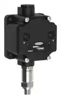
Sure Cross[®] Performance Pressure Sensor Node

## Datasheet

The Sure Cross[®] Performance Series All-in-One Pressure sensor combines a media isolated pressure sensor with the reliable, field-proven, Sure Cross wireless architecture into one package, eliminating the need for ordering multiple components and reducing the physical design of the device. This solution allows monitoring of pneumatic systems, cooling systems, etc. in remote locations without human intervention. The industrial grade, battery-powered device can be used to wirelessly transmit pressure levels to a wireless controller/gateway for remote monitoring of critical systems.

## Benefts

- Provides for the ability to deliver factory automation and IIoT solutions for many applications including, but not limited to monitoring:

   - Water pressure

   - HVAC systems

   - Pneumatic systems

   - Cooling systems/compressors/chillers fluid pressure

   - Hydraulic system pressure

   - Supply tank level via the head pressure

Figure 1. PSx1 with Cable Model

- Eliminate control wires —The Sure Cross wireless system is a radio frequency network with integrated I/O that removes the need for power and control wires

- Reduce complexity —Machine or process reconfiguration made easier; great for retrofit applications

- Deploy easily —Simplify installation on existing equipment to enable deployment in remote and hard-to-access locations where implementing a wired solution would be difficult, impractical, or not cost-effective

- Selectable transmit power levels of 250 mW or 1 Watt for 900 MHz models

- DIP switches for user configuration

- Frequency Hopping Spread Spectrum (FHSS) technology ensures reliable data delivery within the unlicensed Industrial, Scientific, and Medical (ISM) band

- Transceivers provide bidirectional communication between the Gateway and Node, including fully acknowledged data transmission

- Diagnostics allow user defined output settings in the unlikely event of lost RF signal

Figure 2. PS Model with Quick Disconnect

## WARNING:

- Do not use this device for personnel protection

- Using this device for personnel protection could result in serious injury or death.

- This device does not include the self-checking redundant circuitry necessary to allow its use in personnel safety applications. A device failure or malfunction can cause either an energized (on) or deenergized (off) output condition.

## Important:

- Never operate a 1 Watt radio without connecting an antenna

- Operating 1 Watt radios without an antenna connected will damage the radio circuitry.

- To avoid damaging the radio circuitry, never apply power to a Sure Cross[®] Performance or Sure Cross MultiHop (1 Watt) radio without an antenna connected.

## Important:

- Electrostatic discharge (ESD) sensitive device

- ESD can damage the device. Damage from inappropriate handling is not covered by warranty.

- Use proper handling procedures to prevent ESD damage. Proper handling procedures include leaving devices in their anti-static packaging until ready for use; wearing anti-static wrist straps; and assembling units on a grounded, static-dissipative surface.

Original Document 209370 Rev. A

8 March 2019

209370

Sure Cross[®] Performance Pressure Sensor Node

## Models

|Model|Frequency|Inputs|
|---|---|---|
|DX80N9X1W-PS50G|900 MHz ISM Band|0-50 PSI GAUGE Pressure Sensor in the housing port pre-wired to the Node|
|DX80N9X1W-PS50G1||0-50 PSI GAUGE Pressure Sensor with 1 meter cable pre-wired to the Node|
|DX80N9X1W-PS150G||0-150 PSI GAUGE Pressure Sensor in the housing port pre-wired to the Node|
|DX80N9X1W-PS150G1||0-150 PSI GAUGE Pressure Sensor with 1 meter cable pre-wired to the Node|
|DX80N9X1W-PS500S||0-500 PSI SEALED GAUGE Pressure Sensor in the housing port pre-wired to the Node|
|DX80N9X1W-PS500S1||0-500 PSI SEALED GAUGE Pressure Sensor with 1 meter cable pre-wired to the Node|


This model can be configured to supply continuous power. For more information and detailed instructions, refer to the technical note "Configuring for Continuous Switch Power or Host Controlled Switch Power," part number b_3099584.

Integrated battery models are also available without batteries. If you purchase a model without the battery, Banner Engineering recommends using the XENO XL-205F battery or equivalent. For Class I Division 1/Zone 0 and Class I Division 2/Zone 2 environments, only a XENO XL-205F battery is certified.

## Configuration Instructions

## Setting Up Your Wireless Network

To set up and install your wireless network, follow these steps.

Disconnect the power from your Sure Cross devices.

1. Configure the DIP switches of all devices.

2. If your device has I/O, connect the sensors to the Sure Cross devices. If your device does not have I/O, skip this step. 3. Refer to the wiring diagrams to apply power to all devices.

   - For housed models, the Gateway's LED 1 is solid green and the Node's LED 2 flashes red to indicate there is no radio link to the Gateway.

   - For board-level models, the Gateway's LED is solid green and the Node's LED flashes red to indicate there is no radio link to the Gateway.

4. Form the wireless network by binding the Nodes to the Gateway. If the binding instructions are not included in the datasheet, refer to the product manual for binding instructions.

5. Observe the LED behavior to verify the devices are communicating with each other.

   - For housed models, the Gateway's LED 1 is solid green and the Node's LED 1 flashes green to indicate it is communicating with the Gateway.

   - For board-level models, the Gateway's LED is solid green and the Node's LED flashes green to indicate it is communicating with the Gateway.

6. Configure any I/O points to use the sensors connected to the Sure Cross devices.

7. Conduct a site survey between the Gateway and Nodes. If the site survey instructions are not included in this datasheet, refer to the product manual for detailed site survey instructions.

8. Install your wireless sensor network components. If installation instructions are not included in this datasheet, refer to the product manual for detailed installation instructions.

For additional information, including installation and setup, weatherproofing, device menu maps, troubleshooting, and a list of accessories, refer to one of the following product manuals.

- Sure Cross[®] Quick Start Guide: 128185

- Sure Cross[®] Wireless I/O Network Instruction Manual: 132607

- Web Configurator Instruction Manual (used with "Pro" and DX83 models): 134421

- Host Controller Systems Instruction Manual: 132114

## Configure the DIP Switches

Before changing DIP switch positions, disconnect the power. DIP switch changes are not recognized until after power is cycled to the device.

For parameters not set via DIP switches, use the User Configuration Tool (UCT) to make configuration changes. For parameters set using the DIP switches, the DIP switch positions override any changes made using the User Configuration Tool.

## Accessing the Internal DIP Switches

To access the internal DIP switches, follow these steps:

P/N 209370 Rev. A

www.bannerengineering.com - Tel: + 1 888 373 6767

2

Sure Cross[®] Performance Pressure Sensor Node

1. Unscrew the four screws that mount the cover to the bottom housing.

2. Remove the cover from the housing without damaging the ribbon cable or the pins the cable plugs into.

3. Gently unplug the ribbon cable from the board mounted into the bottom housing.

4. Remove the black cover plate from the bottom of the device's cover. The DIP switches are located behind the rotary dials.

After making the necessary changes to the DIP switches, place the black cover plate back into position and gently push into place. Plug the ribbon cable in after verifying that the blocked hole lines up with the missing pin. Mount the cover back onto the housing.

## DIP Switch Settings

The analog configuration pairs the switch power output with the analog input and is programmable using switches four through eight.

|Descriptions|DIP Switches|DIP Switches|DIP Switches|DIP Switches|DIP Switches|DIP Switches|DIP Switches|DIP Switches|
|---|---|---|---|---|---|---|---|---|
||1|2|3|4|5|6|7|8|
|Transmit power level: 1 Watt (30 dBm)|OFF*||||||||
|Transmit power level: 250 mW (24 dBm), DX80 compatibility mode|ON||||||||
|Analog configuration||OFF*|||||||
|Reserved|||OFF*||||||
|Reserved|||||||||
|Sensor switched power voltage: 10 V (to Analog IN 1)||||OFF*|||||
|Sensor switched power voltage: 15 V (to Analog IN 1)||||ON|||||
|Warm-up time 15 milliseconds|||||OFF*||||
|Warm-up time 500 milliseconds|||||ON||||
|Modbus or software configured (overrides DIP switches)||||||OFF|OFF|OFF|
|Sample/report rate 15 minutes||||||OFF|OFF|ON|
|Sample/report rate 5 minutes||||||OFF|ON|OFF|
|Sample/report rate 64 seconds||||||OFF|ON|ON|
|Sample/report rate 16 seconds||||||ON|OFF|OFF|
|Sample/report rate 4 seconds||||||ON|OFF|ON|
|Sample/report rate 2 seconds||||||ON|ON|OFF|
|Sample/report rate 1 second||||||ON|ON|ON|


## Transmit Power Levels

The 900 MHz radios transmit at 1 Watt (30 dBm) or 250 mW (24 dBm). While the Performance radios operate in 1 Watt mode, they cannot communicate with the older 150 mW radios. To communicate with 150 mW radios, operate this radio in 250 mW mode. For 2.4 GHz models, this DIP switch is disabled. The transmit power for 2.4 GHz is fixed at about 65 mW EIRP (18 dBm), making the 2.4 GHz Performance models automatically compatible with older 2.4 GHz models.

## Sensor Switched Power Voltage

The sensor switched power voltage is the power supplied by the Node to the sensor.

## Modbus/Software or DIP Switch Configured

In Modbus/Software Configured mode, use the User Configuration Software or a Modbus command to change the device parameters. DIP switch positions 3 through 8 are ignored. In DIP Switch Configured mode, use the DIP switches to configure the parameters listed in the table.

## Sample and Report Rates

The sample interval, or rate, defines how often the Sure Cross device samples the input. For battery-powered applications, setting a slower rate extends the battery life.

The report rate defines how often the Node communicates the I/O status to the Gateway. For FlexPower[®] applications, setting the report rate to a slower rate extends the battery life.

P/N 209370 Rev. A

www.bannerengineering.com - Tel: + 1 888 373 6767

3

Sure Cross[®] Performance Pressure Sensor Node

## Warm-Up Time

The warm-up time defines how long the device must power up the sensor before a stable sensor reading is taken.

## Wire for Power and I/O

Follow these instructions to wire your device for power, ground, inputs, and outputs. The jumper settings determine which inputs and outputs are active.

|Input Confguration|Jumper Setting|Wiring<br>Terminals|Wiring Diagram Label|Description|
|---|---|---|---|---|
|Reserved|J1 set to 5|||Reserved for future use|
|Reserved|J1 set to 8|1||Reserved for future use|
|||2|GND|Ground|
|||3|SPx|Sensor Switched Power 1 (3.6 to 24 V)|
|Reserved|J2 set to C|||Reserved for future use|
|Analog Voltage Input|J2 set to V|4|Analog IN|Analog Input (0-10 V)|
|||5|GND|Ground|
|Reserved|J3 set to 4|||Reserved for future use|


**==> picture [262 x 155] intentionally omitted <==**

**----- Start of picture text -----**<br>
+ 85 [J1]<br>P22<br>V<br>C [J2]<br>4<br>J3 1<br>3<br>2<br>3<br>4<br>5<br>- 6<br>P30 JP3<br>R6<br>JP1<br>JP2<br>**----- End of picture text -----**<br>


## Analog Input Wiring

**==> picture [134 x 67] intentionally omitted <==**

**----- Start of picture text -----**<br>
SP x<br>sensor<br>Analog IN<br>GND<br>dc common<br>+<br>−<br>+ −<br>**----- End of picture text -----**<br>


Do not exceed analog input ratings for analog inputs. Only connect sensor outputs to analog inputs.

## Bind the DX80 Nodes to the DX80 Gateway and Assign the Node Address

Before beginning the binding procedure, apply power to all the devices. Separate radios by 2 meters when running binding procedure. Put only one Gateway into binding at a time to prevent binding to the wrong Gateway.

1. Enter binding mode on the Gateway.

   - For housed DX80 Gateways, triple-click the right-hand button. LEDs alternatively flash red.

   - For board level DX80 Gateways, triple-click the binding button. LED flashes green and red.

2. Use both of the Node's rotary dials to assign the Node Address defined in the Gateway's datasheet. The left rotary dial represents the tens digit (0 through 4) and the right dial represents the ones digit (0 through 9) of the Node Address.

P/N 209370 Rev. A

www.bannerengineering.com - Tel: + 1 888 373 6767

4

Sure Cross[®] Performance Pressure Sensor Node

3. To enter binding mode on the Node, triple-click button 2.

The Node enters binding mode and locates the Gateway in binding mode. The red LEDs flash alternately. The Node automatically exits binding mode. After the Node is bound, the LEDs are both solid red for a few seconds. The Node cycles its power, then enters Run mode.

4. Label the Node with the assigned address for future references.

5. Repeat steps 2 through 4 for all Nodes that need to communicate to this Gateway.

6. Exit binding mode on the Gateway by single-clicking either button 1 or button 2.

For Gateways with single line LCDs, after binding your Nodes to the Gateway, make note of the binding code displayed under the Gateway's *DVCFG menu, XADR submenu on the LCD. Knowing the binding code prevents having to re-bind all Nodes if your Gateway is ever replaced.

## Bind a DX80 Node to a DXM Gateway and Assign the Node Address

Before beginning the binding procedure, apply power to all the devices. Separate radios by 2 meters when running the binding procedure. Put only one DXM Gateway into binding mode at a time to prevent binding to the wrong Gateway.

Binding Nodes to a Gateway ensures the Nodes only exchange data with the Gateway they are bound to. After a Gateway enters binding mode, the Gateway automatically generates and transmits a unique extended addressing (XADR), or binding, code to all Nodes within range that are also in binding mode. The extended addressing (binding) code defines the network, and all radios within a network must use the same code.

1. Enter binding mode on the DXM radio:

   - a) Use the arrow keys to select the ISM Radio menu on the LCD and press ENTER .

   - b) Highlight the Binding menu and press ENTER .

2. Assign the Node address to the Node.

   - For Nodes without rotary dials: Use the DXM arrow keys to select the Node address to assign to the DX80 Node about to enter binding mode. The DXM assigns this Node address to the next Node that enters binding mode. Only bind one Node at a time.

   - For Nodes with rotary dials: Use the Node's rotary dials to assign a valid decimal Node Address (between 01 and 47). The left rotary dial represents the tens digit (0 through 4) and the right dial represents the ones digit (0 through 9) of the Node Address.

3. Start binding mode on the DXM radio by pressing ENTER on the DXM radio.

4. Enter binding mode on the DX80 Node.

   - For housed radios, triple-click button 2.

   - For board-level radios, triple-click the button.

   - For Nodes without buttons, refer to the Node's datasheet for instructions on entering binding mode.

The left and right red LEDs flash alternately and the Node searches for a Gateway in binding mode. After the Node binds, the LEDs stay solid momentarily, then they flash together four times. The Node automatically exits binding mode.

5. Label the Node with the assigned address number for future reference.

6. Press BACK on the DXM to exit binding mode for that specific Node address.

7. Repeat steps 2 through 5, for as many DX80 Nodes as are needed for your network.

8. When you are finished binding, press BACK on the DXM until you return to the main menu.

## LED Behavior for the Nodes

Nodes do not sample inputs until they are communicating with the Gateway. The radios and antennas must be a minimum distance apart to function properly. Recommended minimum distances are:

900 MHz 150 mW and 250 mW radios: 6 feet

- 900 MHz 1 Watt radios: 15 feet

2.4 GHz 65 mW radios: 1 foot

|LED 1|LED 2|Node Status|
|---|---|---|
|Flashing green||Radio Link Ok|
|Flashing red|Flashing red|Device Error|
||Flashing red, 1 per 3 sec|No Radio Link|


P/N 209370 Rev. A

www.bannerengineering.com - Tel: + 1 888 373 6767

5

Sure Cross[®] Performance Pressure Sensor Node

## Sure Cross[®] User Configuration Software

The User Configuration Software offers an easy way to link I/O points in your wireless network, view I/O register values, and set system communication parameters when a host system is not part of the wireless network. The software runs on any computer with the Windows Vista, Windows 7, Windows 8, or Windows 10 operating system.

Use a USB to RS-485 adapter cable to connect a standalone DX80 Gateway to the computer. For DXM Controllers with an internal DX80 radio, connect a computer to the DXM Controller using a USB or Ethernet connection. Download the most recent revisions of the configuration software from Banner Engineering's website: www.bannerengineering.com/wireless.

The USB to RS-485 adapter cable is not required for the DXM Controller. For standalone DX80 Gateway devices use:

- USB to RS-485 adapter cable model BWA-UCT-900 for 1 Watt radios

- USB to RS-485 adapter cable model BWA-HW-006 for all other radios

## Installing Your Sure Cross[®] Radios

Please refer to one of the following instruction manuals for details about successfully installing your wireless network components.

- DX80 and Performance Wireless I/O Network Instruction Manual: 132607

## Holding Registers

|Modbus Registers|Modbus Registers|EIP Registers|EIP Registers|I/O Type|I/O Range|I/O Range|Holding Register<br>Representation (Dec)|Holding Register<br>Representation (Dec)|
|---|---|---|---|---|---|---|---|---|
|Gateway|Node|Node|||Min.|Max.|Min.|Max.|
|1|1 + (Node# × 16)|0 + (Node# × 8)|Instance 100 / N7||||||
|2|2 + (Node# × 16)|1 + (Node# × 8)||Analog IN 1 (V)|0.0|10.0|0|65535|
|3|3 + (Node# × 16)|2 + (Node# × 8)|||||||
|4|4 + (Node# × 16)|3 + (Node# × 8)|||||||
|5|5 + (Node# × 16)|4 + (Node# × 8)|||||||
|6|6 + (Node# × 16)|5 + (Node# × 8)|||||||
|7|7 + (Node# × 16)|6 + (Node# × 8)||Reserved|||||
|8|8 + (Node# × 16)|7 + (Node# × 8)||Device Message|||||
|9|9 + (Node# × 16)|0 + (Node# × 8)|Instance 112 / N14||||||
||...||||||||
|15|15 + (Node# × 16)|6 + (Node# × 8)||Control Message|||||
|16|16 + (Node# × 16)|7 + (Node# × 8)||Reserved|||||


## Examples

The PS series Node is equipped with a 0 to 5 V dc pressure sensor. The Node register 2 reports this output as a voltage. Use the following equation to change modbus holding register representation into a voltage.

V=Output Voltage in Volts

- X=Analog Input 2 Holding register representation (dec) V = X/6553.5

To interpret this voltage as a pressure reading, multiply it by the following as determined by pressure sensor range.

If you are using the 0-50 PSI model, multiply by 10. If you are using the 0-150 PSI model, multiply by 30. If you are using the 0-500 PSI model, multiply by 100.

If you are using the DX80N9X1W-PS150G with a 0 to 150 PSIG pressure sensor:

V = 13265 (holding register dec) / 6553.5 = ~2.02 V dc PSI = 2.02 x 30 = 60.6 PSIG

If you are using the DX80N9X1W-PS50G with a 0 to 50 PSIG pressure sensor:

V = 13265 (holding register dec) / 6553.5 = ~2.02 V dc PSI = 2.02 x 10 = 20.2 PSIG

If you are using the DX80N9X1W-PS500S with a 0 to 500 PSIS pressure sensor:

V = 13265 (holding register dec) / 6553.5 = ~2.02 V dc PSI = 2.02 x 100 = ~202 PSIS

## Storage and Sleep Modes

Storage Mode (applies to battery-powered models only)—While in storage mode , the radio does not operate. All Sure Cross[®] radios powered from an integrated battery ship from the factory in storage mode to conserve the battery. To wake the device, press and hold button 1 for 5 seconds. To put any FlexPower[®] or integrated battery Sure Cross radio into storage mode, press and

P/N 209370 Rev. A

www.bannerengineering.com - Tel: + 1 888 373 6767

6

Sure Cross[®] Performance Pressure Sensor Node

hold button 1 for 5 seconds. The radio is in storage mode when the LEDs stop blinking, but in some models, the LCD remains on for an additional minute after the radio enters storage mode. After a device has entered storage mode, you must wait 1 minute before waking it.

Sleep Mode (applies to both battery and 10–30 V dc powered models)—During normal operation, the Sure Cross radio devices enter sleep mode after 15 minutes of operation. The radio continues to function, but the LCD goes blank. To wake the device, press any button.

## Install or Replace the Battery (DX80 Models)

To install or replace a lithium "D" cell battery in any integrated housing model, follow these steps.

1. Remove the four screws mounting the face plate to the housing and remove the face plate.

2. Remove the discharged battery (if applicable) by pressing the battery toward the negative terminal to compress the spring. Pry up on the battery’s positive end to remove from the battery holder.

3. Install the new battery. Only use a 3.6 V lithium battery from Xeno, model number XL-205F.

4. Verify the battery’s positive and negative terminals align to the positive and negative terminals of the battery holder mounted within the case. The negative end is toward the spring.

Caution: There is a risk of explosion if the battery is replaced incorrectly.

5. After installing the battery, allow up to 60 seconds for the device to power up.

6. Properly dispose of used batteries according to local regulations by taking it to a hazardous waste collection site, an e- waste disposal center, or other facility qualified to accept lithium batteries.

As with all batteries, these are a fire, explosion, and severe burn hazard. Do not burn or expose them to high temperatures. Do not recharge, crush, disassemble, or expose the contents to water.

- Replacement battery model number: BWA-BATT-001. For pricing and availability, contact Banner Engineering.

## Specifications

## Performance 900 MHz Radio Specifications for Internal Antennas

Radio Range 1 900 MHz, 1 Watt: Up to 9.6 km (6 miles) Antenna Minimum Separation Distance 900 MHz, 1 Watt: 4.57 m (15 ft) Radio Transmit Power 900 MHz, 1 Watt: 30 dBm (1 W) conducted (up to 36 dBm EIRP) Spread Spectrum Technology FHSS (Frequency Hopping Spread Spectrum)

900 MHz Compliance (1 Watt) FCC ID UE3RM1809: FCC Part 15, Subpart C, 15.247 IC: 7044A-RM1809

Link Timeout Gateway: Configurable via User Configuration Tool (UCT) software Node: Defined by Gateway

## Environmental Specifications

Operating Conditions –40 °C to +85 °C (–40 °F to +185 °F) 95% maximum relative humidity (non-condensing) Radiated Immunity: 10 V/m (EN 61000-4-3)

Shock and Vibration IEC 68-2-6 and IEC 68-2-27 Shock: 30g, 11 millisecond half sine wave, 18 shocks Vibration: 0.5 mm p-p, 10 to 60 Hz

Environmental Ratings IEC IP67; NEMA 6 Refer to the Sure Cross[®] Wireless I/O Networks Instruction Manual (p/n 132607) for installation and waterproofing instructions.

Operating the devices at the maximum operating conditions for extended periods can shorten the life of the device.

- 1 Radio range is with the 2 dB antenna that ships with the product. High-gain antennas are available, but the range depends on the environment and line of sight. Always verify your wireless network's range by performing a Site Survey.

P/N 209370 Rev. A

www.bannerengineering.com - Tel: + 1 888 373 6767

7

Sure Cross[®] Performance Pressure Sensor Node

## Pressure Series Model Specifications

## Supply Voltage

3.6 V dc low power option from an internal battery Current Draw at 3.6 V dc

900 MHz, 1 Watt: Approximately 1 mA 900 MHz, 250 mW: Approximately 0.5 mA

Pressure Sensor

Range: 0–50 PSIG, 0–150 PSIG, 0–500 PSIS Proof Pressure: 2× FS Burst Pressure: 3× FS Fatigue Life: > 4 million cycles Output: 0–5 V dc Accuracy: ± 1.4% FS

## Housing

Polycarbonate housing and rotary dial cover; polyester labels; EDPM rubber cover gasket; nitrile rubber, non-sulphur cured button covers Weight: 0.30 kg (0.65 lbs)

Mounting: #10 or M5 (SS M5 hardware included) Max. Tightening Torque: 0.56 N·m (5 lbf·in)

Interface

Two bi-color LED indicators; Two buttons

Sensor Switched Power Outputs One (SP1)

Pressure Sensor Mechanical Pressure Fitting: 1/4"-18NPT Rating: IP65 Housing: 304 Stainless Steel Wetted Material: 316 Stainless Steel

## Performance Curve

**==> picture [345 x 131] intentionally omitted <==**

**----- Start of picture text -----**<br>
Battery Life<br>6<br>5<br>4<br>3<br>2<br>1<br>0<br>1 10 100 1000<br>Sample/Report Rate (seconds)<br>Years<br>**----- End of picture text -----**<br>


|Sample/Report<br>Rate (sec)|Time (years)|
|---|---|
|1|0.58|
|2|1.11|
|4|1.76|
|16|3.26|
|64|4.67|
|300|5.55|
|900|5.57|


## Warnings

Install and properly ground a qualifed surge suppressor when installing a remote antenna system. Remote antenna configurations installed without surge suppressors invalidate the manufacturer's warranty. Keep the ground wire as short as possible and make all ground connections to a single-point ground system to ensure no ground loops are created. No surge suppressor can absorb all lightning strikes; do not touch the Sure Cross[®] device or any equipment connected to the Sure Cross device during a thunderstorm.

Exporting Sure Cross[®] Radios. It is our intent to fully comply with all national and regional regulations regarding radio frequency emissions. Customers who want to re-export this product to a country other than that to which it was sold must ensure the device is approved in the destination country. A list of approved countries appears in the Radio Certifications section of the product manual. The Sure Cross wireless products were certified for use in these countries using the antenna that ships with the product. When using other antennas, verify you are not exceeding the transmit power levels allowed by local governing agencies. Consult with Banner Engineering Corp. if the destination country is not on this list.

## Banner Engineering Corp. Limited Warranty

Banner Engineering Corp. warrants its products to be free from defects in material and workmanship for one year following the date of shipment. Banner Engineering Corp. will repair or replace, free of charge, any product of its manufacture which, at the time it is returned to the factory, is found to have been defective during the warranty period. This warranty does not cover damage or liability for misuse, abuse, or the improper application or installation of the Banner product.

THIS LIMITED WARRANTY IS EXCLUSIVE AND IN LIEU OF ALL OTHER WARRANTIES WHETHER EXPRESS OR IMPLIED (INCLUDING, WITHOUT LIMITATION, ANY WARRANTY OF MERCHANTABILITY OR FITNESS FOR A PARTICULAR PURPOSE), AND WHETHER ARISING UNDER COURSE OF PERFORMANCE, COURSE OF DEALING OR TRADE USAGE. This Warranty is exclusive and limited to repair or, at the discretion of Banner Engineering Corp., replacement. IN NO EVENT SHALL BANNER ENGINEERING CORP. BE LIABLE TO BUYER OR ANY OTHER PERSON OR ENTITY FOR ANY EXTRA COSTS, EXPENSES, LOSSES, LOSS OF PROFITS, OR ANY INCIDENTAL, CONSEQUENTIAL OR SPECIAL DAMAGES RESULTING FROM ANY PRODUCT DEFECT OR FROM THE USE OR INABILITY TO USE THE PRODUCT, WHETHER ARISING IN CONTRACT OR WARRANTY, STATUTE, TORT, STRICT LIABILITY, NEGLIGENCE, OR OTHERWISE.

Banner Engineering Corp. reserves the right to change, modify or improve the design of the product without assuming any obligations or liabilities relating to any product previously manufactured by Banner Engineering Corp. Any misuse, abuse, or improper application or installation of this product or use of the product for personal protection applications when the product is identified as not intended for such purposes will void the product warranty. Any modifications to this product without prior express approval by Banner Engineering Corp will void the product warranties. All specifications published in this document are subject to change; Banner reserves the right to modify product specifications or update documentation at any time. Specifications and product information in English supersede that which is provided in any other language. For the most recent version of any documentation, refer to: www.bannerengineering.com.

For patent information, see www.bannerengineering.com/patents.

© Banner Engineering Corp. All rights reserved
Updated at February 9, 2023
Founded in 1966, Banner Engineering is a globally recognized leader in the design and manufacture of industrial automation products. The company is renowned for developing innovative, high-quality solutions that improve operational efficiency, safeguard personnel, and optimize manufacturing processes across a diverse range of industries. Our extensive selection of Banner Engineering components prominently features their industry-leading sensing technologies. We offer a comprehensive array of precision light sensors engineered for accurate detection and measurement in demanding environments. Complementing this core sensing portfolio is a robust offering of automation signaling devices, including visual signal indicator units and essential accessories, which provide clear and immediate communication of machine status. Beyond primary sensing and indication solutions, our range encompasses critical components for broader process control and machine safety. This includes advanced process controllers, reliable pressure sensors and transducers, and dependable safety relays. Supported by a variety of purpose-built sensor accessories and fiber optic lead assemblies, Banner Engineering delivers the durable, high-performance technologies required to build and maintain sophisticated automated systems.
About Novapart
Novapart is a B2B electronic component broker specialising in stock shortages and cost reduction. We source hard-to-find parts and identify compliant alternatives across a catalogue of 410,000+ components from 500+ manufacturers.
Learn more →Stock Shortage Specialist
When a component is unavailable, discontinued or has an unacceptable lead time, we tap into our network of vetted European and Asian distributors to source what you need — without compromising on quality or traceability.
Request a quote →Compliant Alternatives
We identify pin-to-pin, electrically equivalent substitutes that meet the same certifications (RoHS, AEC-Q100, REACH) as your original specification — validated against datasheets, not just part numbers. Often at a lower cost.
BOM Analysis service →