


DPRCAN0002NG0000A5
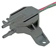
PRESSURE SENSOR, 2IN-H2O, -40 TO 85DEG C
- Manufacturer: HONEYWELL
- Product type: Pressure Transducers
- Product Range: TruStability DPR Series
- Operating Pressure Max: 2Inch-H2O
| Delivery and price | |
|---|---|
| Units per pack | 100 |
| Price | 116.21 € |
| Current stock | 10+ |
| Lead time | 7 days |
_32347489 Issue B_

## DPR SERIES

**TruStability™ Board Mount Pressure Sensors Standard Accuracy, Compensated/Amplified ±1.6 mbar to ±25 mbar | ±160 Pa to ±2.5 kPa | ±0.5 H2O to ±10 inH2O**

## DESCRIPTION

The TruStability™ DPR Series is a piezoresistive silicon pressure sensor offering a ratiometric analog output for reading pressure over the specified full scale pressure span and temperature range. These sensors are fully calibrated and temperature compensated for sensor offset, sensitivity, temperature effects, and non-linearity using an onboard Application Specific Integrated Circuit (ASIC). Calibrated output values for pressure are updated at approximately 1 kHz. The DPR Series is calibrated over the temperature range of -20°C to 70°C [-4°F to 185°F]. The sensor is calibrated for operation from a single power supply of 5.0 Vdc. These sensors measure differential or gage pressures. The robust and durable housing, with its industrystandard mounting configuration, along with a choice of flexible electrical terminations, is designed to withstand tough application environments. The sensors’ internal diagnostic functions detect most internal failures, including burst sensors, and may reduce the need for redundant sensors in the system. The DPR Series is intended for use with non-corrosive, nonionic gases, such as air and other dry gases. Custom calibrations, additional pressure ranges or options to extend the performance of these sensors to include non-corrosive, non-ionic liquids is possible. All products are designed and manufactured according to ISO 9001 standards.

## POTENTIAL INDUSTRIAL APPLICATIONS

- Heating, ventilation, air conditioning (HVAC)

- Variable air volume (VAV) control

- Damper control and duct air flow

- Filter monitoring/clogged filter detection

- Modulated furnace controls

- Indoor air quality

- Leak detection

- Pneumatic control

- Burner control

- Fuel-to-air rationing

- Gas analyzers and meters

- Fume hoods and clean rooms

## FEATURES

- Pressure range: ±1.6 mbar to ±25 mbar |

- ±160 Pa to ±2.5 kPa | ±0.5 inH2O to

- ±10 inH2O

- Pressure types: Differential and gage

- Total Error Band: As low as ±1.25 %FSS depending on pressure range (after auto zero)

- Accuracy: ±0.25 %FSS BFSL (Full Scale Span Best Fit Straight Line)

- Stable offset voltage

- Compensated temperature range: -20ºC to 70ºC [-4ºF to 158ºF]

- Low sensitivity to mounting orientation

- Output: analog voltage

- Overvoltage and reverse polarity protected

- Industry-standard mounting configuration and barbed ports

- Robust and durable package

- Internal diagnostic functions

- RoHS compliant

PORTFOLIO

Honeywell offers a variety of board mount pressure sensors for potential use in medical and industrial applications. Our categories of pressure sensor measurement include absolute, differential, gage or vacuum gage, with unamplified or amplified sensors and covering a wide pressure range. To view the entire product portfolio, click here.

TRUSTABILITY™ BOARD MOUNT PRESSURE SENSORS, DPR SERIES

## TABLE 1. ABSOLUTE MAXIMUM RATINGS[1]

**==> picture [542 x 49] intentionally omitted <==**

**----- Start of picture text -----**<br>
CHARACTERISTIC MIN. MAX. UNIT<br>Supply voltage (Vsupply) -5.0 12.0 Vdc<br>Voltage on output pin -0.3 6.0 Vdc<br>**----- End of picture text -----**<br>


1Absolute maximum ratings are the extreme limits the device will withstand without damage.

## TABLE 2. ENVIRONMENTAL SPECIFICATIONS

**==> picture [542 x 98] intentionally omitted <==**

**----- Start of picture text -----**<br>
CHARACTERISTIC PARAMETER<br>Humidity  0 %RH to 95 %RH, non-condensing<br>Vibration 15 g, 10 Hz to 2 kHz<br>Shock 100 g, 6 ms duration<br>ESD susceptibility 3 kV min, human body model<br>Life [1] 1 million pressure cycles minimum<br>**----- End of picture text -----**<br>


1 Life may vary depending on the specific application in which the sensor is utilized.

## TABLE 3. WETTED MATERIALS[1]

**==> picture [542 x 113] intentionally omitted <==**

**----- Start of picture text -----**<br>
MATERIAL<br>COMPONENT<br>PORT 1 (PRESSURE PORT) PORT 2 (REFERENCE PORT)<br>Ports and covers high temperature polyamide<br>Substrate alumina ceramic<br>Adhesives epoxy, silicone<br>O-Ring silicone rubber<br>Electronic components ceramic, silicon, glass, solder silicon, glass, gold<br>**----- End of picture text -----**<br>


1 Contact Honeywell Customer Service for detailed material information.

## TABLE 4. SENSOR PRESSURE TYPES

**==> picture [542 x 49] intentionally omitted <==**

**----- Start of picture text -----**<br>
PRESSURE TYPE DESCRIPTION<br>Differential Output is proportional to the difference between the pressures applied to each port (Port 1 - Port 2).<br>Gage Output is proportional to the difference between applied pressure and atmospheric (ambient) pressure.<br>**----- End of picture text -----**<br>


## FIGURE 1. TEB COMPONENTS FOR TRUSTABILITY™ BOARD MOUNT PRESSURE SENSORS

**==> picture [213 x 97] intentionally omitted <==**

**----- Start of picture text -----**<br>
Sources of Error<br>Offset<br>Full Scale Span<br>Pressure Non-Linearity<br>Accuracy Total<br>Pressure Hysteresis BFSL Error<br>Pressure Non-Repeatability Band<br>Thermal Effect on Offset<br>Thermal Effect on Span<br>Thermal Hysteresis<br>**----- End of picture text -----**<br>


## FIGURE 2. TRANSFER FUNCTION LIMITS

**==> picture [298 x 156] intentionally omitted <==**

**----- Start of picture text -----**<br>
Compensated Pressure Range<br>100<br>90<br>80<br>70<br>60 Ideal<br>50<br>2% Total<br>40 Error Band<br>30<br>20<br>10<br>0<br>0 1 2 3 4 5 6 7 8 9 10<br>Pmin. Pressure (example unit) Pmax.<br>Output (V) = 0.75 x VPmax. - Psupplymin. x (Pressureapplied - Pmin.) + 0.05 x Vsupply<br>)supply<br>Output (%V<br>**----- End of picture text -----**<br>


2 sensing.honeywell.com

## TRUSTABILITY™ BOARD MOUNT PRESSURE SENSORS, DPR SERIES

**==> picture [542 x 279] intentionally omitted <==**

**----- Start of picture text -----**<br>
TABLE 5. OPERATING SPECIFICATIONS<br>CHARACTERISTIC MIN.  TYP. MAX. UNIT<br>Supply voltage (Vsupply) [1] 4.75 5.0 5.25 Vdc<br>Minimum operating voltage 3.0 — — Vdc<br>Supply current — 2.7 3.5 mA<br>Operating temperature range [2] -40 [-40] — 85 [185] °C [°F]<br>Compensated temperature range [3] -20 [-4] — 70 [158] °C [°F]<br>Startup time (power up to data ready) — — 5 ms<br>Response time — 1 — ms<br>Clipping limits:<br>   upper — — 97.5 %Vsupply<br>   lower 2.5 — —<br>Accuracy [4] — — ±0.25 %FSS BFSL [6]<br>Output resolution — 0.033 — %FSS [6]<br>Orientation sensitivity (±1 g) [5] :<br> <40 mbar | 4 kPa | 20 inH2O — ±0.1 — %FSS [6]<br> <2.5 mbar | 250 Pa | 1 inH2O — ±0.2 —<br>**----- End of picture text -----**<br>


1Ratiometricity of the sensor (the ability of the device output to scale to the supply voltage) is achieved within the specified operating voltage.

> 2 **Operating temperature range:** The temperature range over which the sensor will produce an output proportional to pressure.

> 3 **Compensated temperature range:** The temperature range over which the sensor will produce an output proportional to pressure within the specified performance limits.

> 4 **Accuracy:** The maximum deviation in output from a Best Fit Straight Line (BFSL) fitted to the output measured over the pressure range. Includes all errors due to pressure non-linearity, pressure hysteresis, and non-repeatability.

> 5 **Orientation sensitivity:** The maximum change in offset of the sensor due to a change in position or orientation relative to Earth’s gravitational field.

> 6 **Full Scale Span (FSS):** The algebraic difference between the output signal measured at the maximum (Pmax.) and minimum

(Pmin.) limits of the pressure range. (See Figure 3 for ranges).

Sensing and Internet of Things 3

## TRUSTABILITY™ BOARD MOUNT PRESSURE SENSORS, DPR SERIES

TABLE 6. DPR SERIES AVAILABILITY[1]

**==> picture [526 x 199] intentionally omitted <==**

**----- Start of picture text -----**<br>
|||
|---|---|
|CATALOG LISTING|DESCRIPTION|
|DPR Series, standard accuracy, compensated/amplified, flying leads with 304,8 mm harness|
|DPRCAN0005NG0000A5|length, no gel, 0 inH2O to 5 inH2O pressure range, analog output, 5% to 80% of Vsupply transfer|
|function, 5.0 Vdc supply voltage|
|DPR Series, standard accuracy, compensated/amplified, AMP 3-643814-3 connector with|
|DPRAAN0005NG0000A5|304,8 mm harness length, no gel, 0 inH2O to 5 inH2O pressure range, analog output, 5% to 80%|
|of Vsupply transfer function, 5.0 Vdc supply voltage|
|DPR Series, standard accuracy, compensated/amplified, flying leads with 304,8 mm harness|
|DPRCAN0002NG0000A5|length, no gel, 0 inH2O to 2 inH2O pressure range, analog output, 5% to 80% of Vsupply transfer|
|function, 5.0 Vdc supply voltage|
|DPR Series, standard accuracy, compensated/amplified, AMP 3-643814-3 connector with|
|DPRABN0005NG0000A5|50,8 mm harness length, no gel, 0 inH2O to 5 inH2O pressure range, analog output, 5% to 80%|
|of Vsupply transfer function, 5.0 Vdc supply voltage|
|DPR Series, standard accuracy, compensated/amplified, flying leads with 304,8 mm harness|
|DPRCAN0010NG0000A5|length, no gel, 0 inH2O to 10 inH2O pressure range, analog output, 5% to 80% of Vsupply transfer|
|function, 5.0 Vdc supply voltage|

**----- End of picture text -----**<br>


1 These catalog listings are high volume and may be shipped quickly. Other configurations per Figure 3 are possible; however, minimum order quantity thresholds and NRE may apply. Please consult the factory.

## FIGURE 3. NOMENCLATURE AND ORDER GUIDE

For example, DPRCAN0002NG0000A5 defines a DPR Series, Standard Accuracy, Compensated/Amplified, flying leads, 304,8 mm harness length, no gel, 0 inH2O to 2 inH2O pressure range, analog output type, 5% to 80% of Vsupply transfer function, 5.0 Vdc supply voltage.

**==> picture [541 x 350] intentionally omitted <==**

**----- Start of picture text -----**<br>
|||||||
|---|---|---|---|---|---|
|D  P  R      C       A      N      0  0  0  2  N  G  0  0  0  0      A      5|
|Product Series|Pmax.|referenceunit,|Pmin.|Supply Voltage|
|DPR  compensated/amplifiedStandard accuracy,|
|Electrical Termination|Transfer Function|
|AMP 3-643814-3|A|5% to 80% of Vsupply (analog output)|
|B|10% to 90% of Vsupply (analog output)|
|A|
|Pressure Range|
|Differential|Gage|
|AMP 1-480701-0|01.6MDN1.6|±1.6 mbar|02.5MG0000|0 mbar to 2.5 mbar|
|02.5MDN2.5|±2.5 mbar|0004MG0000|0 mbar to 4 mbar|
|B|&iS|0004MDN004|±4 mbar|0006MG0000|0 mbar to 6 mbar|
|0006MDN006|±6 mbar|0010MG0000|0 mbar to 10 mbar|
|0010MDN010|±10 mbar|0016MG0000|0 bar to 16 mbar|
|0016MDN016|±16 mbar|0025MG0000|0 bar to 25 mbar|
|Flying leads|0025MDN025|±25 mbar|0040MG0000|0 bar to 40 mbar|
|C|
|0160LDN160    ±160 Pa|0250LG0000|0 Pa to 250 Pa|
|0250LDN250    ±250 Pa|0400LG0000|0 Pa to 400 Pa|
|Molex 39-01-4033|
|0400LDN400|±400 Pa|0600LG0000|0 Pa to 600 Pa|
|0600LDN600|±600 Pa|0001KG0000|0 kPa to 1 kPa|
|D|0001KDN001|±1 kPa|01.6KG0000|0 kPa to 1.6 kPa|
|01.6KDN1.6|±1.6 kPa|02.5KG0000|0 kPa to 2.5 kPa|
|02.5KDN2.5|±2.5 kPa|0004KG0000|0 kPa to 4 kPa|
|Harness Length|00.5NDN0.5|±0.5 inH20|0001NG0000|0 inH20 to 1 inH20|
|A|304,8 mm|0001NDN001|±1 inH20|0002NG0000|0 inH20 to 2 inH20|
|B|50,8 mm|0002NDN002|±2 inH20|0005NG0000|0 inH20 to 5 inH20|
|0005NDN005|±5 inH20|0009NGN.75|-0.75 inH20 to 9 inH20|
|Gel|0010NDN010|±10 inH20|0010NG0000|0 inH20 to 10 inH20|
|N|No gel|0014NGN.400020NG0000|-0.40 inH0 inH20 to 20 inH20 to 14 inH20|20|
|5|5.0 Vdc|

**----- End of picture text -----**<br>


4 sensing.honeywell.com

## TRUSTABILITY™ BOARD MOUNT PRESSURE SENSORS, DPR SERIES

**==> picture [542 x 385] intentionally omitted <==**

**----- Start of picture text -----**<br>
TABLE 7. PRESSURE RANGE SPECIFICATIONS FOR ±1.6 MBAR TO ±25 MBAR DIFFERENTIAL AND 0 MBAR TO 2.5 BAR TO<br>0 MBAR TO 40 MBAR GAGE.<br>PRESSURE  PRESSURE  UNIT WORKING OVER BURST  COMMON  TOTAL  TOTAL  LONG-TERM<br>RANGE RANGE PRESSURE [1] PRESSURE [2] PRESSURE [3] MODE  ERROR  ERROR STABILITY,<br>(SEE PRESSURE [4] BAND  BAND AFTER  1000 HR<br>FIGURE 3.) (%FSS) [5] AUTO-ZERO [6] 25°C<br>(%FSS) (%FSS)<br>Differential<br>01.6MDN1.6 -1.6 1.6 mbar 335 675 1000 3450 ±3.5% ±2.5% ±0.5%<br>02.5MDN2.5 -2.5 2.5 mbar 335 675 1000 3450 ±3% ±1.5% ±0.35%<br>0004MDN004 -4 4 mbar 335 675 1000 3450 ±2.5% ±1.25% ±0.35%<br>0006MDN006 -6 6 mbar 335 675 1000 3450 ±2% ±1.25% ±0.35%<br>0010MDN010 -10 10 mbar 375 750 1250 5450 ±2% ±1.25% ±0.25%<br>0016MDN016 -16 16 mbar 375 750 1250 5450 ±2% ±1.25% ±0.25%<br>0025MDN025 -25 25 mbar 435 850 1350 10450 ±2% ±1.25% ±0.25%<br>Gage<br>02.5MG0000 0 2.5 mbar 335 675 1000 3450 ±4% ±3% ±0.5%<br>0004MG0000 0 4 mbar 335 675 1000 3450 ±3% ±1.5% ±0.5%<br>0006MG0000 0 6 mbar 335 675 1000 3450 ±3% ±1.5% ±0.35%<br>0010MG0000 0 10 mbar 335 675 1000 3450 ±2% ±1.25% ±0.35%<br>0016MG0000 0 16 mbar 335 675 1000 3450 ±2% ±1.25% ±0.25%<br>0025MG0000 0 25 mbar 375 750 1250 5450 ±2% ±1.25% ±0.25%<br>0040MG0000 0 40 mbar 375 750 1250 5450 ±2% ±1.25% ±0.25%<br>Pmin. Pmax.<br>**----- End of picture text -----**<br>


> 1 **Working Pressure:** The maximum pressure that may be applied to any port of the sensor in continuous use. This pressure may be outside the operating pressure range limits (Pmin. to Pmax.) in which case the sensor may not provide a valid output until pressure is returned to within the operating pressure range. Tested to 1 million cycles, minimum.

> 2 **Overpressure:** The maximum pressure which may safely be applied to the product for it to remain in specification once pressure is returned to the operating pressure range. Exposure to higher pressures may cause permanent damage to the product. Unless otherwise specified, this applies to all available pressure ports at any temperature within the operating temperature range

> 3 **Burst pressure:** The maximum pressure that may be applied to any port of the product without causing escape of pressure media. Product should not be expected to function after exposure to any pressure beyond the burst pressure.

> 4 **Common mode pressure:** The maximum pressure that can be applied simultaneously to both ports of a differential pressure sensor without causing changes in specified performance.

> 5 **Total Error Band:** The maximum deviation from the ideal transfer function over the entire compensated temperature and pressure range. Includes all errors due to offset, full scale span, pressure non-linearity, pressure hysteresis, repeatability, thermal effect on offset, thermal effect on span, and thermal hysteresis (see Figure 1).

> 6 **Total Error Band after Auto-Zero:** The maximum deviation from the ideal transfer function over the entire compensated pressure range at a constant temperature and supply voltage for a minimum of 24 hours after an auto-zero operation. Includes all errors due to full scale span, pressure non-linearity, pressure hysteresis, and thermal effect on span.

Sensing and Internet of Things 5

TRUSTABILITY™ BOARD MOUNT PRESSURE SENSORS, DPR SERIES

TABLE 8. PRESSURE RANGE SPECIFICATIONS FOR ±160 PA TO ±2.5 KPA DIFFERENTIAL AND 0 PA TO 250 PA TO 0 PA TO 4 KPA GAGE

**==> picture [542 x 360] intentionally omitted <==**

**----- Start of picture text -----**<br>
PRESSURE PRESSURE  UNIT WORKING OVER BURST  COMMON  TOTAL  TOTAL LONG-TERM<br>RANGE RANGE PRESSURE [1] PRESSURE [2] PRESSURE [3] MODE  ERROR  ERROR STABILITY,<br> (SEE PRESSURE [4] BAND  BAND AFTER  1000 HR<br>FIGURE 3.) (%FSS) [5] AUTO-ZERO [6] 25°C<br>(%FSS) (%FSS)<br>Differential<br>0160LDN160 -160 160 Pa 33500 67500 100000 345000 ±3.5% ±2.5% ±0.5%<br>0250LDN250 -250 250 Pa 33500 67500 100000 345000 ±3% ±1.5% ±0.35%<br>0400LDN400 -400 400 Pa 33500 67500 100000 345000 ±2.5% ±1.25% ±0.35%<br>0600LDN600 -600 600 Pa 33500 67500 100000 34500 ±2% ±1.25% ±0.35%<br>0001KDN001 -1 1 kPa 37.5 75 125 545 ±2% ±1.25% ±0.25%<br>01.6KDN1.6 -1.6 1.6 kPa 37.5 75 125 545 ±2% ±1.25% ±0.25%<br>02.5KDN2.5 -2.5 2.5 kPa 43.5 85 135 1045 ±2% ±1.25% ±0.25%<br>Gage<br>0250LG0000 0 250 Pa 33500 67500 100000 345000 ±4% ±3% ±0.5%<br>0400LG0000 0 400 Pa 33500 67500 100000 345000 ±3% ±1.5% ±0.5%<br>0600LG0000 0 600 Pa 33500 67500 100000 345000 ±3% ±1.5% ±0.35%<br>0001KG0000 0 1 kPa 33.5 67.5 100 345 ±2% ±1.25% ±0.35%<br>01.6KG0000 0 1.6 kPa 33.5 67.5 100 345 ±2% ±1.25% ±0.25%<br>02.5KG0000 0 2.5 kPa 37.5 75 125 545 ±2% ±1.25% ±0.25%<br>0004KG0000 0 4 kPa 37.5 75 125 545 ±2% ±1.25% ±0.25%<br>PMIN. PMAX.<br>**----- End of picture text -----**<br>


> 1 **Working Pressure:** The maximum pressure that may be applied to any port of the sensor in continuous use. This pressure may be outside the operating pressure range limits (Pmin. to Pmax.) in which case the sensor may not provide a valid output until pressure is returned to within the operating pressure range. Tested to 1 million cycles, minimum.

> 2 **Overpressure:** The maximum pressure which may safely be applied to the product for it to remain in specification once pressure is returned to the operating pressure range. Exposure to higher pressures may cause permanent damage to the product. Unless otherwise specified, this applies to all available pressure ports at any temperature within the operating temperature range

> 3 **Burst pressure:** The maximum pressure that may be applied to any port of the product without causing escape of pressure media. Product should not be expected to function after exposure to any pressure beyond the burst pressure.

- 4 **Common mode pressure:** The maximum pressure that can be applied simultaneously to both ports of a differential pressure sensor without causing changes in specified performance.

> 5 **Total Error Band:** The maximum deviation from the ideal transfer function over the entire compensated temperature and pressure range. Includes all errors due to offset, full scale span, pressure non-linearity, pressure hysteresis, repeatability, thermal effect on offset, thermal effect on span, and thermal hysteresis (see Figure 1).

> 6 **Total Error Band after Auto-Zero:** The maximum deviation from the ideal transfer function over the entire compensated pressure range at a constant temperature and supply voltage for a minimum of 24 hours after an auto-zero operation. Includes all errors due to full scale span, pressure non-linearity, pressure hysteresis, and thermal effect on span.

6 sensing.honeywell.com

TRUSTABILITY™ BOARD MOUNT PRESSURE SENSORS, DPR SERIES

TABLE 9. PRESSURE RANGE SPECIFICATIONS FOR ±0.5 INH2O TO ±10 INH2O DIFFERENTIAL AND 0 ±0 INH2O TO 20 INH2O GAGE

**==> picture [542 x 323] intentionally omitted <==**

**----- Start of picture text -----**<br>
PRESSURE  PRESSURE  UNIT WORKING OVER BURST  COMMON  TOTAL  TOTAL LONG-TERM<br> RANGE RANGE PRESSURE [1] PRESSURE [2] PRESSURE [3] MODE  ERROR  ERROR  STABILITY,<br> (SEE PRESSURE [4] BAND BAND AFTER  1000 HR<br>FIGURE 3.) (%FSS) [5] AUTO-ZERO [6] 25°C<br>(%FSS) (%FSS)<br>Differential<br>00.5NDN0.5 -0.5 0.5 inH2O 135 270 415 1400 ±4% ±3% ±0.5%<br>0001NDN001 -1 1 inH2O 135 270 415 1400 ±3% ±1.5% ±0.35%<br>0002NDN002 -2 2 inH2O 135 270 415 1400 ±2% ±1.25% ±0.35%<br>0005NDN005 -5 5 inH2O 150 300 500 2200 ±2% ±1.25% ±0.25%<br>0010NDN010 -10 10 inH2O 175 350 500 4200 ±2% ±1.25% ±0.25%<br>Gage<br>0001NG0000 0 1 inH2O 135 270 415 1400 ±4% ±3% ±0.5%<br>0002NG0000 0 2 inH2O 135 270 415 1400 ±3% ±1.5% ±0.35%<br>0005NG0000 0 5 inH2O 135 270 415 1400 ±2% ±1.25% ±0.25%<br>0009NGN.75 -0.75 9 inH2O 135 270 415 1400 ±2% ±1.25% ±0.25%<br>0010NG0000 0 10 inH2O 150 300 500 2200 ±2% ±1.25% ±0.25%<br>0014NGN.40 -0.40 14 inH2O 150 300 500 2200 ±2% ±1.25% ±0.25%<br>0020NG0000 0 20 inH2O 175 350 550 4200 ±2% ±1.25% ±0.25%<br>PMIN. PMAX.<br>**----- End of picture text -----**<br>


> 1 **Working Pressure:** The maximum pressure that may be applied to any port of the sensor in continuous use. This pressure may be outside the operating pressure range limits (Pmin. to Pmax.) in which case the sensor may not provide a valid output until pressure is returned to within the operating pressure range. Tested to 1 million cycles, minimum.

> 2 **Overpressure:** The maximum pressure which may safely be applied to the product for it to remain in specification once pressure is returned to the operating pressure range. Exposure to higher pressures may cause permanent damage to the product. Unless otherwise specified, this applies to all available pressure ports at any temperature within the operating temperature range

> 3 **Burst pressure:** The maximum pressure that may be applied to any port of the product without causing escape of pressure media. Product should not be expected to function after exposure to any pressure beyond the burst pressure.

> 4 **Common mode pressure:** The maximum pressure that can be applied simultaneously to both ports of a differential pressure sensor without causing changes in specified performance.

> 5 **Total Error Band:** The maximum deviation from the ideal transfer function over the entire compensated temperature and pressure range. Includes all errors due to offset, full scale span, pressure non-linearity, pressure hysteresis, repeatability, thermal effect on offset, thermal effect on span, and thermal hysteresis (see Figure 1).

> 6 **Total Error Band after Auto-Zero:** The maximum deviation from the ideal transfer function over the entire compensated pressure range at a constant temperature and supply voltage for a minimum of 24 hours after an auto-zero operation. Includes all errors due to full scale span, pressure non-linearity, pressure hysteresis, and thermal effect on span.

Sensing and Internet of Things 7

TRUSTABILITY™ BOARD MOUNT PRESSURE SENSORS, DPR SERIES

## FIGURE 4. NOMENCLATURE AND ORDER GUIDE

**==> picture [529 x 408] intentionally omitted <==**

**----- Start of picture text -----**<br>
Harness Length Option<br>“A” = 304,8 mm<br>“B” = 50,8 mm<br>ø3,80<br>[0.150] 10,20<br>Electrical Termination “A”: [0.402]<br>3,30 1,8<br>AMP 3-643814-3 Pin 1 [0.130] [0.07]<br> ø3,18 [ ø][2,44]<br>Pin 1: Red          [0.125]         [0.096]<br>Pin 2: Black        ø5,21<br>Pin 3: Green          [0.205]         [0.180] [         ø][4,57]<br>Electrical Termination “B”: Detail “A”<br>AMP 1-480701-0 Pin 1<br>Pin 1: Red<br>Pin 2: Black<br>Pin 3: Green 3,80<br>[0.150] Port 2 / Lo (-)<br>12,70<br>[0.500]<br>See detail “A” Port 2 / Lo (-)<br>Electrical Termination “C”:<br>Flying leads [0.50]12,7<br>Red wire: VSUPPLY<br>Green wire: GroundBlack: Output + [0.39]10,0 [0.059]1,50 [0.26]6,5<br>[0.66]16,7 [1.23]31,2 Port 1<br>Port 1<br>Pin 1 33,38<br>[1.314]<br>Pin 1: Red<br>Pin 2: Black Catalog listing<br>Pin 3: Green<br>55,90<br>[2.201]<br>Wire Color Description Honeywell logo<br>red VSUPPLY MonthYear<br>black output + Date<br>green ground Lot<br>Electrical Termination “D”:<br>MOLEX 39-01-4033<br>**----- End of picture text -----**<br>


8 sensing.honeywell.com

## ADDITIONAL MATERIALS

The following associated literature is available at sensing.honeywell.com:

- Product range guide

- Installation instructions

- CAD Models

## FOR MORE INFORMATION

## WARRANTY/REMEDY

Honeywell warrants goods of its manufacture as being free of defective materials and faulty workmanship during the applicable warranty period. Honeywell’s standard product warranty applies unless agreed to otherwise by Honeywell in writing; please refer to your order acknowledgment or consult your local sales office for specific warranty details. If warranted goods are returned to Honeywell during the period of coverage, Honeywell will repair or replace, at its option, without charge those items that Honeywell, in its sole discretion, finds defective. The foregoing is buyer’s sole remedy and is in lieu of all other warranties, expressed or implied, including those of merchantability and fitness for a particular purpose. In no event shall Honeywell be liable for consequential, special, or indirect damages.

While Honeywell may provide application assistance personally, through our literature and the Honeywell web site, it is buyer’s sole responsibility to determine the suitability of the product in the application.

Specifications may change without notice. The information we supply is believed to be accurate and reliable as of this writing. However, Honeywell assumes no responsibility for its use.

## m WARNING PERSONAL INJURY

DO NOT USE these products as safety or emergency stop devices or in any other application where failure of the product could result in personal injury.

Failure to comply with these instructions could result in death or serious injury.

## m WARNING MISUSE OF DOCUMENTATION

- The information presented in this product sheet is for reference only. Do not use this document as a product installation guide.

- • Complete installation, operation, and maintenance information is provided in the instructions supplied with each product.

Failure to comply with these instructions could result in death or serious injury.

Honeywell Sensing and Internet of Things services its customers through a worldwide network of sales offices and distributors. For application assistance, current specifications, pricing or the nearest Authorized Distributor, visit sensing.honeywell.com or call:

Asia Pacific +65 6355-2828 Europe +44 1698 481481 USA/Canada +1-302-613-4491

## Honeywell Sensing and Internet of Things

9680 Old Bailes Road Fort Mill, SC 29707

www. honeywell.com

32347489-B-EN  |  B  |  01/20 © 2020 Honeywell International Inc. All rights reserved.
Updated at February 9, 2023
Honeywell is a globally recognized leader in the design and manufacture of advanced sensing and switching solutions. Renowned for engineering components that deliver enhanced precision and ruggedness, Honeywell provides essential technologies for demanding applications across critical healthcare, aerospace, and industrial equipment. With a comprehensive portfolio built to address both basic and complex design challenges, the company stands at the forefront of reliable electronic component manufacturing. The core of our Honeywell offering is an extensive selection of high-performance sensors and transducers. This includes a robust lineup of pressure sensors and transducers engineered for accurate fluid and gas measurement in challenging environments. Furthermore, we provide a wide array of temperature sensors and specialized temperature sensing NTC thermistors designed for stable thermal management, alongside precision current sensors and load cells that deliver critical feedback for control systems. Beyond advanced sensing technology, Honeywell’s expertise extends to essential circuit protection and electromechanical components. Our selection encompasses power relays, thermal magnetic circuit breakers, and standard terminal blocks, ensuring safe and efficient power distribution. Whether integrating core components or sourcing specialized accessories, design engineers can rely on Honeywell for uncompromising quality and operational excellence.
About Novapart
Novapart is a B2B electronic component broker specialising in stock shortages and cost reduction. We source hard-to-find parts and identify compliant alternatives across a catalogue of 410,000+ components from 500+ manufacturers.
Learn more →Stock Shortage Specialist
When a component is unavailable, discontinued or has an unacceptable lead time, we tap into our network of vetted European and Asian distributors to source what you need — without compromising on quality or traceability.
Request a quote →Compliant Alternatives
We identify pin-to-pin, electrically equivalent substitutes that meet the same certifications (RoHS, AEC-Q100, REACH) as your original specification — validated against datasheets, not just part numbers. Often at a lower cost.
BOM Analysis service →