
Image not available
Illustrative purposes only

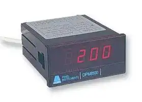
DPM8180-2
Process Meter, DPM8180 Series, DC Current, DC Voltage3.5 Digits, 184 Vac to 253 Vac
⚠️ Reference pricing provided. In case of supply shortages, we will connect you with our trusted procurement partners to ensure your project's continuity.
- Manufacturer: ANDERS ELECTRONICS
- Product type: Digital Panel Meters
- No. of Digits / Alpha:3-1/2; Meter Function:DC Current / DC Voltage; Meter Range:4mA to 20mA, 10mA to 50mA, 1V to 5V, 0V to 10V; Digit Height:14.2mm; Panel Cutout Height:45mm; Panel Cutout Width:92
- SVHC: No SVHC (15-Jun-2015)
- Meter Range: 4mA to 20mA, 10mA to 50mA, 1V to 5V, 0V to 10V
- Digit Height: 14.2mm
- Product Range: -
- Meter Function: DC Current / DC Voltage
- Panel Cutout Width: 92mm
- Supply Voltage Max: 253VAC
- Supply Voltage Min: 184VAC
- Panel Cutout Height: 45mm
- No. of Digits / Alpha: 3-1/2
- Operating Temperature Max: 50°C
- Operating Temperature Min: 0°C
| Delivery and price | |
|---|---|
| Units per pack | 20 |
| Price | 133.7 € |
| Current stock | 10+ |
| Lead time | 30 days |
Datasheet

digital panel meters

## user guide

## DPM8180-2 Process Meter Cé

## **features**

- CE approved and marked

- Large (14.2mm) red LED characters Choice of inputs (4-20mA, 10-50mA, 1-5V, 0-10V) Engineering read-outs e.g. pressure, flow, level Offset and span adjustable

- Adjustable sensor excitation output (5-24V dc) Display hold facility

The  DPM8180 is a low cost, high performance mains powered signal process panel meter. Engineering units such as pressure, flow, temperature and level can be displayed.

It has an adjustable, 5-24V dc (50mA) excitation supply for powering transmitters and active transducers without the need for an external supply.

User calibration is performed by adjusting DIP switches and multi-turn potentiometers to choose the input format and set the corresponding display values.

**==> picture [185 x 22] intentionally omitted <==**

**----- Start of picture text -----**<br>
meters<br>anders DPM8000 series RPM<br>**----- End of picture text -----**<br>


## **ELECTRICAL SPECIFICATION**

|**ELECTRICAL SPECIFICATION**|**ELECTRICAL SPECIFICATION**|**ELECTRICAL SPECIFICATION**|**ELECTRICAL SPECIFICATION**|**ELECTRICAL SPECIFICATION**|
|---|---|---|---|---|
|Range|4-20mA|10-50mA|1-5V|0-10V|
|Input impedance|10 Ohms|10 Ohms|1 MOhm|1 MOhm|
|Maximum input|200mA|200mA|100V|100V|


## **OPERATING SPECIFICATION**

|**OPERATING SPECIFICATION**|**OPERATING SPECIFICATION**|
|---|---|
|Line voltage|115/230V +10%,-20%|
|Line frequency|50/60 Hz|
|Accuracy|+/- 0.1% of  reading+/- 1 digit|
|Temperature coefficient|100 PPM/C|
|Operatingtemperature|0 to 50°C|
|Storage temperature|-10 to 60°C|
|Humidity|below 85% RH|
|Power consumption|6 VA|
|CMRR|110dB|


|**TERMINAL DEFINITIONS**|**TERMINAL DEFINITIONS**|**TERMINAL DEFINITIONS**|
|---|---|---|
|**TERMINAL**|**SYMBOL**|**DESCRIPTION**|
|1|IN HI|Sensor input signal high|
|2|IN LO|Sensor input signal low|
|3|EX V-|Excitation voltage -ve o/p|
|4|HOLD|Connect topin 2 to hold display|
|5|EX V+|Excitation voltage +ve o/p|
|6|n/c|No connection|
|7|230V|AC power source|
|8|115V||
|9|0V||


## ~~|~~ **FIGURE 1       FRONT VIEW (COVER REMOVED) FIGURE 2    CONNECTING A 2 WIRE SENSOR**

Excitation _8 8 8 8_ voltage ON EDG ON EDG Span adjust (P1) 1 2 3 4 5 6 7 8 1 2 3 4 trim (P3) SW1 SW2 Offset trim (P2) —————— Offset Span

## ~~es~~ **FIGURE 3     INSTALLATION DIAGRAM** =| ~~ee~~ **FIGURE 4     DIMENSIONS**

DP8180-2V4 Rev. 4  09/03

**FIGURE 5   PLAN VIEW SHOWING SWITCH  SW3**

## **STEP BY STEP INSTRUCTIONS**

|**STEP BY STEP INSTRUCTIONS**|**STEP BY STEP INSTRUCTIONS**|**STEP BY STEP INSTRUCTIONS**|**STEP BY STEP INSTRUCTIONS**|**STEP BY STEP INSTRUCTIONS**|**STEP BY STEP INSTRUCTIONS**|**STEP BY STEP INSTRUCTIONS**|**STEP BY STEP INSTRUCTIONS**|**STEP BY STEP INSTRUCTIONS**|**STEP BY STEP INSTRUCTIONS**|**STEP BY STEP INSTRUCTIONS**|**STEP BY STEP INSTRUCTIONS**|**STEP BY STEP INSTRUCTIONS**|**STEP BY STEP INSTRUCTIONS**|**STEP BY STEP INSTRUCTIONS**|**STEP BY STEP INSTRUCTIONS**|**STEP BY STEP INSTRUCTIONS**|
|---|---|---|---|---|---|---|---|---|---|---|---|---|---|---|---|---|
|**1**|Remove instrument from protective plastic bag and clip<br>off front cover. Note  location of components as per fig. 1.<br>||||||||||||||||
|**2**|Pull off the three green safety terminals from the rear of<br>the meter. The complete panel meter assembly  can now<br>be removed from  its case by carefully levering the base of<br>the LED display board over the plastic retaining lug while<br>pushing gently on the  terminal pins at the rear.||||||||||||||||
|**3**|<br>Select the required input format from**Table 1**and set the<br>switches on SW3 accordingly (see fig.5). Return the meter<br>assembly to the case andreplace the greenterminals.||||||||||||||||
|**4**|Decide the display range required and set the decimal<br>point using SW1(1 to 3), according to**Table 2**.<br>NOTE<br> If your display is for example 0 - 35.0, then the<br>number of counts (R2) is still 350 for the calculations in<br>step5 below.||||||||||||||||
|**5**|For your chosen display range, apply the formulae from<br>the list below, for your chosen input format. For example,<br>for a 4-20mA input and display range of -100 to 500, the<br>lower reading R1 = -100 (at 4mA) and the upper reading<br>R2 = 500 (at 20mA).<br>Note:the offsetfigure (OF) can have anegativevalue.<br>Input format<br>Offset figure(OF)<br>Span figure(SF)<br>4-20mA<br>OF=(5xR1 - R2)/4<br>SF=(R2 - R1)/160<br>10-50mA<br>OF=(5xR1 - R2)/4<br>SF=(R2 - R1)/400<br>1-5V<br>OF=(5xR1 - R2)/4<br>SF=(R2 - R1)/160<br>0-10V<br>OF= -R1<br>SF=(R2 - R1)/200||||||||||||||||
|**6**|Using your value for OF, set offset switches SW1(5 to 8)<br>according to**Table 4**. Set the polarity switch SW1-4<br>according to the polarity ofOFasindicatedin**Table 3**.||||||||||||||||
|**7**|Using your value for SF, set span switches SW2(1 to 4)<br>according to **Table 5**.||||||||||||||||
|**8**|Make electrical connection to the meter with reference to<br>the Terminal Definition table on page 1.||||||||||||||||
|**9**|Apply an accurate lower input signal, e.g. 4mA, and adjust<br>the offset trim potentiometer (P2) until the display reads<br>your R1 value.||||||||||||||||
|**10**|Apply an accurate upper input signal, e.g. 20mA and<br>adjust the span trim potentiometer (P3) until the display<br>reads your R2 value.||||||||||||||||
|**11**|Repeat steps 9 and 10 until consistent readings are<br>achieved.||||||||||||||||
|**12**|If you require the excitation output , measure the voltage<br>with an external voltmeter across pins  5 and 3 and adjust<br>to the required voltage using potentiometer P3.||||||||||||||||
|**13**|When satisfied with the calibration, remove the input<br>signal,**turn off the**<br> **auxiliary**<br> **a.c. power supply**<br>and<br>remove all the electrical connections.||||||||||||||||
|**14**|Clip the cover back on and insert the meter into the panel<br>cut-out. "Snap"  the mounting clips into the side of the<br>case (refer to installation diagram) and tighten the fixing<br>screws until secure in the panel - do not over tighten!||||||||||||||||
|**15**|With the meter installed in the panel, re-make the<br>electrical connections to the meter with reference to the<br>Terminal Definition Table on page 1. The meter is now<br>ready for use.||||||||||||||||
|**16**|Worked Example<br> Input 4-20mA     Display  0-35.0 Kg<br>Following the step by step instructions the switch<br>positions will be as follows<br>OF=(5xR1 - R2)/4<br>OR=(5x0  - 350)/4<br>= - 87.5<br>SF=(R2 - R1)/160<br>SR=(350 -  0)/160<br>=2.19||||||||||||||||
||sw<br>1-|1<br>sw<br>1-2|sw<br>1-3|sw<br>1-4|sw<br>1-5|sw<br>1-6|sw<br>1-7|sw<br>1-8|sw<br>2-1|sw<br>2-2|sw<br>2-3|sw<br>2-4|sw<br>3-1|sw<br>3-2|sw<br>3-3|sw<br>3-4|
||of|f off|on|off|off|off|off|off|on|off|off|off|on|on|off|off|


**==> picture [179 x 131] intentionally omitted <==**

**----- Start of picture text -----**<br>
SW3<br>Input<br>format<br>9<br>8<br>7<br>6<br>5<br>4<br>A to D Converter Chip<br>3<br>EDG 34 2<br>2 1<br>ON 1<br>**----- End of picture text -----**<br>


**Key to tables:  0 = switch OFF position 1 = switch ON position**

## **TABLE 1   INPUT FORMAT SETTING**

|**TABLE 1   INPUT FORMAT SETTING**|**TABLE 1   INPUT FORMAT SETTING**|**TABLE 1   INPUT FORMAT SETTING**|**TABLE 1   INPUT FORMAT SETTING**|**TABLE 1   INPUT FORMAT SETTING**|
|---|---|---|---|---|
||SW3-1|SW3-2|SW3-3|SW3-4|
|4-20mA<br>10-50mA|1|1|0|0|
|1 - 5V|0|0|1|0|
|0- 10V|0|0|0|1|


## **TABLE 2   DECIMAL POINT SELECT SETTINGS**

|DP1<br>DP2<br>DP3|SW1-1|SW2-2|SW3-3||
|---|---|---|---|---|
||1|0|0||
||0|1|0||
||0|0|1||


## **TABLE 3   POLARITY SELECT**

||Polarity<br>Negative<br>Positive|SW1-4<br>0<br>1|
|---|---|---|


**TABLE 4   OFFSET FIGURE (OF) SETTINGS**

|**TABLE 4OFFSET FIGURE(OF) SETTINGS**|**TABLE 4OFFSET FIGURE(OF) SETTINGS**|**TABLE 4OFFSET FIGURE(OF) SETTINGS**|**TABLE 4OFFSET FIGURE(OF) SETTINGS**|**TABLE 4OFFSET FIGURE(OF) SETTINGS**|
|---|---|---|---|---|
|OffsetFigure|SW1-5|SW1-6|SW1-7|SW1-8|
|0 - 199|0|0|0|0|
|200 - 399|1|0|0|0|
|400 - 599|0|1|0|0|
|600- 799|0|0|1|0|
|800-999|0|0|0|1|
|1000- 1199|1|0|0|1|
|1200- 1399|0|1|0|1|
|1400- 1599|0|0|1|1|
|1600 - 1799|1|0|1|1|
|1800 - 1999|0|1|1|1|
|2000 - 2200|1|1|1|1|


## **TABLE 5   SPAN FIGURE (SF) SETTINGS**

|**TABLE 5   SPAN FIGURE (SF) SETTINGS**|**TABLE 5   SPAN FIGURE (SF) SETTINGS**|**TABLE 5   SPAN FIGURE (SF) SETTINGS**|**TABLE 5   SPAN FIGURE (SF) SETTINGS**|**TABLE 5   SPAN FIGURE (SF) SETTINGS**|
|---|---|---|---|---|
|Span Figure|SW2-1|SW2-2|SW2-3|SW2-4|
|0 - 2|0|0|0|0|
|2 - 4|1|0|0|0|
|4 -6|0|1|0|0|
|6-8|0|0|1|0|
|8- 10|0|0|0|1|
|10- 12|1|0|0|1|
|12 - 14|0|1|0|1|
|14 - 16|0|0|1|1|
|16 - 18|1|0|1|1|
|18- 20|0|1|1|1|
|20- 22|1|1|1|1|


DP8180-2V4 Rev. 4  09/03

DQGHUV HOHFWURQLFV SOF Bayham Place,  London  NW1 OEU   UK Tel: +44 (0)20 7380 8167         Fax: +44 (0)20 7874 1908       www.anders.co.uk
Updated at June 9, 2026
About Novapart
Novapart is a B2B electronic component broker specialising in stock shortages and cost reduction. We source hard-to-find parts and identify compliant alternatives across a catalogue of 410,000+ components from 500+ manufacturers.
Learn more →Stock Shortage Specialist
When a component is unavailable, discontinued or has an unacceptable lead time, we tap into our network of vetted European and Asian distributors to source what you need — without compromising on quality or traceability.
Request a quote →Compliant Alternatives
We identify pin-to-pin, electrically equivalent substitutes that meet the same certifications (RoHS, AEC-Q100, REACH) as your original specification — validated against datasheets, not just part numbers. Often at a lower cost.
BOM Analysis service →