
Image not available
Illustrative purposes only

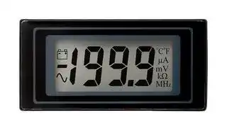
DPM 500
Digital Panel Meter, DC Millivolts, 3-1/2Digits, 0-200mV, 12.5mm Digit Height, 14V
⚠️ Reference pricing provided. In case of supply shortages, we will connect you with our trusted procurement partners to ensure your project's continuity.
- Manufacturer: LASCAR
- Product type: Digital Panel Meters
- No. of Digits / Alpha:3-1/2; Meter Function:DC Voltage; Meter Range:0mV to 200mV; Digit Height:12.5mm; Panel Cutout Height:27mm; Panel Cutout Width:57mm; Supply Voltage Min:7.5V; Su
- SVHC: No SVHC (07-Nov-2024)
- Meter Range: 0mV to 200mV
- Digit Height: 12.5mm
- Product Range: -
- Meter Function: DC Millivolts
- Panel Cutout Width: 57mm
- Supply Voltage Max: 14V
- Supply Voltage Min: 7.5V
- Panel Cutout Height: 27mm
- No. of Digits / Alpha: 3-1/2
- Operating Temperature Max: 50°C
- Operating Temperature Min: 0°C
| Delivery and price | |
|---|---|
| Units per pack | 10 |
| Price | 39.58 € |
| Current stock | 10+ |
| Lead time | 30 days |
Datasheet

DPM 500

3½ Digit LCD Module

The DPM 500 uses advanced components and construction techniques to provide a uniquely compact unit. The meter is in a 40 pin DIL integrated circuit format that can be plugged directly into a DIL socket or panel mounted using the snap in bezel. For single rail use, the DPM500S-BLfeaturesabuiltinnegativerailgenerator,enablingthemetertomeasureasignalreferencedtoitsownpowersupply0V.

- **12.5mm (0.5“) Digit Height**

- **Programmable Decimal Points**

- **Auto-zero**

- **Auto-polarity**

- **200mV d.c. Full Scale Reading (F.S.R.)**

- **Backlit Single Rail Version (DPM 500S-BL)**

- **Annunciators**

## **SCALING**

Two resistors Ra and Rb may be fitted in order to alter the fullscalereading(F.S.R.)ofthemeter-seetable. Meterwillneedre-calibration.

|**Required F.S.R.**<br>2V<br>Note|**Ra**|**Rb**|
|---|---|---|
||910k|100k|
|20V<br>Note|1M|10k|
|200V<br>Note|1M|1k|
|2kV<br>Note|1M|100R|
|200 A|0R|1k|
|2mA|0R|100R|
|20mA|0R|10R|
|200mA|0R|1R|


## **NOTE**

Ensurelink10iscutiffittingRa.

## **SAFETY**

-[+] °C°F A mV k 1={ Ceoeeot. MHz **Stock Number Standard Meter DPM 500 Backlit Single Rail Version DPM 500S-BL** ES **Specification Min. Typ. Max. Unit** ~~ee~~ Accuracy (overall error)* ~~SSes A~~ 0.05 0.1 % (±1 count) ~~Ss~~ Linearity ~~es~~ ±1 count ~~Se~~ Sample rate ~~eS~~ 3 sample/sec Operating temperature range 0 50 °C ~~Se~~ Temperature stability 100 ppm/°C Supply DPM 500 7.5 9 14 V voltage DPM 500S-BL 3.5 5 6.5 ~~|~~ Supply current DPM 500 ~~ee~~ 150 A ~~EC}~~ (not inc. backlighting) DPM 500S-BL 250 ~~|~~ Backlight ~~OL~~ Voltage ~~+ —|~~ 5 V ~~FT EO}~~ (DPM 500S-BL) Current 30 60 mA ~~|~~ Input leakage current (Vin = 0V) ~~—}~~ 1 ~~—++ —~]_s_~~ 10 ~~—}—_~~ pA * To ensure maximum accuracy, re-calibrate periodically. **CONNECTOR SOURCING GUIDE** —— ~~=~~ **METHOD 40 Pin DIL IC Socket**

TocomplywiththeLowVoltageDirective(LVD93/68/EEC),inputvoltagestothemodule’spinsmustnotexceed60Vdc.Ifvoltagestothe measuring inputs do exceed 60Vdc, then fit scaling resistors externally to the module. The user must ensure that the incorporation of the DPM into the user’s equipment conforms to the relevant sections of BS EN 61010 (Safety Requirements for Electrical Equipment for Measuring,ControlandLaboratoryUse).

**DIMENSIONS All dimensions in mm (inches)**

**==> picture [480 x 215] intentionally omitted <==**

**----- Start of picture text -----**<br>
1.1 8.2<br>60.0 (2.36) (0.04) (0.32)<br>a. DPM 500 6.7 (0.26)<br>45.0 (1.77) DPM 500S-BL 12.1 (0.48)<br>b. 4.80 (0.19)<br>Panel cut-out = 57 x 27 (2.24 x 1.06)<br>Display in TEST mode<br>[ —_]| i<br>5.0<br>(0.19) 52 (2.05) a 4.0 (0.16)<br>1 7 12 20 9 11<br>1 7 12 20 DPM 500S-BL ONLY<br>13 12 3 2 5 15 8 ON-BOARD LINKS<br>10 1 4 14<br>40 21 Rb Ra OPTIONAL SCALING<br>40 7 21 RESISTORS<br>1.87 0.5 2.54 REAR VIEW<br>(0.07) (0.02) (0.1)<br>A M XB3 E3<br>REF- COM DP2 DP3<br>V+ V m ° F ° C K AB POL<br>V+ Hz TEST REF HI REF LO REF+ IN HI IN LO BG -5V XDP V- DP1 XG3 BP<br>(1.18)<br>30.0<br>(0.33) (0.98)<br>8.5 24.8<br>(0.63)<br>16.0<br>(0.60)<br>15.2<br>b<br>~ - :<br>- -<br>+ +<br>**----- End of picture text -----**<br>


## **PANEL FITTING**

Fit the bezel to the front of the panel and locate the meter into the bezel from behind. Alternatively the meter and bezel may be assembled before fitting to the front of the panel but care must be taken not to use excessive force. Finally fit the window into the front of the bezel.

**LASCAR ELECTRONICS LTD. LASCAR ELECTRONICS INC. LASCAR ELECTRONICS (HK) LTD. MODULE HOUSE, WHITEPARISH, 4258 WEST 12th STREET, 8th FLOOR, CHINA AEROSPACE CENTRE, 143 HOI BUN WILTSHIRE SP5 2SJ UK ERIE, PA 16505 USA ROAD, KWUN TONG, KOWLOON, HONG KONG TEL: +44 (0)1794 884567 FAX: +44 (0)1794 884616 TEL: +1 (814) 835 0621 FAX: +1 (814) 838 8141 TEL: +852 2389 6502 FAX: +852 2389 6535 E-MAIL: sales@lascar.co.uk E-mail: us-sales@lascarelectronics.com E-mail: saleshk@lascar.com.hk**

## **PIN FUNCTIONS**

1,40. V+ Positivepowersupply. 2-7,12-14,17,38,39 See **SPECIALNOTE: ANNUNCIATORS.** 15. - Inputforthepolarityannunciator. InternallylinkedtoPOL(pin20). Ifthisistobeexternallycontrolled,cutlink11. 16,18,19,22 XB3,E3,AB,XG3. Outputsforuseinauto-rangingapplications. 20. POL Drivefor"-"annunciator. Internallyconnectedbylink11. 21. BP LCDbackplanedrivewaveform.

23. DP3 1.999

24. DP2 19.99 See **SPECIALNOTE: ANNUNCIATORS.** 25. DP1 199.9 26. V- Negativepowersupply. NotethatiftheDPM500S-BL isbeingused,thevoltagebetweenV+andV-mustnotexceed6.5V. 27. XDP Connecttorequiredannunciators/DPs(seenote). 28. -5V Outputfromnegativerailgeneratorcircuit. ThisoutputisaninversionofV+(DPM500SBLONLY). 29. BG Inputforbandgapreference.(1.22Vnom). 30. INLO Negativemeasuringinput. Analogueinputsmustbenocloserthan1Vtoeitherthepositiveornegativesupply. Thenegative 31. INHI Positivemeasuringinput. supplyoftheDPM500S-BLisgeneratedinternallyandmirrorsthepositivesupplyvoltage. 32. COM ThegroundfortheanaloguesectionoftheA/Dconverter,heldactivelyat2.8V(nom)belowV+. COMmustnotbeallowedtosink excessivecurrent(>100 A)byconnectingitdirectlytoahighervoltage.

33. REFNegativeoutputfrominternalreference. 34. REF+ Positiveoutputfrominternalreference. 35. REFLO Negativeinputforreferencevoltage. 36. REFHI Positiveinputforreferencevoltage. 37. TEST ConnectingthispintoV+turnsonthesegmentsasillustrated. ItshouldnotbeoperatedformorethanafewsecondsastheDC voltageappliedtotheLCDmay"burn"thedisplay. Thispinisnominallyat5VbelowV+andisthegroundforthedigitalsection of themeter,itcanbeusedasanegativesupplytopowerexternallogicuptoamaximumof1mA.

40. V+/CLK NormallytiedtoV+viaLink12butcanbeusedtooverridetheinternaloscillatorandcontrolthesampleratebycuttingLink12and makingLink13.

**LED BACKLIT VERSIONS:** Apply 5V DC to the backlight tab on the side of the meter. Typical current is 30mA. For higher voltages, fit a resistor in series. E.g.For9Vuse150R. Maximumcurrent=60mA.

**==> picture [526 x 381] intentionally omitted <==**

**----- Start of picture text -----**<br>
SPECIAL NOTE: ANNUNCIATORS: The DPM annunciators (DPs, °C, etc.) can be displayed by connecting them to XDP. However as these<br>annunciators are normally ‘floating’, under certain conditions they may appear when not wanted. To suppress unwanted annunciators, link them to<br>the backplane (BP). If the annunciators are being switched, connect them via a 1M resistor to the BP (pin 21). The annunciators will then operate<br>normallywhenconnectedtoXDP.EnsurethatanannunciatorisnotconnecteddirectlytotheXDPandBPatthesametime.<br>VARIOUS OPERATING MODES<br>ON-BOARD LINKS: In order to quickly and easily change operating modes for Normally Normally<br>different applications, the meter has several "on-board links". They are designed SHORTEDCut to OPENSolder to<br>to be easily opened(cut) or shorted (soldered). OPEN SHORT<br>Do not connect more than one meter to the same power supply if the meters cannot<br>use the same signal ground. Taking any input beyond the power supply rails will<br>damage the meter.<br>V+ V+ V+<br>1 1 1<br>V+ V+ V+<br>+ 31 IN HI<br>31 31<br>+ IN HI ±200mV 14V max + IN HI<br>±200mV - 30 IN LO 7V min ±200mV<br>- 30 IN LO 0V - 30 IN LO<br>V- 1V min V- V-<br>26 26 26<br>doa¢ V- V- 0V<br>Links 1, 2, 3 & 4 SHORTED. Links 1, 3 & 4 SHORTED. Links 1, 3 & 4 SHORTED.<br>Measuring a floating voltage Split supply operation (DPM 500). Measuring a single ended input<br>source of 200mV full scale. referenced to supply (DPM 500S-BL).<br>1 V+ 1 V+ IIN 1 V+<br>V+ 31 V+ V+<br>31 IN HI + IN HI 31 IN HI<br>R V1 - 30 IN LO 220K<br>30 IN LO + 36 REF HI 6R2 30 IN LO<br>R= [0.2] V2 - 35 REF LO 5K 32 COM<br>IFSR V- V- V-<br>= 26 V- 0 26 V- IOUT © 26V-<br>Links 1, 2, 3, 4 SHORTED. Links 1, 3 & 4 SHORTED.<br>Measuring current Measuring the ratio of two voltages. Measuring 4-20mA to read 0-999<br>(supply MUST be isolated). Reading = 1000 V1/V2 (supply must be isolated).<br>50mV< V2<200mV<br>V1<2V2.<br>**----- End of picture text -----**<br>


_**Specifications liable to change without prior warning**_

**DPM 500 Issue 11 06/2010 S.L.**

**Applies to DPM 500/7**
Updated at June 9, 2026
About Novapart
Novapart is a B2B electronic component broker specialising in stock shortages and cost reduction. We source hard-to-find parts and identify compliant alternatives across a catalogue of 410,000+ components from 500+ manufacturers.
Learn more →Stock Shortage Specialist
When a component is unavailable, discontinued or has an unacceptable lead time, we tap into our network of vetted European and Asian distributors to source what you need — without compromising on quality or traceability.
Request a quote →Compliant Alternatives
We identify pin-to-pin, electrically equivalent substitutes that meet the same certifications (RoHS, AEC-Q100, REACH) as your original specification — validated against datasheets, not just part numbers. Often at a lower cost.
BOM Analysis service →