


DP-101A-M-P
Pressure Sensor, 100 kPa, PNP Open Collector, Gauge, 24 VDC, M5, 30 mA
- Manufacturer: PANASONIC
- Product type: Pressure Transducers
- Port Style: M5
- Product Range: DP-100 Series
- Sensor Output: PNP Open Collector
- Supply Current: 30mA
- Voltage Rating: 24VDC
- Operating Pressure Max: 100kPa
- Pressure Measurement Type: Gauge
| Delivery and price | |
|---|---|
| Units per pack | 1 |
| Price | 103.68 € |
| Current stock | 10+ |
| Lead time | 7 days |
## For gas “™
## Upgrade 1
## **Improved visibility in Digital Display**
**New DP-100 series**
## Upgrade 2
## **Addition of analog current output capability to multifunctional models**
## Upgrade 3
## **14% lower power consumption (during normal operation)**
**New DP-100 series**
## Upgrade 4
**Addition of a reverse polarity protection circuit to the transistor output circuit**
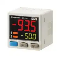
_**Dual Display**_ + _**Direct setting**_
## **A new global standard**
## _**“Current value” and “threshold value” can be checked at the same time!**_
**==> picture [78 x 11] intentionally omitted <==**
**----- Start of picture text -----**<br>
Current value<br>**----- End of picture text -----**<br>
**==> picture [414 x 329] intentionally omitted <==**
**----- Start of picture text -----**<br>
Threshold value<br>Main display<br>Comparative Output 1 operation indicator<br>Comparative Output 2 operation indicator —fs Sub display<br>Work as analog voltage output operation<br>indicator in Multi-function type<br>( Mode selection key | Decrement key<br>Increment key<br>eT<br>Previous model with single display<br>1.181 in square square _<br>-91.8<br>Take a note on current value Operate MODE key Adjust threshold value Return to RUN operation<br>DP-100 with dual display<br>Simply press a button during RUN operation Man-hours reduced by 3<br>/4<br>Direct setting<br>Threshold value setting method<br>**----- End of picture text -----**<br>
## **Dual display allows direct setting of threshold value**
Equipped with a 30 mm 1.181 in square square compact-sized dual display. The current value and the threshold value can be checked at the same time, so the threshold value can be set and checked smoothly without switcing to another screen mode. ON / OFF operations still continue while the threshold values are being set, so setting to the same sensitivity as dial control-type sensors is possible. Key lock function is equipped as well.
## **3-color display (Red, Green, Orange)**
The main display changes color in line with changes in the status of output ON / OFF operation, and it also changes color while setting is in progress. The sensor status can therefore be understood easily, and operating errors can be reduced.
## **Readable digital display!**
Alphanumeric indication in 12 segments is used. This improved visual checking.
**==> picture [213 x 65] intentionally omitted <==**
**----- Start of picture text -----**<br>
OFF: Green (or Red) ON: Red (or Green) SET: Orange<br>Main<br>Display<br>ae<br>During normal operation During setting<br>**----- End of picture text -----**<br>
2
## **Copy function helps operation to be accurate and quick**
## **Copy function reduces man-hours and human error**
Sensors can be connected to a master sensor one by one, and a copy of the setting details for the master sensor can be transmitted as data to other sensors. If making the same settings for multiple sensors, this prevents setting errors among other sensors and in addition, when machinery design are changed, there would be less change in work orders.
**==> picture [492 x 574] intentionally omitted <==**
**----- Start of picture text -----**<br>
Setting details can be copied.<br>Copying via wiring Master sensor Power supply Slave sensor<br>+V +V<br>— ae<br>0 V PCN 0 V<br>Comparative Comparative<br>output 1 output 1<br>~ = Comparative Comparative<br>ES output 2 output 2<br>Details transmitted<br>1<br>Details received<br>~~ _)<br>Note: Settings cannot be copied from the new version (Ver. 2) to the old version.<br>However, settings can be copied from the old version to the new version (Ver. 2).<br>Advantage 1 Setting man-hours are reduced and sensor setting time is shortened.<br>Number of pressure sensor: 1 unit per 1 equipment, 4 equipment per 1 line<br>5 minutes<br>4th equipment:<br>approx.<br>Reduction<br>3rd equipment: 5 minutes of lead time<br>approx.<br>=><br>The setting details for the master sensor are<br>2nd equipment: 5 minutes retained, so continuous copying is possible.<br>approx. 20 seconds 3rd equipment:4th equipment: For 2nd and subsequent lines, the data<br>approx. 2nd equipment: transmission time only is required.<br>1st equipment:<br>5 minutes Master 5 minutes<br>1st equipment: approx. sensor approx. 20 seconds 3rd equipment:4th equipment:<br>approx. 2nd equipment:<br>li | 1st equipment: BS<br>Sensor setting time: Sensor setting time: Sensor setting time:<br>20 minutes approx. 5 minutes 20 seconds approx. 20 seconds approx.<br>Previously DP-100 , 1st line DP-100 , 2nd line<br>I<br>Advantage 2 Human operating error is reduced.<br>Details copied<br>**----- End of picture text -----**<br>
Because all details are copied automatically, problems as a result of human error can be prevented.
Instruction manuals can be updated easily when changes are made to equipment design.
3
## **Setting is smooth and easy**
## **The sensor’s setting operation mode has a 3-level configuration to suit the frequency of use.**
## **RUN mode**
The setting levels are clearly separated into “RUN mode” for operation settings that are carried out daily, “MENU SETTING mode” for basic settings, and “PRO mode” for special and detailed setting. These make setting operations easy to understand and easy to carry out.
Settings such as threshold value adjustment and key lock operation can be carried out while the sensor is operating.
**==> picture [340 x 94] intentionally omitted <==**
**----- Start of picture text -----**<br>
Simple setting RUN mode : ‘ [a (ws<br>}<br>\ MENU SETTING mode J<br>\ Panasonic P<br>Special and a \ PRO mode ——_—_—_—_—_ —_ OT<br>detailed setting<br>**----- End of picture text -----**<br>
**==> picture [85 x 7] intentionally omitted <==**
**----- Start of picture text -----**<br>
MENU SETTING mode<br>**----- End of picture text -----**<br>
Basic settings such as output mode setting and NO / NC switching can be carried out.
**==> picture [42 x 6] intentionally omitted <==**
**----- Start of picture text -----**<br>
PRO mode<br>**----- End of picture text -----**<br>
High-level function settings such as hysteresis adjustment and the copy function can be carried out.
## **Displayed in orange while setting is in progress**
The display appears in red and green during RUN operation, but it changes to orange while setting is in progress, so that the sensor status can be viewed at a glance.
**==> picture [220 x 11] intentionally omitted <==**
**----- Start of picture text -----**<br>
RUN operation RUN mode<br>**----- End of picture text -----**<br>
**While setting MENU SETTING mode PRO mode** 2 wa Orange while setting is in progress
**==> picture [308 x 10] intentionally omitted <==**
**----- Start of picture text -----**<br>
or<br>1<br>**----- End of picture text -----**<br>
Red or green when output is ON / OFF
**Default settings that can be used straight away** Easy-to-use default settings are provided for applications that are used frequently by pressure sensors. The default settings for low pressure types are ideal for suction confirmation applications, and those for high pressure types are ideal for checking reference pressure.
**Buttons with good clicking touch** The buttons have a good clicking touch, allowing smooth setting.
**==> picture [244 x 82] intentionally omitted <==**
**----- Start of picture text -----**<br>
Low pressure type High pressure type<br>Comparative output 1 Comparative output 1<br>Hysterisys 3digits Ideal for Hysterisys 3digits<br>ON checking<br>suction<br>| fa - | JH Ideal for<br>OFF 1 referencechecking<br>pressure<br>–100 kPa –50 kPa 0 kPa 0 MPa 0.5 MPa 1 MPa<br>**----- End of picture text -----**<br>
**The clicking feeling is transmitted even through gloves.**
## **Reset function**
If a problem ever occurs with the sensor settings, they can be reset to the default settings.
4
## **Full range of performance and functions in a compact body**
## **All lineup models are compound pressure types**
No sensor settings are required to switch between positive pressure and negative pressure, so that the number of registered part numbers can be decreased.
**==> picture [228 x 97] intentionally omitted <==**
**----- Start of picture text -----**<br>
<For low pressure><br>Ideal for applications such<br>as suction. No mis-<br>operations due to vacuum <For high pressure><br>breakdown occur. Ideal for applications such<br>as checking reference<br>–100 kPa 0 kPa 100 kPa pressure. Can also be used<br>For low for simple suction.<br>DP-101 ;<br>pressure<br>For high<br>DP-102<br>pressure<br>**----- End of picture text -----**<br>
**==> picture [18 x 6] intentionally omitted <==**
**----- Start of picture text -----**<br>
1 MPa<br>**----- End of picture text -----**<br>
## **High performance accomplished** fF **Low pressure type**
The low pressure type displays measurements in 0.1 kPa at a resolution of 1/2,000 and has a response time of 2.5 ms (variable up to 5,000 ms), ±0.5 % F.S. temperature characteristics and ±0.1 % F.S. repeatability, achieving high detection performance.
**Resolution: 1/2,000 Response time: 2.5 ms Temperature characteristics: ±0.5 % F.S. Repeatability: ±0.1 % F.S.**
**Displays measurements in 0.1 kPa**
**Standard type** |
## **Equipped with independent dual output**
Equipped with two independent comparative outputs, and separate sensing modes can be selected for each of them. Since there are two comparative outputs, one of the comparative outputs can even be used for alarm output. In addition, output, which is not being used, can be disabled.
## **Vacuum breakdown can also be notified during suction applications!**
**==> picture [161 x 94] intentionally omitted <==**
**----- Start of picture text -----**<br>
ON<br>Comparative output 1<br>EASY mode Suction checking<br>OFF<br>ON<br>Comparative output 2<br>EASY mode<br>OFF<br>=“ | Vacuum breakdown checking<br>–100 kPa P-1 0 kPa P-2<br>**----- End of picture text -----**<br>
**Reference pressure alarm output is possible during reference pressure checking!**
**==> picture [244 x 94] intentionally omitted <==**
**----- Start of picture text -----**<br>
Comparative output 1 ON Reference<br>Hysteresis pressure<br> mode checking<br>OFF<br>Alarm output<br>ON<br>Comparative output 2<br>EASY mode<br>OFF<br>GA<br>0 kPa Lo-1 Hi-1 P-2<br>**----- End of picture text -----**<br>
**Three output modes are suitable for a wide range of applications**
**1**
## **EASY mode**
**==> picture [216 x 72] intentionally omitted <==**
**----- Start of picture text -----**<br>
This mode is used for comparative output ON / OFF control.<br>H (Hysteresis)<br>P<br>0<br>ON<br>Comparative output OFF H: Fixed<br>Pressure<br>**----- End of picture text -----**<br>
Notes: 1) Hysteresis can be fixed to one of eight different levels. 2) “ ” appears in the sub display for comparative output 1, and “ ” appears for comparative output 2.
**2**
## **Hysteresis mode**
This mode is used for setting comparative output hysteresis to the desired level and for carrying out ON / OFF control.
**==> picture [244 x 208] intentionally omitted <==**
**----- Start of picture text -----**<br>
Hi<br>H (Hysteresis)<br>Lo<br>0<br>ON<br>Comparative output OFF H: 1 digit or more<br>Note: “ ” or “ ” appears in the sub display for comparative<br>output 1, and “ ” or “ ” appears for comparative output 2. He? bad<br>3 Window comparator mode<br>This mode is used for setting comparative output ON and OFF<br>at pressures within the setting range.<br>H (Hysteresis)<br>Het ba Hi wt<br>H (Hysteresis)<br>Lo<br>0 Z<br>ON<br>Comparative output OFF H: Fixed<br>Notes: 1) Hysteresis can be fixed to one of eight different levels.<br>2) “ ” or “ ” appears in the sub display for comparative het band<br>output 1, and “ ” or “ ” appears for comparative output 2. Me-d Love<br>Pressure<br>Pressure<br>**----- End of picture text -----**<br>
5
## **Equipped with auto-reference / remote zero-adjustment functions, More precise pressure management is achieved with a minimum of effort**
**==> picture [75 x 21] intentionally omitted <==**
**----- Start of picture text -----**<br>
Multi-function type<br>[<br>**----- End of picture text -----**<br>
If the reference pressure of the device changes, two functions are selectable. One is auto-reference function, which partially shift the comparative output judgment level by the amount that the reference pressure shifts. The other is remote zero-adjustment function, which can reset the display value to zero via external input. These functions are ideal for places where the reference pressure fluctuates wildly, or where fine settings are required.
**==> picture [242 x 383] intentionally omitted <==**
**----- Start of picture text -----**<br>
Do Without auto-reference and remote zero-adjustment functions<br>Comparative output: Window comparator mode<br>Hi-1 30, Lo-1 25<br>OO<br>Fixed set value<br>40<br>NG?<br>30<br>Leak threshold level<br>OK<br>25<br>20<br>NG?<br>15<br>Variation in the filling pressure<br>Trial 1<br>Trial 2<br>Trial 3<br>Pressure<br>0 Time<br>Because the threshold level is fixed for conventional pressure sensors,<br>changes in the reference pressure result in wrong decisions.<br>With remote zero-adjustment function applied<br>Comparative output: Window comparator mode<br>Hi-1 0, Lo-1 – 5<br>Sets the absolute threshold level<br>Remote zero-adjustment input<br>The display is forced to “0”, and only the<br>filling pressure drop range is displayed.<br>30 0<br>25 – 5 OK<br>20<br>Threshold level after applying<br>15 remote zero-adjustment input<br>Threshold level before applying<br>remote zero-adjustment input<br>Trial 1<br>Pressure 0 WA Displayed when remote zero-<br>–5 adjustment input is applied<br>Time<br>**----- End of picture text -----**<br>
**==> picture [222 x 183] intentionally omitted <==**
**----- Start of picture text -----**<br>
With auto-reference function applied<br>Comparative output: Window comparator mode<br>Hi-1 0, Lo-1 – 5<br>Sets the absolute threshold level<br>Auto-reference input<br>The display remains at “30” and<br>only the threshold level is changed.<br>30 ef ee<br>25 OK<br>20<br>Threshold level after applying<br>15 auto-reference input<br>Threshold level before applying<br>auto-reference input<br>Trial 1<br>Pressure 0<br>–5 Auto-reference input value<br>Time<br>**----- End of picture text -----**<br>
When auto-reference input is applied, the reference pressure “30” is added to the threshold level. If the reference pressure changes to “20” or “40”, the auto-reference input compensates for this every time by changing the threshold level, so any variation in the filling pressure can be ignored.
When remote zero-adjustment input is applied, the reference pressure is forced to “0”. If the reference pressure changes to “20” or “40”, the remote zero-adjustment input adjusts the reference pressure to “0” every time the reference pressure changes, so any variation in the filling pressure can be ignored.
## **Peak hold and Bottom hold functions**
The peak values and bottom values for fluctuating pressures can be displayed using the dual display.
**==> picture [169 x 49] intentionally omitted <==**
**----- Start of picture text -----**<br>
Blinks alternately<br>Heo<br>**----- End of picture text -----**<br>
## **Energy-saving design! Equipped with an ECO mode**
This mode lowers the display luminance to cut power consumption by approximately 30 %. The displays can also be turned off completely to achieve a power saving of approximately 40 %.
**==> picture [238 x 103] intentionally omitted <==**
**----- Start of picture text -----**<br>
Power consumption Power consumption<br>Approx. Approx.<br>Normal ECO-STD 30 % less ECO-FULL 40 % less<br>oe a<br>(08) = @& (oe) Gan)<br>Current consumption for Current consumption for Current consumption for<br>24 V power supply: 35 mA or less 24 V power supply: 25 mA or less 24 V power supply: 20 mA or less<br>**----- End of picture text -----**<br>
6
## **Other useful functions**
## **Sub display can be customized**
The sub display can be set to indicate any other desired values or letters apart from the threshold value. This eliminates the need for tasks such as affixing a label to the device to indicate the normal pressure value.
## **Setting details can be recognized at a glance**
The **DP-100** setting details appear in the digital display. Because the settings are in numeric form that can be easily understood, it is useful such as when receiving technical support by telephone.
## **Indicates desired values and letters**
**==> picture [219 x 7] intentionally omitted <==**
**----- Start of picture text -----**<br>
<Unit display> <Number display> <Desired letter display><br>**----- End of picture text -----**<br>
**==> picture [233 x 239] intentionally omitted <==**
**----- Start of picture text -----**<br>
What are the check The code on the main display is 3205.<br>codes for the setting? The sub display shows 7011.<br>2nd digit: Setting status for<br>comparative output 2 3rd digit: Threshold value setting<br>1st digit: Setting status for 4th digit: Display color setting<br>comparative output 1<br>P anaso n ic DP -1 00___ _MPa<br>1<br>2 uw fi<br>Ll =<br>5th digit: Response time<br>setting 8th digit: ECO mode setting<br>6th digit: Display unit setting 7th digit: Display refresh rate setting<br>**----- End of picture text -----**<br>
## **Cable can be connected with one-touch**
Connector attached cable (2m 6.562 ft), as an accessory, can be connected easily with one-touch connection.
## **Types without connector attached** Pi **DP-10 -J cable are also available**
Commercially-available connectors can be used for cable connections. Cables in required length can be used, so this contributes to reduction in waste of unwanted cables.
**==> picture [60 x 6] intentionally omitted <==**
**----- Start of picture text -----**<br>
Connection cable *<br>**----- End of picture text -----**<br>
**==> picture [125 x 27] intentionally omitted <==**
**----- Start of picture text -----**<br>
Commerc ia lly-ava il able<br>parts can be used! mf<br>**----- End of picture text -----**<br>
* Options: 1 m 3.281 ft / 3 m 9.843 ft / 5 m 16.404 ft types are also available.
## **M8 plug-in connector types are also available (Only for Europe)**
## Pc **DP-11 -E-P-J**
**==> picture [182 x 96] intentionally omitted <==**
**----- Start of picture text -----**<br>
M8 connector<br>Mating cable<br>CN-24A-C2 (cable length 2 m 6.562 ft)<br>CN-24A-C5 (cable length 5 m 16.404 ft)<br>ae<br>se, 9<br>G [1] /8 male thread<br>M5 female thread<br>fer<br>**----- End of picture text -----**<br>
7
## **Installation is also easy!**
## **Tight installation to panels is possible**
An exclusive mounting bracket that is suitable for 1 to 6 mm 0.039 to 0.236 in panel thickness is available.
**==> picture [108 x 159] intentionally omitted <==**
**----- Start of picture text -----**<br>
all Front protection<br>cover available<br>MS-DP1-3<br>A single mounting hole!<br>**----- End of picture text -----**<br>
**==> picture [504 x 152] intentionally omitted <==**
**----- Start of picture text -----**<br>
e An exclusive mounting bracket that supports tight installation is available<br>Space savings can also be achieved even when an L-shaped mounting bracket is used.<br>¢<br>MS-DP1-1 ¢ MS-DP1-5 = a<br>Be - Bi). va<br>ij Sa PRL<br>| a een "8a My - =5<br>Positioning bosses for easier<br>i Ceiling mounting Floor mounting pe Rear mounting mounting bracket installation<br>Tight installation is possible<br>**----- End of picture text -----**<br>
## **Short pressure port type is lightweight and takes up little space**
## **Space saving!**
Compact size with a depth of only 30 mm 1.181 in, so that it can easily fit into narrow spaces.
**==> picture [227 x 194] intentionally omitted <==**
**----- Start of picture text -----**<br>
Standard type M5 female thread+R [1 ] 8 male thread<br>Elbow joint<br>PI,<br>lip<br>f<br>Short pressure port type<br>Ghortened Shortened to<br>12.5 mm 0.492 in !<br>12.5 mm 0402to in!<br>Light weight<br>a oe 30g approx.<br>30 mm M5 female thread [Material: Stainless steel (SUS)]<br>1.181 in<br>**----- End of picture text -----**<br>
## **Light weight of 30 g! ***
10 g lighter than standard types. This reduces the loads on movable parts such as robot arms.
**==> picture [49 x 16] intentionally omitted <==**
**----- Start of picture text -----**<br>
Short pressure<br>port type<br>**----- End of picture text -----**<br>
* Excluding cables with connector attached
## **Ideal for clean environments!**
Stainless steel (SUS303) which does not rust or generate gas is used as the port material.
* The illustration shows connection using an elbow joint. The elbow joint is sold separately.
8
## - DP 100
## **Flat installation on the wall by shifting the direction of the pressure port For short pressure port type**
By mounting the flat attachment to **DP-10** o **-M** ( **-P** ), pressure port and cable can now be pulled out in downward, left or right directions. Flat mounting on surfaces such as the wall is made possible.
**==> picture [103 x 158] intentionally omitted <==**
**----- Start of picture text -----**<br>
Previous model DP2 / DP3<br>series can be switched over to<br>DP-100 series.<br>Previous model<br>- a<br>20 mm 20 mm<br>0.787 in pitch 0.787 in pitch<br>Model No. Pressure port<br>MS-DP1-FM M5 female thread<br>MS-DP1-FR Rc [1] /8 female thread<br>MS-DP1-FN NPT [1] /8 female thread<br>MS-DP1-FE G [1] /8 female thread<br>**----- End of picture text -----**<br>
## **Rc[1] /8 conversion bushing is available. Compatible with previous model For short pressure port type**
By equipping the push-in converter with **DP-10** o **-M** ( **-P** ), pressure port can be converted from M5 female thread to Rc[1] /8 female thread. Bore diameter conversion to the **DP2** / **DP3** series is possible.
**==> picture [108 x 80] intentionally omitted <==**
**----- Start of picture text -----**<br>
M5 female thread > Rc [1] /8 female thread<br>Conversion bushing<br>MS-DP1-7<br>**----- End of picture text -----**<br>
## **ORDER GUIDE**
|Type|Type|Type|Type|Type|Appearance|Rated pressure range<br>~~-100.0to+100.0KPa|~~|Model No.<br>~~|~~|Pressure port|Comparative output|
|---|---|---|---|---|---|---|---|---|---|
|Standard pressure port type|Asia||Standard|For low pressure|***CN-14A-C2**<br> (Connector attached<br>cable 2 m6.562 ft)<br>is attached.<br> (Excluding M8 plug-in<br>connector type)<br>co<br>|<br>~~a:~~<br>—<br>»|<br>Ban|~~-100.0to+100.0KPa|~~|**DP-101**<br>~~|~~|M5 female thread<br>+<br>R1/8<br>male thread|NPN open-collector transistor|
|||||For high pressure||~~-100.0to+100.0KPa |~~<br>“o.10010+1000MPa|**DP-102**<br>~~|~~<br> ~~||~~|||
||||Multi-function|For low pressure||100.0 to+100.0 kPa|**DP-101A**<br> ~~|~~|||
|||||For high pressure||“0100%0+.000mea <br>~~=100.0to+100.0kPa~~<br>~~|~~|**DP-102A**<br> ~~||~~<br>~~|~~|||
||Europe<br>M8 plug-in connector type||Standard|For low pressure||~~=100.0to+100.0kPa~~<br>~~|~~<br>~~-0.100to+1.000MPa~~<br>~~|~~|**DP-101-E-P**<br>~~|~~<br>~~|~~|M5 female thread<br>+<br>G1/8<br>male thread|PNP open-collector transistor|
|||||For high pressure||~~=100.0 to +100.0 kPa~~<br>~~|~~<br>~~-0.100to+1.000MPa~~<br>~~|~~<br>~~100.0to+100.0kPa~~<br>~~|~~|**DP-102-E-P**<br>~~|~~<br>~~|~~<br>~~|~~|||
||||Multi-function|For low pressure||~~-0.100 to +1.000 MPa~~<br>~~|~~<br>~~100.0to+100.0kPa~~<br>~~|~~<br>~~-0.100to+1.000MPa~~<br>~~|~~|**DP-101A-E-P**<br>~~|~~<br>~~|~~<br>~~|~~|||
|||||For high pressure||~~100.0 to +100.0 kPa~~<br>~~|~~<br>~~-0.100to+1.000MPa~~<br>~~|~~|**DP-102A-E-P**<br>~~|~~<br>~~|~~|||
|||M8 plug-in connector type|Standard|For low pressure||~~-0.100 to +1.000 MPa~~<br>~~|~~|**DP-111-E-P-J**<br>~~|~~|M5 female thread<br>+<br>G1/8<br>male thread|PNP open-collector transistor|
|||||For high pressure|||**DP-112-E-P-J**|||
||||Multi-function<br>~~a:~~|For low pressure<br>~~a:~~|||**DP-111A-E-P-J**|||
|||||For high pressure<br>~~a:~~||(-0.100t0+1.000mPa|**DP-112A-E-P-J**<br> ~~|~~|||
||North America||Standard|For low pressure||~~-100.0 to +100.0 kPars«d~~|**DP-101-N**<br>~~|~~<br>~~rs«d~~|M5 female thread<br>+<br>NPT1/8<br>male thread<br>~~rs«d~~|NPN open-collector transistor|
||||||||**DP-101-N-P**<br>~~|~~<br>~~rs«d~~||PNP open-collector transistor|
|||||For high pressure||~~-100.0 to +100.0 kPa rs«d~~<br>“0.100to1.000MPa~~|~~|**DP-102-N**<br>~~rs«d~~<br>~~|~~||NPN open-collector transistor|
||||||||**DP-102-N-P**<br>~~|~~||PNP open-collector transistor|
||||Multi-function|For low pressure|||**DP-101A-N**||NPN open-collector transistor|
||||||||**DP-101A-N-P**||PNP open-collector transistor|
|||||For high pressure|||**DP-102A-N**||NPN open-collector transistor|
||||||||**DP-102A-N-P**||PNP open-collector transistor|
|Short pressure port type|Asia||Standard|For low pressure|||**DP-101-M**|M5 female thread|NPN open-collector transistor|
||||||||**DP-101-M-P**||PNP open-collector transistor|
|||||For high pressure|||**DP-102-M**||NPN open-collector transistor|
||||||||**DP-102-M-P**||PNP open-collector transistor|
||||Multi-function|For low pressure|||**DP-101A-M**||NPN open-collector transistor|
||||||||**DP-101A-M-P**||PNP open-collector transistor|
|||||For high pressure|||**DP-102A-M**||NPN open-collector transistor|
||||||||**DP-102A-M-P**||PNP open-collector transistor|
## **Type without connector attached cable**
Type without connector attached cable **CN-14A-C2** is available. When ordering this type, suffix “ **-J** ” to the end of Model No. (e.g.) Type without connector attached cable of **DP-101-N** is “ **DP-101-N-J** ”
**Accessory** (Connector attached cable 2 m 6.562 ft) + CN-14A-C2
9
- DP 100
## **OPTIONS**
## **Connector attached cable**
|Designation|Model No.|Description|Description|
|---|---|---|---|
|Connector<br>attached cable|Len<br>Len<br>Len<br>Length: 5 m<br>**CN-14A-C1**<br>**CN-14A-C2** (Note)<br>**CN-14A-C3**<br>**CN-14A-C5**<br>~~es eee~~<br>~~ee~~|Length: 1 m3.281 ft<br>Length: 2 m6.562 ft<br>Length: 3 m9.843 ft<br>Length: 5 m16.404 ft<br>0.2 mm24-core cabtyre cable with<br>connector on one end<br>Cable outer diameter:<br>~~eee~~<br>~~ee~~|4-core cabtyre cable with<br>connector on one end<br>Cable outer diameter:ø3.7 mmø0.146 in|
|Connector<br>attached cable<br>(Flexible cable)|Length: 1 m<br>Length: 2 m<br>Length: 3 m<br>Length: 5 m<br>**CN-14A-R-C1**<br>**CN-14A-R-C2**<br>**CN-14A-R-C3**<br>**CN-14A-R-C5**<br>~~ee~~|Length: 1 m3.281 ft<br>Length: 2 m6.562 ft<br>Length: 3 m9.843 ft<br>Length: 5 m16.404 ft<br>0.2 mm2 4-core flexible cabtyre cable<br>with connector on one end<br>Cable outer diameter:<br>~~ee~~|4-core flexible cabtyre cable<br>with connector on one end<br>Cable outer diameter:ø3.7 mmø0.146 in|
|M8 connector<br>attached cable|Length: 2 m<br>Length: 5 m<br>**CN-24A-C2**<br>**CN-24A-C5**<br>~~a~~|Length: 2 m6.562 ft<br>Length: 5 m16.404 ft<br>For M8 plug-in connector type<br>The connector on one end<br>Cable outer diameter: ø4 mm|For M8 plug-in connector type<br>The connector on one end<br>Cable outer diameter: ø4 mmø0.157 in|
|Connector|Set of 10 housin<br>**CN-14A**<br>~~a~~|Set of 10 housings and 40 contacts||
|Sensor<br>mounting<br>bracket|**MS-DP1-1**<br>**MS-DP1-5**<br>Allows sensors to be installed on the flooring or ceiling.<br>Multiple sensors can also be mounted closely.<br>Allows sensors to be installed on the wall. Multiple sensors<br>can also be mounted closely.<br>~~a~~<br>~~P|Allows~~|Allows sensors to be installed on the flooring or ceiling.<br>Multiple sensors can also be mounted closely.||
|||Allows sensors to be installed on the wall. Multiple sensors<br>can also be mounted closely.<br>~~Allowsinstallationtopanelswiththicknessof1to6mm~~||
|Panel mounting<br>bracket|Panel mounting<br>**MS-DP1-2**<br>**MS-DP1-4**<br>to 0.236 in<br>Allows replacement from<br>~~P| Allows~~<br>~~set-up,~~<br>~~P|~~|0.039<br>to 0.236 in. Multiple sensors can also be mounted closely.<br>~~Allowsinstallationtopanelswiththicknessof1to6mm~~||
|||Allows replacement from**DP2**/**DP3**series to**DP-100**series. For newly designed<br>**MS-DP1-2**for panel mounting.<br>~~Allows installation to panels with thickness of 1 to 6mm~~<br>~~set-up,pleaseusepanelmountingbracket~~||
|Front protection|Front protection<br>**MS-DP1-3**<br>Protects the adjustment surfaces of sensors.<br>~~set-up,~~<br>~~P|~~<br>~~(Can~~<br>~~po~~|Protects the adjustment surfaces of sensors.<br>~~set-up,pleaseusepanelmountingbracket~~<br>~~(Canbeattachedwhenusingthepanelmountingbracket)~~||
|cover<br>Conversion<br>bushing|**MS-DP1-3**<br>**MS-DP1-7**<br>By equipping with<br>Rc<br>~~set-up,~~<br>~~P|~~<br>~~(Can~~<br>~~po~~|By equipping with**DP-10 -M**(**-P**), pressure port can be converted to<br>Rc1/8female thread. Replacement from**DP2**/**DP3**series is possible.<br>~~set-up, please use panel mounting bracket~~<br>~~(Canbeattachedwhenusingthepanelmountingbracket)~~||
|Flat<br>attachment|**MS-DP1-FM**<br>**MS-DP1-FR**<br>**MS-DP1-FN**<br>**MS-DP1-FE**<br>M5 female thread<br>Rc<br>NPT<br>G1<br>~~(Can~~<br>~~po~~<br>~~es~~<br>~~es~~|Pressure port and cable can now be<br>pulled out in downward, left or right<br>directions. Flat mounting on surfaces<br>such as the wall is made possible.<br>M5 female thread<br>Rc1/8female thread<br>NPT1/8female thread<br>1/8female thread<br>~~(Can be attachedwhen using the~~<br>~~ee~~<br>~~es~~|Pressure port and cable can now be<br>pulled out in downward, left or right<br>directions. Flat mounting on surfaces<br>such as the wall is made possible.<br>~~the panel mounting bracket) ~~|
**==> picture [456 x 207] intentionally omitted <==**
**----- Start of picture text -----**<br>
Flat MS-DP1-FR Rc [1] /8 female thread pulled out in downward, left or right Sensor mounting bracket<br>attachment MS-DP1-FN NPT [1] /8 female thread directions. Flat mounting on surfaces<br>es ee such as the wall is made possible. “MS-DP1-1<br>es MS-DP1-FE G [1] /8 female thread M3 (length 6 mm 0.236 in)<br>Note: The connector attached cable CN-14A-C2 is supplied with the DP-100 series. screws with washers<br>(Excluding M8 plug-in connector type). (Accessory for MS-DP1-1 )<br>ox<br>Panel mounting bracket, Front protection cover Sensor mounting<br>+ MS-DP1-2 + MS-DP1-4 DP2 / DP3 MS-DP1-1 Ow .< \<br>Front protection cover<br>+ MS-DP1-3 DPX-04 (optional) S Remove e s<br>can be installed on<br>MS-DP1-4 .<br>Front protection cover Remove<br>MS-DP1-3<br>Se. O ] + MS-DP1-5<br>Insert M3 (length 6 mm 0.236 in)<br>Op O DP-100 Qe Mounting holes screws with washers<br>3 can be used as is.for DP2 / DP3 series ( Accessory for MS-DP1-5 )<br>apa Panel ° mounting bracket aen Panel4 mounting bracket MS-DP1-4 Ap \<br>Sensor mounting ss<br>Flat attachment MS-DP1-5<br>0-ADJ<br>OUT1 OUT2MODE<br>DP2-20 ñ101.3kPa<br>**----- End of picture text -----**<br>
Net weight: **MS-DP1-FM** 15g approx. **MS-DP1-FR/FN/FE** 25g approx. Two M3 (length 8 mm 0.315 in) screws, two M4 (length 20 mm 0.787 in) screws are attached.
## **Recommended connector**
Contact: SPHD-001T-P0.5, Housing: PAP-04V-S (Manufactured by J.S.T. Mfg. Co., Ltd.)
Note: Contact the manufacturer for details of the recommended products.
## **Recommended crimping tool**
Model No.: YC-610R (Manufactured by J.S.T. Mfg. Co., Ltd.)
## **Conversion bushing**
**==> picture [84 x 73] intentionally omitted <==**
**----- Start of picture text -----**<br>
M5 female Rc [1] /8 female<br>thread > thread<br>Conversion bushing<br>MS-DP1-7<br>**----- End of picture text -----**<br>
Note: Contact the manufacturer for details of the recommended products.
10
- DP 100
## **SPECIFICATIONS**
|Model No.<br>Item|Model No.<br>Item|Type|Type|Standard|Standard|Standard|Multi-function|Multi-function|
|---|---|---|---|---|---|---|---|---|
|||||For lowpressure||For highpressure|For lowpressure|For highpressure|
|||Asia(Note 2)||**DP-101**(**-M**)(**-P**)||**DP-102**(**-M**)(**-P**)|**DP-101A**(**-M**)(**-P**)|**DP-102A**(**-M**)(**-P**)|
|||Europe<br>M8plug-in connector type||**DP-101-E-P**||**DP-102-E-P**|**DP-101A-E-P**|**DP-102A-E-P**|
||||M8plug-in connector type|**DP-111-E-P-J**||**DP-112-E-P-J**|**DP-111A-E-P-J**|**DP-112A-E-P-J**|
|||North America(Note 2)||**DP-101-N**(**-P**)||**DP-102-N**(**-P**)|**DP-101A-N**(**-P**)|**DP-102A-N**(**-P**)|
|Type ofpressure||||Gaugepressure|||||
|Ratedpressure range||||�100.0 to +100.0 kPa||�0.100 to +1.000 MPa|�100.0 to +100.0 kPa|�0.100 to +1.000 MPa|
|Set pressure range||||�1.030 to +1.030 kgf/cm2<br>�1.010 to +1.010 bar<br>�14.64 to +14.64 psi<br>�757 to +757 mmHg<br>�29.8 to 29.8 inHg<br>�101.0 to +101.0 kPa||�101 to +1,010 kPa<br>�1.03 to +10.30 kgf/cm2<br>�1.01 to +10.10 bar<br>�14.6 to +146.4 psi<br>�0.101 to +1.010 MPa|�1.030 to +1.030 kgf/cm2<br>�1.010 to +1.010 bar<br>�14.64 to +14.64 psi<br>�757 to +757 mmHg<br>�29.8 to 29.8 inHg<br>�101.0 to +101.0 kPa|�101 to +1,010 kPa<br>�1.03 to +10.30 kgf/cm2<br>�1.01 to +10.10 bar<br>�14.6 to +146.4 psi<br>�0.101 to +1.010 MPa|
|Pressure withstandability||||500 kPa||1.5 MPa|500 kPa|1.5 MPa|
|Applicable fluid||||Non-corrosivegas|||||
|Selectable unit||||For lowpressure: kPa, kgf/cm2, bar,psi, mmHg, inHg, For highpressure: MPa, kPa, kgf/cm2, bar,psi|||||
|Supplyvoltage||||12 to 24 V DC ±10 % Ripple P-P 10 % or less|||||
|Power consumption||||Normal operation: 720 mW or less (Current consumption 30 mA or less at 24 V supply voltage)<br>ECO mode: 480 mW or less at STD (Current consumption 20 mA or less at 24 V supply voltage)<br>360 mW or less at FULL(Current consumption 15 mA or less at 24 V supplyvoltage)|||||
|Comparative output<br>Output operation / Output modes<br>Hysteresis<br>Repeatability<br>Response time<br>Short-circuitprotection||||<Asia (NPN output), North America (NPN output)><br>NPN open-collector transistor<br>� Ma�imum sink current: 100 mA<br>�Applied voltage: 30 V DC or less (between comparative output and 0 V)<br>� Residual voltage: 2 V or less(at 100 mA sink current)<br><Asia (PNP output), Europe, North America (PNP output)><br>PNP open-collector transistor<br>� Ma�imum source current: 100 mA<br>�Applied voltage: 30 V DC or less (between comparative output and +V)<br>� Residual voltage: 2 V or less(at 100 mA source current)|||||
||Output operation / Output modes|||NO / NC(selectable bykeyoperation)/ EASY mode / Hysteresis mode / Window comparator mode|||||
||Hysteresis|||Minimum 1 digit(variable) (however, 2 digits when using psi unit)|||||
||Repeatability|||±0.1 % F.S.(within ±2 digits)||±0.2 % F.S.(within ±2 digits)|±0.1 % F.S.(within ±2 digits)|±0.2 % F.S.(within ±2 digits)|
||Response time|||2.5 ms, 5 ms, 10 ms, 25 ms, 50 ms, 100 ms, 250 ms, 500 ms, 1,000 ms, 5,000 ms, selectable bykeyoperation|||||
||Short-circuitprotection||||Incorporated||||
|E�ternal input (Note 3)<br>Auto-reference function /<br>Remote zero-adjustment<br>function|||||||<Asia (NPN output), North America (NPN output)><br>ON voltage: 0.4 V DC or less<br>OFF voltage: 5 to 30 V DC, or open<br>�nput impe�ance: �0 �� appro�.<br>Input time: 1 ms or more<br><Asia (PNP output), Europe, North America (PNP output)><br>ON voltage: 5 V to+V DC<br>OFF voltage: 0.6 V DC or less, or open<br>Input impe�ance: 10 �� appro�.<br>Input time: 1 ms or more||
|Analog voltage output (Note 3)|||||||Output voltage: 1 to 5 V DC<br>Zero point: within 3 V±5 % F.S.<br>Span: within 4 V ±5 % F.S.<br>Linearity: within ±1 % F.S.<br>Output impe�ance: 1 �� appro�.|Output voltage: 0.6 to 5 V<br>Zero point: within 1 V±5 % F.S.<br>Span: within 4.4 V ±5 % F.S.<br>Linearity: within ±1 % F.S.<br>Output impe�ance: 1 �� appro�.|
|Analog current output (Note 3)|||||||Output current: 4 to 20 mA<br>Zero point: 12 mA ±5 % F.S.<br>Span: 16 mA ±5 % F.S.<br>Linearity: within ±1 % F.S.<br>Loa� resistance: 250 �(ma�.)|Output current: 2.4 to 20 mA<br>Zero point: 4 mA ±5 % F.S.<br>Span: 17.6 mA ±5 % F.S.<br>Linearity: within ±1 % F.S.<br>Loa� resistance: 250 �(ma�.)|
|Display<br>Displayable pressure range||||4 digits + 4 digits 3-color LCD display (Display refresh rate: 250 ms, 500 ms, 1,000 ms, selectable by key operation)|||||
||Displayable pressure range|||�1.030 to +1.030 kgf/cm2<br>�1.010 to +1.010 bar<br>�14.64 to +14.64 psi<br>�757 to +757 mmHg<br>�29.8 to 29.8 inHg<br>�101.0 to +101.0 kPa||�101 to +1,010 kPa<br>�1.03 to +10.30 kgf/cm2<br>�1.01 to +10.10 bar<br>�14.6 to +146.4 psi<br>�0.101 to +1.010 MPa|�1.030 to +1.030 kgf/cm2<br>�1.010 to +1.010 bar<br>�14.64 to +14.64 psi<br>�757 to +757 mmHg<br>�29.8 to 29.8 inHg<br>�101.0 to +101.0 kPa|�101 to +1,010 kPa<br>�1.03 to +10.30 kgf/cm2<br>�1.01 to +10.10 bar<br>�14.6 to +146.4 psi<br>�0.101 to +1.010 MPa|
|Indicator||||(<br>Comparative output 1 operation indicator, comparative output 2 operation indicator:<br>Lights up when each comparative output is ON )<br>Orange LED|||Orange LED<br>(<br>Comparative output 1 operation indicator: Lights up when comparative output is ON,<br> Analog voltage output operation indicator: Lights up when setting<br>)||
|Environmental resistance|Protection|||IP40(IEC)|||||
||Ambient temperature|||�10 to +50 °C+14 to +122 °F, Storage: �10 to +60 °C+14 to +140 °F|||||
||Ambient humidity|||35 to 85 % RH(No dew condensation or icingallowed), Storage: 35 to 85 % RH|||||
||Voltage withstandability|||1,000 V AC for one min. between all supplyterminals connected together and enclosure|||||
||Insulation resistance|||50M� or more with 500 V DC megger between all supplyterminals connected together and enclosure|||||
||Vibration resistance|||10 to 500 Hz frequency, 3 mm0.118 inamplitude, in X, Y and Z directions for two hours each(when panel is mounted: 10 to 150 Hz frequency, 0.75 mm0.030 inamplitude, in X, Y and Z directions for two hours each)|||||
||Shock resistance|||100 m/s2acceleration(10 G appro�.)in X, Y and Z directions for three times each|||||
|Temperature characteristics||||Within ±0.5 % F.S.(at +20°C+68°F)||Within ±1 % F.S.(at +20 °C+68 °F)|Within ±0.5 % F.S.(at +20°C+68°F)|Within ±1 % F.S.(at +20 °C+68 °F)|
|Pressureport||||Asia: M5 female thread + R(PT) 1/8male thread �e�cluding **DP-**�**-M**(**-P**)], Europe: M5 female thread + G1/8male thread, North America: M5 female thread + NPT1/8male thread|||||
|Material||||Enclosure: PBT(glass fiber reinforced), LCD display: Acrylic, Pressure port: Stainless steel(SUS303), Mountingthreaded part: Brass(nickel plated), Switch part: Silicone rubber|||||
|Connectingmethod / Cable length||||Connector / Total length upto 100 m328.084 ft (less than 30 m98.425 ftwhen conformingto CE marking)ispossible with 0.3 mm2, or more, cable|||||
|Weight||||Net weight: 40gappro�.(**DP-10**�**-M**(**-P**): 30gappro�.), Gross weight: 135gappro�.(**DP-10**�**-M**(**-P**):125gappro�.)|||||
|Accessories||||**CN-14A-C2** (Connector attached cable 2 m6.562 ft): 1pc.(e�cludingM8plug-in connector type)|||||
Notes: 1) Where measurement conditions have not been specified precisely, the conditions used were an ambient temperature of +20 °C +68 °F. 2) Model Nos. of Asia type having “ **-M** � are short pressure port type. Model Nos. of Asia and North America types having the suffi� “ **-P** ” are PNP output type. 3) Cannot be used at the same time.
11
- DP 100
## **I/O CIRCUIT AND WIRING DIAGRAMS**
**==> picture [127 x 13] intentionally omitted <==**
**----- Start of picture text -----**<br>
DP-10�<br>NPN output type<br>**----- End of picture text -----**<br>
**==> picture [501 x 423] intentionally omitted <==**
**----- Start of picture text -----**<br>
Terminal No.<br>I/O circuit diagram Terminal No. Multi-function type Color code of connector attached cable<br>Standard type Color code of connector attached cable 1 (Brown) +V<br>Tr1 D1 D2 12 (Brown) +V(Black) Comparative output 1100 mA ma�.Load Load + 12 to 24 V DC 5VTTr2r1 1k� D1D3 D2 3 2 (White) Analog output(Black) or E�ternal inputComparative output 1Load +� 12 to 24 V DC±10 %<br>Tr2 ZD1 D3 3 (White) Comparative output 2 � ±10 % ZD1 100 mA ma�.<br>ZD2 100 mA ma�. 4 (Blue) 0 V<br>4 (Blue) 0 V Internal circuit Users’ circuit<br>Internal circuit Users’ circuit<br>Symbols ��� D1, D2 : Reverse supply polarity protection diode<br>Symbols ��� D : Reverse supply polarity protection diode ZD1 : Surge absorption zener diode<br>ZD1, ZD2 : Surge absorption zener diode Tr1 : PNP input transistor<br>Tr1, Tr2 : NPN output transistor Tr2 : NPN output transistor<br>Terminal arrangement diagram<br>Terminal Designation<br>1 +V<br>2 Comparative output 1<br>3 Standard type: Comparative output 2<br>1 2 3 4 Multi-function type: Analog output or E�ternal input<br>4 0 V<br>DP-10�-P<br>PNP output type<br>Terminal No.<br>I/O circuit diagram Terminal No. Multi-function type Color code of connector attached cable<br>Standard type Color code of connector attached cable 1 (Brown) +V<br>D 1 (Brown) +V Tr1 ZD1 D1 100 mA ma�.<br>Tr1 Tr2 ZD1 ZD2 23 (Black) Comparative output 1100 mA ma�.100 mA ma�.Load +� 12 to 24 V DC±10 % T1k�r2 D3 D2 2 3 (Black) (White) Analog outputComparative output 1or E�ternal input Load +� 12 to 24 V DC±10 %<br>(White) Comparative output 2 Load 4 (Blue) 0 V<br>4 (Blue) 0 V Internal circuit Users’ circuit<br>Internal circuit Users’ circuit<br>Symbols ��� D1, D2 : Reverse supply polarity protection diode<br>Symbols ��� D : Reverse supply polarity protection diode ZD1: Surge absorption zener diode<br>ZD1, ZD2 : Surge absorption zener diode Tr1 : PNP output transistor<br>Tr1, Tr2 : PNP output transistor Tr2 : NPN input transistor<br>Sensor circuit<br>Sensor circuit<br>Sensor circuit<br>Sensor circuit<br>**----- End of picture text -----**<br>
## **Terminal arrangement diagram**
**==> picture [366 x 67] intentionally omitted <==**
**----- Start of picture text -----**<br>
Terminal Designation<br>1 +V<br>2 Comparative output 1<br>3 Standard type: Comparative output 2<br>1 2 3 4 Multi-function type: Analog output or E�ternal input<br>4 0 V<br>**----- End of picture text -----**<br>
12
- DP 100
## **I/O CIRCUIT AND WIRING DIAGRAMS**
**==> picture [395 x 248] intentionally omitted <==**
**----- Start of picture text -----**<br>
������������<br>PNP output type<br>Terminal No.<br>I/O circuit diagram Terminal No. Multi-function type<br>Standard type Color code of connection cable 1 (Brown) +V<br>D 1 (Brown) +V Tr1r11 ZD1D1D1D1D11<br>ZD1 100 mA max. 1 k 4 (Black) Comparative output 1<br>Tr1 ZD2 4 (Black) Comparative output 1 + 12 to 24 V DC<br>100 mA max. � ±10 % Tr2r22 2<br>Tr2 2 (White) Comparative output 2 Load Load D22 3 (Blue) 0 V<br>3 (Blue) 0 V Internal circuit Users’ circuit<br>Internal circuit Users’ circuit Symbols ��� ��� D1, D21, D2, D22 : Reverse supply polarity protection diode<br>Symbols ��� D : Reverse supply polarity protection diodeZTD1r1, T, Zr2 D2 : PNP output transistor: Surge absorption zener diode TTZD1r1 r2 : PNP output transistor: NPN input transistor: Surge absorption zener diodeTZD1r1 r2 : PNP output transistor: NPN input transistor: Surge absorption zener diodeZD1r1 r2 : PNP output transistor: NPN input transistor: Surge absorption zener diodeD1r1 r2 : PNP output transistor: NPN input transistor: Surge absorption zener dioder1 r2 : PNP output transistor: NPN input transistor: Surge absorption zener dioder2 : PNP output transistor: NPN input transistor: Surge absorption zener diode: PNP output transistor: NPN input transistor: Surge absorption zener diode: NPN input transistor: Surge absorption zener diode: Surge absorption zener diode<br>Terminal arrangement diagram<br>1 2 Terminal Designation<br>1 +V<br>3 4 2 Standard type: Comparative output 2Multi-function type: Analog output or External input<br>3 0 V<br>4 Comparative output 1<br>Sensor circuit<br>Sensor circuit<br>**----- End of picture text -----**<br>
**==> picture [240 x 145] intentionally omitted <==**
**----- Start of picture text -----**<br>
Terminal No.<br>Multi-function type Color code of connection cable<br>1 (Brown) +V<br>ZD1D1D1D1D11<br>Tr1r11 100 mA max.<br>1 k 4 (Black) Comparative output 1 + 12 to 24 V DC<br>� ±10 %<br>Tr2r22 2 (White) Analog voltage output Load<br>D22 or External input<br>3 (Blue) 0 V<br>Internal circuit Users’ circuit<br>Symbols ��� ��� D1, D21, D2, D22 : Reverse supply polarity protection diode<br>TTZD1r1 r2 : PNP output transistor: NPN input transistor: Surge absorption zener diodeTZD1r1 r2 : PNP output transistor: NPN input transistor: Surge absorption zener diodeZD1r1 r2 : PNP output transistor: NPN input transistor: Surge absorption zener diodeD1r1 r2 : PNP output transistor: NPN input transistor: Surge absorption zener dioder1 r2 : PNP output transistor: NPN input transistor: Surge absorption zener dioder2 : PNP output transistor: NPN input transistor: Surge absorption zener diode: PNP output transistor: NPN input transistor: Surge absorption zener diode: NPN input transistor: Surge absorption zener diode: Surge absorption zener diode<br>Sensor circuit<br>**----- End of picture text -----**<br>
## **PRECAUTIONS FOR PROPER USE**
��Never use this product as a sensing device for personnel protection.
��In case of using sensing devices for personnel protection, use products which meet laws and standards, such as OSHA, ANSI or IEC etc., for personnel protection applicable in each region or country.
��The **DP-100** series is designed for use with non-corrosive gas. It cannot be used with liquid or corrosive gas.
## **Wiring**
- ��Make sure that the power supply is off while wiring.
- ��Verify that the supply voltage variation is within the rating.
- ��If power is supplied from a commercial switching regulator, ensure that the frame ground (F.G.) terminal of the power supply is connected to an actual ground.
��In case noise generating equipment (switching regulator, inverter motor, etc.) is used in the vicinity of this sensor, connect the frame ground (F.G.) terminal of the equipment to an actual ground.
��Do not run the wires together with high-voltage lines or power lines or put them in the same raceway. This can cause malfunction due to induction. ��Incorrect wiring will cause problems with operation.
## **Connection**
**Connection** Connector attached cable ��Do not apply stress directly to the [ **CN-14A** ( **-R** ) **-C** �] connection cable leader or to the connector.
## **Conditions in use for CE conformity**
��The **DP-100** series is a CE conformity product complying with EMC Directive. The harmonized standard with regard to immunity that applies to this product is EN 61000-6-2 and the following condition must be met to conform to that standard.
## **Mounting**
�� **MS-DP1-1** / **MS-DP1-5** sensor mounting brackets are available separately, and it should be used for mounting. When tightening the sensor to the sensor mounting bracket, use a tightening torque of 0.5 N·m or less.
**==> picture [176 x 83] intentionally omitted <==**
**----- Start of picture text -----**<br>
M3 (length 6 mm 0.236 in)<br>screws with washers<br>Accessory for MS-DP1-1<br>( )and MS-DP1-5<br>Sensor mounting bracket<br>MS-DP1-1 (Optional)<br>**----- End of picture text -----**<br>
��The **MS-DP1-2** panel mounting bracket (optional) and the **MS-DP1-3** front protection cover (optional) are also available.
**==> picture [161 x 100] intentionally omitted <==**
**----- Start of picture text -----**<br>
Front protection cover<br>MS-DP1-3 (optional)<br>Panel mounting bracket<br>MS-DP1-2 (optional)<br>**----- End of picture text -----**<br>
## **Condition**
��The line to connect with this sensor should be less than 30 m 98.425 ft.
13
- DP 100
## **PRECAUTIONS FOR PROPER USE**
## **Mounting**
��The **MS-DP1-4** panel mounting bracket is available when switching from the **DP2** / **DP3** series.
**==> picture [201 x 144] intentionally omitted <==**
**----- Start of picture text -----**<br>
DP2 / DP3<br>Front protective cover Remove<br>DPX-04 (Optional)<br>can be installed on<br>MS-DP1-4 .<br>Remove<br>Insert<br>DP-100<br>Mounting holes<br>for DP2 / DP3 series<br>can be used as is.<br>Panel mounting bracket MS-DP1-4<br>OUT1<br>OUT2MODE<br>DP2-20<br>�����<br>ñ101.3kPa<br>**----- End of picture text -----**<br>
- ��An conversion bushing is available for when using the **DP-10** � **-M** short pressure port type. It can be used to switch between this model and the **DP2** / **DP3** series. When connecting to the pressure port, use a tightening torque of 1.0 N·m or less. M5 female thread Rc[1 ] 8 female thread
**==> picture [84 x 6] intentionally omitted <==**
**----- Start of picture text -----**<br>
Conversion bushing MS-DP1-7<br>**----- End of picture text -----**<br>
- ��The **MS-DP1-F** � flat attachment is available. If using the **MS-DP1-F** � flat attachment (optional), install by following the procedures given below.
## **Piping**
- ��If connecting a commercially-available coupling to the pressure port, attach a 12 mm spanner0.472 in 12 mm 0.472 in spanner (14 mm 0.551 in spanner for **DP-100-E** type) to the hexagonal section of the pressure port to secure it, and tighten at a torque of 9.8 N·m or less. If it is tightened using excessive torque, it may damage the coupling or the pressure port. In addition, wrap sealing tape around the coupling when connecting it to prevent leaks.
- ��If connecting a commercially-available joint to the pressure port of the **DP-10** � **-M** , hold the main unit in your hand to steady it, and tighten to a torque of 1.0 N·m or less. If it is tightened to an excessive torque, the joint or the main unit may become damaged.
- ��If connecting a commercially-available joint to the pressure port of the **MS-DP1-7** , tighten to a torque of 9.8 N·m or less.
**==> picture [37 x 14] intentionally omitted <==**
**----- Start of picture text -----**<br>
14 mm 0.551 in<br>spanner<br>**----- End of picture text -----**<br>
**==> picture [37 x 46] intentionally omitted <==**
- ��The tightening torque should be 1 N·m or less when connecting a coupling to the pressure port of **MS-DP1-FM** .
- ① Decide the direction of this product to mount with the sensor.
**==> picture [86 x 18] intentionally omitted <==**
**----- Start of picture text -----**<br>
Pressure port<br>Coupling (Purchase separately.)<br>**----- End of picture text -----**<br>
**==> picture [176 x 14] intentionally omitted <==**
**----- Start of picture text -----**<br>
Pressure port Pressure port Pressure port<br>faces downward faces leftward faces rightward<br>**----- End of picture text -----**<br>
**==> picture [59 x 59] intentionally omitted <==**
Note: It is not possible to mount this product such that the pressure port faces upward.
- ��When connecting the coupling to the pressure port of
- **MS-DP1-FR/FE/FN** , hold the pressure port with a 14 mm 0.551 in spanner and make sure that the tightening torque is 9.8 N·m or less.
In addition, in order to prevent any leakage, wind a sealing tape on the coupling when connecting.
**==> picture [39 x 14] intentionally omitted <==**
**----- Start of picture text -----**<br>
Pressure port<br>faces upward<br>**----- End of picture text -----**<br>
- ② Mount this product with the M3 female threads of the sensor by using the attached M3 (length 8 mm 0.315 in) screws. The tightening torque should be 0.5 N·m or less.
**==> picture [127 x 67] intentionally omitted <==**
**----- Start of picture text -----**<br>
M3 female thread<br>M3 (length 8 mm 0.315 in)<br>screw (Accessory)<br>**----- End of picture text -----**<br>
**==> picture [47 x 5] intentionally omitted <==**
**----- Start of picture text -----**<br>
M3 female thread<br>**----- End of picture text -----**<br>
- ③ Mount this product with the mounting surface by using the attached M4 (length 20 mm 0.787 in) screws. The tightening torque should be 1.2 N·m or less.
Groove Connector attached cable M4 (length 20 mm 0.787 in) screw (Accessory)
**==> picture [42 x 14] intentionally omitted <==**
**----- Start of picture text -----**<br>
14 mm 0.551 in<br>spanner<br>**----- End of picture text -----**<br>
Note: Do not tighten the pressure port by holding the product with the spanner. It may cause the product breakage.
## **Flat attachment**
- ��Make sure to mount **MS-DP1-F** � with the sensor properly. If it is not mounted properly, air leakage may occur.
- ��Take care that the excessive mounting and dismounting of this product may cause deterioration of the O-ring.
- ��If you touch the O-ring of **MS-DP1-F** �, or any scratch or dust, etc. is attached to it, air leakage may occur and the sensing performance may deteriorate.
- Take sufficient care when using and storing **MS-DP1-F** �.
Note: Take care that if the cable with connector is sticking out of the side groove of this product when mounting, the cable may disconnected.
14
- DP 100
## **PRECAUTIONS FOR PROPER USE**
## **Others**
## **PRO mode**
his product has been developed / produced for industrial use. Use within the rated pressure range.
If the mode selection key is pressed and held for 5 seconds in RUN mode, the mode will switch to PRO mode.
Do not apply pressure exceeding the pressure withstandability value. The diaphragm will get damaged and correct operation shall not be maintained.
the mode selection key is pressed while a setting is being made, the mode will switch to RUN mode. In this case, the settings that have been changed will be entered.
Do not use during the initial transient time (0.5 sec. approx.) after the power supply is switched on. Avoid dust, dirt, and steam.
|Setting item|Description|
|---|---|
|Sub display switching|Changes the information in the sub display<br>during RUN mode operation to the desired<br>alphanumeric display.|
|Display refresh rate<br>switching|Changes the display refresh rate for the<br>pressure value displayed in the main display.|
|Hysteresis fix value<br>switching|Sets the hysteresis for EASY mode and window<br>comparator mode. (8 steps)|
|Linked display color<br>switching<br>(standard type only)|Allows the display color for the main display to<br>be switched in line with the output operation for<br>comparative output 1 or comparative output 2.|
|ECO mode setting|Allows power consumption to be reduced by<br>dimming the display or turning it off.|
|Setting check code|Allows the setting details to be checked via<br>codes.|
|Setting copy mode|Allows the setting details for the master sensor<br>to be copied to slave sensors.|
|Reset setting|Resets the settings to the factory settings.|
ake care that the sensor does not come in direct contact with water, oil, grease, or organic solvents, such as, thinner, etc. Do not insert wires, etc., into the pressure port. The diaphragm will get damaged and correct operation shall not be maintained. Do not operate the keys with pointed or sharp objects.
## **RUN mode**
|Setting item|Description|
|---|---|
|Threshold value<br>setting|The threshold values for ON / OFF operation can be changed directly<br>by pressing the increment key (UP) and the decrement key (DOWN).|
|Zero-adjustment<br>function|This forces the pressure value display to be reset to zero when<br>the pressure port is open on the atmospheric pressure side.|
|Key lock function|Stops key operations from being accepted.|
|Peak hold /<br>bottom hold function|Displays the peak value and bottom value for fluctuating<br>pressure. The peak value appears in the main display,<br>and the bottom value appears in the sub display.|
## **Table of codes**
|
|f the mode selection key is pressed and held for 2 seconds in<br>RUN mode, the mode will switch to MENU SETTING mode.<br>f the mode selection key is pressed while a setting is being made,<br>the mode will switch to RUN mode. In this case, the settings that<br>have been changed will be entered.<br>**MENU SETTING mode**<br>Comparative output 1<br>output mode setting<br>Setting item<br>Description<br>Sets the output mode for comparative output 1.<br>NO / NC switching<br>Response time setting<br>Comparative output 2 output mode<br>setting (standard type only)<br>Sets the output mode for comparative output 2.<br>Analog output / external<br>input switching<br>(multi-function type only)<br>Sets the response time.<br>The response time can be selected from 2.5 ms,<br>5 ms, 10 ms, 25 ms, 50 ms, 100 ms, 250 ms,<br>Sets normally open (NO) or normally closed (NC).<br>Allows switching between analog voltage output /<br>analog current output, and auto-reference input /<br>remote zero-adjust-ment input.|—<br>—<br>—<br>—<br>—<br>—<br>—<br>—<br>—<br>—<br>—<br>—<br>—<br>ADJ.<br>NO<br>OFF<br>OFF<br>P-1, Lo-1<br>NC<br>NO<br>Hi-1<br>NO<br>NC<br>P-2, Lo-2<br>NC<br>NO<br>Hi-2<br>NO<br>NC<br>NC<br>NC<br>NO<br>EASY<br>EASY<br>Analog voltage output /<br>External input<br>NO / NC<br>switching<br>Comparative output 2<br>output mode<br>Comparative output 1<br>output mode<br>NO / NC<br>switching<br>Threshold<br>value display<br>Code<br>1st digit<br>2nd digit<br>3rd digit<br>Multi-function<br>type<br>Standard type<br>Hysteresis<br>Hysteresis<br>Analog voltage<br>output<br>Auto-<br>reference<br>Remote<br>zero-adjustment<br>Analog current<br>output<br>Window<br>comparator<br>Window<br>comparator<br>~~OT~~<br>~~—|_|~~<br>~~ee ee ee ee~~<br>~~yb~~<br>~~ee~~<br>~~yo~~<br>|<br>oP}<br>Hop<br>~~ft~~<br>~~ee~~<br>~~J~~<br>~~ee~~|Display color for<br>maindisplay<br>4th di<br>Red<br>when ON<br>Green<br>when ON<br>Always<br>red<br>Always<br>green|Display<br>color linking<br>4th digit<br>Standard<br>type only<br>Comparative<br>output 1<br>Comparative<br>output 2<br>Comparative<br>output 1<br>Comparative<br>output 2<br>Comparative<br>output 1<br>Comparative<br>output 2<br>Comparative<br>output 1<br>Comparative<br>output 2|
|---|---|---|---|
|500 ms, 1,000 ms and 5,000 ms.||||
|Allows the color for the main display to be changed.||||
|Display color switching<br>The colors can be set to ‘red / green’ or ‘green / red’||||
|for main display<br>to correspond to ON / OFF output, or it can be fixed|1|||
|at ‘red’ or ‘green’ all the time.||||
|Unit switching<br>Pressure unit can be changed.||||
## **MENU SETTING mode**
|Code<br>~~BSee~~|Code<br>~~BSee~~|Code<br>~~BSee~~|Code<br>~~BSee~~|Code<br>~~BSee~~|Code<br>~~BSee~~|
|---|---|---|---|---|---|
|Code<br>~~BSee~~||5th digit<br>~~BSee~~|6th digit<br>~~BSee~~|7th digit<br>~~BSee~~|8th digit<br>~~BSee~~|
|||Response time<br>~~BSee~~|Unit switching<br>~~BSee~~|Displayrefresh rate<br>~~BSee~~|ECO mode<br>~~BSee~~|
|~~BSee~~|~~BSee~~|2.5 ms<br>~~BSee~~|MPa<br>~~BSee~~|250 ms<br>~~BSee~~|OFF<br>~~BSee~~|
|~~BSee~~|~~BSee~~<br>{|5 ms<br>~~BSee~~|kPa<br>~~BSee~~|500 ms<br>~~BSee~~|STD<br>~~BSee~~|
|~~BSee~~<br>2|~~BSee~~<br>2|10 ms<br>~~BSee~~|kgf/cm2<br>~~BSee~~|1,000 ms<br>~~BSee~~|FULL<br>~~BSee~~|
|~~BSee~~<br>4|~~BSee~~<br>4|25 ms<br>~~BSee~~|bar<br>~~BSee~~|—<br>~~BSee~~|—<br>~~BSee~~|
|~~BSee~~<br>4|~~BSee~~<br>4|50 ms<br>~~BSee~~|psi<br>~~BSee~~|—<br>~~BSee~~|—<br>~~BSee~~|
|~~BSee~~<br>5|~~BSee~~<br>5|100 ms<br>~~BSee~~|mmHg<br>~~BSee~~|—<br>~~BSee~~|—<br>~~BSee~~|
|~~BSee~~<br>5|~~BSee~~<br>5|250 ms<br>~~BSee~~|inchHg<br>~~BSee~~|—<br>~~BSee~~|—<br>~~BSee~~|
|~~BSee~~<br>1|~~BSee~~<br>1|500 ms<br>~~BSee~~|—<br>~~BSee~~|—<br>~~BSee~~|—<br>~~BSee~~|
|~~BSee~~<br>8|~~BSee~~<br>8|1,000 ms<br>~~BSee~~|—<br>~~BSee~~|—<br>~~BSee~~|—<br>~~BSee~~|
|~~BSee~~<br>4|~~BSee~~<br>4|5,000 ms<br>~~BSee~~|—<br>~~BSee~~|—<br>~~BSee~~|—<br>~~BSee~~|
15
- DP 100
The CAD data in the dimensions can be downloaded from the website.
## **DIMENSIONS (Unit: mm in)**
## **DP-10�**
## Sensor
**==> picture [104 x 81] intentionally omitted <==**
**----- Start of picture text -----**<br>
30<br>1.181<br>30<br>1.181<br>**----- End of picture text -----**<br>
**==> picture [296 x 102] intentionally omitted <==**
**----- Start of picture text -----**<br>
42.5<br>1.673 20<br>25.5 7.5 9.5 0.787 Connector<br>1.004 0.295 0.374<br>20 12<br>0.787 0.472<br>R (PT) [1] /8<br>male thread<br>1.5 (North America: NPT [1] /8) M5 female thread<br>0.059<br>M3 female thread, 4 0.157 deep<br>**----- End of picture text -----**<br>
## **Europe**
## **Europe**
**==> picture [117 x 70] intentionally omitted <==**
**----- Start of picture text -----**<br>
10 7<br>0.394 0.276<br>G [1] /8<br>male thread<br>**----- End of picture text -----**<br>
**==> picture [57 x 57] intentionally omitted <==**
**==> picture [16 x 14] intentionally omitted <==**
**----- Start of picture text -----**<br>
14<br>0.551<br>**----- End of picture text -----**<br>
## **DP-10�-M**[(] **-P**[)] Sensor
**==> picture [432 x 96] intentionally omitted <==**
**----- Start of picture text -----**<br>
1.181 30 1.18130 0.78720<br>25.5 4.5<br>1.004 0.177<br>30 ø8.3 20<br>1.181 ø0.327 0.787 connector<br>1.5 M3 female thread, M5 female thread,<br>0.059 4 0.157 deep 4 0.157 deep<br>**----- End of picture text -----**<br>
## **DP-11�-E-P-�** Sensor
**==> picture [428 x 112] intentionally omitted <==**
**----- Start of picture text -----**<br>
47.5<br>30 1.870 20<br>1.181 25.5 7 0.787<br>1.004 0.276 M8 connector<br>9.5<br>30 0.374 20<br>1.181 0.787 14<br>0.551<br>4.5<br>0.177<br>G [1] /8 male thread M5 female thread<br>1.5 15 7 M3 female thread,<br>0.059 0.591 0.276 4 0.157 deep<br>**----- End of picture text -----**<br>
16
## - DP 100
## **DIMENSIONS (Unit: mm in)**
The CAD data in the dimensions can be downloaded from the website.
## **MS-DP1-1**
## Sensor mounting bracket (Optional)
**==> picture [210 x 188] intentionally omitted <==**
**----- Start of picture text -----**<br>
ø2.3<br>ø0.091<br>14.5 9.5<br>0.571 0.374 1<br>0.039<br>4.2 2-R2.1 R0.083<br>0.165 22<br>0.866<br>30 2-ø3.5 ø0.138<br>1.181<br>20<br>0.787<br>13<br>0.512<br>20 R13 5.3<br>0.787 R0.512 ( )0.209 44<br>5.5 1.732<br>t 0.079t 2 20 0.217<br>0.787<br>Material: Cold rolled carbon steel (SPCC)<br>(Uni-chrome plated)<br>Two M3 (length 6 mm 0.236 in) screws with washers are attached.<br>**----- End of picture text -----**<br>
**==> picture [251 x 179] intentionally omitted <==**
**----- Start of picture text -----**<br>
Assembly dimensions<br>Mounting drawing with DP-1��<br>22 2-R2.1 R0.083<br>0.866 9.5<br>0.374<br>14.5<br>0.571<br>4.2<br>0.165 25.5<br>1.004 42.5<br>1.673<br>7.5 9.5<br>0.295 0.374<br>45<br>1.772 30 12<br>1.181 45 0.472<br>1.772 30<br>15 1.181<br>0.591 1.5<br>0.059<br>30 t 2<br>1.181 t 0.079<br>**----- End of picture text -----**<br>
## **MS-DP1-5**
## Sensor mounting bracket (Optional)
**==> picture [138 x 157] intentionally omitted <==**
**----- Start of picture text -----**<br>
22.75<br>0.896<br>29.5 ø4.5<br>1.161 ø0.177<br>20 28<br>4.5 0.787 8.5 1.102<br>0.177 0.335<br>44.5<br>30 1.752<br>20 1.181<br>0.787<br>t 1.5<br>13.5 2-ø3.5 ø0.138 t 0.059<br>0.531<br>20<br>0.787<br>**----- End of picture text -----**<br>
Material: Cold rolled carbon steel (SPCC) (Uni-chrome plated) Two M3 (length 6 mm 0.236 in) screws with washers are attached.
**==> picture [212 x 199] intentionally omitted <==**
**----- Start of picture text -----**<br>
Assembly dimensions<br>Mounting drawing with DP-1��-M<br>R6.75<br>R0.266<br>16<br>0.630<br>30<br>1.181<br>4.5<br>0.177<br>49.5<br>( )1.949<br>ø8.3<br>ø0.327<br>20 49.5<br>0.787 28.5 1.949<br>1.122<br>1.5<br>ø4.5 0.059<br>ø0.177 20 4.5 28 t 1.5<br>0.787 0.177 1.102 t0.059<br>29.5 53.5<br>1.161 2.106<br>30<br>1.181<br>**----- End of picture text -----**<br>
**MS-DP1-2 MS-DP1-3** Panel mounting bracket (Optional), Front protection cover (Optional)
## **Assembly dimensions**
Mounting drawing with **������**
## **Panel cut-out dimensions**
**==> picture [52 x 48] intentionally omitted <==**
**==> picture [89 x 46] intentionally omitted <==**
**----- Start of picture text -----**<br>
When 1 unit is installed<br>31����0<br>1.220 �0.0160<br>31����0<br>1.220 �0.0160<br>**----- End of picture text -----**<br>
**==> picture [461 x 153] intentionally omitted <==**
**----- Start of picture text -----**<br>
7.2 18.3 7.5 9.5<br>39.3 0.283 0.720 0.295 0.374<br>( )1.547 11<br>34.5 0.433<br>1.358 When “n” units are installed horizontally in series When “n” units are installed vertically in series31����0<br>Front 31 1.220 Xn + 3.5 0.138 X (n-1) 1.220 �0.0160<br>1.35834.5 ( )0.78720 protection cover 0.4712 2 31����0<br>1.220 �0.0160<br>1.96950 8.7 male threadR(PT) [1] /8 55 or more2.165 31 1.220 Xn + 3.5 0.138 X (n-1)<br>33.4 0.343 Panel thickness dimension<br>1.315 1 to 6 mm 0.039 to 0.236 in<br>33.4 Connector 55 2.165<br>1.315 M5 female thread, or more<br>4 0.157 deep Note: The panel thickness should be Note: The panel thickness should be<br>1 to 6 mm 0.039 to 0.236 in. 1 to 6 mm 0.039 to 0.236 in.<br>M3 female thread,<br>(52 2.047 max) 4 0.157 deep<br>View A<br>**----- End of picture text -----**<br>
Material: POM (Panel mounting bracket) Polycarbonate (Front protection cover)
17
- DP 100
**DIMENSIONS (Unit: mm in)**
The CAD data in the dimensions can be downloaded from the website.
## **MS-DP1-4**
## Panel mounting bracket (Optional)
**==> picture [486 x 140] intentionally omitted <==**
**----- Start of picture text -----**<br>
Assembly dimensions Panel cut-out dimensions<br>Mounting drawing with DP-10� 36<br>1.417 56<br>2.205<br>42.7 9.7 26.5<br>( )1.681 ( )0.382 1.043<br>1.57540 6.50.256 1.41736 +0.5+0.02000<br>30 3<br>1.181 0.118 R [1] /8 Connector<br>male thread 12 M5 female 3.15080 1.41736 +0.5+000.020<br>40 30 42.7 0.472 thread<br>1.575 1.181 1.681<br>Panel mounting<br>bracket body Spacer<br>Front protection cover ( DPX-04 ) 8<br>0.315 Panel mounting<br>Panel thickness dimension 1 to 3.2 mm bracket Note: The panel tickness should be 1 to 32 mm 0.039 to 1.260 in.<br>0.039 to 0.126 in<br>**----- End of picture text -----**<br>
Material: Panel mounting bracket body ��� Nylon 6 Panel mounting bracket ��� Stainless steel (SUS304) Spacer ��� Cold rolled carbon steel (SPCC)(Uni-chrome plated)
## **MS-DP1-7**
## Conversion bushing (Optional)
**==> picture [238 x 166] intentionally omitted <==**
**----- Start of picture text -----**<br>
15.8<br>0.622<br>14<br>0.551<br>3.5 7.8<br>0.138 0.307 M5 male thread<br>0.5 Gasket<br>( )0.020<br>11 0.433 10 0.394 8<br>0.315<br>Rc [1] /8 female thread<br>Material: Brass (Nickel plated)<br>Weight: 10 g approx.<br>**----- End of picture text -----**<br>
## **MS-DP1-FM** Flat attachment (Optional)
## **Assembly dimensions**
Mounting drawing with **DP-10�-M**
**==> picture [240 x 226] intentionally omitted <==**
**----- Start of picture text -----**<br>
44.5 37<br>( )1.752 1.457<br>24 11.5<br>( 0.945 ) 0.453<br>30 11<br>1.181 0.433<br>44.5 24<br>1.752 0.945<br>6.5 0.256<br>5.5 0.217<br>2-ø4.3 ø0.169 20<br>0.787<br>24 17.5<br>0.945 0.689<br>30<br>1.181<br>M5 female thread Material: Enclosure ���Polybutylene<br>terephthalate (PBT)<br>(Glass fiber reinforced)<br>Pressure port ���Stainless steel<br>(SUS303)<br>8.5 0.335 O-ring ���Hydrogenated Nitrile<br>Butadiene Rubber<br>(H-NBR)<br>Weight: 15 g approx. (flat attachment only)<br>Two M3 (length 8 mm 0.315 in) screws,<br>two M4 (length 20 mm 0.787 in) screws are<br>attached.<br>**----- End of picture text -----**<br>
## **MS-DP1-FR/FN/FE** Flat attachment (Optional)
## **Assembly dimensions**
Mounting drawing with **DP-10�-M**
**==> picture [245 x 224] intentionally omitted <==**
**----- Start of picture text -----**<br>
52.5<br>( )2.067 37<br>24 1 .457 11.5<br>( )0.945 0.453<br>30 11<br>1.181 0.433<br>52.5 24<br>2.067 0.945<br>6.5 0.256<br>5.5 0.217 13.5<br>0.531<br>2-ø4.3 14<br>ø0.169 0.7870.55120 Product distinguishing mark MS-DP1-FR : 0 line 17.5 8.50.335<br>24 MS-DP1-FN : 1 line 0.689<br>0.945<br>30 MS-DP1-FE : 2 line<br>1.181<br>Pressure port Material: Enclosure ���Polybutylene terephthalate (PBT)<br>G [1] /8 female thread (Note) (Glass fiber reinforced)<br>Pressure port ���Stainless steel (SUS303)<br>O-ring ���Hydrogenated Nitrile<br>Butadiene Rubber (H-NBR)<br>Weight: 25 g approx. (flat attachment only)<br>Note: MS-DP1-FR has a Two M3 (length 8 mm 0.315 in) screws, two M4<br>Rc [1] /8 female thread. (length 20 mm 0.787 in) screws are attached.<br>MS-DP1-FN has a<br>NPT [1] /8 female thread.<br>**----- End of picture text -----**<br>
18
The CAD data in the dimensions can be downloaded from the website.
## **DIMENSIONS (Unit: mm in)**
## **CN-14A**[(] **-R**[)] **-C�** Connector attached cable (Optional, **CN-14A-C2** is attached to the sensor)
||8<br>0.315<br>(||5<br>||L||50<br>|||Model No.|Cable length L (mmin)|
|---|---|---|---|---|---|---|---|---|---|---|---|
|||1.<br>~~(~~<br>)|378<br>~~)~~||||1.969<br>8<br>0.315<br>( )<br>~~( )~~|||**CN-14A**(**-R**)**-C1**|1,00039.370|
|||||||||||**CN-14A**(**-R**)**-C2**<br>**CN14A**(**R**)**C3**|2,00078.740<br>3000118110|
|||||||ø3.7ø||||**---**<br>**CN-14A**(**-R**)**-C5**|,.<br>5,000196.850|
Please contact ..........
2431-1 Ushiyama-cho, Kasugai-shi, Aichi, 486-0901, Japan Global Sales Department
■ Telephone: +81-568-33-7861 ■ Facsimile: +81-568-33-8591 panasonic.net/id/pidsx/global
All Rights Reserved © 2013
No. CE-DP100V2-5 November, 2013
Specifications are subject to change without notice.
Printed in Japan
Updated at February 9, 2023
Panasonic Industry is a global leader in the design and manufacture of high-quality electronic components. Renowned for a commitment to continuous innovation, the company provides the essential building blocks that empower modern engineering. From industrial automation to consumer electronics, Panasonic's components are trusted worldwide for their outstanding reliability, efficiency, and long-term performance. The extensive portfolio is anchored by a massive selection of passive components, featuring an industry-leading range of aluminium electrolytic, film, and polymer capacitors. Alongside these advanced capacitance solutions, engineers rely on Panasonic's robust power inductors and a highly versatile array of electromechanical devices, including solid-state, power, and signal relays engineered to excel in demanding environments. Beyond core passives and switching solutions, the offering encompasses critical circuit protection devices such as TVS varistors and NTC thermistors, as well as sophisticated thermal management materials. Panasonic also delivers precision light and motion sensors, highly reliable batteries, and advanced Bluetooth and WLAN connectivity modules, providing a comprehensive ecosystem of components to support next-generation technological design.
About Novapart
Novapart is a B2B electronic component broker specialising in stock shortages and cost reduction. We source hard-to-find parts and identify compliant alternatives across a catalogue of 410,000+ components from 500+ manufacturers.
Learn more →Stock Shortage Specialist
When a component is unavailable, discontinued or has an unacceptable lead time, we tap into our network of vetted European and Asian distributors to source what you need — without compromising on quality or traceability.
Request a quote →Compliant Alternatives
We identify pin-to-pin, electrically equivalent substitutes that meet the same certifications (RoHS, AEC-Q100, REACH) as your original specification — validated against datasheets, not just part numbers. Often at a lower cost.
BOM Analysis service →