
Image not available
Illustrative purposes only

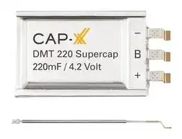
DMT3N4R2U224M3DTA0
Supercapacitor, Prismatic Ultra Thin, 0.22 F, 4.2 V, Solder, ± 20%
⚠️ Reference pricing provided. In case of supply shortages, we will connect you with our trusted procurement partners to ensure your project's continuity.
- Manufacturer: CAP-XX
- Product type: EDLC - Electric Double Layer Capacitors
- ESR: 0.3ohm
- SVHC: No SVHC (21-Jan-2025)
- Capacitance: 0.22F
- Voltage(DC): 4.2V
- Lead Spacing: -
- Product Range: DMT Series
- Product Width: 14mm
- Qualification: -
- Product Height: 2.2mm
- Product Length: 21mm
- Product Diameter: -
- Capacitor Mounting: Surface Mount
- Capacitor Terminals: Solder
- Capacitance Tolerance: ± 20%
- Lifetime @ Temperature: -
- Capacitor Case / Package: SMD
- Operating Temperature Max: 85°C
- Operating Temperature Min: -40°C
| Delivery and price | |
|---|---|
| Units per pack | 1000 |
| Price | 3.44 € |
| Current stock | 500+ |
| Lead time | 30 days |
Datasheet

## **DATASHEET** ## **DMT3N4R2U224M3DTA0 4.2V, 220mF, 300m** **, -40** **C to +85** **C** Revision 3.0, March 2025 ## **Electrical Specifications** **Table 1: Absolute Maximum Ratings** |**Parameter**|**Name**|**Conditions**|**Min**|**Typical**|**Max**|**Units**| |---|---|---|---|---|---|---| |**Terminal Voltage**|Vpeak||||4.2|V| |**Temperature**|Tmax||-40||+85|°C| **Table 2: Electrical Characteristics** |**Parameter**|**Name**|**Conditions**|**Min**|**Typical**|**Max**|**Units**| |---|---|---|---|---|---|---| |**Terminal Voltage**|Vn||0||4.2|V| |**Capacitance**|C|DC, 23°C|176|220|264|mF| |**ESR**|ESR|AC, 1kHz||300|360|m| |**Leakage Current**|IL|4.2V, 23°C<br>120hrs||5|10|µA| |**RMS Current**|IRMS|25°C|||3.2|A| |**Peak Current1 **|IP|23°C|||10|A| 1Non-repetitive current, single pulse to discharge fully charged supercapacitor. © CAP-XX Pty Limited 2023 | Tel +61 2 9420 0690 | www.cap-xx.com Page **1** of **15** Revision 3.0, March 2025 **DMT3N4R2U224M3DTA0 DATASHEET** **Table 3: Mechanical specification** ||**Length (mm)**|**Width (mm)**|**Thickness “T” (mm) Weight (gm)**|**Thickness “T” (mm) Weight (gm)**| |---|---|---|---|---| |DMT3N4R2U224M3DTA0|21 ± 0.5mm|14 ± 0.5|2.2 (max. 2.5)|0.6| |DMT3N4R2U224M3DTA1<br>(with adhesive tape on underside)|21 ± 0.5mm|14 ± 0.5|2.4 (max. 2.7)|0.6| **==> picture [166 x 130] intentionally omitted <==** **----- Start of picture text -----**<br> |¢—_______—>|ro! 10 ± 1 !<br>Adhesive Tape (A1 option) a<br>1 |<br>1) do|<br>ee<br>| y e | 4.5 typ.<br>7 ± 1<br>3.6 typ.<br>0.2 max. (tape)<br>**----- End of picture text -----**<br> ## **Mechanical drawing for DMT3N4R2U224M3DTA0** ## **Landing Pad Dimensions** © CAP-XX Pty Limited 2025 | Tel +61 2 9420 0690 | www.cap-xx.com Page **2** of **15** Revision 3.0, March 2025 **DMT3N4R2U224M3DTA0 DATASHEET** CARE ## **Part Numbering** ~~COMODO dsoOweod~~ ① ② ③ ④ ⑤ ⑥ ⑦ ⑧ ⑨ ① Series **Code** ⑤ Nominal Capacitance **DMT** General Purpose Type First two are significant digits and the third expresses the ~~———~~ number of zeroes which follow the two numbers **Code Nominal Capacitance** ② External Dimensions (L x W x T) **224** 22x10[4] µF = 220mF **Code L (mm) W (mm) T (mm) 33** 21.0±0.5 14.0±0.5 3.5 (max 3.8) ⑥ Capacitance Tolerance **4N** 21.0±0.5 14.0±0.5 2.2 (max 2.5) **Code Tolerance M** ±20% ~~|} ———jr~~ ③ Rated Voltage **Code Rated Voltage** ⑦ External Terminal **4R2** DC 4.2V **Code Terminal Specification 3D** 3 Terminals (+/-/Balance) ~~es ———~~ ④ ESR **Code ESR @ 1kHz** ⑧ Packaging **S** 130mΩ **Code Package Specification U** 300mΩ **T** Tray type, 50pcs/Tray ~~— —~~ ## ⑨ Inhouse Specification Code Expressed by two-digit alphanumerics ## **Printing** Capacitance Series Code + LW Size Code Negative Terminal Balance Terminal Positive Terminal Rated Voltage Manufacturer (CAP-XX or MURATA) Batch ID © CAP-XX Pty Limited 2025 | Tel +61 2 9420 0690 | www.cap-xx.com Page **3** of **15** Revision 3.0, March 2025 **DMT3N4R2U224M3DTA0 DATASHEET** ## **Batch ID** ① ② ③ ## ① Year **==> picture [180 x 498] intentionally omitted <==** **----- Start of picture text -----**<br> ||| |---|---| |Code|Year| |9|2019| |A|2020| |B|2021| |C|2022| |D|2023| |:|:| |Y|2044| |Z|2045| |==| |②|Month| |Code|Month| |F|January| |G|February| |H|March| |J|April| |K|May| |L|June| |M|July| |N|August| |P|September| |Q|October| |R|November| |S|December| |==| **----- End of picture text -----**<br> ## ② Month ## ③ 3-digit Unique ID The following code is used to identify the batch within the month © CAP-XX Pty Limited 2025 | Tel +61 2 9420 0690 | www.cap-xx.com Page **4** of **15** Revision 3.0, March 2025 **DMT3N4R2U224M3DTA0 DATASHEET** ## **Definition of Terms** In its simplest form, the Equivalent Series Resistance (ESR) of a capacitor is the real part of the complex impedance. In the time domain, it can be found by applying a step discharge current to a charged cell as in Fig. 1. In this figure, the supercapacitor is pre-charged and then discharged with a current pulse, I =1A for duration 0.01 sec. **==> picture [373 x 22] intentionally omitted <==** **----- Start of picture text -----**<br> Fig 1: Effective capacitance, instantaneous capacitance and ESR for an<br>DMT3N4R2U224M3DTA0<br>**----- End of picture text -----**<br> The ESR is found by dividing the instantaneous voltage step (∆V) by I. In this example = (4.194V3.921V)/1A = 273mΩ. The instantaneous capacitance (Ci) can be found by taking the inverse of the derivative of the voltage, and multiplying it by I. The effective capacitance for a pulse of duration tn, Ce(tn) is found by dividing the total charge removed from the capacitor (∆Qn) by the voltage lost by the capacitor (∆Vn). For constant current Ce(tn) = I x tn/Vn. Ce increases as the pulse width increases and tends to the DC capacitance value as the pulse width becomes very long (~10 secs). After 2msecs, Fig 1 shows the voltage drop V2ms = (3.921 V – 3.811V) = 110mV. Therefore Ce(2ms) = 1A x 2ms/110mV = 18.2mF. After 10ms, the voltage drop = 3.921 V – 3.711V = 210mV. Therefore Ce(10ms) = 1 A x 10ms/210mV = 47.6mF. The DC capacitance of a DMT3N4R2U224M3DTA0 = 0.22 F. Note that ∆V, or I*R drop, is not included because very little charge is removed from the capacitor during this time. Ce shows the time response of the capacitor and it is useful for predicting circuit behaviour in pulsed applications. © CAP-XX Pty Limited 2025 | Tel +61 2 9420 0690 | www.cap-xx.com Page **5** of **15** Revision 3.0, March 2025 ## **DMT3N4R2U224M3DTA0 DATASHEET** ## **Measurement of DC Capacitance** **Fig 2: Measurement of DC Capacitance for a DMT3N4R2U224M3DTA0** Fig 2 shows the measurement of DC capacitance by drawing a constant 100mA current from a fully charged supercapacitor and measuring the time taken to discharge from 80% to 40% of Vrated. In this case, C = 0.1A x 3.8s /(3.36-1.68)V = 226mF, which is well within the 220mF +/- 20% tolerance for a DMT3N4R2U224M3DTA0 cell. ## **Measurement of ESR** **Fig 3: Measurement of ESR for a DMT3N4R2U224M3DTA0** Fig 3 shows DC measurement of ESR by applying a step load current to the supercapacitor and measuring the resulting voltage drop. CAP-XX waits for a delay of 50µs after the step current is applied to ensure the voltage and current have settled. In this case the ESR is measured as 225mV/1A = 225mΩ. © CAP-XX Pty Limited 2025 | Tel +61 2 9420 0690 | www.cap-xx.com Page **6** of **15** Revision 3.0, March 2025 ## **DMT3N4R2U224M3DTA0 DATASHEET** ## **Effective Capacitance** **Fig 4: Effective Capacitance** Fig 4 shows the effective capacitance for the DMT3N4R2U224M3DTA0 @ 23°C. This shows that for a 1msec PW, you will measure 9% of DC capacitance or 20mF. At 10msecs you will measure 25% of the DC capacitance, and at 100msecs you will measure 69% of DC capacitance. Ceffective is a time domain representation of the supercapacitor's frequency response. If, for example, you were calculating the voltage drop if the supercapacitor was supporting 1A for 10msecs, then you would use the Ceff(10msecs) = 25% of DC capacitance = 55mF for a DMT3N4R2U224M3DTA0 , so Vdrop = 1A x ESR + 1A x duration/C = 1A x 300mΩ + 1A x 10ms / 55mF = 482mV. ## **Pulse Response** Fig 5 shows that the DMT3N4R2U224M3DTA0 supercapacitor does an excellent job supporting a GPRS class 10 pulse train, drawing 1.8A for 1.1ms at 25% duty cycle. The source is current limited to 0.6A and the supercapacitor provides the 1.2A difference to achieve the peak current. At first glance the freq response of Fig 8 indicates the supercapacitor would not support a 1ms pulse, but the Ceff of 20mF coupled with the low ESR supports this pulse train with only ~410mV droop in the supply rail. **Fig 5: DMT3N4R2U224M3DTA0 Pulse Response with GPRS Class 10 Pulse Train** © CAP-XX Pty Limited 2025 | Tel +61 2 9420 0690 | www.cap-xx.com Page **7** of **15** Revision 3.0, March 2025 ## **DMT3N4R2U224M3DTA0 DATASHEET** ## **DC Capacitance variation with temperature** **Fig 6: Capacitance change with temperature** Fig 6 shows that DC capacitance is approximately constant with temperature to 0C and then at -40C reduces to ~80% of DC capacitance at room temperature. ## **ESR variation with temperature** **Fig 7: ESR change with temperature** Fig 7 shows that ESR at -40°C is ~7.5 x ESR at room temp, and that ESR at 70ºC is ~0.5 x ESR at room temperature. © CAP-XX Pty Limited 2025 | Tel +61 2 9420 0690 | www.cap-xx.com Page **8** of **15** Revision 3.0, March 2025 ## **DMT3N4R2U224M3DTA0 DATASHEET** ## **Frequency Response** **Fig 8: Frequency Response of Impedance (biased at 4.2V with a 50mV test signal)** **Fig 9: Frequency Response of ESR, Capacitance & Inductance** Fig 8 shows the supercapacitor behaves as an ideal capacitor until approx. 1.25 Hz when the magnitude no longer rolls off proportionally to 1/freq and the phase crosses -45°. Performance of supercapacitors with frequency is complex and the best predictor of performance is Fig 4 showing effective capacitance as a function of pulse width. © CAP-XX Pty Limited 2025 | Tel +61 2 9420 0690 | www.cap-xx.com Page **9** of **15** Revision 3.0, March 2025 **DMT3N4R2U224M3DTA0 DATASHEET** ## **Leakage Current** **Fig 10: Leakage Current** Fig 10 shows the leakage current for DMT at room temperature. The leakage current decays over time, and the equilibrium value leakage current will be reached after ~120hrs at room temperature. The typical equilibrium leakage current is 2µA at room temperature. ## **Charge Current** **Fig 11: Charging a single cell of DMT3N4R2U224M3DTA0 (single cell: 440mF) with low current** The corollary to the slow decay in leakage currents shown in Fig 10 is that charging a supercapacitor at very low currents takes longer than theory predicts. At higher charge currents, the charge rate is as theory predicts. For example, it should take 0.44F x 2.1V / 0.00002A = 12.8hrs to charge a 0.44 F supercapacitor to 2.1V at 20µA, but Fig 11 shows it took 19hrs. At 100µA charging occurs at a rate close to the theoretical rate. © CAP-XX Pty Limited 2025 | Tel +61 2 9420 0690 | www.cap-xx.com Page **10** of **15** Revision 3.0, March 2025 ## **DMT3N4R2U224M3DTA0 DATASHEET** ## **RMS Current** ## **Fig 12: Temperature rise in DMT3N4R2U224M3DTA0 with RMS current** Continuous current flow into/out of the supercapacitor will cause self-heating, which limits the maximum continuous current the supercapacitor can handle. This is measured by a current square wave with 50% duty cycle, charging the supercapacitor to rated voltage at a constant current, then discharging the supercapacitor to half rated voltage at the same constant current value. For a square wave with 50% duty cycle, the RMS current is the same as the current amplitude. Fig 12 shows the increase in temperature as a function of RMS current. From this, the maximum RMS current in an application can be calculated, for example, if the ambient temperature is 40C, and the maximum desired temperature for the supercapacitor is 85C, then the maximum RMS current should be limited to 2.6A, which causes a 45C temperature increase. © CAP-XX Pty Limited 2025 | Tel +61 2 9420 0690 | www.cap-xx.com Page **11** of **15** Revision 3.0, March 2025 **DMT3N4R2U224M3DTA0 DATASHEET** ## **Packaging** ## **DMT3N4R2U224M3DTA0** **==> picture [375 x 231] intentionally omitted <==** **----- Start of picture text -----**<br> Minimum Packaging Quantity (500pcs)<br>Cover Tray<br>Outer Package<br>Sealed plastic bag<br>Oh Oh oh Oh oD<br>oh Oh Oh Oh OD<br>BdOh GdOh bdOh Gadoh OD& 10 Trays<br>Gd God Gd Gd &<br>Oh Oh Oh Oh OD Total 500pcs<br>Gd God God Gd &<br>oh Oh Oh Oh OD<br>Weight of 500 piece<br>package (parts + trays<br>500pcs 500pcs + plastic bag) = 573gms<br> abel abel ZY<br> abel<br> inimum shipping uantity 500pcs<br>120 mm<br>**----- End of picture text -----**<br> **==> picture [36 x 8] intentionally omitted <==** **----- Start of picture text -----**<br> 320 mm<br>**----- End of picture text -----**<br> CAP-XX uses sustainable packaging. All our packaging material are recyclable. The clear product trays are made from Polystyrene. ESD safe bubble wraps and bags are made from LDPE. The shipping boxes are corrugated cardboard. Please ensure all packaging is disposed in accordance with the relevant recycling procedures of the region where CAP-XX products are used. © CAP-XX Pty Limited 2025 | Tel +61 2 9420 0690 | www.cap-xx.com Page **12** of **15** Revision 3.0, March 2025 **DMT3N4R2U224M3DTA0 DATASHEET** ## **Storage** CAP-XX recommends storing supercapacitors in their original packaging in an air-conditioned room (≤ 25 °C) and < 50% relative humidity. Storage at continuous high temperature and humidity is not recommended and will cause premature ageing. Do not store supercapacitors in the following environments: - High temperature / high humidity - Direct sunlight - In direct contact with water, salt, oil or other chemicals - In direct contact with corrosive materials, acids, alkalis or toxic gases - Dusty environment - In environments subjected to shock and vibration ## **Shelf Life** Supercapacitors have a shelf life of minimum 2 years when stored uncharged at recommended storage conditions. ## **Cautions before use** CAP-XX supercapacitors are “burned in” during production, and have a defined polarity, as shown by the positive terminal marked on the face of the product. Reversing the polarity of the device will not damage the device but may cause a rise in the ESR and will void the warranty. Please verify the orientation of the supercapacitor in accordance with the product markings before assembly. CAP-XX supercapacitors are heat-sensitive. Over-heating of the supercapacitor may result in a degradation of performance and useful life. CAP-XX supercapacitors must only be used within their rated voltage range. Over-voltage may cause swelling and eventually, product failure. CAP-XX supercapacitors are fully discharged when shipped. Devices should be handled and soldered in a discharged state. ## **Soldering and Assembling** CAP-XX supercapacitors are designed for direct soldering onto the PCB. Soldering the terminals to the PCB will ensure the highest contact reliability and lowest contact resistance. Do NOT solder directly to the device casing. This will cause permanent internal damage to the supercapacitor. CAP-XX supercapacitors are NOT SUITABLE for infrared reflow soldering, hot-air reflow soldering, or wave soldering. They should be mounted as a secondary operation, using a manual soldering iron, a hot bar soldering jig, conductive adhesive, ultrasonic welding or laser welding. CAP-XX recommends the use of a water-soluble flux, or a no-clean (low residue) flux, and low temperature solder compounds. Please solder under the following conditions: - Solder Type: Resin flux cored solder wire (ø1.2mm) - Solder: Lead-free solder: Sn-3Ag-0.5Cu - Soldering iron temperature at 350°C±10°C - Solder iron wattage: 70W or less - Soldering time: 3 to 4sec. - The same terminal should be soldered 3 or less times. © CAP-XX Pty Limited 2025 | Tel +61 2 9420 0690 | www.cap-xx.com Page **13** of **15** Revision 3.0, March 2025 ## **DMT3N4R2U224M3DTA0 DATASHEET** If a hot-air gun is used to reflow the solder during a re-mount or de-mount, care must be taken to prevent excessive heating of the package adjacent to the solder terminals. Allow at least 15 sec between successive soldering attempts for the device to cool down. Please consult CAP-XX if you wish to wash the device after soldering. © CAP-XX Pty Limited 2025 | Tel +61 2 9420 0690 | www.cap-xx.com Page **14** of **15** Revision 3.0, March 2025 **DMT3N4R2U224M3DTA0 DATASHEET** ## **Vibration and Shock Testing** ## **Shock** CAP-XX has undertaken tests in accordance with IEC68-2-27 to determine the effects of repeated shocks on both the mechanical integrity and electrical performance of its supercapacitors: - Type: Half-Sine - • Amplitude: 30G • Duration: 18ms • No. of cycles: 3 in each direction (18 in total) • No. of axes: 3, orthogonal Results: final C ≥ 80% of initial, final ESR ≤ 120% of initial, the final thickness is within specification. _Note that this test was undertaken on the standard product with adhesive mounting tape (Nitto No.5000NS). To achieve the highest levels of resistance to shock, CAP-XX recommends the use of an adhesive mounting tape on the underside of the device._ ## **Vibration** CAP-XX has undertaken tests to determine the effects of sustained vibration on both the mechanical integrity and electrical performance of its supercapacitors. The test standard is in accordance with IEC60065-2-6. - Type: Sinusoidal - • Frequency: 10 - 500Hz - Amplitude: 0.75 mm or acceleration: 100 m/s[2] (whichever is less stringent) - Sweep Rate: 1 min/octave - No. of cycles: 10 (10Hz - 500Hz - 10Hz) - • No. of axes: 3, orthogonal - Total test time: 6 hours Results: final C ≥ 80% of initial, final ESR ≤ 120% of initial, the final thickness is within specification. _Note that this test was undertaken on the standard product with adhesive mounting tape (Nitto No.5000NS). To achieve the highest levels of resistance to shock, CAP-XX recommends the use of an adhesive mounting tape on the underside of the device._ ## **Drop Test** CAP-XX has undertaken tests to determine the effects of repeated drops on both the mechanical integrity and electrical performance of its supercapacitors: Supercapacitor is discharged - Mount product to 150g box with adhesive mounting tape (Nitto No.5000NS) - Drop the box from 0.25m / 0.5m / 1.0m / 1.5m - Repeat 3 times for 6 sides (18 in total) Results: No electrical or mechanical degradation observed. © CAP-XX Pty Limited 2025 | Tel +61 2 9420 0690 | www.cap-xx.com Page **15** of **15**
Updated at April 29, 2026
About Novapart
Novapart is a B2B electronic component broker specialising in stock shortages and cost reduction. We source hard-to-find parts and identify compliant alternatives across a catalogue of 410,000+ components from 500+ manufacturers.
Learn more →Stock Shortage Specialist
When a component is unavailable, discontinued or has an unacceptable lead time, we tap into our network of vetted European and Asian distributors to source what you need — without compromising on quality or traceability.
Request a quote →Compliant Alternatives
We identify pin-to-pin, electrically equivalent substitutes that meet the same certifications (RoHS, AEC-Q100, REACH) as your original specification — validated against datasheets, not just part numbers. Often at a lower cost.
BOM Analysis service →