


DMS01-VM1-RS12-C
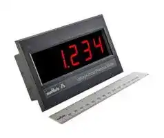
DIGITAL PANEL METER, DC VOLT, 11-13VDC
- Manufacturer: MURATA
- Product type: Digital Panel Meters
- Available until stocks are exhausted
- SVHC: No SVHC (27-Jun-2024)
- Meter Range: -200mV to +200mV, -2V to +2V
- Digit Height: 25.4mm
- Product Range: DMS01-VM1 Series
- Meter Function: DC Voltage
- Panel Cutout Width: 139.07mm
- Supply Voltage Max: 13VDC
- Supply Voltage Min: 11VDC
- Panel Cutout Height: 59.69mm
- No. of Digits / Alpha: 3.5
- Operating Temperature Max: 50°C
- Operating Temperature Min: 0°C
| Delivery and price | |
|---|---|
| Units per pack | 1 |
| Price | 88.74 € |
| Current stock | 10+ |
| Lead time | 30 days |
**DMS01-VM1 Series** ## Murata Power Solutions ## Large Format Digital DC Voltmeter ## **PRODUCT OVERVIEW** DMS01-VM1-RS12-C is a robust, configurable, digital panel meter that provides precise measurement and display of DC voltage on a highly visible red 1” (25mm) tall, 3½ digit sevensegment LED display with adjustable brightness. DIP switches are provided for selectable input voltage range, decimal point placement; Independent trim-potentiometers provide additional precision optimization for specialized applications. An external 12VDC power source provides power to the meter and the internal DC-DC converter accommodates a +/-48V common-mode measurement range with respect to the power supply input, simplifying a wide range of measurement applications. The internal digital filter enhances performance in electrically noisy environments. This digital panel meter is ideal for laboratory instrumentation, factory automation, and any application that requiring precise voltage monitoring. ## **Features** - Measures DC Volts with user selectable ±2 VDC or ±200 mVDC ranges - ~~HT~~ Bright 1” red LED display, readable ~ - ~~S~~ at distance of 80 feet ( 24 m) Wide common-mode input range (±48V) - Digital filter for optimizing ~~a~~ measurements in electrically noisy environments ORDERING INFORMATION DMS01-VM1-RS12-C Digital Voltmeter, 1” Red Display, 12VDC Power **==> picture [111 x 8] intentionally omitted <==** **----- Start of picture text -----**<br> SIMPLIFIED BLOCK DIAGRAM<br>**----- End of picture text -----**<br> - Operates from an external 12VDC power supply - Mounts with adhesive strips (supplied) or screws ~~oo~~ - 0.2% typical accuracy Adjustable display brightness **==> picture [99 x 18] intentionally omitted <==** **----- Start of picture text -----**<br> For full details go to<br>www.murata-ps.com/rohs<br>**----- End of picture text -----**<br> **www.murata-ps.com/support** DMS01-VM1.A01.D07 Page 1 of 6 **DMS01-VM1 Series** Large Format Digital DC Voltmeter ## Murata Power Solutions |DC ELECTRICAL CHARACTERISTICS(Typical @ 25C,+12VDC supplyunless otherwise noted)<br>~~CO~~|DC ELECTRICAL CHARACTERISTICS(Typical @ 25C,+12VDC supplyunless otherwise noted)<br>~~CO~~|DC ELECTRICAL CHARACTERISTICS(Typical @ 25C,+12VDC supplyunless otherwise noted)<br>~~CO~~|DC ELECTRICAL CHARACTERISTICS(Typical @ 25C,+12VDC supplyunless otherwise noted)<br>~~CO~~|DC ELECTRICAL CHARACTERISTICS(Typical @ 25C,+12VDC supplyunless otherwise noted)<br>~~CO~~| |---|---|---|---|---| |**Parameter**<br>~~CO~~|**Min**<br>~~CO~~|**Typ**<br>~~CO~~|**Max**<br>~~CO~~|**Units**<br>~~CO~~| |Supply Voltage (Operating)|+11|+12|+13|V| |Absolute Maximum Supply Voltage|-1||+14|V| |Supply Current1(Operating at maximum intensity)|||100|mA| |(Operating at maximum intensity)|||60|mA| |Digits|3.5|||| |Digit Height|1 (25.4)|||inch (mm)| |Display Update Rate|2.5|||Sa/s| |Decimal Selection|Manual/Auto|||| |Display Color|Red (627nm pk)|||| |Over-range Indication|Flashing Display|||| |Measurement range (200mV range)|-200||+200|mV| |(2V range)|-2||+2|V| |Accuracy||0.2%|1%|| |Zero-Offset (200mV range)|-2||+2|count| |(2V range)|-2||+2|count| |Input Impedance||5G||Ω| |Offset Trim Range||±2||% full-scale| |Scale Trim Range||±1||%| |Temperature Drift (0 to +50˚C)||±0.01||count/°C| |Absolute Maximum Input Voltage (+VIN to-VIN)|-30||+30|V| |Common-mode Input Range (-VIN)–(-VS)|-48||+48|V| 1 based on a display value of “1.888” |PHYSICAL/ENVIRONMENTAL<br>~~|~~|PHYSICAL/ENVIRONMENTAL<br>~~|~~|PHYSICAL/ENVIRONMENTAL<br>~~|~~|PHYSICAL/ENVIRONMENTAL<br>~~|~~|PHYSICAL/ENVIRONMENTAL<br>~~|~~|PHYSICAL/ENVIRONMENTAL<br>~~|~~|PHYSICAL/ENVIRONMENTAL<br>~~|~~| |---|---|---|---|---|---|---| |**Parameter**|**Min**||**Typ**||**Max**|**Units**| |Operating Temperature|0||||+50|C| |Storage Temperature|-40||||+75|C| |Humidity (Non-condensing)|||||85|%RH| |Weight|||6.14 (174)|||oz (g)| |**User Controls**||||||| |Brightness|single-turn potentiometer|||||| |Offset and Gain Adjustment|QTY 2 12-turn trim potentiometers|||||| |Dipswitch configuration setting for:<br>-<br>Input voltage range<br>-<br>Digital filter enable<br>-<br>Decimal point placement<br>-<br>Scale and offset enable|“S1” 6-position|||||| |Overall Dimensions|5.86 (149) L x 3.36 (86) W x 1.43 (37) H|||||inch (mm)| |**Terminal Blocks**|**Min**|**Typ**||**Max**||**Units**| |Wire Size|24|||14||AWG| |Insulation Strip Length||0.25 (6)||||inch (mm)| |Screw Tightening Torque||56.6 (0.4)||||oz-in (N-m)| ## ~~hieee~~ OPERATION **Measurement Type and Capabilities** - The DMS01-VM1 measures DC voltage with two user-selectable input ranges of ±50mV and ±100mV. - Measurements are displayed with 3-1/2 digits of resolution. - A high-impedance input helps maintain accuracy with a variety of signal sources. - The meter’s measurement terminals are electrically isolated from the power terminals through a DC-DC converter, providing a high common-mode input range (+/-48V) for the input (relative to the power terminals), simplifying a wide range of measurement applications. - Meter requires external 12VDC power (not included). **www.murata-ps.com/support** DMS01-VM1.A01.D07 Page 2 of 6 **DMS01-VM1 Series** Large Format Digital DC Voltmeter ## Murata Power Solutionss REAR PANEL LAYOUT: SCREW TERMINAL CONNECTIONS & CONTROLS |**Offset Adjust**|**Offset Adjust**|**Offset Adjust**|**Offset Adjust**|||||||||||| |---|---|---|---|---|---|---|---|---|---|---|---|---|---|---| |**Scale Adjust**||||||||||||||| |**Brightness Adjust**||||||||||||||| |||||||||||||||| |||||||||||||||Terminal Block| |||||||||||||**Terminal #**|**Name**|**Function**| |**1**<br>**2**<br>**3**<br>**4**<br>**5**<br>**6**<br>**S1**<br>waded|||**1**<br>**2**<br>**3**<br>**4**<br>**Terminal Block**<br>®@@®B|||||||||1<br>2<br>3<br>4|-VS<br>+VS<br>-IN<br>+IN|Power Supply Terminals (+12VDC)<br>Measurement Input Terminals| **Brightness Adjust** – This single-turn potentiometer supports adjustment of the meter’s LED display brightness for maximum readability. Turning the pot clockwise increases brightness, while turning it counterclockwise decreases brightness. **Offset Adjust** – This 12-turn potentiometer supports the adjustment of meter offset. In the vast majority of applications, this function is not needed as the meter’s offset is precisely adjusted to zero at factory calibration. Turning the pot clockwise will give a negative offset, while turning it counterclockwise give a positive offset. **Scale Adjust** – This 12-turn potentiometer supports the adjustment of the meter’s scale. In the vast majority of applications, this function is not needed as the meter’s scale is precisely adjusted at factory calibration. Turning the pot clockwise decreases the gain, while turning it counterclockwise increases the gain. **S1** – 6-position dipswitch used to configure the meter’s various options. See Meter Configuration below for details. ## CONNECTION EXAMPLE In this example, the load connects to terminals 3 and 4, where terminal 3 is the negative input terminal (-IN) and terminal 4 is the positive input terminal (+IN). The 12V power supply connects to terminals 1 and 2, where terminal 1 is the negative power supply terminal (-VS) and terminal 2 is the positive power supply terminal (+VS). **www.murata-ps.com/support** DMS01-VM1.A01.D07 Page 3 of 6 **DMS01-VM1 Series** Large Format Digital DC Voltmeter ## Murata Power Solutions ~~|~~ METER CONFIGURATION The DMS01-VM1 family is configured through dipswitch S1 on the back of the meter. Each switch on dipswitch S1 is identified by SW#. For example, SW1 is switch 1 on S1, which controls the input range. The following features may be controlled: Input Range Selection |METER CONFIGURATION<br>~~|~~|METER CONFIGURATION<br>~~|~~|METER CONFIGURATION<br>~~|~~|METER CONFIGURATION<br>~~|~~|METER CONFIGURATION<br>~~|~~|METER CONFIGURATION<br>~~|~~| |---|---|---|---|---|---| |The DMS01-VM1 family is configured through dipswitch S1 on the back of the meter. Each switch on dipswitch S1 is identified by SW#. For<br>example, SW1 is switch 1 on S1, which controls the input range. The following features may be controlled:<br>~~|~~|||||| |Input Range Selectionput Range Selectionut Range Selectionge Selectione Selection|||||| |**Input Range Setting**||**SW1**||**Dipswitch**|**Description**| |+/-200mV||OFF||**ON**<br>**1**<br>**2 3 4 5 6**|SW1 controls the meter’s input range. In the OFF position the<br>input range is +/-200mV, while in the ON position the meter’s<br>range is +/-2V.| |+/-2V||ON||**ON**<br>**1**<br>**2 3 4 5 6**|| |Digital Filter|||||| |**Digital Filter On/Off**||**SW2**||**Dipswitch**|**Description**| |OFF||OFF||**ON**<br>**1**<br>**2 3 4 5 6**<br>U~~B~~UUUU|SW2 controls the meter’s digital filter. In the OFF position, the<br>filter is disabled and readings are updated at maximum speed. In<br>the ON position, the filter is enabled, and readings are processed<br>through a moving average filter, which results in more stable<br>readings, but a slower response.| |ON||ON||**ON**<br>**1**<br>**2 3 4 5 6**<br>U~~B~~UUUU|| |Scale and Offset Adjust|||||| |**Trim Enable On/Off**||**SW6**||**Dipswitch**|**Description**| |OFF||OFF||**ON**<br>**1**<br>**2 3 4 5 6**|Scale and Offset Adjust - The DMS01 voltmeter has 2<br>potentiometers for adjustment of the measurement scale and<br>offset controls which can be enabled by SW6. When the switch is<br>turned to the off position the trim is disabled. When the switch is<br>turned to the on position the trim is enabled.| |ON||ON||**ON**<br>**1**<br>**2 3 4 5 6**|| |Decimal Point Selection|||||| |**Decimal**<br>**Placement**|**SW3**|**SW4**|**SW5**|**Dipswitch S1**|**Description**| |0000|OFF|OFF|OFF|**ON**<br>**1**<br>**2 3 4 5 6**<br>|J~~HHH~~|Decimal Point Placement – SW3 through SW5 control the decimal<br>point placement options as shown in the table below. Setting all<br>of the switches to ON enables AUTO mode, which sets the<br>decimal point based on the input range select (SW1): 000.0 for<br>200mV range and 0.000 for 2V range. Setting only one of the<br>switches on at a time allows the user to choose the decimal place<br>they want.| |0.000|ON|OFF|OFF|**ON**<br>**1**<br>**2 3 4 5 6**<br>| ~~/BBH~~||| |00.00|OFF|ON|OFF|**ON**<br>**1**<br>**2 3 4 5 6**<br>JU~~BAG~~||| |000.0|OFF|OFF|ON|**ON**<br>**1**<br>**2 3 4 5 6**<br>| ~~JHB~~|| |AUTO|ON|ON|ON|**ON**<br>**1**<br>**2 3 4 5 6**<br>| ~~BBB~~|| **www.murata-ps.com/support** DMS01-VM1.A01.D07 Page 4 of 6 **DMS01-VM1 Series** Large Format Digital DC Voltmeter ## Murata Power Solutionss ## TECHNICAL NOTES ## **1. Calibration** The DMS01-VM1 is calibrated at the factory at the time of manufacture. When the Trim Enable switch (SW6) is turned off, the unit ignores the scale and offset potentiometer settings and reverts to factory calibration. When the Trim Enable switch is turned ON, the unit’s effective calibration may be changed by the user and may no longer be within datasheet specifications. ## **2. Protection and Fusing** The DMS01-VM1 contains an internal PTC fuse as well as other protective elements that are intended for protection against brief electrical transients and misconnect conditions. Additional external protective components such as fuses and transient suppressors may be required depending on the application in which the meter is deployed. ## **3. Noisy Power Supplies** In systems with noisy power supplies, connecting an external, non-polarized capacitor across the +VS and -VS inputs can help reduce measurement errors. In certain situations, the use of twisted pair or shield wiring may be required. ## **4. Installation** IMPORTANT! To ensure safe and reliable operation, DMS01 meters must be installed and serviced by qualified technical personnel. Contact Murata Power Solutions if there is any doubt regarding their installation or operation. ## **5. Over-Range Limit** The meter will flash on and off when the input pf the meter exceeds its minimum or maximum input voltage/current. ## PANEL INSTALLATION Panel Cutout Note: When mounting panel meter with hardware, a four hole pattern (four outermost holes) or the six hole pattern may be used at the customer’s option. **www.murata-ps.com/support** DMS01-VM1.A01.D07 Page 5 of 6 **DMS01-VM1 Series** Large Format Digital DC Voltmeter ## Murata Power Solutionsse ## MECHANICAL SPECIFICATIONS Murata Power Solutions, Inc. 129 Flanders Rd. Westborough, Ma 01581, USA. ISO 9001 and 14001 REGISTERED **This product is subject to the following operating requirements and the Life and Safety Critical Application Sales Policy: Refer to: http://www.murata-ps.com/requirements/** Murata Power Solutions, Inc. makes no representation that the use of its products in the circuits described herein, or the use of other technical information contained herein, will not infringe upon existing or future patent rights. The descriptions contained herein do not imply the granting of licenses to make, use, or sell equipment constructed in accordance therewith. Specifications are subject to change without notice. _**©2019 Murata Power Solutions, Inc..**_ **www.murata-ps.com/support** DMS01-VM1.A01.D07 Page 6 of 6
Updated at June 9, 2026
Established in Kyoto in 1944, Murata has grown into a global leader in the design and manufacture of advanced electronic components, specializing in ceramic passive components, wireless connectivity modules, and power conversion technologies. Renowned for its foundational work in materials science and process innovation, Murata delivers solutions that drive the evolution of modern electronics across telecommunications, mobility, industrial, and healthcare applications. This extensive portfolio is anchored by a broad selection of high-performance passive components, heavily focused on inductive solutions. Engineers can choose from hundreds of specialized RF inductors and power inductors engineered for exceptional reliability, efficiency, and miniaturization. The range also features robust EMC and RFI suppression solutions, highlighted by industry-leading common mode chokes and power line filters designed to ensure signal integrity and strict regulatory compliance in demanding circuit environments. Beyond inductive and filtering components, the offering encompasses a comprehensive array of critical circuit protection, timing, and power devices. Murata's precision NTC and PTC thermistors provide essential temperature sensing and thermal management, while its robust lineup of ceramic resonators and quartz crystals ensures highly accurate frequency control. Supported by premium non-rechargeable batteries, polymer capacitors, and advanced sensing transducers, Murata equips designers with the versatile building blocks required for next-generation technological development.
About Novapart
Novapart is a B2B electronic component broker specialising in stock shortages and cost reduction. We source hard-to-find parts and identify compliant alternatives across a catalogue of 410,000+ components from 500+ manufacturers.
Learn more →Stock Shortage Specialist
When a component is unavailable, discontinued or has an unacceptable lead time, we tap into our network of vetted European and Asian distributors to source what you need — without compromising on quality or traceability.
Request a quote →Compliant Alternatives
We identify pin-to-pin, electrically equivalent substitutes that meet the same certifications (RoHS, AEC-Q100, REACH) as your original specification — validated against datasheets, not just part numbers. Often at a lower cost.
BOM Analysis service →