
Image not available
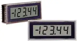
Illustrative purposes only

DMS-40LCD-1/2-5-C.
VOLTAGE METER
⚠️ Reference pricing provided. In case of supply shortages, we will connect you with our trusted procurement partners to ensure your project's continuity.
- Manufacturer: MURATA POWER SOLUTIONS
- Product type: Digital Panel Meters
- Meter Range: -2V to +2V / -20V to +20V
- Digit Height: 10.2mm
- Meter Function: DC Voltage
- Panel Cutout Width: 53.85mm
- Supply Voltage Max: 5.25V
- Supply Voltage Min: 4.75V
- Panel Cutout Height: 22.35mm
- No. of Digits / Alpha: 4-1/2
- Operating Temperature Max: 50°C
- Operating Temperature Min: 0°C
| Delivery and price | |
|---|---|
| Units per pack | 100 |
| Price | 66.36 € |
| Current stock | 10+ |
| Lead time | 30 days |
Datasheet

## **www.murata-ps.com**

## **- DMS 40LCD Series**

4½ Digit, LCD Display Digital Panel Voltmeters

## **FEATURES**

- Scientifi c-grade accuracy, ±2  counts

- Low power, typically 12.5mW

- Miniature size:

- 2.17" x 0.92" x 0.43" (55mm x 23mm x 11mm)

- Large (0.4”/10.2mm), enhanced-contrast, LCD display

- Backlit displays optional

- Epoxy-encapsulated, 12-pin DIP

- Panel or pc-board mountable

- 3 differential, dual, input voltage ranges

- Single +5V supply or 9V battery

- User-selectable decimal point placement

- Low-battery "BAT" annunciator

- 0 to +50°C temperature range

- Low Cost

Offering a unique combination of low cost, scientifi c-grade accuracy (±2 counts), component-like convenience and outstanding reliability, DMS-40LCD Series 4½ Digit DPM’s provide the ultimate combination of price, precision and convenience. These miniature (2.17˝ x 0.92˝ x 0.43˝) digital voltmeters combine  an advanced, autozeroing A/D converter, a precision reference circuit and a large (0.4˝/10.2mm high), easy-to-read LCD display in a single, fully encapsulated, 12-pin DIP package. All models incorporate a built-in bezel and are easily mounted in either panels or pc boards.

Each DMS-40LCD meter has a dual-range, differential, input confi guration (±200mV/±2V, ±2V/±20V or ±20V/±200V) and is available with a backlit or non-backlit display. Input impedance is a minimum 800kΩ, and CMRR is typically 86dB (dc to 60Hz). CMV is ±2V, and all models are overvoltage protected to ±250V (on their non-inverting inputs).

All DMS-40LCD meters are fully functional and operate from a single +5V supply (drawing 3.5mA max.) or a single 9V supply/battery (drawing 2.5mA max.). All models feature autopolarity changeover and overrange indication. A display HOLD function is standard on all non-backlit models.

Thanks to their rugged epoxy-based encapsulation and their advanced, factory-calibrated A/D converters, DMS-40LCD meters are able to withstand the harshest environments and never require adjustment or calibration. Plug-in convenience, long-term stability and wide operating temperature range (0 to +50°C) make DMS-40LCD meters the right solution for any high-accuracy DPM requirement.

## ~~|~~ **SIMPLIFIED SCHEMATIC DIAGRAM**

**==> picture [518 x 254] intentionally omitted <==**

**----- Start of picture text -----**<br>
+5V<br>+5V SUPPLY/ 1 V+ 12<br>(–) INPUT LO<br>+BATTERY<br>R2<br>–5V 0.01µF<br>RANGE 2 DC/DC R1 11<br>SELECT CONVERTER V– (+) INPUT HI<br>≈+2.2V<br>Cop<br>A/D 10 ANALOG<br>5V RETURN/ 3 CONVERTER COMMON<br>–BATTERY J 0 Vdc e J1 e |<br>DATA 1.23V<br>4 REF.<br>DP 3<br>BABATT<br>9 HOLD/<br>5 BACKLIGHT<br>DP 2<br>8<br>DP 4<br>6 +5V<br>DP 1<br>7 REFERENCE<br>IN/OUT<br>Lo |.<br>an R1 = 100k on ±200mV/±2V (-0/1) models and 909k on all other models. DC/DC converter is not used on 9V-powered models,<br>For full details go to R2 is not used on ±200mV/±2V (-0/1) models. J1 is connected.<br>www.murata-ps.com/rohs R2 = 101k on ±2V/±20V (-1/2) models and 9.2k on ±20V/±200V (-2/3) models. Hold function is not available on backlit models.<br>**----- End of picture text -----**<br>


**www.murata-ps.com/support**

**MPM_DMS40LCD.D01** Page 1 of 6

## **- DMS 40LCD Series**

4½ Digit, LCD Display Digital Panel Voltmeters

## **Performance/Functional Specifi cations**

Typical at TA = +25°C and supply voltage = +5V (using the single-ended input circuit) or +9V (using the differential input circuit), unless otherwise noted.

**==> picture [249 x 620] intentionally omitted <==**

**----- Start of picture text -----**<br>
Analog Inputs Min. Typ. Max. Units<br>Full Scale Input Range:  ➀<br>  DMS-40LCD-0/1 – ±200/±2 – mV/V<br>  DMS-40LCD-1/2 – ±2/±20 – V/V<br>  DMS-40LCD-2/3 – ±20/±200 – V/V<br>Input Impedence:<br>  DMS-40LCD-0/1 100 1000 MΩ<br>  DMS-40LCD-1/2 0.8 1 – MΩ<br>  DMS-40LCD-2/3 0.8 1 – MΩ<br>Overvoltage Protection   ➁ – – ±250 Volts<br>Common Mode Voltage Range  ➂ – – ±2 Volts<br>CMRR  (dc to 60Hz) – 86 – dB<br>Control Inputs  ➃<br>Decimal Pt. Placement  (Pins 4-6, 8):<br>  Functionality Tie to pin 3 to activate<br>  Logic Compatibility TTL (on 5V-powered models)<br>Hold/Backlight Functionally  (Pin 9)<br>  Backlit Models Tie to pin 1 to activate<br>  Non-backlit Models Tie to pin 3 to hold reading<br>Performance<br>Sampling Rate 2.5 reading per second<br>Accuracy (1 minute warm-up):<br>  DMS-40LCD-0/1 (Vin = +0.19/1.9V) – ±2 ±3 Counts<br>  DMS-40LCD-1/2 (Vin = +1.9V) – ±2 ±3 Counts<br>  DMS-40LCD-1/2 (Vin = +19V) – ±3 ±4 Counts<br>  DMS-40LCD-2/3 (Vin = +19/190V) – ±3 ±4 Counts<br>Zero Reading  (Vin = 0 Volts) “–001” “000” “001”<br>Temperature Drift  (0 = +50°C)<br>DMS-40LCD-0/1 – ±0.4 ±0.8 Cnts/°C<br> DMS-40LCD-1/2 – ±0.6 ±1 Cnts/°C<br>  DMS-40LCD-2/3 – ±0.6 ±1 Cnts/°C<br>Power Supply Requirements (5V Models)<br>Supply Voltage +4.75 +5.00 +5.25 Volts<br>Supply Current:<br>Standard Models – +2.5 +3.5 mA<br>Backlit Models – +37 +45 mA<br>Power Supply Requirements (9V Models)<br>Supply Voltage +7.5 +9.00 +14.0 Volts<br>Supply Current:<br>Standard Models – +1.5 +2.5 mA<br>Backlit Models – +37 +45 mA<br>Display<br>Display Type and Size 4½ digit, 0.4"/10.2mm high LCD<br>Polarity Indication Autopolarity ("–" for negative Vin)<br>Overrange Indication "–1____" for negative inputs<br>"1____" for positive inputs<br>**----- End of picture text -----**<br>


|**Physical/Environmental**|**Physical/Environmental**||||
|---|---|---|---|---|
|**Operating Temperature**|0|–|+50|°C|
|**Storage Temperature**|–20|–|+75|°C|
|**Humidity (non-condensing)**|0|–|95|%|
|**Case Material**||Polycarbonate|||
|**Weight**|0.75 ounces (21 grams)||||


➀  Each model in the DMS-40LCD Series offers two input voltage ranges  that are user-selectable via pin strapping. 5V-powered models can be used to perform either differential or single-ended measurements. 9V-powered models can only be used for differential measurements.

➁  Applies for transient or continuous overvoltages applied to (+) INPUT HI (pin 11) with (–) INPUT LO (pin 12) properly connected.  Pin 12 is not  overvoltage protected (see Figure 1). Voltages applied to pin 12 should not exceed the supply voltage.

➂  Listed spec applies to 5V-powered models only. For 9V-powered models, both (–) INPUT LO (pin 12) and (+) INPUT HIGH (pin 11) must always be at least 1.5V above –BATTERY (pin 3) and at least 1.5V below +BATTERY (pin 1).

➃  See Technical Notes.

## **Ordering Information**

## **DMS-40LCD - 0/1 - 5     -C**

Add -C for RoHS **Input Ranges: 0/1** = ±200mV/±2V Leave blank for standard **1/2** = ±2V/±20V **Power Source:** models. Add **B** for **2/3** = ±20V/±200V **5** = +5V backlit models. **9** = +9V

**See www.murata-ps.com/dpm-availability for model-specifi c availability.**

**Accessories: DMS-30-CP** Panel cutout punch **DMS-BZL1-C** DMS-40 bezel assembly **DMS-BZL2-C** DMS-40 bezel assembly with sealing gasket **DMS-EB-C** Application/evaluation board with standard MOLEX connector, decimal point solder pads and attenuation resistor pads.

A panel-mount retaining clip is supplied with each model.

## **TECHNICAL NOTES**

**1.   Input Voltage Range Selection:** Each model in the DMS-40LCD Series offers two, user-selectable, input voltage ranges as indicated in the Performance/Functional Specifi cations Table and the Ordering Information.  To select the higher range of any device (such as the ±2V range for the DMS-40LCD-0/1), connect pin 2 (RANGE SELECT) to pin 1 (+5V SUPPLY/+BATTERY).  To select the lower range, leave pin 2 open.

**2. Decimal Point Placement:** The location of the decimal point is userselectable, and the decimal point control pins (DP1-DP4) are active low functions.  Select the appropriate decimal point by tying the appropriate pin (pin 4, 5, 6 or 8) to pin 3 (5V RETURN/–BATTERY).  Unused decimal point location pins should be left open.  For 5V-powered models, the decimal location pins are TTL compatible and may be hard wired as described above or driven with 5V TTL logic gates.

**www.murata-ps.com/support**

**MPM_DMS40LCD.D01** Page 2 of 6

## **- DMS 40LCD Series**

4½ Digit, LCD Display Digital Panel Voltmeters

**3. Low Battery Annunciator:** The “BAT” annunciator in the upper left-hand corner of the display turns on when the supply voltage for 5V-powered models falls below the approximate range of 2.7V to 3.7V, or when the supply voltage for 9V-powered models falls below the approximate range of 5.4 to 7.2V. This function can not be disabled.

   - Please note, the “BAT” annunciator is a convenience feature only. The supply voltage ranges specifi ed previously in the ‘Performance/Functional Specifi cations’ section of this data sheet must be maintained at all times in order to ensure the DMS-40LCD meets its accuracy and stability specifi cations.

**4. HOLD/BACKLIGHT (Pin 9) Function:** For non-backlit models, connecting pin 9 (HOLD/BACKLIGHT) to pin 3 (5V RETURN/ –BATTERY) will hold  (continuously display) the last reading. If not used, pin 9 should be left open for these models.

For backlit models, grounding pin 9 (i.e. connecting it to pin 3) turns on the backlighting LED’s.  9V-powered backlit models function with supply voltages up to +14V, however, activating the backlight with voltages greater than 9.2V can damage the meter.  Therefore, a 1/4 Watt series resistor must be installed between pins 3 and 9 in these situations.  The value of the series resistor is determined using the following formula:

+BATTERY – 9.2V RSeries = Ohms 0.035

Example: If +BATTERY (pin 1 with respect to pin 3) is +12.6V,

+12.6 – 9.2V RSeries = Ohms 0.035 RSeries =  97 Ohms

In any backlit application, including those with supply voltages < 9.2V, the current drawn by the backlight (and therefore the current drawn by the meter) can be reduced by installing a 1/4 Watt resistor between pins 3 and 9. The brightness of the backlight will be reduced proportionately.

**5. ANALOG COMMON (Pin 10):** This pin is connected to an internal, low-noise, “relative” ground.  It is used in certain “fl oating” measurements as described in the Applications section of this data sheet and Ap Note DMS-AN3 at http://www.murata-ps.com/data/meters/dms-an3.pdf. **Pin 10 should not be connected to pin 3 (5V RETURN/–BATTERY) or to your system’s analog ground.**

**6. REFERENCE IN/OUT (Pin 7):** This pin accesses the meter’s internal reference and is used during the factory calibration procedure. Pin 7 should be left open in most common applications. It can be used in certain “ratiometric” applications in which it is desireable for the meter’s reference to track an external reference.

**7. Gain Adjust:** There is a gain-adjust potentiometer on the back of each meter.  It has approximately ±150 counts of adjustment range.  Since these devices essentially have no zero/offset errors, a gain adjustment is effectively an overall accuracy adjustment.  Though they may be performed at any point (except zero), accuracy adjustments are most effective when performed with higher level input signals.

**8. Soldering Methods:** All models in the DMS-40LCD Series easily withstand most common wave soldering operations.  We recommend, however, you evaluate the effects your particular soldering techniques may have on the meter’s plastic case and high-precision electrical performance.  We recommend the use of no-clean solders.

## **9. Suggested Mating Connectors:**

## **Panel mounted:**

Connector housing Murata Power Solutions P/N 4320-01069-0 Terminal type Murata Power Solutions P/N 4400-01032-0 Crimping tool Murata Power Solutions P/N 39-2099000 Wire size 22 to 26 AWG Insulation diameter 0.062” (1.57mm) maximum Stripping length 0.100 to 0.125” (2.54 to 3.17mm) **Board mounted:** Socket Murata Power Solutions P/N 4320-01074-0

## **APPLICATIONS**

DMS-40LCD meters are available in either 5V-powered or 9V-powered models. 9V devices operate directly from 7.5V to 14V supplies (usually batteries) without the need for external voltage regulators.  9V devices, however, can not be used to measure voltages referenced to the negative battery terminal (pin 3) because the minus input to the meter (pin 12, (–) INPUT LO) must always be at least 1.5V above pin 3.  9V-powered meters can only be used to make differential and not single-ended measurements.

5V-powered devices operate from any well-regulated +5V supply and will accurately measure voltages both above and below pin 3 (5V RETURN) in either single-ended or differential confi gurations.

**1. Single-Ended Input Confi gurations:** True single-ended measurements can only be made with 5V-powered meters.  The circuit of Figure 2 avoids problems normally associated with ground loop currents.  Separate ground runs should be used for 5V RETURN (pin 3) and (–) INPUT LO (pin 12).

**==> picture [174 x 139] intentionally omitted <==**

**----- Start of picture text -----**<br>
DMS-40LCD-0/1-5<br>11<br>(+) IN HI<br>+<br>VIN<br>–<br>12<br>(–) IN LO<br>1 2 6 3<br>+5V SUP RANGE DP1 5V RET<br>120 VAC<br>AC to DC Converter<br>Figure 2. Single-Ended Input Confi guration<br>(5V-Powered Models)<br>**----- End of picture text -----**<br>


**www.murata-ps.com/support**

**MPM_DMS40LCD.D01** Page 3 of 6

## **- DMS 40LCD Series**

## 4½ Digit, LCD Display Digital Panel Voltmeters

## **APPLICATIONS**

**2.  Differential Input Confi gurations:** Differential measurements can be made with either 5V-powered or 9V-powered meters.  Figure 3, though not a practical real-world application, uses a voltage divider to demonstrate the concept of a differential input signal. Be careful not to exceed the ±2V common mode voltage limitation for 5V-powered meters.

**==> picture [202 x 130] intentionally omitted <==**

**----- Start of picture text -----**<br>
DMS-40LCD-0/1-5 11 R1<br>(+) IN HI 1k<br>6<br>DP1 R2<br>12 1k<br>(–) IN LO<br>R3<br>1 2 3 1k<br>+5V SUP RANGE 5V RET<br>120 VAC<br>AC to DC Converter<br>**----- End of picture text -----**<br>


**Figure 3. Differential Input Confi guration (5V-Powered Models)**

**3.  Engineering Scaling:** For measuring voltages greater than the full scale input range of a given meter, the input signal must be attenuated. A simple voltage divider (similar to that shown in Figure 4) will scale the input to within the range of the selected meter.  R1 and R2 should be precision,  ±1%, metal fi lm resistors with absolute TCR’s less than 50ppm/°C. See Ap Note 4 for more information on engineering scaling.

**==> picture [85 x 7] intentionally omitted <==**

**----- Start of picture text -----**<br>
50kΩ < R1 + R2 < 10MΩ<br>**----- End of picture text -----**<br>


**==> picture [145 x 162] intentionally omitted <==**

**----- Start of picture text -----**<br>
R2<br>x VIN  = Reading<br>R1 + R2<br>DMS-40LCD-0/1-5<br>11 12 3<br>(+) IN HI  (–) IN LO  5V RET<br>R1 R2<br>VIN<br>+ –<br>**----- End of picture text -----**<br>


**4.  Floating Signal Source Measurements:** Floating signals can be measured using the circuits shown in Figures 5 and 6.  Figure 5 uses a 5V-powered meter.  Figure 6 uses a 9V-powered meter.  Both fi gures show a DMS-40LCD-0/1 with pin 2 tied to pin 1 yielding a ±2V input range.  Connecting pin 10 (ANALOG COMMON) to (–) INPUT LO (pin 12) provides the reference point for the meter’s input.

   - A “fl oating” input is a signal that has no galvanic connection to the meter’s power supply. In the fi gures below, the 1.5V battery illustrates a true fl oating input.

**==> picture [184 x 123] intentionally omitted <==**

**----- Start of picture text -----**<br>
DMS-40LCD-0/1-5<br>11<br>(+) IN HI<br>+ 10<br>1.5V ANA COMM<br>CELL<br>– 12<br>(–) IN LO<br>1 2 3 6<br>+5V SUP RANGE 5V RET DP1<br>120 VAC<br>AC to DC Converter<br>**----- End of picture text -----**<br>


**Figure 5. Floating Input Measurements (5V-Powered Models)**

**==> picture [209 x 138] intentionally omitted <==**

**----- Start of picture text -----**<br>
11 DMS-40LCD-0/1-9<br>(+) IN HI<br>+ 10<br>1.5V ANA COMM<br>CELL<br>– 12<br>(–) IN LO<br>1 2 3 6<br>+ BAT RANGE –BAT DP1<br>+<br>9V<br>BATTERY<br>–<br>**----- End of picture text -----**<br>


**Figure 6. Floating Input Measurements (9V-Powered Models)**

**Figure 4. Input Attenuation Circuit**

**www.murata-ps.com/support**

**MPM_DMS40LCD.D01** Page 4 of 6

## **- DMS 40LCD Series**

## 4½ Digit, LCD Display Digital Panel Voltmeters

## **APPLICATIONS**

**5.  Process Control (4-to-20mA) Measurements:** In many common process-control applications, a 4-to-20mA current loop is used to transmit information.  Because DMS-40LCD meters have such high input impedance, a simple shunt resistor across the meter’s input can be used to convert the loop current to a voltage.  See Figure 7.  The value of the shunt resistor is a function of the scaling requirements of the particular application and can be calculated using the following equation:

RShunt  = R1 = VFsr /I Fsr

- Where:  VFsr = Full scale reading (in Volts) I Fsr  = Relative full scale current (in Amps)

Example: For a meter with a 2V full scale input (1.999 full scale reading) and a desired full scale display reading of 1000 (with an input of 20mA),  VFsr = 1.000 Volts

RShunt  = 1.000V/(0.020 – 0.004)A RShunt = 1.000V/0.016A = 62.5 Ohms

To calibrate the circuit of Figure 7, perform the following:

1.  With 4mA applied, adjust the 50kΩ potentiometer (R2) to display a reading of "0000" (assuming that is the desired reading).

2.  With 20mA applied, adjust the gain-adjust potentiometer on the back of the meter to display a reading of "19999". For different full scale readings, alter the value of RShunt accordingly.

**==> picture [190 x 132] intentionally omitted <==**

**----- Start of picture text -----**<br>
11 DMS-40LCD-0/1-5<br>(+) IN HI<br>+<br>10<br>ANA COMM<br>12<br>4-20mA R1<br>(–) IN LO<br>1 2 3<br>R2 +5V SUP RANGE 5V RET<br>–<br>50k<br>120 VAC<br>AC to DC Converter<br>**----- End of picture text -----**<br>


**6.  Power Supply Monitoring:** A popular application for Murata Power Solutions’ low-power LCD meters is monitoring the supply voltage in battery-operated portable equipment.  Figure 8 demonstrates how a 9V-powered DMS-40LCD can be used to monitor its own supply.  The meter used is the DMS-40LCD-0/1-9 confi gured for its ±2V input range (pin 2 connected to pin 1).  A three-resistor voltage divider is used to attenuate the battery voltage and also to satisfy the requirement that the input voltages applied to pins 12 and 11 be at least 1.5 Volts above and below the battery voltage applied to pins 1 (+BATTERY) and 3 (– BATTERY).

The divider should be designed so that 1/10th the battery voltage falls across the inputs to the meter.

- R2 (R1 + R2 + R3)[= 0.1]

Therefore, the 9V battery voltage appears to the meter inputs as 0.9V. With the decimal point moved to its DP2 position (pin 5 tied to pin 3), the meter reads 9.000 Volts.

The circuit can be calibrated by fi rst measuring the actual battery voltage with another meter and then adjusting the gain-adjust potentiometer on the back of the DMS-40LCD until a similar reading is obtained. If possible, the resistors in the divider should be ±1% metal-fi lm types with TCR’s less than 50ppm/°C.

**==> picture [208 x 126] intentionally omitted <==**

**----- Start of picture text -----**<br>
DMS-40LCD-0/1-9<br>11 R1<br>45.3k<br>(+) IN HI<br>R2<br>12 10.1k<br>(–) IN LO<br>R3<br>45.3k<br>1 2 3 5<br>+BAT RANGE –BAT DP2<br>+<br>9V<br>BATTERY<br>–<br>**----- End of picture text -----**<br>


**Figure 8. Power Supply Monitor (9V-Powered Models)**

**Figure 7. 4-to-20mA Current Loop Operation (5V-Powered Models)**

**www.murata-ps.com/support**

**MPM_DMS40LCD.D01** Page 5 of 6

## **- DMS 40LCD Series**

## 4½ Digit, LCD Display Digital Panel Voltmeters

## **MECHANICAL SPECIFICATIONS**

MECHANICAL DIMENSIONS: Inches (mm) TOLERANCES: 2 PL DEC ±0.02 (±0.51) 3 PL DEC ±0.010 (±0.254) LEAD DIMENSIONS: 0.025 (0.635) x 0.025 (0.635) NOMINAL RECOMMENDED PC BOARD FINISHED HOLE DIAMETER: 0.042 ±0.003 (1.067 ±0.076)

**==> picture [392 x 220] intentionally omitted <==**

**----- Start of picture text -----**<br>
PIN #1<br>IDENTIFIER<br>CALIBRATION POTENTIOMETER HOLE LOCATION FRONT VIEW<br>PIN 1 +5V SUPPLY/ +BATTERY 1 12 (–) INPUT LO<br>RANGE SELECT 2 11 (+) INPUT HI<br>5V RETURN/ –BATTERY 3 10 ANALOG COMMON<br>0.290 DP3 4 9 HOLD/BACKLIGHT<br>(7.37) DP2 5 8 DP4<br>DP1 6 7 REFERENCE IN/OUT<br>(8.26)0.325 DP1 DP2 DP3 DP4<br>(USE ONLY WHEN PC BOARD MOUNTING)0.125 (3.175) DIAMETER (23.4)0.92 (55.1)2.17<br>0.84 2.09<br>(21.3) (53.1)<br>0.430 (10.92) STANDARD<br>0.040 0.560 (14.22) BACKLIT<br>(1.02)<br>0.25 (6.4) TYP.<br>0.040<br>(1.02) 0.17 TYP.(2.5)0.10 (45.7)1.80 TYP.(3.7)0.15<br>TYP.(4.3) 0.040<br>0.50 (1.02)<br>(12.7)<br>MADE IN USA DMS-40LCD-X/X-XX<br>**----- End of picture text -----**<br>


## **BEZEL INSTALLATION AND RECOMMENDED DRILL AND PANEL CUTOUT**

**==> picture [139 x 189] intentionally omitted <==**

**----- Start of picture text -----**<br>
0.187<br>#2-56 INSERT (4.75)<br>FRONT VIEW 0.156 (3.96) DEEP<br>1.270<br>(32.26)<br>2.55 (64.77)<br>RECOMMENDED DRILL AND PANEL CUTOUT DIMENSIONS<br>0.116<br>I NTERNAL CORNER RADII: (2.95)<br>0.032 (0.81) MAX.<br>(27.18)1.07 PANEL CUTOUT (22.30)0.878<br>2.118 (53.80)<br>2.35 (59.69)<br>0.096<br>0.093 (2.362) DIAMETER (4 REQUIRED) (2.44)<br>ONLY WHEN USING OPTIONAL BEZEL ASSEMBLY<br>**----- End of picture text -----**<br>


**==> picture [192 x 171] intentionally omitted <==**

**----- Start of picture text -----**<br>
BEZEL INSTALLATION<br>PANEL<br>BEZEL<br>RETAINING CLIP INSTALLATION<br>PANEL<br>MADE IN USA<br>**----- End of picture text -----**<br>


Murata Power Solutions, Inc. 11 Cabot Boulevard, Mansfi eld, MA 02048-1151 U.S.A. ISO 9001 and 14001 REGISTERED

**This product is subject to the following operating requirements and the Life and Safety Critical Application Sales Policy: Refer to: http://www.murata-ps.com/requirements/**

Murata Power Solutions, Inc. makes no representation that the use of its products in the circuits described herein, or the use of other technical information contained herein, will not infringe upon existing or future patent rights. The descriptions contained herein do not imply the granting of licenses to make, use, or sell equipment constructed in accordance therewith. Specifi cations are subject to change without notice. _**© 2015 Murata Power Solutions, Inc.**_

**www.murata-ps.com/support**

**MPM_DMS40LCD.D01** Page 6 of 6
Updated at February 9, 2023
About Novapart
Novapart is a B2B electronic component broker specialising in stock shortages and cost reduction. We source hard-to-find parts and identify compliant alternatives across a catalogue of 410,000+ components from 500+ manufacturers.
Learn more →Stock Shortage Specialist
When a component is unavailable, discontinued or has an unacceptable lead time, we tap into our network of vetted European and Asian distributors to source what you need — without compromising on quality or traceability.
Request a quote →Compliant Alternatives
We identify pin-to-pin, electrically equivalent substitutes that meet the same certifications (RoHS, AEC-Q100, REACH) as your original specification — validated against datasheets, not just part numbers. Often at a lower cost.
BOM Analysis service →