
Image not available
Illustrative purposes only

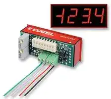
DMS-30PC-4/20S-24RS-I-C
Panel Meter, DMS-30PC-4/20S Series, Current Loop, 4 to 20mA, 3.5 Digits, 21.6 V to 26.4 V, Red
⚠️ Reference pricing provided. In case of supply shortages, we will connect you with our trusted procurement partners to ensure your project's continuity.
- Manufacturer: MURATA POWER SOLUTIONS
- Product type: Digital Panel Meters
- No. of Digits / Alpha:3-1/2; Meter Function:Current Loop Indicator; Meter Range:4mA to 20mA; Digit Height:14.2mm; Panel Cutout Height:22.35mm; Panel Cutout Width:53.85mm; Supply Voltage Mi
- SVHC: Lead (17-Jan-2022)
- Meter Range: 4mA to 20mA
- Digit Height: 14.2mm
- Product Range: -
- Meter Function: Current Loop Indicator
- Panel Cutout Width: 53.85mm
- Supply Voltage Max: 26.4V
- Supply Voltage Min: 21.6V
- Panel Cutout Height: 22.35mm
- No. of Digits / Alpha: 3-1/2
- Operating Temperature Max: 60°C
- Operating Temperature Min: 0°C
| Delivery and price | |
|---|---|
| Units per pack | 10 |
| Price | 67.22 € |
| Current stock | 100+ |
| Lead time | 30 days |
Datasheet

## **www.murata-ps.com**

## **- - DMS 30PC 4/20S**

4-20mA Input 3½ Digit Panel Meters with Full-Size LED Displays

## **FEATURES**

- Full-size, 0.56" (14.2mm), red or green LED's

- Low-power or high-intensity LED's optional

- Single +5V or optional +7.5-32V supply

- +24V Isolated-power models

- Low power consumption, 15mA from +5V

- 100Ω impedance, 2V loop drop

- DIP-switch selectable range and decimal points

- Hundreds of different input/readout combinations

- Vibration-resistant package; Reliable screw-terminal input connections

- High-quality, 20-turn, gain/span and zero/offset adjust potentiometers

- Miniature size: 2.17" x 0.92" x 1.02" 55mm x 23mm x 27mm

The DMS-30PC-4/20S Series of 4-20mA current-loop-input, 3½ digit, LED display panel meters offer an outstanding combination of electrical performance, display readability, ease-of-use, and long-term reliability. Each of the 5 models features a large (0.56"/14.2mm), red or green, LED display. Low-power or high-intensity red models are optional. Power supplies can be a single +5V or an optional, wide-range +7.5-32V (24V nominal). All DMS-30PC-4/20S meters are constructed using Murata Power Solutions' super-reliable, fi eld-proven, epoxy-encapsulated DMS-30PC digital voltmeters. The entire assembly utilizes 100% soldered connections. These are the most rugged, 4-20mA input, panel meters in the world.

Gain (span) and offset (zero) adjustments are both performed with high-precision, 20-turn potentiometers. All decimal point and range-change settings are made on a goldplated, vibration-resistant, DIP switch; there are no cumbersome solder gaps or jumpers to contend with. Connections to the current loop and the power source are both made on a rugged, four-position, screw-type terminal block .

The DMS-30PC-4/20S's user-friendly design accommodates virtually hundreds of different input-current/output-reading combinations. This eliminates the majority of requirements for more costly, long-lead-time, factory "specials"–especially in applications requiring several different-range meters. A bezel assembly, featuring secure screw fasteners and an EPDM rubber gasket, is available for applications requiring moisture and/or dust resistance.

**==> picture [497 x 266] intentionally omitted <==**

**----- Start of picture text -----**<br>
+5V<br>DMS-30PC-1<br>3½ DIGIT A/D DATA<br>CONVERTER<br>R3 R7<br>ZERO GAIN DP1 DP2 DP3<br>ADJUST ADJUST<br>Me [ie<br>BAND-GAP<br>REFERENCE<br>CIRCUIT N.C.<br>r i<br>|| | a +5V<br>ON<br>(SW1)<br>+5V DIP<br>SWITCHES<br>1 2 3 4 5 6 7 8<br>VOLTAGE<br>CONVERTER<br>1<br>T e ¢<br>TB1 1 2 TB2 1 2<br>SG9<br>+ – + –<br>+V –V<br>RS www.murata-ps.com/rohs For full details go to losGy TI LOOP INPUT4-20mA ➀ –V is not connected to meter ground  “ g : POWER SUPPLY TI INPUT /<br>**----- End of picture text -----**<br>


**www.murata-ps.com/support**

**MPM_DMS-30PC-420S.C01** Page 1 of 4

**- - DMS 30PC 4/20S**

## 4-20mA Input 3½ Digit Panel Meters with Full-Size LED Displays

## **Performance/Functional Specifi cations**

## **Ordering Information**

Typical at TA = +25°C,  unless otherwise noted.

**==> picture [244 x 378] intentionally omitted <==**

**----- Start of picture text -----**<br>
Current Loop Input Min. Typ. Max. Units<br>Full Scale Input Range +3.5 – +22 mA<br>Input Impedence – 100 – Ohms<br>Voltage Drop – – 2.0 Volts<br>Overcurrent Protection – ±0.15 ±0.3 mA<br>Performance<br>Sampling Rate 2.5 reading per second<br>Accuracy (1 minute warm-up) ±0.05%FS ±1 Count<br>Temperature Drift – ±0.15 ±0.3 Cnts/°C<br>Power Supply Requirements<br>DMS-30PC-4/20S-5RS +4.75 to +5.25Vdc at 225mA max.<br>DMS-30PC-4/20S-5GS +4.75 to +5.25Vdc at 225mA max.<br>DMS-30PC-4/20S-5RH +4.75 to +5.25Vdc at 225mA max.<br>DMS-30PC-4/20S-5RL +4.75 to +5.25Vdc at 20mA max.<br>DMS-30PC-4/20S-24RL +7.5 to +32Vdc at 30mA max.<br>DMS-30PC-4/20S-24XX-I (models) +21.6 to +26.4Vdc at 60mA max.<br>Display<br>Display Type and Size 3½ digit, 0.56"/14.2mm high LED<br>Polarity Indication "–" for negative readings<br>Overrange Indication "–1___" for negative inputs<br>"1___" for positive inputs<br>Physical/Environmental<br>Operating Temperature 0 – +60 °C<br>Storage Temperature –40 – +75 °C<br>Humidity (non-condensing) 0 – 95 %<br>Case Material Polycarbonate<br>Weight 1 ounces (28 grams)<br>**----- End of picture text -----**<br>


- ➀ **Input Grounding** : Except for the "-I"suffi x models which feature isolated current loop inputs, all other DMS-30PC-4/20S meters are supplied with their 4-20mA negative-input terminals (TB1-2, "-") internally connected to their power supply ground terminal (TB2-2, “-V”). This single-ended input confi guration is compatible with most grounded-referenced 4-20mA transmitters.

Applications in which the DMS-30PC-4/20S and its associated 4-20mA transmitter are connected to a common ground and the transmitter drives two or more loads (for example, the meter in series with a PLC) must have the meter connected as the **fi rst** device in the current loop, that is, closest to the system ground (see Figure 2). If this is not possible and/or the meter must be connected in the middle of the current loop, then'-I' suffi x models **must be used** to provide the required isolation between the meter’s current loop input and the power supply ground ("-V"). See Figures 2, 3, 4, and 5 for typical loop connections.

**DMS-30PC-4/20S-5RS-C DMS-30PC-4/20S-5GS-C DMS-30PC-4/20S-5RL-C DMS-30PC-4/20S-5RH-C DMS-30PC-4/20S-24RL-C DMS-30PC-4/20S-24RS-I-C**

+5V supply, standard-intensity red LED's +5V supply, standard-intensity green LED's +5V supply, low-power red LED's +5V supply, high-intensity red LED's +7.5V to +32V supply, low-power red LED's +24V isolated supply, standard-intensity red LED’s

**DMS-30PC-4/20S-24RH-I-C** +24V isolated supply, high-intensity red LED’s **DMS-30PC-4/20S-24BS-I-C** +24V isolated supply, high-intensity blue LED’s **DMS-30PC-4/20S-24GS-I-C** +24V isolated supply, standard-intensity green LED’s

**See www.murata-ps.com/dpm-availability for model-specifi c availability.**

## **ACCESSORIES**

**DMS-BZL1-C** Panel-mount bezel assembly **DMS-BZL2-C** Panel-mount bezel with sealing gasket **DMS-30-CP** Panel cutout punch

A panel-mount retaining clip is supplied with each model.

## **DIP-Switch Settings Table** ➁

**==> picture [245 x 20] intentionally omitted <==**

**----- Start of picture text -----**<br>
Display Reading SW1 SW2 SW3 SW4<br>**----- End of picture text -----**<br>


|Display Reading|Display Reading|SW1|SW2|SW3|SW4|
|---|---|---|---|---|---|
|||||||
|1.|000 to 100-300|On|On|On|Off|
|2.|000 to 400-600|Off|On|Off|Off|
|3.|000 to 700-1999|On|Off|Off|Off|
|4.|±100|On|On|On|Off|
|5.|±200 to ±300|On|On|Off|Off|
|6.|±400 to ±600|On|Off|Off|Off|
|7.|±700 to ±1999|Off|Off|Off|On|


- ➁ When looking up DIP-switch settings in the Table and the desired display readings happen to fall between two switch settings, try performing the adjustments with both settings to determine which one offers the better settability. Please keep in mind that the DMS-30PC meter (from which the DMS-30PC-4/20S is derived) has an accuracy specifi cation of ±2 counts (max.). Thus, it may not always be possible to obtain the exact desired display reading.

## **OPERATING AND SETUP INSTRUCTIONS**

As shipped, the DMS-30PC-4/20S is factory calibrated to read "000" for a 4mA input and "1999" for a 20mA input. The following worst-case procedure assumes the DMS-30PC-4/20S is completely mis-adjusted, i.e., both potentiometers and the DIP switches are randomly set.

- **1** . Set R7 (gain/span adjust) and R3 (zero/offset adjust) fully clockwise, roughly 20 turns, and place SW1-SW8 to OFF (down position).

- **2** . Set SW1 to ON (up position). See DIP switch setting #3.

- **3** . Apply a precision 4mA input, with proper polarity, and adjust R3 until the meter's display reads "000".

**4.** Apply a precision 20mA and adjust R7 until the display reads "1999". Repeat 3 and 4 to make sure adjustments do not affect one another.

- **5** . If desired, select the appropriate decimal point by setting either SW5, SW6 or SW7 to ON (DP1, DP2 or DP3 respectively). **NOTE:** If a display reading other than "000" to "1999" is desired, refer to the DIP-Switch Settings Table for SW1-SW4 settings.

**www.murata-ps.com/support**

**MPM_DMS-30PC-420S.C01** Page 2 of 4

**- - DMS 30PC 4/20S**

## 4-20mA Input 3½ Digit Panel Meters with Full-Size LED Displays

## **Examples**

**==> picture [240 x 37] intentionally omitted <==**

**----- Start of picture text -----**<br>
 Desired display readings are:  ON<br> 4mA ="0.00"<br>20mA = "2.00" 1 2 3 4 5 6 7 8<br>**----- End of picture text -----**<br>


**1.** Desired display readings are:

Use DIP-switch setting #1 and enable decimal point DP2 via SW6. Apply 4mA and adjust R3 so the display reads "0.00". Apply 20mA and adjust R7 so the display reads "2.00".

**2.** Desired display readings are:

**==> picture [211 x 38] intentionally omitted <==**

**----- Start of picture text -----**<br>
ON<br>12mA = "000"<br>20mA = "100" 1 2 3 4 5 6 7 8<br>**----- End of picture text -----**<br>


4mA = "–100"

Use DIP-switch setting #4. Apply 12mA and adjust R3 so the display reads "000". Apply 20mA and adjust R7 so the display reads "100". Apply 4mA and the display should read "–100". For these display readings, no decimal points are used. Set SW5, SW6 and SW7 to OFF.

**==> picture [201 x 38] intentionally omitted <==**

**----- Start of picture text -----**<br>
ON<br>4mA    = ".000"<br>12mA  = ".250" 1 2 3 4 5 6 7 8<br>**----- End of picture text -----**<br>


**3.** Desired display readings are:

This example is not as straightforward as the previous two. Notice that 12mA is exactly halfway between 4mA and 20mA. If we assume the input could go up to 20mA, the display reading would be: 2 x .250 or ".500". From the table, we can select DIP-switch setting #2 and enable DP1 via SW5. Apply 4mA and adjust R3 so the display reads ".000". Apply 12mA and adjust R7 so the display reads ".250".

## **CONNECTION DIAGRAMS**

**==> picture [237 x 106] intentionally omitted <==**

**----- Start of picture text -----**<br>
+24V<br>+ +V (TB2-1)<br>+ (TB1-1) + DMS-30PC-4/20S-24RL<br>4-20mA<br>SINGLE-ENDED<br>TRANSMITTER<br>– (TB1-2) –<br>24V GROUND –V (TB2-2)<br>**----- End of picture text -----**<br>


**Figure 2.  Typical Connections for Single-Ended Transmitters Driving Single-Ended +24V Powered Meters.**

**==> picture [240 x 107] intentionally omitted <==**

**----- Start of picture text -----**<br>
+24V<br>+ +V (TB2-1)<br>(TB1-1) + DMS-30PC-4/20S-24RL<br>LOOP-POWERED<br>TRANSMITTER – 4-20mA<br>(TB1-2)<br>N.C. –<br>–V (TB2-2)<br>24V GROUND<br>**----- End of picture text -----**<br>


**Figure 3.  Typical Connections for Loop-Powered Transmitters Driving Single-Ended Meters.**

**==> picture [237 x 145] intentionally omitted <==**

**----- Start of picture text -----**<br>
+24V<br>+V (TB2-1)<br>DMS-30PC-4/20S-24RL-I (TB2-2)<br>–V<br>+<br>+ + (TB1-1) (TB1-2) – +<br>SINGLE-ENDED 4-20mA PLC or OTHER<br>TRANSMITTER SINGLE-ENDED<br>DEVICE<br>4-20mA<br>– –<br>24V GROUND<br>**----- End of picture text -----**<br>


**Figure 4.  Typical Connections for Isolated-Supply Meters in Series with an Auxiliary Device**

**==> picture [246 x 120] intentionally omitted <==**

**----- Start of picture text -----**<br>
+24V +5V<br>+ +V (TB2-1)<br>+ (TB1-1) + DMS-30PC-4/20S-24RL<br>4-20mA<br>LOOP<br>TRANSMITTER<br>– (TB1-2) –<br>24V GROUND –V (TB2-2)<br>5V GROUND<br>**----- End of picture text -----**<br>


**Figure 5.  Typical Connections for +5V Powered Meters. Note that 5V Ground and 24V Ground are Tied Together Inside the Meter.**

**==> picture [227 x 102] intentionally omitted <==**

**----- Start of picture text -----**<br>
DMS-30PC-4/20S-24XX-I<br>**----- End of picture text -----**<br>


**Figure 6. Typical Connections for Loop-Powered Transmitters Driving Isolated-Supply Meters (-I part number suffi x).**

**www.murata-ps.com/support**

**MPM_DMS-30PC-420S.C01** Page 3 of 4

**- - DMS 30PC 4/20S**

## 4-20mA Input 3½ Digit Panel Meters with Full-Size LED Displays

**==> picture [478 x 222] intentionally omitted <==**

**----- Start of picture text -----**<br>
MECHANICAL DIMENSIONS: Inches (mm)<br>TOLERANCES:  2 PL DEC ±0.02 (±0.51)<br>3 PL DEC ±0.010 (±0.254)<br>WIRE SIZE:  18 to 26 AWG  1.33 1<br>(Solid or stranded) (33.8) 1.02<br>STRIPPING LENGTH:  0.20" (5.08mm) (25.9) 0.040<br>(1.02)<br>2.09 0.04 0.84<br>(53.09) (1.02) (21.34)<br>2.17 0.92<br>(55.12) (23.37)<br>Zero/Offset DIP 1 Depth dimension for the DMS-30PC-4/20S-24RL model only.<br>Adjust Switches<br>Back View 12 D1 ON 1 Front View<br>R10<br>R3 SW1<br>Zero<br>Adjust R12 1 2 3 4 5 6 7 8 SG10<br>R6 R9 TB1 TB2<br>R1 R8 + – + – U2<br>Gain R7R7 SG9<br>Adjust 1 2 1 2<br>R5 R4 R2 + – + – DP1 DP2 DP3<br>Gain/Span Loop Power (SW5) (SW6) (SW7)<br>MADE IN USA DMS-30PC-4/20S<br>**----- End of picture text -----**<br>


**==> picture [188 x 98] intentionally omitted <==**

**----- Start of picture text -----**<br>
Zero/Offset DIP<br>Adjust Switches<br>Back View 12 D1 ON 1<br>R10<br>R3 SW1<br>Zero<br>Adjust R12 1 2 3 4 5 6 7 8 SG10<br>R6 R9 TB1 TB2<br>R1 R8 + – + – U2<br>Gain R7R7 SG9<br>Adjust 1 2 1 2<br>R5 R4 R2 + – + –<br>Gain/Span Loop Power<br>Adjust Input Input<br>**----- End of picture text -----**<br>


**==> picture [113 x 5] intentionally omitted <==**

**----- Start of picture text -----**<br>
OPTIONAL BEZEL (DMS-BZL1 and DMS-BZL2)<br>**----- End of picture text -----**<br>


**==> picture [170 x 231] intentionally omitted <==**

**----- Start of picture text -----**<br>
0.187<br>#2-56 INSERT (4.75)<br>FRONT VIEW 0.156 (3.96) DEEP<br>1.270<br>(32.26)<br>2.55 (64.77)<br>RECOMMENDED DRILL AND PANEL CUTOUT DIMENSIONS<br>0.116<br>I NTERNAL CORNER RADII: (2.95)<br>0.032 (0.81) MAX.<br>1.07 0.878<br>(27.18) PANEL CUTOUT (22.30)<br>2.118 (53.80)<br>2.35 (59.69)<br>0.096<br>0.093 (2.362) DIAMETER (4 REQUIRED) (2.44)<br>ONLY WHEN USING OPTIONAL BEZEL ASSEMBLY<br>**----- End of picture text -----**<br>


**==> picture [220 x 204] intentionally omitted <==**

**----- Start of picture text -----**<br>
PANEL<br>OPTIONAL<br>GASKET<br>BEZEL<br>RETAINING CLIP INSTALLATION<br>PANEL<br>A panel-mount retaining clip is supplied with all models<br>MADE IN USA<br>MADE IN USA<br>**----- End of picture text -----**<br>


## Murata Power Solutions, Inc.

11 Cabot Boulevard, Mansfi eld, MA 02048-1151 U.S.A. ISO 9001 and 14001 REGISTERED

## **This product is subject to the following operating requirements and the Life and Safety Critical Application Sales Policy: Refer to: http://www.murata-ps.com/requirements/**

Murata Power Solutions, Inc. makes no representation that the use of its products in the circuits described herein, or the use of other technical information contained herein, will not infringe upon existing or future patent rights. The descriptions contained herein do not imply the granting of licenses to make, use, or sell equipment constructed in accordance therewith. Specifi cations are subject to change without notice. _**© 2015 Murata Power Solutions, Inc.**_

**www.murata-ps.com/support**

**MPM_DMS-30PC-420S.C01** Page 4 of 4
Updated at June 9, 2026
About Novapart
Novapart is a B2B electronic component broker specialising in stock shortages and cost reduction. We source hard-to-find parts and identify compliant alternatives across a catalogue of 410,000+ components from 500+ manufacturers.
Learn more →Stock Shortage Specialist
When a component is unavailable, discontinued or has an unacceptable lead time, we tap into our network of vetted European and Asian distributors to source what you need — without compromising on quality or traceability.
Request a quote →Compliant Alternatives
We identify pin-to-pin, electrically equivalent substitutes that meet the same certifications (RoHS, AEC-Q100, REACH) as your original specification — validated against datasheets, not just part numbers. Often at a lower cost.
BOM Analysis service →