
Image not available
Illustrative purposes only

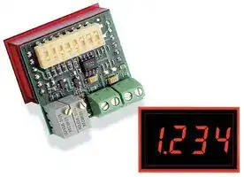
DMS-20PC-0/5-24RL-C.
PROCESS METER
⚠️ Reference pricing provided. In case of supply shortages, we will connect you with our trusted procurement partners to ensure your project's continuity.
- Manufacturer: MURATA POWER SOLUTIONS
- Product type: Digital Panel Meters
- Meter Range: 0V to 5V / 0V to 10V
- Digit Height: 9.4mm
- Meter Function: DC Voltage
- Panel Cutout Width: 33.93mm
- Supply Voltage Max: 40VDC
- Supply Voltage Min: 4.75VDC
- Panel Cutout Height: 21.29mm
- No. of Digits / Alpha: 3-1/2
- Operating Temperature Max: 60°C
- Operating Temperature Min: 0°C
| Delivery and price | |
|---|---|
| Units per pack | 100 |
| Price | 66.36 € |
| Current stock | 50+ |
| Lead time | 7 days |
Datasheet

## **www.murata-ps.com**

## **- - DMS 20PC 0/5 Series**

0-5V and 0-10V Input 3½ Digit, LED Display Process Control Monitors

## **FEATURES**

- Accepts 0-5V and 0-10V inputs

- Large, easy-to-read, 0.37"/9.4mm LED display

- Choice of 5 LED power/color options

- High input impedance, 100kΩ

- +5V to +40V model draws 9mA typ.

- Miniature size: 1.38" x 1.25" x 0.95"

- High-quality, 20-turn, span (gain) and zero (offset) adjustments

- DIP-switch selectable range and decimal points

- Vibration-resistant package; Reliable screw-terminal input connections

- Hundreds of different input/readout combinations

Murata Power Solutions’ DMS-20PC-0/5 Series are the world's smallest, full-featured, 0-5V input process control monitors. Their large, easy-to-read, 0.37"/9.4mm LED displays are available in a choice of 4 LED color/intensity options: standard red, standard green, super-bright red, and low-power red. Two power supply input ranges are also available: the industry-standard +5V and a wide-range +5V to +40V (which typically draws 9mA at +24V).

Gain (span) and offset (zero) adjustments are performed with on-board, precision, 20-turn potentiometers. All decimal-point and range-change selections are made on an 8-position, vibration-resistant, gold-plated DIP switch. Unlike competitive meters, there are no jumpers or solder gaps to open or close, and to further enhance reliability, the entire assembly utilizes 100% soldered connections. Both power-supply and input-signal connections are made via reliable screw-type terminal blocks.

The DMS-20PC-0/5's DIP switch and potentiometers accommodate hundreds of inputvoltage/output-reading combinations. This practically eliminates the need for more costly, long-lead-time, factory "specials" in applications which use several different-range meters. A supplied bezel assembly––featuring metal fasteners and a rubber gasket––simplifi es panel mounting and also provides excellent resistance to environmental dust and moisture. All these outstanding features combine to make the DMS-20PC-0/5 the perfect meter for

prototype and OEM, 0-5V input, process control monitoring.

**==> picture [541 x 290] intentionally omitted <==**

**----- Start of picture text -----**<br>
Lo SIMPLIFIED SCHEMATIC DIAGRAM<br>3½ Digit DATA<br>A/D Converter<br>–5V +5V DP1 DP2 DP3<br>N.C.<br>R3 R7<br>Zero Gain ON<br>Adjust Adjust<br>DIP Switches<br>UE ee<br>1 2 3 4 5 6 7 8<br>Pt TT<br>N.C.<br>+5V<br>DC/DC<br>Band-Gap Converter –5V<br>Reference<br>Circuit TB1 1 2 TB2 1 2<br>+ CI – + L___] –<br>+5V –5V HI LO +V –V<br>Signal Input Power Supply Input<br>COMPLIANT For full details go to<br>gis www.murata-ps.com/rohs © Figure 1. DMS-20PC-0/5 simplifi ed schematic<br>**----- End of picture text -----**<br>


**www.murata-ps.com/support**

**MPM_DMS20pc_5V.C01** Page 1 of 4

## **- - DMS 20PC 0/5 Series**

## 0-5V and 0-10V Input 3½ Digit, LED Display Process Control Monitors

## **Performance/Functional Specifi cations**

## **TECHNICAL NOTES**

Typical at TA = +25°C,  unless otherwise noted.

|**Inputs**|**Min.**|**Typ.**|**Max.**|**Units**|
|---|---|---|---|---|
|**Full Scale Input Range**➀|4.9|5.0|5.1|Volts|
|**Input Impedence**|100|–|140|kΩ|
|**Overvoltage Protection**➁|–|–|±40|Volts|
|**Performance**|||||
|**Sampling Rate**|2.5 reading per second||||
|**Accuracy**(1 minute warm-up):||±0.05%FS ±1 Count|||
|**Temperature Drift**(0 to +60°C)|–|±0.15|±0.3|Cnts/°C|
|**Power Supply Requirements**|||||
|DMS-20PC-0/5-5RS (90mA max.)|+4.75|+5.00|+5.25|Volts|
|DMS-20PC-0/5-5GS, -5BS (120mA max.)|+4.75|+5.00|+5.25|Volts|
|DMS-20PC-0/5-5RL  15mA max.)|+4.75|+5.00|+5.25|Volts|
|DMS-20PC-0/5-5RH (90mA max.)|+4.75|+5.00|+5.25|Volts|
|DMS-20PC-0/5-24RL (15mA max.)|+4.75|–|+40.0|Volts|
|**Display**|||||
|**Display Type and Size**|3½ digit, 0.37"/9.4mm high LED||||
|**Polarity Indication**|"–" for negative VIN||||
|**Overrange Indication**|"–1___" for negative inputs<br>"1___" for positive inputs||||
|**Physical/Environmental**|||||
|**Operating Temperature**|0|–|+60|°C|
|**Storage Temperature**|–20|–|+75|°C|
|**Humidity (non-condensing)**|0|–|95|%|
|**Case Material**||Polycarbonate|||
|**Weight**|0.6 ounces (17 grams)||||


- ➀ The DMS-20PC-0/5 can also be used in most 0-10V applications. See the section on 0-10V inputs for more information. See Note 3 on Table 1.

- ➁ INPUT LO (TB1 "–LO") is internally connected to the power return (TB2 "–V"). Overvoltage specifi cations apply to the INPUT HI (TB1 "+HI") connection.

**1.  Input Confi guration** : The DMS-20PC-0/5 has its input low terminal (TB1 "LO") internally connected to the power supply ground terminal (TB2 "–V"). This connection effectively places the meter's input in a single-ended confi guration. In some applications, single-ended inputs can cause ground-loop induced errors (the meter's display becomes unstable or bounces). This occurs because the LED drive currents fl ow through both the –V terminal and the signal LO terminal.

If suspected ground-loop errors are encountered, and the input signal LO terminal is externally connected to –V somewhere else in the system, try removing the connection to TB1 "LO.” Inputs which have no ground-return connection to –V (commonly referred to as "fl oating inputs") must have their most negative potential  tied to TB1 "LO." Please consult Murata Power Solutions for more information.

Applications which require electrical isolation between the input signal source and the system power supply must use a separate transformer-isolated supply to power the meter.

**2.  Panel Mounting** : In most standard through-the-panel installations, the DMS-20PC-0/5 must be secured to the panel with DMS-BZL4 bezel assemblies (see the Mechanical Specifi cations section for more information).

## **OPERATING AND SETUP INSTRUCTIONS**

As shipped, the DMS-20PC-0/5 is factory calibrated to read "000" for a 0.0V input and "1999" for a 5.0V input. The following worst-case procedure assumes the DMS-20PC-0/5 is completely mis-adjusted, i.e., both potentiometers and the DIP switches are randomly set.

1. Set R7 (full scale span/gain adjust) and R3 (zero/offset adjust) fully clockwise, roughly 22 turns, and place SW1-SW8 to OFF (down position).

2. Select DIP switch setting #1 in Table 1.

3. Apply a precision 0.0V input and adjust R3 until the meter's display reads "000.”

## **Ordering Information**

**DMS-20PC-0/5-5RS-C** +5V supply, standard-intensity red LED's **DMS-20PC-0/5-5GS-C** +5V supply, standard-intensity green LED's **DMS-20PC-0/5-5BS-C** +5V supply, bright blue LED's **DMS-20PC-0/5-5RL-C** +5V supply, low-power red LED's **DMS-20PC-0/5-5RH-C** +5V supply, high-intensity red LED's **DMS-20PC-0/5-24RL-C** +5V to +40V supply, low-power red LED's

## **DMS-20-CP** Panel cutout punch

Note: A DMS-BZL4 bezel assembly with a sealing gasket is supplied with each meter.

**See www.murata-ps.com/dpm-availability for model-specifi c availability.**

4. Apply a precision 5.0V input and adjust R7 until the meter's display reads "1999.” Repeat steps 3 and 4 to make sure the adjustments do not affect one another.

5. Select the appropriate decimal point by setting SW6, SW7 or SW8 to ON (DP1, DP2 or DP3 respectively).

NOTE: The "000" to "1999" display readings referred to in the instructions above are for illustrative purposes only. If other display readings such as "000" to "1200" are desired, refer to the DIPSwitch Settings Tables for SW1-SW4 settings. (SW5 is reserved for future use, it has no affect on display operation.) The initial setting of R3 and R7 fully clockwise is recommended in the adjustment procedure for all the following examples.

**www.murata-ps.com/support**

**MPM_DMS20pc_5V.C01** Page 2 of 4

## **- - DMS 20PC 0/5 Series**

0-5V and 0-10V Input 3½ Digit, LED Display Process Control Monitors

## **Examples (0-5V Inputs)**

**==> picture [240 x 37] intentionally omitted <==**

**----- Start of picture text -----**<br>
1.  Desired display readings are:  ON<br> 0.0V input = "0.00"<br> 5.0V input = "6.00" 1 2 3 4 5 6 7 8<br>**----- End of picture text -----**<br>


Use DIP-switch setting #3 in Table 1 and enable decimal point DP2 via SW7.  Apply 0.0V and adjust R3 so the display reads "0.00.” Apply 5.0V and adjust R7 so the display reads "6.00.”

**==> picture [240 x 37] intentionally omitted <==**

**----- Start of picture text -----**<br>
2.  Desired display readings are: ON<br> 0.0V input = "000"<br> 5.0V input = "800" 1 2 3 4 5 6 7 8<br>**----- End of picture text -----**<br>


Use DIP-switch setting #2 in Table 1. Apply 0.0V and adjust R3 so the display reads "000.” Apply 5.0V and adjust R7 so the display reads "800.”  For these display readings, no decimal points are used. Set SW6, SW7 and SW8 to OFF.

**3.** Desired display readings are:

**==> picture [229 x 37] intentionally omitted <==**

**----- Start of picture text -----**<br>
 Desired display readings are: ON<br> 0.0V input = .”000"<br> 5.0V input = .”250" 1 2 3 4 5 6 7 8<br>**----- End of picture text -----**<br>


Use DIP-switch setting #5 in Table 1 and enable decimal point DP1 via SW6. Apply 0.0V and adjust R3 so the display reads "000.” Apply 5.0V and adjust R7 so the display reads .”250.”

**Table 1.** 0-5V DIP-Switch Settings ➂

|~~**Display Reading**~~|~~**Display Reading**~~|~~**SW1**~~|~~**SW2**~~|~~**SW3**~~|~~**SW4**~~|
|---|---|---|---|---|---|
|0.0V Input|5.0V Input|||||
|1.  000|1200-1999|Off|Off|Off|Off|
|2.  000|700-1200|On|Off|Off|Off|
|3.  000|400-700|Off|On|Off|Off|
|4.  000|300-400|Off|Off|On|Off|
|5.  000|190-300|Off|On|On|Off|
|6.  000|120-190|Off|Off|On|On|
|7.  000|100-150|Off|On|On|On|
|8.  000|90-140|On|On|On|On|


➂ The DMS-20PC-0/5 is optimized for handling 5V signal ranges that are positioned between –0.1V and +6.0V. As such, input ranges can be anywhere between –0.1V to +4.9V and +1.0V to +6.0V as long as their full range is 5 Volts. The meter's zero/offset potentiometer (R3) has enough adjustment range to produce a "000" display reading for input signal levels between –0.1V and +1.0V.

**==> picture [245 x 36] intentionally omitted <==**

**----- Start of picture text -----**<br>
4.   Desired display readings are: ON<br> 1.0V input = "000"<br> 6.0V input = "090" 1 2 3 4 5 6 7 8<br>**----- End of picture text -----**<br>


Even though this input is positioned between +1.0V and +6.0V, it still meets the 5V full scale input range listed in the Functional Specifi cations section. Use DIP-switch setting #8 in Table 1. Apply 1.0V and adjust R3 so the display reads "000.” Apply 6.0V and adjust R7 so the display reads "090.” With this type of input, it is advisable to recheck both input levels to be sure the potentiometer settings do not affect one another.

## **0-10V Inputs**

While the DMS-20PC-0/5 is optimized for operation with 0-5V inputs, its versatile input stage can also accommodate most 0-10V applications. The meter's zero/offset potentiometer (R3) has enough adjustment range to produce a "000" display reading with input signal levels between –0.1V and +1.0V. Table 2. summarizes the available ranges when the DMS-20PC-0/5 is used with 0-10V inputs.

## **Example** (0-10V Inputs)

**==> picture [244 x 38] intentionally omitted <==**

**----- Start of picture text -----**<br>
1.  Desired display readings are: ON<br> 0.0V input = "000"<br> 10.0V input = "500" 1 2 3 4 5 6 7 8<br>**----- End of picture text -----**<br>


Use DIP switch setting #4 in Table 2. Apply 0.0V and adjust R3 so the display reads "000.” Apply 10.0V and adjust R7 so the display reads "500.”

**Table 2.** 0-10V DIP-Switch Settings

|~~**Display Reading**~~|~~**Display Reading**~~|~~**SW1**~~|~~**SW2**~~|~~**SW3**~~|~~**SW4**~~|
|---|---|---|---|---|---|
|0.0V Input|10.0V Input|||||
|1.  000|1400-1999|On|Off|Off|Off|
|2.  000|800-1400|Off|On|Off|Off|
|3.  000|600-800|Off|Off|On|Off|
|4.  000|380-600|Off|On|On|Off|
|5.  000|240-380|Off|Off|On|On|
|6.  000|200-300|Off|On|On|On|
|7.  000|180-280|On|On|On|On|


Please note the DMS-20PC digital panel meter from which the DMS-20PC-0/5 is derived has an accuracy specifi cation of ±2 counts (max.). Thus, it may not always be possible to obtain the exact desired display readings.

**www.murata-ps.com/support**

**MPM_DMS20pc_5V.C01** Page 3 of 4

## **- - DMS 20PC 0/5 Series**

## 0-5V and 0-10V Input 3½ Digit, LED Display Process Control Monitors

## **MECHANICAL SPECIFICATIONS**

**==> picture [431 x 234] intentionally omitted <==**

**----- Start of picture text -----**<br>
0.95<br>(24.1)<br>0.040<br>(1.02)<br>0.44<br>Back View 0.040 1.30 0.040 0.80 (11.2)<br>(1.02) (33.0) (1.02) (20.3) TYP.<br>DIP 12 ON 1 (35.1)1.38 (22.4)0.88<br>Switches 1 2 3 4 5 6 7 8 (31.8)1.25<br>Front View<br>Zero/Offset + – + –<br>Adjust R3 R7<br>Gain/Span + – + –<br>Adjust TB1 TB2<br>Signal Power<br>Input Input<br>MADE IN USA<br>DMS-20PC-0/5<br>**----- End of picture text -----**<br>


TOLERANCES: 2 PL DEC ±0.02 (±0.51) 3 PL DEC ±0.010 (±0.254) WIRE SIZE: 18 to 26 AWG (Solid or stranded) STRIPPING LENGTH: 0.20" (5.08mm)

**==> picture [62 x 15] intentionally omitted <==**

**----- Start of picture text -----**<br>
DP1 DP2 DP3<br>(SW6) (SW7) (SW8)<br>**----- End of picture text -----**<br>


## **BEZEL INSTALLATION AND RECOMMENDED DRILL AND PANEL CUTOUT**

**==> picture [169 x 188] intentionally omitted <==**

**----- Start of picture text -----**<br>
#2-56 INSERT 0.187<br>0.156 (3.96) DEEP (4.75)<br>FRONT VIEW (32.51)1.280<br>1.826 (46.38)<br>0.116 (2.95)<br>INTERNAL CORNER RADII:<br>0.032 (0.81) MAX.<br>(27.18)1.07 PANEL CUTOUT (21.29)0.838<br>0.093 (2.362) DIA 1.336 (33.93) 0.145 (3.68)<br>(4 REQUIRED) 1.626 (41.30)<br>**----- End of picture text -----**<br>


**==> picture [178 x 129] intentionally omitted <==**

**----- Start of picture text -----**<br>
BEZEL INSTALLATION<br>PANEL<br>GASKET<br>BEZEL<br>**----- End of picture text -----**<br>


Murata Power Solutions, Inc. 11 Cabot Boulevard, Mansfi eld, MA 02048-1151 U.S.A. ISO 9001 and 14001 REGISTERED

**This product is subject to the following operating requirements and the Life and Safety Critical Application Sales Policy: Refer to: http://www.murata-ps.com/requirements/**

Murata Power Solutions, Inc. makes no representation that the use of its products in the circuits described herein, or the use of other technical information contained herein, will not infringe upon existing or future patent rights. The descriptions contained herein do not imply the granting of licenses to make, use, or sell equipment constructed in accordance therewith. Specifi cations are subject to change without notice. _**© 2015 Murata Power Solutions, Inc.**_

**www.murata-ps.com/support**

**MPM_DMS20pc_5V.C01** Page 4 of 4
Updated at February 9, 2023
About Novapart
Novapart is a B2B electronic component broker specialising in stock shortages and cost reduction. We source hard-to-find parts and identify compliant alternatives across a catalogue of 410,000+ components from 500+ manufacturers.
Learn more →Stock Shortage Specialist
When a component is unavailable, discontinued or has an unacceptable lead time, we tap into our network of vetted European and Asian distributors to source what you need — without compromising on quality or traceability.
Request a quote →Compliant Alternatives
We identify pin-to-pin, electrically equivalent substitutes that meet the same certifications (RoHS, AEC-Q100, REACH) as your original specification — validated against datasheets, not just part numbers. Often at a lower cost.
BOM Analysis service →