


DMR35-ACV1-AC1-R
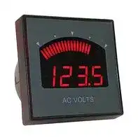
Digital Panel Meter, 3.5 Digit, AC Voltage, 0 to 5 VAC, 0 to 50 VAC, Red Display
- Manufacturer: MURATA
- Product type: Digital Panel Meters
- SVHC: No SVHC (04-Feb-2026)
- Meter Range: 0VAC to 5VAC, 0VAC to 50VAC
- Digit Height: 11.4mm
- Product Range: DMR35-ACV Series
- Meter Function: AC Voltage
- Panel Cutout Width: -
- Supply Voltage Max: 264VAC
- Supply Voltage Min: 100VAC
- Panel Cutout Height: -
- No. of Digits / Alpha: 3.5
- Operating Temperature Max: 50°C
- Operating Temperature Min: 0°C
| Delivery and price | |
|---|---|
| Units per pack | 1 |
| Price | 89.96 € |
| Current stock | 10+ |
| Lead time | 30 days |
AC Voltmeter

## |auRataMurata Power Solutions| Ps

## DMR35-ACV Series

## FEATURES

- Full-scale measurement of AC voltage

- Highly visible 3-1/2 digit LED display with adjustable intensity

- Responsive bar-graph display provides indication of rapidly changing inputs, emulating analog movement meters

- Measurement accuracy within 1% of reading + 4 counts

- Selectable True RMS  or Average Reading  modes

- Switch configurable settings simplify adaptation for use in a wide range of applications

- Rugged Polycarbonate housing

- Mechanical drop-in replacement for common analogmovement meters

~~Ws~~ File: E156931 Vol. D1 :

- Operates from an external 100-264 VAC power supply

- Low power consumption, typically 15 mA at 120 VAC

- Two-year warranty

For full details go to **www.murata-ps.com/rohs**

## PRODUCT OVERVIEW

DMR35-ACV series panel meters measure AC voltage, from 5 to 300V, displayed in up to 3-1/2 digits of resolution. The 21-segment bar-graph is tracks rapidly changing inputs.

Rear-accessible DIP switches are provided to set Measurement Mode, Input Range, and Display Brightness.

This meter is capable of displaying True RMS Mode,  for compatibility with modern digital multimeters as well as Average Reading Mode, for compatibility with legacy analog meters.

Basic safety isolation between the measurement and power inputs is provided.

## APPLICATIONS

These meters are packaged in a rugged polycarbonate housing and designed for drop-in replacement of most 2-1/2” form-factor analog meters.

Ideal for use in laboratory instrumentation, factory automation, and other applications requiring precise AC voltage monitoring.

This meter requires an external power source of between 100-264 VAC.

- www.murata ps.com

DMR35-ACV.A01.D04   Page 1 of 11

AC Voltmeter

## DMR35-ACV Series

## Murata Power Solutions

ORDERING INFORMATION: MODEL NUMBER DESCRIPTION DMR35-ACV1-AC1-R AC Voltmeter, 0-5 to 0-50 VAC ranges, 100-264 VAC powered, red display DMR35-ACV2-AC1-R AC Voltmeter, 0-50 to 0-300 VAC ranges, 100-264 VAC powered, red display

## SIMPLIFIED BLOCK DIAGRAM

**==> picture [69 x 9] intentionally omitted <==**

**----- Start of picture text -----**<br>
Rear Panel View:<br>**----- End of picture text -----**<br>


- www.murata ps.com

DMR35-ACV.A01.D04   Page 2 of 11

AC Voltmeter

## DMR35-ACV Series

## Murata Power Solutions

|SPECIFICATIONS:|SPECIFICATIONS:|SPECIFICATIONS:|SPECIFICATIONS:|SPECIFICATIONS:|SPECIFICATIONS:|SPECIFICATIONS:|
|---|---|---|---|---|---|---|
|Measurement Performance|Min|Typ.|Max|||Units|
|Measurement Ranges|||||||
|DMR35-ACV1|0-5,0-10,0-15,0-25|||||VAC|
|DMR35-ACV2|0-50,0-150,0-250,0-300|||||VAC|
|Accuracy (25 °C)<br>60 Hz sinusoidal input|1 % Reading +4 counts||||||
|Measurement Modes|Mean Reading (Average)and True RMS,DIP Switch selectable||||||
|Measurement FrequencyRange1|20||120|||Hz|
|Measurement Crest Factor|||3||||
|Temperature Stability (full-scale measurement)||0.02||||% /°C|
|Input Impedance|||||||
|DMR35-ACV1||100||||kΩ|
|DMR35-ACV2||1||||MΩ|
|Isolation/Hipot (power input terminals to measurement input<br>terminals)2||2150||||VDC|
|1Frequency range over which measurement is stable to within ±1% with sinusoidal input<br>2100% Tested inproduction,applied for 2 seconds|||||||
|Power Supply Characteristics|Min|Typ.|Max|||Units|
|Power SupplyVoltage|100||264|||VAC|
|Power SupplyFrequency|47||63|||Hz|
|Power SupplyCurrent|||||||
|…at 120 VAC||15||||mA|
|…at 240 VAC||10||||mA|
|Display & User Interface|||||||
|Display Type & Size|3-1/2 digit 7-segment, 11.4mm (0.45 in.) high<br>21 segment curved bar-graph||||||
|DisplayColor|Red(625nm)||||||
|Decimal Point Selection|Automatic||||||
|Out-of-range Indication|Flashingdisplay||||||
|Measurement Range Selection|Dipswitch selectable(4 ranges)||||||
|Measurement Mode Selection|Dipswitch selectable(Average-readingor RMS)||||||
|DisplayIntensityControl|Dipswitch selectable(4 ranges)||||||
|Terminal Blocks|||||||
|Wire Size|14-24 AWG||||||
|Insulation StripLength|6mm(0.24 in.)||||||
|Screw TighteningTorque|0.4 N-m(3.5 lb.-in)||||||
|OperatingTemperature4|0||50||°C||
|Storage Temperature|-40||70||°C||
|Humidity (non-condensing)|0||85||%RH||
|Sealing (front face,when installed with includedgasket)|Splash and dust resistant||||||
|Mountingscrews(4 included)|#4-20 0.5” thread forming||||||
|Screw TighteningTorque|9 in-lb(1 N-m)||||||
|Panel thickness when used with included mountingscrews|0.062 in.(1.6mm)||0.25 in.(6.3mm)||||
|Weight|2.5(71)|||oz.(g)|||
|4Maximum operating temperature applies to both front face and rear of housing. Unit must not be installed so that the rear of housing is exposed to more than the maximum operating<br>temperature whenpowered.|||||||


4 Maximum operating temperature applies to both front face and rear of housing. Unit must not be installed so that the rear of housing is exposed to more than the maximum operating temperature when powered.

- www.murata ps.com

DMR35-ACV.A01.D04   Page 3 of 11

AC Voltmeter

## DMR35-ACV Series

## Murata Power Solutions

## NOMINAL OUTLINE DIMENSIONS

## Panel Drill Template

## Panel Mounting Details

|ITEM<br>NO.<br>~~i~~|DESCRIPTION<br>~~i~~|QTY.|NOTES|
|---|---|---|---|
|1|DMR35panel meter|1|Shown for reference|
|2|Gasket|1|Included with DMR35 panel<br>meter|
|3|Provided screws are<br>compatible with panel<br>Thickness:<br>1/16” –¼”|REF|Shown for reference|
|4|4-20 x ½” thread forming<br>screw|4|Torque: 9 IN-LB (1 N-m)<br>Included with DMR35 panel<br>meter|


- www.murata ps.com

DMR35-ACV.A01.D04   Page 4 of 11

AC Voltmeter

## DMR35-ACV Series

## Murata Power Solutions

## OPERATION, MEASUREMENT TYPE, CAPABILITIES

The DMR35 series meters employ precision, low power electronics to provide high performance full-scale measure of AC voltage. The following illustrations describe the features and operation to simplify deployment in a wide variety of systems. FRONT PANEL & FRONT PANEL LAYOUT AND FUNCTION

Bar-graph Display: The 21-segment bar-graph display responds quickly and smoothly like an analog meter movement to aid in reading rapidly changing measurements.

Numeric Display: The 3-1/2 digit display provides precise measurements for steady-state and slowly changing measurement values.

## REAR PANEL LAYOUT AND SCREW TERMINAL CONNECTIONS

|Terminal<br>Position No.|Name|Function|
|---|---|---|
|1<br>2|PWRA<br>PWRB|Power supply input terminals (100-264 VAC, 50/60Hz)|
|3<br>4|INA<br>INB|Voltage measurement input terminals|


DIP Switch: comprised of five individual switches to configure display intensity (SW1-SW2), measurement mode (SW3), and measurement range (SW4-SW5) Notes:

- 1) Ensure all screw-terminals are tightened in accordance with the torque specifications for reliable operation.

- 2) Stranded wire is recommended for high-vibration applications.

- 3) Basic safety isolation is provided between the meter’s measurement and input power electronics, no connection from the measurement-point and AC input power is required

- 4) External fusing for input power and or measurement source may be required. It is incumbent upon the end-user to ensure all local electrical safety regulations and external fusing requirements are followed where-ever this meter is deployed

## CONNECTION EXAMPLES

In this application, the meter is configured for simple voltage measurement where the meter shares a common load and power connection point.

In this application, the meter is monitoring a voltage independent of the meter’s power supply circuit. In such applications, the user must ensure the voltage between the power and measurement terminals does not exceed the meter’s isolation voltage rating.

- www.murata ps.com

DMR35-ACV.A01.D04   Page 5 of 11

## /muRata |Ps

## DMR35-ACV Series

AC Voltmeter

## METER CONFIGURATION

Five configuration switches are provided to configure measurement range, measurement mode, and display intensity.

## Measurement Range: Switches 4 and 5:

||||Switch Settings|Switch Settings|Switch Settings|Switch Settings|Switch Settings|Switch Settings|DMR35 Model|DMR35 Model|DMR35 Model|
|---|---|---|---|---|---|---|---|---|---|---|---|
||4|5||||||Dipswitch|-ACV1||-ACV2|
||OFF|OFF|OFF|||||‘00g|0-5 VAC||0-50 VAC|
||OFF|ON|ON|||||0008|0-10 VAC||0-150 VAC|
||ON|OFF|OFF|||||‘00h|0-15 VAC||0-250 VAC|
||ON|ON|ON|||||000|0-25 VAC||0-300 VAC|
|Measurement Mode:Switch 3:|||Switch 3:|||||||||
||3||Switch Settin<br>~~|~~|||||Switch Settings<br>Dipswitch<br>ON|Measurement Mode|||
||OFF|||||||000|‘Average’ Reading<br>(RMS Adjusted)|||
||ON|||||||(000|RMS Reading|||
|Display Intensity:Switches 1 and 2:|||||Switches 1 and 2:|Switches 1 and 2:||||||
||||Switch Settings|||||Switch Settings||||
||SW1|SW2|||||||Dipswitch|Display Intensity|||
|||||||||ON||||
||OFF|OFF||||||aon|Low|||
||OFF|ON|ON|||||00|Medium|||
||ON|OFF||||||AON|High|||
||ON|ON|ON|||||iN|High 2<br>(Subtle increase in intensity compared with ‘High’ setting)|||


- www.murata ps.com

DMR35-ACV.A01.D04   Page 6 of 11

AC Voltmeter

## DMR35-ACV Series

## Murata Power Solutions

RMS MEASUREMENT MODE VS. AVERAGE MEASUREMENT MODE.

These meters are capable of both RMS and Average Reading (RMS adjusted) measurement modes:

RMS (Root-Mean-Square) Mode –   RMS voltage can be thought of as the equivalent DC voltage required to dissipate a given amount of energy in a resistive load. Benefit of RMS measurements:

- Provides an indication of delivered power, independent of the exact waveform being measured

- Comparable with most high-quality handheld multimeters that tend to adapt RMS measurement

RMS Measurement Signal Flow.

Average-Reading mode – In this mode, the meter measures the average rectified value of the voltage waveform. Since the resulting measurement is different from the RMS measurement, it is typically ‘adjusted’ to match the RMS measurement value for the case of a sinusoidal waveform. The benefit of this measurement mode it that it enables DMR35 meters to provide measurements comparable to those provided by many electromechanical analog meters. The block diagram below shows the signal-processing performed in making RMS-adjusted average mode measurements.

RMS-adjusted Average Measurement Signal Flow

Note that both measurement modes adapt a digital high-pass filter, placed after the ADC, to remove any DC bias from the input signal and generate a signal that is symmetric about zero. As a result, these meters only measure the AC component of the input signal, and not the DC component – a DC signal presented to the meter will read as zero.   Significant amounts of DC input signal, however, may force the meter’s ADC into over-range and reduce measurement accuracy. For this reason, the DMR35-ACVx series of meters should not be used to measure currents having a significant DC component.

## Crest Factor

When making AC measurements, the shape of the waveform to be measured can influence the measurement results. One of the most basic metrics used to quantify waveform shape is crest factor, which is defined as the ratio between the waveform’s peak value and its RMS value.

**==> picture [126 x 25] intentionally omitted <==**

- www.murata ps.com

DMR35-ACV.A01.D04   Page 7 of 11

AC Voltmeter

## /muRataMurata Power Solutions|Ps

## DMR35-ACV Series

**==> picture [540 x 178] intentionally omitted <==**

**----- Start of picture text -----**<br>
(CONTINUED):<br>a RMS MEASUREMENT MODE VS. AVERAGE MEASUREMENT MODE.<br>In the case of a sinusoidal waveform, the figure below shows the relevant quantities.<br>Peak = 1.000<br>RMS ≈  0.707<br>‘Average’ ≈ 0.637<br>0<br>The table below lists the crest factor, RMS and average values for various familiar waveforms. It illustrates the extent RMS-adjusted average<br>measurement can vary significantly in relation to the RMS measurement for signals with non-sinusoidal waveforms.<br>**----- End of picture text -----**<br>


|Waveform|Waveform|Crest<br>Factor|RMS Value|‘Average’<br>Value|Average<br>Value with<br>RMS<br>adjustment|% Deviation<br>from RMS|
|---|---|---|---|---|---|---|
|Sinusoid|**0**<br>**1**|1.414|0.707|0.637|0.707|0%|
|Square wave|**0**<br>**1**|1.000|1.000|1.000|1.111|+11%|
|Triangle|**0**<br>**1**|1.732|0.577|0.500|0.555|-4%|
|Phase-<br>controlled<br>Sinusoid –<br>leading 50%|**0**<br>**1**|2.000|0.500|0.318|0.354|-29%|


While an ideal measuring instrument would be able to handle any input waveform, realizable meters have restrictions on the maximum allowable crest factor for accurate measurements. DMR35 AC meters are designed to handle signals with crest factors up to 3 with minimal additional measurement errors.

- www.murata ps.com

DMR35-ACV.A01.D04   Page 8 of 11

DMR35-ACV Series

AC Voltmeter

## (CONTINUED): ~~eee~~ RMS MEASUREMENT MODE VS. AVERAGE MEASUREMENT MODE.

Frequency Response, Crest Factor, and Accuracy

DMR35 AC meters are designed to accurately measure signals typically seen in 50/60 Hz AC systems. For sinusoidal input waveforms, the measurement error typically varies less than ±1 % over the range of 20 Hz to 120 Hz, as shown in the graph below.

**==> picture [344 x 188] intentionally omitted <==**

**----- Start of picture text -----**<br>
Typical Measurement Error vs. Frequency,<br>Sinusoidal Input<br>10%<br>5%<br>0%<br>-5%<br>-10%<br>-15%<br>-20%<br>-25%<br>-30%<br>10 100 1000<br>Frequency (Hz)<br>Measurement Error  (%)<br>**----- End of picture text -----**<br>


Since more complex waveforms contain higher frequency components and varying crest factors, the expected accuracy can vary considerably as a function of both frequency and waveform. The table below shows some typical accuracies for RMS measurements of the following waveforms at specified frequencies.

|Waveform<br>~~ee~~<br>~~LAA~~|Waveform<br>~~ee~~<br>~~LAA~~|Waveform<br>~~ee~~<br>~~LAA~~|Waveform<br>~~ee~~<br>~~LAA~~|Waveform<br>~~ee~~<br>~~LAA~~|Crest<br>Factor<br>~~ee~~<br>~~LAA~~<br>~~|~~|Typical % Error at Given Frequency1<br>~~ee~~<br>~~eeeeeeee~~|Typical % Error at Given Frequency1<br>~~ee~~<br>~~eeeeeeee~~|Typical % Error at Given Frequency1<br>~~ee~~<br>~~eeeeeeee~~|Typical % Error at Given Frequency1<br>~~ee~~<br>~~eeeeeeee~~|Typical % Error at Given Frequency1<br>~~ee~~<br>~~eeeeeeee~~|
|---|---|---|---|---|---|---|---|---|---|---|
|||||||30 Hz<br>~~ee~~<br>~~ee~~<br>~~LAA~~<br>~~|~~|60Hz<br>~~ee~~<br>~~ee~~<br>~~LAA~~|120 Hz<br>~~ee~~<br>~~ee~~<br>~~LAA~~|240 Hz<br>~~ee~~<br>~~ee~~<br>~~LAA~~|400 Hz<br>~~ee~~<br>~~ee~~<br>~~LAA~~|
|Sinusoid<br>~~LAA~~<br>~~Ss~~|**0**<br>**1**<br>~~LAA~~<br>~~Ss~~||||1.414<br>~~LAA~~<br>~~|~~<br>~~Ss~~|0.0%<br>~~ee~~<br>~~LAA~~<br>~~|~~<br>~~Ss~~|0.1%<br>~~ee ~~<br>~~LAA~~<br>~~Ss~~|0.4%<br> ~~ee ~~<br>~~LAA~~<br>~~Ss~~|2.2%<br> ~~ee ~~<br>~~LAA~~<br>~~Ss~~|4.9%<br> ~~ee~~<br>~~LAA~~<br>~~Ss~~|
|Square wave<br>~~Ss~~|**0**<br>**1**<br>~~Ss~~|~~Ss~~|~~Ss~~|~~Ss~~|1.000<br>~~|~~<br>~~Ss~~|-0.4%<br>~~|~~<br>~~Ss~~|-1.0%<br>~~Ss~~|-2.0%<br>~~Ss~~|-3.9%<br>~~Ss~~|-4.9%<br>~~Ss~~|
||||~~Ss~~|~~Ss~~|||||||
|Triangle<br>~~PAT~~|**0**<br>**1**<br>~~PAT~~||||1.732<br>~~PAT~~<br>~~EP~~|0.1%<br>~~PAT~~<br>~~EP~~|0.1%<br>~~PAT~~<br>~~EPEE~~|0.3%<br>~~PAT~~<br>~~EE~~|1.8%<br>~~PAT~~<br>~~EE~~|4.1%<br>~~PAT~~|
|Phase-<br>controlled<br>Sinusoid –<br>leading 50%<br>~~PAT~~<br>~~pl~~|**0**<br>**1**<br>~~PAT~~<br>~~pl~~||||2.000<br>~~PAT~~<br>~~pl~~<br>~~EP~~|-0.7%<br>~~PAT~~<br>~~pl~~<br>~~EP~~|-1.5%<br>~~PAT~~<br>~~pl~~<br>~~EPEE~~|-2.6%<br>~~PAT~~<br>~~pl~~<br>~~EE~~|-6.0%<br>~~PAT~~<br>~~pl~~<br>~~EE~~|-12.4%<br>~~PAT~~<br>~~pl~~|


- www.murata ps.com

DMR35-ACV.A01.D04   Page 9 of 11

DMR35-ACV Series

AC Voltmeter

Murata Power Solutions

## TECHNICAL NOTES

## 1. Calibration

DMR35 digital panel meters is calibrated at the factory at the time of manufacture. There are no user or field-adjustable calibration features.

## 2. Wiring:

Power supply and input wiring must be rated for the electrical and environmental conditions under which the meter will be operated. They must also comply with any regulatory or application-mandated requirements pertaining to the user’s installation. The terminal blocks can accommodate wire gauges ranging from #14 to #24 AWG. Wiring insulation should be stripped to the proper length as described in the Terminal Block specifications table and wires must be inserted into the terminal block openings such that the screw terminal does not pinch any insulation. It is important to tighten all screw terminals to their torque specification, which also may be found in the Terminal Block specifications table. Proper tightening will help ensure reliable operation. Applications subject to vibration should use stranded wire. After final assembly, inspect all terminal block connections for shorts between adjacent conductors; this step is especially important when using stranded wire.

## 3. Protection and Fusing:

DMR35 meters’ power supply leads (PWRA, PWRB) are protected against momentary overvoltage and reverse polarity conditions. Input terminals INA and INB are protected against noise and brief transients. Protection, however, is not provided against sustained conditions exceeding the limits listed in in the Performance & Functional Specifications Table. External fusing must be supplied by the user in accordance with applicable safety and regulatory requirements for the system in which the meter is installed.

## 4. Noisy Power Supplies

Some power supplies contain high-frequency switching devices that may conduct and/or radiate significant noise onto the low-level signal developed across the measurement inputs. Even though the meter incorporates built-in input filtering, some portion of this noise may be amplified and subsequently measured by its sensitive input circuitry. Limiting runs of wire to less than 3 meters (10 feet) is strongly recommended.  In certain situations, the use of twisted pair or shield wiring may be required.

## 5. Self-Diagnostics

Upon power-on the meter performs a self-test and checks the integrity of calibration data stored in internal non-volatile memory. If the factory calibration data has been corrupted, the meter will display ‘CAL’ on power-on and approximately once a minute thereafter to indicate that the meter is relying on default calibration factors and that displayed measurements may have more than the datasheet-specified amount of error. If the meter detects other internal fault conditions, it will attempt to reset itself.  Repeated restarts, which appear in the form of a highly intermittent display, are indicative of a hardware fault that cannot be cleared through a reset operation, in which case the meter should no longer be used.

- www.murata ps.com

DMR35-ACV.A01.D04   Page 10 of 11

AC Voltmeter

STANDARD PACKAGING, NOMINAL DIMENSIONS ~~OO~~

## /muRata |Ps Murata Power Solutions

## DMR35-ACV Series

Murata Power Solutions, Inc. 129 Flanders Rd. Westborough, Ma  01581, USA. ISO 9001 REGISTERED

This product is subject to the following operating requirements and the Life and Safety Critical Application - Sales Policy: Refer to: https://www.murata ps.com/requirements/ Murata Power Solutions, Inc. makes no representation that the use of its products in the circuits described herein, or the use of other technical information contained herein, will not infringe upon existing or future patent rights. The descriptions contained herein do not imply the granting of licenses to make, use, or sell equipment constructed in accordance therewith. ~~a~~ Specifications are subject to change without notice.

©2022 Murata Power Solutions, Inc.

- www.murata ps.com

DMR35-ACV.A01.D04   Page 11 of 11
Updated at June 9, 2026
Established in Kyoto in 1944, Murata has grown into a global leader in the design and manufacture of advanced electronic components, specializing in ceramic passive components, wireless connectivity modules, and power conversion technologies. Renowned for its foundational work in materials science and process innovation, Murata delivers solutions that drive the evolution of modern electronics across telecommunications, mobility, industrial, and healthcare applications. This extensive portfolio is anchored by a broad selection of high-performance passive components, heavily focused on inductive solutions. Engineers can choose from hundreds of specialized RF inductors and power inductors engineered for exceptional reliability, efficiency, and miniaturization. The range also features robust EMC and RFI suppression solutions, highlighted by industry-leading common mode chokes and power line filters designed to ensure signal integrity and strict regulatory compliance in demanding circuit environments. Beyond inductive and filtering components, the offering encompasses a comprehensive array of critical circuit protection, timing, and power devices. Murata's precision NTC and PTC thermistors provide essential temperature sensing and thermal management, while its robust lineup of ceramic resonators and quartz crystals ensures highly accurate frequency control. Supported by premium non-rechargeable batteries, polymer capacitors, and advanced sensing transducers, Murata equips designers with the versatile building blocks required for next-generation technological development.
About Novapart
Novapart is a B2B electronic component broker specialising in stock shortages and cost reduction. We source hard-to-find parts and identify compliant alternatives across a catalogue of 410,000+ components from 500+ manufacturers.
Learn more →Stock Shortage Specialist
When a component is unavailable, discontinued or has an unacceptable lead time, we tap into our network of vetted European and Asian distributors to source what you need — without compromising on quality or traceability.
Request a quote →Compliant Alternatives
We identify pin-to-pin, electrically equivalent substitutes that meet the same certifications (RoHS, AEC-Q100, REACH) as your original specification — validated against datasheets, not just part numbers. Often at a lower cost.
BOM Analysis service →