
Image not available
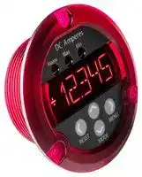
Illustrative purposes only

DMR30-DCV1-1-DC4-R-C
DC SHUNT VOLTMETER, 5-DIGIT, 11.4MM, 32V
⚠️ Reference pricing provided. In case of supply shortages, we will connect you with our trusted procurement partners to ensure your project's continuity.
- Manufacturer: MURATA POWER SOLUTIONS
- Product type: Digital Panel Meters
- SVHC: No SVHC (04-Feb-2026)
- Meter Range: ± 200mV / ± 2V / ± 20V
- Digit Height: 11.4mm
- Product Range: DMR30-DCV1 Series
- Meter Function: DC Voltage
- Panel Cutout Width: -
- Supply Voltage Max: 32VDC
- Supply Voltage Min: 9VDC
- Panel Cutout Height: -
- No. of Digits / Alpha: 5
- Operating Temperature Max: 50°C
- Operating Temperature Min: 0°C
| Delivery and price | |
|---|---|
| Units per pack | 1 |
| Price | 96.38 € |
| Current stock | 10+ |
| Lead time | 30 days |
Datasheet

## muRata |Ps Murata Power Solutions

## **DMR30-DCV1 Series**

## Precision DC Voltmeter

## **PRODUCT OVERVIEW**

The DMR30-DCV1 digital panel meter performs precision DC voltage measurements, with selectable ranges of +/-200mV, +/-2V, and +/-20V. This meter features a highly visible, 0.45" (11.4mm) high, 5 character+sign alphanumeric LED display which can provide up to 4.5 digits of measurement resolution. Configuration is made easy by a contactless touch-sensor frontpanel user interface, eliminating the need for jumpers, potentiometers, or DIP switches. The meter is powered from an external 9-32VDC supply and typically requires only 40mA when operated at 12V. The measurement inputs provide +/-48V of common mode input range, simplifying its use in a wide range of applications. An isolated solid-state relay can be set to close at user-defined trip-points, providing external signaling capability. The meter features a rugged polycarbonate housing that is mountable in a round hole using the supplied nut and gasket, or by using 3 #4-40 (M3) screws. The DMR30-DCV1's features make it ideal for use in laboratory instrumentation, factory automation, and other applications requiring precise DC voltage monitoring.

## **Features**

- Selectable +/-200mV, 2V, 20V input ranges

- Bright 0.45" (11.4mm) LED display visible up to 20 feet (6 meters)

- Long-life contactless touch-sensor controls

- Peak and valley measurement modes

- Digital filter option for measurements in noisy environments

- Solid-state alarm relay with programmable -

- trip point and hysteresis

- Convenient mounting options

- Operates from 9 to 32 VDC

- Low current consumption; 40mA typical at 12VDC

- Two year warranty

|**ORDERING INFORMATION:**<br>~~Waa~~<br>~~aeeee~~|**ORDERING INFORMATION:**<br>~~Waa~~<br>~~aeeee~~|
|---|---|
|MODEL NUMBER<br>~~Waa~~|DESCRIPTION<br>~~Waa~~<br>~~ae eee~~|
|DMR30-DCV1-1-DC4-R-C|DC voltmeter, alarm output, red display|
|DMR30-DCV1-1-DC4-G-C*|DC voltmeter, alarm output, green display|
|DMR30-DCV1-1-DC4-B-C*|DC voltmeter, alarm output, blue display|
|*Contact factory for availability.||


*Contact factory for availability.

**==> picture [357 x 228] intentionally omitted <==**

**----- Start of picture text -----**<br>
ee SIMPLIFIED BLOCK DIAGRAM<br>DMR30-DCV<br>ALPHANUMERIC DISPLAY<br>VOLTMETER<br>AND ANNUNCIATORS<br>INPUTS<br>ALARM MAX MIN mV<br>+VIN (5)<br>‘S| ADC @ee0e<br>-VIN (6)<br>—<br>TOUCH SENSOR KEYPAD<br>MICROCONTROLLER<br>RESET MENU<br>— O<br>MODE<br>RELAY<br>POWER SUPPLY Solid State OUTPUTS<br>INPUTS Relay<br>PTC Fuse (1) RELAYB<br>+VS (3) 3.3V<br>DC-DC -3.3V (2) RELAYA<br>-VS (4)<br>Omers l Be t s<br>**----- End of picture text -----**<br>


For full details go to **www.murata-ps.com/rohs**

**www.murata-ps.com/support.html**

**DMR30-DCV1.A01   Page 1 of 11**

**DMR30-DCV1 Series**

Precision DC Voltmeter

## Murata Power Solutions

|**MEASUREMENT PERFORMANCE**<br>~~a~~|**MIN.**<br>~~a~~|**TYP.**<br>~~a~~|**MAX.**<br>~~a~~|**UNITS**<br>~~a~~|
|---|---|---|---|---|
|Measurement ranges<br>~~a~~|±200mVDC; ±2VDC; ±20VDC<br>~~a~~|||~~a~~|
|Accuracy (Measured using 4 ½ digit display formats)||0.05|0.2|% Full-Scale|
|Temperature Stability||0.005||%Full-Scale/°C|
|Input Impedance||1||MΩ|
|Common Mode Rejection Ratio (DC)||100||dB|
|Absolute Maximum input voltage (+VIN to–VIN)|-40||+40|V|
|Absolute Maximum input voltage (either +VIN or–VIN  to–VS)|-48||48|V|


|**POWER SUPPLY CHARACTERISTICS.**<br>~~a~~|**Min.**<br>~~a~~|**Typ.**<br>~~a~~|**Max.**<br>~~a~~|**Units**<br>~~a~~|
|---|---|---|---|---|
|Operating Supply Voltage;<br>~~a~~|9<br>~~a~~|~~a~~|32<br>~~a~~|VDC<br>~~a~~|
|Absolute Maximum Supply Voltage|-1||34|VDC|
|Operating Supply Current<br>12V  operation<br>24V operation|-|40<br>25|-|mA|
|**USER INTERFACE**<br>~~|~~|||||
|Display Type and Size<br>~~|~~|5 Digit Alphanumeric LED, 11.4mm (0.45in) Height<br>4 LED Annunciators (‘Alarm’,‘Max’,‘Min’,‘mV’)<br>~~|~~||||
|User Controls|Four capacitive touch sensors<br><UP> <DOWN> <LEFT> <RIGHT>||||
|Display Modes|Normal, Max Voltage, Min Voltage||||
|Over-range Indication|Flashing Value||||
|Display Update Rate|2.5 updates/sec.||||
|Decimal Point Selection|Automatically Set||||
|Main Menu Password|<RIGHT> <UP> <RIGHT> <UP> <RIGHT><br>~~eeeeee~~||||
|**RELAY OUTPUT**<br>~~ee~~|**Min.**<br>~~ee~~|**Typ.**<br>~~ee~~<br>~~eee~~|**Max.**<br>~~ee~~<br>~~eee~~|**Units**<br>~~ee~~<br>~~eee~~|
|‘Off’-state voltage (measured across RELAYA to RELAYB) terminals<br>~~ee~~|-40<br>~~ee~~|~~ee~~<br>~~eee ~~|+40<br>~~ee~~<br> ~~eee~~|V<br>~~ee~~<br>~~eee~~|
|‘On’-state current|-250||+250|mA|
|‘On’state resistance||1||Ω|
|**TERMINAL BLOCKS  (TB1, TB2, TB3)**|||||
|**TERMINAL BLOCKS  (TB1, TB2, TB3)**<br>Wire Size|14-24 AWG||||
|Insulation Strip Length|6mm (0.24 in.)||||
|Screw Tightening Torque|0.4 N-m (3.5 lb-in)<br>~~eee~~<br>~~eee~~<br>~~|~~||||
|**PHYSICAL/ENVIRONMENTAL**<br>~~ee~~|**Min.**<br>~~ee~~|**Typ.**<br>~~ee~~<br>~~eee~~|**Max.**<br>~~ee~~<br>~~eee~~|**Units**<br>~~ee~~<br>~~|~~|
|OperatingTemperature<br>~~ee~~|0<br>~~ee~~|~~ee~~<br>~~eee~~|+50<br>~~ee~~<br>~~eee~~|⁰C<br>~~ee~~<br>~~|~~|
|Storage Temperature|-40||+75|⁰C|
|Humidity (non-condensing)|0||85|%|
|Dimensions|See Mechanical Specifications Drawing||||
|Weight  (including mounting nut and gasket)|64g (2.2 oz)||||


**www.murata-ps.com/support.html**

**DMR30-DCV1.A01   Page 2 of 11**

**DMR30-DCV1 Series** Precision DC Voltmeter

## sunRataMurata Power Solutions| Ps

## ~~rrr~~ **OPERATION:**

## Measurement Type and Capabilities

DMR30-DCV1 series digital voltmeters employ a precision ADC and a low-power microcontroller to measure and display DC voltage.   These meters provide user-selectable measurement ranges of +/-200mVC, 2VDC, and 20VDC, with a 1  MΩ input impedance.  The meter’s measurement system supports a common-mode input voltage range of up to +/-48V in relation to the power supply return (-VS connector), simplifying applications where the meter’s power supply return is not suitable for a –VIN reference.

The number of display digits is also user-selectable to support applications where additional digits may be a distraction.  A digital filter option with three settings (OFF, FAST, SLOW) is offered to help optimize for operations in electrically noisy environments.

## ~~T~~ **FRONT PANEL & FRONT PANEL LAYOUT AND FUNCTION**

1. **Annunciator LEDs:** This cluster of 3 LEDs indicate various meter states, such alarm status,  measurement mode, and

1 unit. 2. **Display:** This is a 5-character + sign alphanumeric LED display is used to indicate measurements, informational

2 prompts, and meter setup parameter values. 3. **Touch-Sensor Control Buttons:** Four capacitive touchsensors are provided to support meter control and configuration. These four buttons will be referred to in this document as <UP>, <DOWN>, <LEFT>, and <RIGHT>

3 reflecting their printed arrow directions.

Oo

DMR30-DCV1 meters defaults to  ‘normal mode’ in which the meter displays the current value of the measured voltage. If the measured input value falls outside of the meter’s acceptable measurement range, either over-range or under-range, the display will flash.While the meter’s alarm functions are enabled, the ALARM annunciator is lit whenever the alarm relay is activated (closed).

## **Alternate Measurement Modes (MAX, MIN)**

In addition to displaying the current value of the measurement (normal mode), the meter can also display historical high and low values. To perform these operations, the meter offers a number of alternate measurement modes:

1. In MAX mode, the meter displays the highest value which has been measured since the last time the user pressed the <LEFT> button (RESET).  MAX mode is active when the MAX LED is illuminated.

2. In MIN mode, the meter displays the lowest value which has been measured since the last time the user pressed <LEFT> button (RESET). MIN mode is active when the MIN LED is illuminated.

These alternate measurement modes may be selected by repeatedly pressing the <DOWN> button until the desired mode LED is illuminated.  The alternate modes may be disabled by repeatedly pressing the <DOWN> button until all mode LEDs are off and the meter is returned to normal operating in which it will display the current measurement.

Access to the alternate measurement modes may be disabled by setting the MODES setting to OFF using the configuration menu.  If alternate modes are disabled, then pressing either the <DOWN> or <LEFT> buttons will result in an ‘ERROR’ message being briefly displayed before resuming normal operation.

**www.murata-ps.com/support.html**

**DMR30-DCV1.A01   Page 3 of 11**

**DMR30-DCV1 Series** Precision DC Voltmeter

## Murata Power Solutions

## ~~CO~~ **ELECTRICAL CONNECTIONS:**

|Screwterminal Location:|Terminal #|Name|Function|
|---|---|---|---|
|1<br>RELAYB<br>Alarm Relay outputs<br>2<br>RELAYA<br>3<br>+VS<br>Power supply terminals(9VDC -<br>32VDC)<br>4<br>-VS<br>5<br>+VIN<br>Measurement Input terminals<br>6<br>-VIN<br>EE|1|RELAYB|Alarm Relay outputs|
||2|RELAYA||
||3|+VS|Power supply terminals(9VDC -<br>32VDC)|
||4|-VS||
||5|+VIN|Measurement Input terminals|
||6|-VIN||
|Note: It is important to tighten all screw-terminals to their torque specification of 4.5 lb.-in  (0.51Nm). Proper tightening will help ensure<br>reliable operation.  Applications subject to vibration should use stranded wire.||||


## **Alarm Relay Connections**

The DMR30-DCV1 provides a solid-state relay output that ‘closes’ when an alarm condition is detected.  This circuit is electrically isolated from the meter’s measurement circuitry and the power supply inputs, providing a high degree of applications flexibility – similar to that of a mechanically contacting relay.  Because the output relay is a semiconductor device, caution should be exercised when driving loads which have high inrush currents such as incandescent lamps or inductive loads such as electromechanical relays, as the associated current and voltage spikes may damage the meter.  When used to drive an inductive load, a ‘flyback’ diode should be connected across the relay coil (ensuring correct polarity so that it will not forward conduct under normal use) to suppress high transient voltages that may damage the DMR30-DCV1, as shown in the following illustration:

**==> picture [196 x 73] intentionally omitted <==**

**----- Start of picture text -----**<br>
DC ELECTROMECHANICAL<br>SUPPLY RELAY<br>DMR30-DCV1<br>RELAYA ) ‘ ‘FLYBACK’<br>RELAYB DIODE Note that the diode must be<br>connected so that it does not<br>eH<br>forward conduct when the<br>relay is turned on.<br>**----- End of picture text -----**<br>


## **Notes:** AN

- The alarm relay circuit’s isolation is not intended for use as a safety isolation barrier. The maximum voltage  between the alarm relay terminals (RELAYA or RELAYB) and the input terminals (+VIN, -VIN) or power supply terminals (+VS, -VS) must be limited to +/-48VDC. The alarm relay is intended to provide an informational signal of over-temperature/under-temperature conditions; for example driving a piezoelectric siren or LED lamp to signal the condition.

- The DMR30’s alarm output relay must not be used in the control loop of any type of system where it either directly or indirectly signals that a heating or cooling element is to be turned on or off, or used as a safety limit switch.

## **Power Supply Connections**

The meter is powered through the +VS and –VS terminals and requires a DC power supply which may range from 9VDC to 32VDC.  This supply is electrically isolated from the meter’s measurement electronics,  so that the meter’s negative or return measurement input terminal (-VIN) does not need to be connected to the meter’s power return terminal (-VS), and may vary as much as +/-48V from this connection.  Please note that the meter’s isolation barrier is intended only to simplify measurements, and not for safety purposes – the maximum voltage  between the power supply terminals (+VS or –VS) and the measurement input terminals (+VIN, -VIN) must be limited to +/-48VDC.

The DMR30 series of meters incorporates protection against momentary applications of both overvoltage and reverse polarity to the power supply(+VS, -VS) terminals.   Depending on regulatory and application requirements it may also be necessary for the user to add external fusing.

## **Measurement Inputs**

Voltage to be measured by the DMR30-DCV1 is applied to the +VIN and -VIN connections (terminals 5 and 6).  Unlike many panel meters, the DMR30-DCV1 measurement inputs are electrically isolated from the power supply terminals, which allows for fully differential measurements over a common-mode range of +/-48V with respect to the power supply terminals +VS or -VS.

**www.murata-ps.com/support.html**

**DMR30-DCV1.A01   Page 4 of 11**

**DMR30-DCV1 Series**

Precision DC Voltmeter

## Murata Power Solutions

## **CONNECTION EXAMPLE**

The following shows a DMR30-DCV1 application where the alarm relay is used to drive a piezoelectric siren. In this example, a 12VDC power supply is connected to the +VS and –VS terminals, the voltage to be measured is connected to the +VIN and –VIN inputs, and the alarm relay is used to control a piezoelectric siren, also powered from the +12VDC power supply.

**==> picture [159 x 152] intentionally omitted <==**

**----- Start of picture text -----**<br>
DMR30-DCV1<br>2<br>Ze 2<br>NE)<br>1 G<br>Note: The voltage between point; A and<br>point B must be within +/-48V<br>**----- End of picture text -----**<br>


## **METER CONFIGURATION** Configuration Menu

The DMR30 family incorporates an interactive menu system to support meter configuration. This system eliminates the need for jumpers, dipswitches or trim-pots and also allows the meter be easily configured after it has been installed in an application.

## **Entering and Navigating the Menu System**

The DMR30’s user configuration system is structured as a main menu from which individual configuration options are selected for editing.   When in measurement mode, pressing the **<RIGHT>** button will cause the meter to enter the main menu, and display the first main menu entry - RANGE.  To prevent accidental changes to the meter’s configuration, entry to the main menu may optionally be password protected.  If the password protection option is enabled (See MLOCK entry on pg.8 for details), then the user will be prompted to enter a series of five button-touches to enter the main menu.

Once in the main menu, the meter will display the currently selected entry. The **<UP>** and **<DOWN>** buttons may be used to change the active selection.

**www.murata-ps.com/support.html**

**DMR30-DCV1.A01   Page 5 of 11**

**DMR30-DCV1 Series** Precision DC Voltmeter

Murata Power Solutions

## ~~aaa~~ **MENU CONFIGURATION**

## MENU DIAGRAM: DMR30-DCV1

**==> picture [532 x 348] intentionally omitted <==**

**----- Start of picture text -----**<br>
Mlock=ON<br>Passcode<br>Menu<br>Mlock=OFF<br>Range<br>D Fmt<br>||<br>Brite<br>|<br>Filt<br>|<br>Alarm<br>|<br>Aset<br>|<br>Ahyst<br>|<br>Atest<br>|<br>Modes<br>|<br>Mlock 100%<br>| [|<br>Frst 90%<br>|<br>Main Menu LoLim 20 V<br>° |<br>Confirm ON Numeric  HiLim 30% 2 V<br>Yes/No OFF Entry OFF 20% 200mV<br>Co) Reset || Enable  CO Enter Alarm  | Choose Alarm  |oe SS Brightness  +/- Full-scale ||<br>To Factory Min/Max  Hysteresis Enabled/Type Selection Voltage Range<br>Defaults Modes Value<br>Bolded Slow 99999<br>Items are ON A-ON Numeric  & Fast & 9999<br>Factory<br>Defaults Seo OFF A-OFF ) Entry aee OFF e 999 e<br>Password Interactive  Enter Alarm Select Digital  Select Display<br>Protect Alarm Relay Set-point Data Filter Digits<br>Settings Test Value<br>**----- End of picture text -----**<br>


**USING THE MENU**

When the meter is displaying a main menu item, pressing the **<RIGHT>** button will display the submenu associated with that menu item.  For example, if **BRITE** is the currently selected main menu item, then pushing the **<RIGHT>** button will display the brightness submenu, and display the currently selected brightness level (100% being the default).

Exiting the main menu and return to measurement mode may be done in two ways. The first is to press the **<LEFT>** button.  The second method is to simply do nothing – if the meter is in the menu system and no button presses are registered for approximately 60 seconds,  the meter will automatically return to measurement mode.  The **<LEFT>** arrow also may be used to return from a submenu back to the main menu.

**www.murata-ps.com/support.html**

**DMR30-DCV1.A01   Page 6 of 11**

**DMR30-DCV1 Series** Precision DC Voltmeter

Murata Power Solutions

## ~~ee~~ **USING THE MENU**

## **The Main Menu**

The **DMR30-DCV1** has the following MAIN MENU configuration options:

• **RANGE** – This submenu is used to select the meter’s measurement range.  Available options may be scrolled through using the **<UP>** and **<DOWN>** buttons. When the desired **Range** setting is displayed, pressing the **<RIGHT>** button will update the **Range** option to the displayed value and return to the main menu, while pressing the **<LEFT>** button will return to the **MAIN MENU** without updating the value. • The **DMR30-DCV1** supports the following range options:

|**Menu Option **|**Range**|
|---|---|
|20V|+/-20 VDC input range|
|2V|+/-2 VDC input range|
|200mV|+/-200 mV input range– ‘mV’annunciator illuminated in this range|


## **USING THE MENU**

• **D FMT** This submenu is used to select the number of digits used to display the measurement.  The available options are **999, 9999, and 99999** . The **<UP>** and **<DOWN>** buttons are used to scroll through these options.  When the desired setting is displayed, pressing the **<RIGHT>** button will update the **D FMT** option to the displayed value and return to the main menu, while pressing the **<LEFT>** button will return to the main menu  without updating the option value.

• **BRITE** – This submenu is used to adjust the brightness of the meter’s display.  By using the **<UP>** and **<DOWN>** buttons the display can be adjusted from 20% to 100% intensity in 10% increments.  To aid in selecting an appropriate brightness level, the meter’s brightness is adjusted in real time as the various menu options are displayed. Once a desired brightness setting has been found, this option may be updated by pressing the **<RIGHT>** button, which updates the option value and returns to the main menu. Pressing the **<LEFT>** button will return to the main menu with the brightness setting being unchanged.

• **FILT** – This option selects the degree of digital filtering that is applied to the measured signal.  The available options are  (1) **OFF** -  in which no filtering is used, (2) **FAST** – in which a small amount of filtering is applied to the signal, and (3) **SLOW** – in which a larger amount of filtering is applied to the signal.  The **<UP>** and **<DOWN>** buttons are used to scroll through the filter options. Pressing the **<RIGHT>** button will update the option to the displayed value and return to the main menu. Pressing the **<LEFT>** button will return to the main menu without updating the option.

• **ALARM** – This submenu controls the operation of the alarm relay output. This submenu  has three available options; (1) **OFF** , where the alarm output is disabled and always off, (2) **HILIM** , where the alarm relay is turned on when the measured voltage is greater than the alarm set-point value, and (3) **LOLIM** , where the alarm output is turned on when the measured voltage is less than the alarm set-point value.  The **<UP>** and **<DOWN>** buttons may be used to scroll through these options. To update the setting to the selected option and return to the **MAIN MENU** , press the **<RIGHT>** button. To return to the **MAIN MENU** without updating the setting, press the **<LEFT>** button.

• **ASET** – This submenu is a numeric entry field used to set the alarm set-point value.  On entry to this submenu, the current value of the alarm set-point is displayed and may be edited.   Upon entering this option, the display will show the current alarm value, and set a blinking cursor at the sign character. The <UP> and <DOWN> buttons are used to set the sign or to increment/decrement the currently selected digit. The <RIGHT> button selects the next digit, or if at the rightmost digit, accepts the displayed value and returns to the MAIN MENU.  The <LEFT> button can be used to move the cursor left, or if the cursor is set to the sign position, exits the submenu without changing the current alarm set-point value.

• **AHYST** – This setting controls the alarm hysteresis value.  When the alarm is set to HILIM mode,  the hysteresis is subtracted from the alarm set-point to get a ‘turn-off’ threshold below which the alarm relay is opened.   Similarly (but opposite), when the alarm is set to LOLIM mode, the hysteresis value is added to the set-point to provide a turn-off threshold above which the alarm relay is opened. The process for setting the alarm hysteresis value is similar to setting the alarm set-point value, with the buttons providing identical functionality.  Unlike **ASET** values, however, **AHYST** values may only be set to values greater than or equal to zero.

**www.murata-ps.com/support.html**

**DMR30-DCV1.A01   Page 7 of 11**

**DMR30-DCV1 Series** Precision DC Voltmeter

Murata Power Solutions

## **USING THE MENU**

• **ATEST** – This submenu allows the user to interactively test the  alarm relay circuit without needing to adjust either the alarm set-point or the signal applied to the meter inputs.  On entering this menu option, the **<UP>** button will turn the alarm relay **ON** , while the **<DOWN>** button will turn the alarm relay **OFF** .  Either the **<LEFT>** or **<RIGHT>** buttons will exit this submenu, set the alarm relay to the **OFF** condition, and return to the **MAIN MENU** . Note that the alarm relay is set to the **OFF state** when the meter is in the menu system regardless of either the meter input signal alarm settings.

• **MODES** – This submenu is used to enable or disable the alternate measurement modes (see Alternate Measurement Modes, pg. 3).  When the **Modes** option is set to **ON** , MIN and MAX reading modes for the meter will be available from the front panel.  When this option is set to **OFF** attempting to set the meter to MIN or MAX mode will result in an **ERROR** message being displayed.

• **MLOCK** – This submenu is used to enable or disable password protection for the **MAIN MENU** .  If **MLOCK** option is set to **ON** , pressing the <RIGHT> button in operating mode results in a flashing cursor, prompting for the entry of a button-sequence password.  The following password sequence must then be entered to access the MAIN MENU:

## **<RIGHT> <UP> <RIGHT> <UP> <RIGHT>**

If the **MLOCK** option is set to **OFF** , pressing the **<RIGHT>** button in operating mode will immediately enter the **MAIN MENU** .  Note that the password is set at the factory and is not user-modifiable.

• **FRST** – This submenu resets the meter configuration to the factory default values. To reset the meter, scroll to the **YES** option using the **<UP>** button and then press the **<RIGHT>** button to confirm. To quit this submenu without resetting the meter, press the **<LEFT>** button.

|DMR30-DCV1 FACTORY DEFAULT CONFIGURATION<br>~~|~~|DMR30-DCV1 FACTORY DEFAULT CONFIGURATION<br>~~|~~|
|---|---|
|MAIN MENU Item<br>~~|~~|Default Value<br>~~|~~|
|RANGE|20 V|
|D FMT|99999|
|BRITE|100%|
|FILT|OFF|
|ALARM|OFF|
|ASET|0|
|AHYST|0.0|
|MODES|ON|
|MLOCK|OFF|


**www.murata-ps.com/support.html**

**DMR30-DCV1.A01   Page 8 of 11**

**DMR30-DCV1 Series**

Precision DC Voltmeter

Murata Power Solutions

## **TECHNICAL NOTES**

## **1. Calibration**

The DMR30-DCV1 is calibrated at the factory at manufacture. There are no user or field-adjustable calibration features.

## **2. Wiring:**

Power supply and input  wiring must be rated for the electrical and environmental conditions under which the meter will be operated. They must also comply with any regulatory or application-mandated requirements pertaining to the user’s installation.

The terminal blocks can accommodate wire gauges ranging from #14 to #24 AWG. Wiring Insulation should be stripped to 6mm (0.24”).  All wires must be inserted into the terminal block openings such that the screw terminal does not pinch any insulation. It is important to tighten all screw-terminals to their torque specification of 4.5 lbf-in  (0.51Nm). Proper tightening will help ensure reliable operation.  Applications subject to vibration should use stranded wire.  After final assembly, inspect all terminal block connections for shorts between adjacent conductors; this step is especially important when using stranded wire.

## **3. Protection and Fusing:**

DMR30 meters’ power supply leads (+VS, -VS) are protected against momentary overvoltage and reverse polarity conditions. Input terminals +VIN and -VIN are protected against noise and brief voltage transients.  Protection, however, is not provided against sustained conditions exceeding the limits listed in in the Performance & Functional Specifications Table. External fusing must be supplied by the user in accordance to applicable safety and regulatory requirements for the system in which the DMR30 is installed.

## **4. Noisy Power Supplies**

Some power supplies contain high-frequency switching devices that may conduct and/or radiate significant noise onto the low-level signal developed across the measurement inputs. Even though the DMR30  incorporates built-in input filtering, some portion of this noise may be amplified and subsequently measured by its sensitive input circuitry.  Limiting runs of wire to <3m is strongly recommended.  Also, in systems with noisy power supplies, connecting an external, non-polarized capacitor across the +VS and -VS inputs can help reduce measurement errors. In certain situations, the use of twisted pair or shield wiring may be required.

## **5. Self-Diagnostics**

On power-on the meter performs a self-test and checks the integrity of calibration and configuration data stored in internal non-volatile memory. If the factory calibration data has been corrupted, the meter will display ‘NoCal’ on power-on and approximately once a minute thereafter to indicate that the meter is relying on default calibration factors and that displayed measurements may have more than the datasheet-specified amount of error.  If the meter detects that its configuration data has been corrupted, it will display ‘NoCFG’ and attempt to reset itself to the default factory configuration.

**www.murata-ps.com/support.html**

**DMR30-DCV1.A01   Page 9 of 11**

## **DMR30-DCV1 Series**

## Murata Power Solutionss

## Precision DC Voltmeter

**==> picture [527 x 400] intentionally omitted <==**

**----- Start of picture text -----**<br>
PANEL INSTALLATION<br>PANEL CUTOUT OPTIONS<br>Option 1  Option 2 Option 3<br>For mounting with single 50mm nut  For mounting with 3x 64.5mmscrews  For mounting with 3x 62mm screws<br>7 y— 3x D.144-.156<br>a! (27.94 ] / yp 3x D.144-.156<br>1.100 / 2.060 MIN [26.86 ] e /<br>| vA lL 2.250 MAX ) 1.087 / / / b2250wax<br>{ / \ | (3228 ] yy | \\ ba} (3099 ] VY ~S<br>| \ (939 ] i { \ \ 1.829 : {\/ | \ \<br>\ t } PANEL ‘ | [| \ |<br>\ J | (1/2" MAX THICK) | \ teI \ Lh} | 7 \\ +| i{<br>/t Ja ¢ PANEL(7/8" MAX THICK) 7 { \— PANEL(7/8" MAX<br>2.020 MIN (64.52 ] / . / €<br>2.100 MAX O2540B.0. __/ Le (55.87 | {61.98 | /<br>IT IS RECOMMENDED THAT THIS HOLE REF 2.200 2.440REF BC. ‘__/ —_— [53802.114 |<br>BE AS SMALL AS POSSIBLE WITHIN THE RANGE<br>SPECIFIED, ESPECIALLY IF MULTIPLE METERS ARE THIS OPTION REQUIRES THREE<br>MOUNTED AND ALIGNED SIDE BY SIDE HOLES TO BE OPENED IN HOUSING THIS OPTION REQUIRES THREE<br>HOLES TO BE OPENED IN HOUSING<br>Housing Flange Modifications for Mounting Options 1 and 2<br>1) .027 EMBOSSMENTS<br>LH<br>OACa<——_,oy, ~ 7 ‘<br>|f/f7“/o000\L[OO00\%\\ \<br>[ !1 u\ O<br>1 '<br>(\t|<br>**----- End of picture text -----**<br>


**www.murata-ps.com/support.html**

**DMR30-DCV1.A01   Page 10 of 11**

**DMR30-DCV1 Series** Precision DC Voltmeter

## Murata Power Solutions

## MECHANICAL SPECIFICATIONS

**This product is subject to the following operating requirements and the Life and Safety Critical Application Sales Policy: Refer to:https://www.murata-ps.com/requirements/**

Murata Power Solutions, Inc. 129 Flanders Rd. Westborough, Ma  01581, USA. ISO 9001  and 14001  REGISTERED

Murata Power Solutions, Inc. makes no representation that the use of its products in the circuits described herein, or the use of other technical information contained herein, will not infringe upon existing or future patent rights. The descriptions contained herein do not imply the granting of licenses to make, use, or sell equipment constructed in accordance therewith. Specifications are subject to change without notice. _**© 2019 Murata Power Solutions, Inc..**_

**www.murata-ps.com/support.html**

**DMR30-DCV1.A01   Page 11 of 11**
Updated at June 9, 2026
About Novapart
Novapart is a B2B electronic component broker specialising in stock shortages and cost reduction. We source hard-to-find parts and identify compliant alternatives across a catalogue of 410,000+ components from 500+ manufacturers.
Learn more →Stock Shortage Specialist
When a component is unavailable, discontinued or has an unacceptable lead time, we tap into our network of vetted European and Asian distributors to source what you need — without compromising on quality or traceability.
Request a quote →Compliant Alternatives
We identify pin-to-pin, electrically equivalent substitutes that meet the same certifications (RoHS, AEC-Q100, REACH) as your original specification — validated against datasheets, not just part numbers. Often at a lower cost.
BOM Analysis service →