


DLE45PS48
LED Driver, Constant Voltage & Current, 48 W, 48 VDC, 1 A, Constant Current, Constant Voltage, 90 V
- Manufacturer: XP POWER
- Product type: AC / DC LED Power Supplies
- Product Range: DLE
- Output Current: 1A
- LED Driver Mode: Constant Current, Constant Voltage
- Output Power Max: 48W
- Input Voltage Max: 305V
- Input Voltage Min: 90V
- Output Voltage Max: 48VDC
| Delivery and price | |
|---|---|
| Units per pack | 1 |
| Price | 18.81 € |
| Current stock | 10+ |
| Lead time | 30 days |
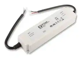
## 45/60 Watts

## • AC Input LED Driver **xxx Series**

## • AC Input LED Driver

- Constant Voltage/Constant Current Operation

- Constant Current Dimming Versions

- High Efficiency

- Water Proof to IP67

- Class 2

- 3 Year Warranty

The DLE series of AC input LED drivers incorporate universal input with active power factor correction in a two power stage design, eliminating flicker while providing a high efficiency solution. Designed as a class II isolation product, without the need for a safety earth, DLE series LED drivers are also approved as a class 2 limited power source, making them suitable for a wide range of applications. Dimmable constant current versions are available with the facility for PWM, voltage and resistance programming.

**Dimensions:**

## **DLE45/60:**

6.73 x 1.78 x 1.27” (164.1 x 45.3 x 32.5 mm)

|Output Power<br>~~ee~~|Output Voltage<br>~~ee~~|Output Current|Output Voltage Range in<br>Constant Current Mode|OVP Range<br>~~ee~~|Efficiency(1)<br>~~ee~~|Model Number|
|---|---|---|---|---|---|---|
|45 W<br>~~ee~~|24 V<br>~~ee~~|1850 mA|16 - 24 V|26.4-31.2 V<br>~~ee~~|85.0%<br>~~ee~~|DLE45PS24|
|45 W<br>~~ee~~<br>~~a~~|36 V<br>~~ee~~|1250 mA|24 - 36 V|39.6-46.8 V<br>~~ee ~~<br>~~ee~~|86.0%<br> ~~ee~~<br>~~ee~~|DLE45PS36<br>~~ee~~|
|48 W<br>~~a~~|48 V|1000 mA|34 - 48 V|52.8-62.4 V<br>~~ee~~|87.0%<br>~~ee~~|DLE45PS48<br>~~ee~~|
|40 W<br>~~a~~<br>~~a~~|57 V|700 mA|40 - 57 V|62.9-70.0 V<br>~~ee~~<br>~~GO~~|87.0%<br>~~ee~~<br>~~GO~~|DLE45PS57<br>~~ee~~|
|50 W<br>~~GC~~<br>~~a~~|12 V<br>~~GC~~|4200 mA<br>~~GC~~|9 - 12 V<br>~~GC~~|13.2-15.6 V<br>~~GC~~<br>~~GO~~|86.0%<br>~~GC~~<br>~~GO~~<br>~~ee~~|DLE60PS12<br>~~GC~~|
|60 W<br>~~a~~|24 V|2500 mA|16 - 24 V|26.4-31.2 V<br>~~GO~~<br>~~ee~~|86.0%<br>~~GO~~<br>~~ee~~<br>~~ee~~|DLE60PS24<br>~~ee~~|
|60 W<br>~~Pe~~|36 V<br>~~Pe~~|1650 mA<br>~~GC~~|24 - 36 V<br>~~GC~~|39.6-46.8 V<br>~~GO~~|87.0%<br>~~ee~~<br>~~GO~~|DLE60PS36|
|60 W<br>~~Pe~~<br>~~Pe~~|48 V<br>~~Pe~~<br>~~Pe~~|1250 mA<br>~~GC~~<br>~~Pe~~|34 - 48 V<br>~~GC~~<br>~~Pe~~|52.8-62.4 V<br>~~GO~~<br>~~Pe~~|88.0%<br>~~GO~~<br>~~ee~~|DLE60PS48<br>~~ee~~|
|60 W<br>~~Pe~~<br>~~Pe~~|57 V<br>~~Pe~~<br>~~Pe~~|1050 mA<br>~~GC~~<br>~~Pe~~|40 - 57 V<br>~~GC~~<br>~~Pe~~|62.9-70.0 V<br>~~GO~~<br>~~Pe~~|88.0%<br>~~GO~~<br>~~ee~~|DLE60PS57<br>~~ee~~|


|Output Power|Output Voltage|Output Current|Output Voltage Range in<br>Constant Current Mode|OVP Range|Efficiency(1)|Model Number|
|---|---|---|---|---|---|---|
|45 W<br>~~a~~<br>~~a~~|24 V<br>~~eG~~|1850 mA<br>~~eG ~~|16 - 24 V<br> ~~GCC~~|26.4-31.2 V<br>~~GCC~~<br>~~ee~~|85.0%<br>~~GCC~~<br>~~ee~~|DLE45PS1850-AD<br>~~GCC~~<br>~~ee~~|
|45 W<br>~~a~~<br>~~DR~~|36 V<br>~~GG~~|1250 mA<br>~~GG~~|24 - 36 V<br>~~GG~~|39.6-46.8 V<br>~~ee~~<br>~~GG~~<br>~~GO~~|86.0%<br>~~ee~~<br>~~GG~~<br>~~GO~~|DLE45PS1250-AD<br>~~ee~~<br>~~GG~~|
|48 W<br>~~a~~<br>~~DR~~|48 V<br>~~GG~~|1000 mA<br>~~GG~~|34 - 48 V<br>~~GG~~|52.8-62.4 V<br>~~ee~~<br>~~GG~~<br>~~GO~~|87.0%<br>~~ee~~<br>~~GG~~<br>~~GO~~|DLE45PS1000-AD<br>~~ee~~<br>~~GG~~|
|40 W<br>~~DR ~~<br>~~es~~|57 V<br> ~~GG~~|700 mA<br>~~GG~~|40 - 57 V<br>~~GG~~|62.9-70.0 V<br>~~GG~~<br>~~GO~~<br>~~a~~|87.0%<br>~~GG~~<br>~~GO~~<br>~~ee~~|DLE45PS700-AD<br>~~GG~~|
|50 W<br>~~es~~|12 V|4200 mA|9 - 12 V|13.2-15.6 V<br>~~a~~|86.0%<br>~~ee~~|DLE60PS4200-AD|
|60 W<br>~~es~~<br>~~a~~|24 V|2500 mA|16 - 24 V|26.4-31.2 V<br>~~a~~<br>~~ee~~|86.0%<br>~~ee~~<br>~~ee~~|DLE60PS2500-AD<br>~~ee~~|
|60 W<br>~~a~~<br>~~DR~~<br>~~a~~|36 V<br>~~GG~~<br>|1650 mA<br>~~GG~~<br>|24 - 36 V<br>~~GG~~<br>|39.6-46.8 V<br>~~ee~~<br>~~GG~~<br>~~GO~~<br>|87.0%<br>~~ee~~<br>~~GG~~<br>~~GO~~<br>|DLE60PS1650-AD<br>~~ee~~<br>~~GG~~<br>|
|60 W<br>~~a~~<br>~~DR~~<br>~~a~~|48 V<br>~~GG~~<br>|1250 mA<br>~~GG~~<br>|34 - 48 V<br>~~GG~~<br>|52.8-62.4 V<br>~~ee~~<br>~~GG~~<br>~~GO~~<br><br>~~QC~~|88.0%<br>~~ee~~<br>~~GG~~<br>~~GO~~<br><br>~~QC~~|DLE60PS1250-AD<br>~~ee~~<br>~~GG~~<br>|
|60 W<br>~~DR ~~<br>~~a ~~|57 V<br> ~~GG~~<br> ~~eG~~|1050 mA<br>~~GG~~<br>~~eG~~|40 - 57 V<br>~~GG~~<br>~~eG~~|62.9-70.0 V<br>~~GG~~<br>~~GO~~<br>~~eG~~<br>~~QC~~|88.0%<br>~~GG~~<br>~~GO~~<br>~~eG~~<br>~~QC~~|DLE60PS1050-AD<br>~~GG~~<br>~~eG~~|


**www.xppower.com**

1

|Characteristic|Minimum|Typical|Maximum|Units|Notes & Conditions|
|---|---|---|---|---|---|
|Input Voltage - Operating|90||305|VAC|See derating curve|
|Input Frequency|47||63|Hz||
|Power Factor||>0.9|||Measured at 230 VAC, full load|
|Input Current||0.6||A|115 VAC|
|||0.3|||230 VAC|
|Inrush Current|||45|A|230 VAC cold start,+25ºC|
|Input Protection|Internal T1.0 A/250 V fuse fitted in line|||||


|Characteristic<br>~~po~~|Minimum<br>~~po~~|Typical<br>~~po~~|Maximum<br>~~po~~|Units<br>~~po~~|Notes & Conditions<br>~~po~~|
|---|---|---|---|---|---|
|Output Voltage<br>~~a ~~<br>~~a~~|12<br> ~~GG~~<br>|~~GG~~<br>~~DG~~<br>|57<br>~~GG~~<br>~~DG~~<br>|VDC<br>~~GG~~<br>~~DG~~<br>|See models and ratings table<br>~~GG~~<br>|
|Minimum Load<br>~~eG~~<br>~~a~~|~~eG~~<br>|~~eG~~<br>~~DG~~<br>|~~eG~~<br>~~DG~~<br>|~~eG~~<br>~~DG~~<br>|No minimum load required<br>~~eG~~<br>|
|Start Up Delay<br>~~a ~~|~~GC~~|~~DG~~<br>~~GC~~|1.5<br>~~DG~~<br>~~GC~~|s<br>~~DG~~<br>~~GC~~|Measured at 115 VAC<br>~~GC~~|
|Hold Up Time<br>~~GG~~|20<br>~~GG~~|~~GG~~|~~GG~~|ms<br>~~GG~~|~~GG~~|
|Line Regulation<br>~~a ~~<br>~~ee~~|~~GC~~|~~GC~~|±0.5<br>~~GC~~<br>~~—~~|%<br>~~GC~~<br>~~—~~|~~GC~~<br>~~—~~|
|Load Regulation<br>~~ee~~||±1|~~—~~|%<br>~~—~~|Constant voltage mode<br>~~—~~|
|||±5|~~—~~||Constant current mode<br>~~—~~|
|Turn On Overshoot<br>~~ee~~<br>~~a ~~<br>~~a~~|~~GC~~<br>~~es~~|~~GC~~<br>~~es~~|7<br>~~—~~<br>~~GC~~|%<br>~~—~~<br>~~GC~~|Constant voltage mode<br>~~—~~<br>~~GC~~|
|Transient Response<br>~~a~~|~~es~~|~~es~~|4|%|Deviation, recovery to within 1% in 10 ms for a 50%<br>load change|
|Ripple & Noise<br>~~a~~<br>~~a~~|~~es~~|~~es~~|200/250|mV pk-pk|≤24 V/>24 V. Measured using 12” twisted pair with 0.1 µF<br>and 47 µF capacitors in parallel at 20 MHz bandwidth, at 25 °C|
|Overvoltage Protection<br>~~a~~|||||See models and ratings table, recycle AC to Reset|
|Overload Protection<br>~~DD~~|95<br>~~DD~~|~~DD~~|105<br>~~DD~~|%<br>~~DD~~|Auto Recovery<br>~~DD~~|
|Short Circuit Protection<br>~~a ~~|~~GG~~|~~GG~~|~~GG~~|~~GG~~|Trip & restart (hiccup mode)<br>~~GG~~|
|Temperature Coefficient<br>~~GC~~|~~GC~~|0.04<br>~~GC~~|~~GC~~|%/˚C<br>~~GC~~|~~GC~~|


## **Constant Current Curve**

**==> picture [355 x 112] intentionally omitted <==**

**----- Start of picture text -----**<br>
Vo max<br>Load Regulation in<br>Constant Current Mode<br>Vo min<br>Trip & Restart Zone<br>0 10 20 30 40 50 60 70 80 90 100<br>Output Current  (%)<br>Output Voltage<br>**----- End of picture text -----**<br>


|Characteristic|Minimum|Typical|Maximum|Units|Notes & Conditions|
|---|---|---|---|---|---|
|Efficiency||87||%|See models and tables|
|Isolation: Input to Output|3750|||VAC||
|Switching Frequency||100||kHz||
|Mean Time Between Failure||>200||kHrs|MIL-HDBK-217F at 25 °C GB|
|Weight||0.9 (410)||lb (kg)||


**www.xppower.com**

2

**==> picture [521 x 101] intentionally omitted <==**

**----- Start of picture text -----**<br>
|||||||
|---|---|---|---|---|---|
|Characteristic|Minimum|Typical|Maximum|Units|Notes & Conditions|
|Operating Temperature|-20|+50|°C|See derating curve|
|Operating Humidity|20|90|%|RH, non-condensing|
|Storage Temperature|-40|+80|°C|Some specification parameters maybe exceeded|
|until after 20 minutes warm up period.|
|Operating Altitude|3000|m|
|30 g pk, half sine, 6 axes EN60068-2-27, -2-47|
|Shock|& MIL-STD-810F 514.5 cat 4|
|10-500 Hz, 2 g, 10 mins/cycle, 6 cycles in each|
|Vibration|of axes|

**----- End of picture text -----**<br>


## **Derating Curves**

**==> picture [522 x 102] intentionally omitted <==**

**----- Start of picture text -----**<br>
100 100<br>80 80<br>60 60<br>pt ft | |<br>40 40<br>pt of | | EE<br>20 20<br>Pp | | | | P|<br>0 0<br>-20  Pp -10  | | 0 10 | | 20 30 P| 40 50 60 70 90 100 305<br> Temp (˚C) Input Voltage (VAC)<br>Load (%) Load (%)<br>**----- End of picture text -----**<br>


**==> picture [431 x 51] intentionally omitted <==**

**----- Start of picture text -----**<br>
||||||
|---|---|---|---|---|
|Phenomenon|Standard|Test Level|Criteria|Notes & Conditions|
|Conducted|EN55015|Class B|
|Radiated|EN55015|Class B|
|Harmonic Current|EN61000-3-2|Class C|
|Voltage Fluctuations|EN61000-3-3|

**----- End of picture text -----**<br>


**==> picture [537 x 134] intentionally omitted <==**

**----- Start of picture text -----**<br>
|||||||
|---|---|---|---|---|---|
|a|Phenomenon|Standard|Test Level|Criteria|Notes & Conditions|
|Equipment for General Lighting|EN61547|as below|as below|
|a|Purposes|a|
|ESD Immunity|EN61000-4-2|es|A|8 kV air and 4 kV contact|
|a|Radiated Immunity|EN61000-4-3|2|A|
|a|EFT/Burst|EN61000-4-4|2|A|
|a|Surges|EN61000-4-5|Installation class 3|A|
|a|Conducted|EN61000-4-6|2|A|
|a|Magnetic Field|EN61000-4-8|2|A|
|Dip: 30%, 10 ms|A|
|Dips and Interruptions|EN61000-4-11|Dip: 30%, 200 ms|A/B|At 230 VAC/100 VAC|
|—————————a|Int: 100%, 8.3 ms|A/B|At 230 VAC/100 VAC|

**----- End of picture text -----**<br>


**==> picture [280 x 61] intentionally omitted <==**

**----- Start of picture text -----**<br>
|||
|---|---|
|Safety Agency|Safety Standard|
|UL|UL8750|
|TUV|EN61347|
|CE|CE Mark|
|IEC|IEC61347-2-13 used in conjunction with IEC61347-1|
|IP|IEC60529|

**----- End of picture text -----**<br>


Notes & Conditions

**www.xppower.com**

3

**DLE Series LED Drivers** e ~~e 102~~ x2 Po:

**==> picture [490 x 453] intentionally omitted <==**

**----- Start of picture text -----**<br>
0.13 (3.5)<br>6.46 (164.1) 0.13 (3.5)<br>Co<br>SJTW 18 AWG 2C 1.78<br>AC N (Blue) (45.3)<br>AC L (Brown) V+ (Red)<br>== |<br>0.13 UL 2464 18 AWG 2C V- (Black)<br>(3.5)<br>1.27 ±0.7 (150.0 ±20.0) 1.27 ±0.7 (150.0 ±20.0)<br>0.13 (3.5)<br>R1.8 6.73 (171.1)<br>1.27<br>(32.5)<br>eeee<br>Mechanical Details - Dimmable Version<br>0.13 (3.5)<br>6.46 (164.1) 0.13 (3.5)<br>SJTW 18AWG 2C  1.78<br>AC N(Blue) (45.3)<br>AC L(Brown) V+ (Red)<br>V- (Black)<br>Dim+ (Blue)<br>0.13 UL 2464 18AWG 4C Dim- (White)<br>(3.5)<br>—— Fa | ae—————<br>1.27 ±0.7 (150.0 ±20.0) 1.27 ±0.7 (150.0 ±20.0)<br>0.13 (3.5)<br>R1.8 6.73 (171.1)<br>1.27<br>(32.5)<br>**----- End of picture text -----**<br>


## ~~**Notes**~~

1. Dimensions shown in inches (mm).

3.Tolerance: 0.X = ±0.008 (±0.2) 0.XX = ±0.002 (±0.05)

2. Weight: 2.8 lb (1.27 kg).

**www.xppower.com**

4

## **Output Current Adjustment by Variable Resistor** ~~|oewc~~

**==> picture [401 x 118] intentionally omitted <==**

**----- Start of picture text -----**<br>
V+<br>Dim+ DLE<br>Connect a variable resistor between Dim+ and Dim-. V-<br>Dim-<br>Maximum Current x R<br>The Dimmed output current can be determined using the equation: Dimmed Current  =<br>100 k<br>**----- End of picture text -----**<br>


The Dimmed output current can be determined using the equation:

Where the value of R is between 10 kΩ and 100 kΩ. The corresponding range of output current is 10% to 100%

## **Output Current Adjustment by DC Voltage** ~~|~~

**==> picture [402 x 100] intentionally omitted <==**

**----- Start of picture text -----**<br>
V+<br>Connect a variable voltage betwen Dim+ and Dim- Dim+ DLE<br>+ Dim- V-<br>The dimmed output current is given by: Maximum Current x V<br>Dimmed Current  =<br>10 k<br>**----- End of picture text -----**<br>


Where V is the value of control voltage in the range of 1.0 V to 10.0 VDC. The corresponding range of output current is 10% to 100%.

## **Output Current Adjustment by PWM** ~~|we~~

**==> picture [457 x 110] intentionally omitted <==**

**----- Start of picture text -----**<br>
A Pulse Width Modulated (PWM) signal with duty cycle V+<br>DPWM can be applied between Dim+ and Dim-. PWM Dim+ DLE<br>10 V<br>V-<br>Dim-<br>0 V<br>GND uh4<br>The dimmed output current is given by: Dimmed Current  Maximum Current x D= Pwm % (Dpwm = PWM duty cycle)<br>**----- End of picture text -----**<br>


The dimmed output current is given by:

Where Dpwm is the % of duty cycle between 10% and 100%. The corresponding range of output current is 10% to 100%. PWM frequency should be in the range 0.5 kHz to 5 kHz

**www.xppower.com**

25 July 17

5
Updated at February 9, 2023
XP Power is a globally recognized leader in the design and manufacture of critical power solutions for the electronics industry. With a steadfast commitment to total quality and in-house engineering expertise, the company delivers highly reliable components that support complex applications across the industrial, healthcare, and technology sectors. Their extensive manufacturing capabilities provide engineers with a broad and dependable source for innovative power products. Our extensive portfolio of XP Power components is heavily focused on robust power and line protection. The core of this offering features a vast selection of high-performance AC/DC converters, designed to meet the rigorous efficiency and footprint demands of modern electronic systems. Complementing these are numerous reliable DC/DC converters, providing versatile options for precise voltage regulation and seamless system integration. Beyond their primary power conversion ranges, XP Power manufactures specialized components to address specific design challenges. Our selection includes essential passive components, such as power line filters for effective EMC and RFI suppression, ensuring signal integrity and strict regulatory compliance. Additionally, we provide dedicated AC/DC LED power supplies tailored for reliable, long-lasting performance in advanced commercial and industrial lighting applications.
About Novapart
Novapart is a B2B electronic component broker specialising in stock shortages and cost reduction. We source hard-to-find parts and identify compliant alternatives across a catalogue of 410,000+ components from 500+ manufacturers.
Learn more →Stock Shortage Specialist
When a component is unavailable, discontinued or has an unacceptable lead time, we tap into our network of vetted European and Asian distributors to source what you need — without compromising on quality or traceability.
Request a quote →Compliant Alternatives
We identify pin-to-pin, electrically equivalent substitutes that meet the same certifications (RoHS, AEC-Q100, REACH) as your original specification — validated against datasheets, not just part numbers. Often at a lower cost.
BOM Analysis service →