
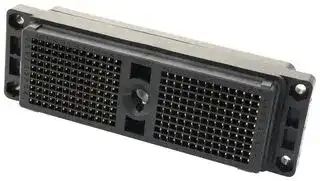


DL5-260RW6B.
ZIF CONNECTOR, RECEPTACLE, 260 POSITION, THROUGH HOLE
- Manufacturer: ITT CANNON
- Product type: Backplane Connectors
- Row Pitch: 2.54mm
- No. of Rows: 10Rows
- Pitch Spacing: 2.54mm
- Product Range: ITT Cannon DL Series
- Contact Plating: Gold Plated Contacts
- No. of Contacts: 260Contacts
- Contact Material: Copper Alloy
- Contact Termination Type: Through Hole
| Delivery and price | |
|---|---|
| Units per pack | 50 |
| Price | 238.75 € |
| Current stock | 10+ |
| Lead time | 30 days |
101
**ZIF Connectors**
**Contents**
**The Cannon Zero Insertion Force (ZIF) series of connectors provide versatile low-cost, high performance, multiple-wire power and signal connectors. This series can be mated/unmated in less than two seconds even with as many as 2,496 contacts. The long life and rapid mating are achieved through the ZIF design, where contacts in the plug and receptacle design do not touch each other while the connector halves are being engaged.**
> _On the Cover_ < _DL1, DLM6, DLM3, DL5, DLD2 (with and without contacts)_
|||**Introduction**||
|---|---|---|---|
||**Description**<br>**Page**|**Introduction**||
||**DL/DLM/DLD Drawer Connectors**|||
|>|**Selection Guide**<br>Product . . . . . . . . . . . . . . . . . . . . . . . . . . . . . . . . . . . . . . . . . . . . . . . . . . . 2-3<br>Series . . . . . . . . . . . . . . . . . . . . . . . . . . . . . . . . . . . . . . . . . . . . . . . . . . . . . . 3|**DL1, DLM1,**|**DLD1**|
||**Introduction**|||
||DL Materials and Finishes . . . . . . . . . . . . . . . . . . . . . . . . . . . . . . . . . . . . . . . 4|||
||DLM Materials and Finishes . . . . . . . . . . . . . . . . . . . . . . . . . . . . . . . . . . . . . . 5<br>DLD Drawer Materials and Finishes . . . . . . . . . . . . . . . . . . . . . . . . . . . . . . . . 6<br>DL4 Materials and Finishes . . . . . . . . . . . . . . . . . . . . . . . . . . . . . . . . . . . . . . 7<br>Product Features . . . . . . . . . . . . . . . . . . . . . . . . . . . . . . . . . . . . . . . . . . . . . . 8|**DL2, DLM2,**|**DLD2**|
||Applications . . . . . . . . . . . . . . . . . . . . . . . . . . . . . . . . . . . . . . . . . . . . . . . . . . 9|||
||Performance Specifications . . . . . . . . . . . . . . . . . . . . . . . . . . . . . . . . . . . . . . 9|||
||Mechanical Data . . . . . . . . . . . . . . . . . . . . . . . . . . . . . . . . . . . . . . . . . . . . . . 9<br>Temperature/Current Rating . . . . . . . . . . . . . . . . . . . . . . . . . . . . . . . . . . . . . 10<br>Test Data . . . . . . . . . . . . . . . . . . . . . . . . . . . . . . . . . . . . . . . . . . . . . . . . . . . 10|**DL3, DLM3**||
||How to Identify the Ideal DL Product for Your Application . . . . . . . . . . . . . . . 11|||
||How to Order . . . . . . . . . . . . . . . . . . . . . . . . . . . . . . . . . . . . . . . . . . . . . 12-13|||
|**DL Connectors – Plastic Body – Shell Dimensions**<br>e||||
||DL1 (156 Contacts) . . . . . . . . . . . . . . . . . . . . . . . . . . . . . . . . . . . . . . . . . 14-15|**DL4**||
||DL2 (96 Contacts) . . . . . . . . . . . . . . . . . . . . . . . . . . . . . . . . . . . . . . . . . 21-22|||
||DL3 (60 Contacts) . . . . . . . . . . . . . . . . . . . . . . . . . . . . . . . . . . . . . . . . . 28-29|||
||DL5 (260 Contacts) . . . . . . . . . . . . . . . . . . . . . . . . . . . . . . . . . . . . . . . . 35-36|||
|**DLM Connectors – Metal Body – Shell Dimensions**<br>DLM1 (156 Contacts) . . . . . . . . . . . . . . . . . . . . . . . . . . . . . . . . . . . . . . . 16-18<br>DLM2 (96 Contacts) . . . . . . . . . . . . . . . . . . . . . . . . . . . . . . . . . . . . . . . . 23-25<br>e||**DL5, DLM5**||
||DLM3 (60 Contacts) . . . . . . . . . . . . . . . . . . . . . . . . . . . . . . . . . . . . . . . . 30-32|||
||DLM5 (260 Contacts) . . . . . . . . . . . . . . . . . . . . . . . . . . . . . . . . . . . . . . . 37-39|||
||DLM6 (360 Contacts) . . . . . . . . . . . . . . . . . . . . . . . . . . . . . . . . . . . . . . . 40-42|||
|**DLD Drawer Connectors – Plastic Body – Shell Dimensions**<br>DLD1 (156 Contacts) . . . . . . . . . . . . . . . . . . . . . . . . . . . . . . . . . . . . . . . . 19-20<br>e||**DLM6**||
||DLD2 (96 Contacts) . . . . . . . . . . . . . . . . . . . . . . . . . . . . . . . . . . . . . . . . 26-27|||
|**DL Connectors – Metal Frame – Shell Dimensions**<br>e||||
|>|DL4 (624, 1248, 2496 Contacts) . . . . . . . . . . . . . . . . . . . . . . . . . . . . . . 33-34<br>**Selection Guide – Accessories** . . . . . . . . . . . . . . . . . . . . . . . . . . . . . . . . . . . . . . . . . . 43|**Accessories**||
||**Accessories** . . . . . . . . . . . . . . . . . . . . . . . . . . . . . . . . . . . . . . . . . . . . . . . . . . . . . . 43-49|||
||**Contacts** . . . . . . . . . . . . . . . . . . . . . . . . . . . . . . . . . . . . . . . . . . . . . . . . . . . . . . . . 50-53|||
||**Tools and Assembly** . . . . . . . . . . . . . . . . . . . . . . . . . . . . . . . . . . . . . . . . . . . . . . . 54-59<br>**Reader’s Resource**|**Contacts**||
||PCB Hole Patterns . . . . . . . . . . . . . . . . . . . . . . . . . . . . . . . . . . . . . . . . . 60-63|||
||PCB Pad Layouts . . . . . . . . . . . . . . . . . . . . . . . . . . . . . . . . . . . . . . . . . . . . . 64|||
||Panel Cutouts . . . . . . . . . . . . . . . . . . . . . . . . . . . . . . . . . . . . . . . . . . . . . 65-67<br>Contact Cavity Arrangements . . . . . . . . . . . . . . . . . . . . . . . . . . . . . . . . . 68-69<br>DLD Drawer Assembly Dimensions and Mating Sequence . . . . . . . . . . . . . . 70|**Tools and**|**Assembly**|
||Glossary of Terms . . . . . . . . . . . . . . . . . . . . . . . . . . . . . . . . . . . . . . . . . . . . 71|||
||Part Number Index . . . . . . . . . . . . . . . . . . . . . . . . . . . . . . . . . . . . . . . . . . . . 72|||
||Product Safety . . . . . . . . . . . . . . . . . . . . . . . . . . . . . . . . . . . . . . . . . . . . . . . 73|||
||Warranty . . . . . . . . . . . . . . . . . . . . . . . . . . . . . . . . . . . . . . . . . . . . . . . . . . . 73|**Reader’s**|**Resource**|
Cannon is a trademark of ITT Industries, Inc. in the United States.
Dimensions are shown in mm (inch) Dimensions subject to change
1
**Selection Guide**
**ZIF Connectors**
## DL
**DL1/2/3/5 Contents Page** Plastic Body. 60, 96, 156, or 260 Contact Cavities. Introduction . . . . . . . . . . . . . . . . . . . . 4 Single Hand Actuation. DL1-156 . . . . . . . . . . . . . . . . . . . . 14-15 Crimp or Square Post Contacts. DL2-96 . . . . . . . . . . . . . . . . . . . . 21-22 DL3-60 . . . . . . . . . . . . . . . . . . . . 28-29 DL5-260 . . . . . . . . . . . . . . . . . . . 35-36
## DLM
## **DLM1/2/3/5/6**
**Contents Page** Metal Body. EMI/RFI Shielding. Introduction . . . . . . . . . . . . . . . . . . . . 5 60, 96, 156, 260, or 360 Contact Cavities. DLM1-156 . . . . . . . . . . . . . . . . . . 16-18 Single Hand Actuation. Crimp, Square Post, or PC/RC Contacts. DLM2-96 . . . . . . . . . . . . . . . . . . . 23-25 DLM3-60 . . . . . . . . . . . . . . . . . . . 30-32 DLM5-260 . . . . . . . . . . . . . . . . . . 37-39 DLM6-360 . . . . . . . . . . . . . . . . . . 40-42
## DLD Drawer
## **DLD1/2**
**Contents Page** Drawer Style. Plastic Body. Introduction . . . . . . . . . . . . . . . . . . . . 6 96 or 156 Contact Cavities. DLD1-156 . . . . . . . . . . . . . . . . . . . 19-20 Sliding Actuation. Crimp or Square Post Contacts. DLD2-96 . . . . . . . . . . . . . . . . . . . 26-27
## DL4
## **DL4**
|**DL4**||
|---|---|
|Panel Mount.|**Contents**<br>**Page**|
|Metal Frame.|Introduction . . . . . . . . . . . . . . . . . . . . 7|
|624, 1248, or 2496 Contact Cavities.<br>Lever Actuation.|DL4-624 . . . . . . . . . . . . . . . . . . . 33-34|
|Crimp or Square Post Contacts.|DL4-1248 . . . . . . . . . . . . . . . . . . . . . . *|
||DL4-2496 . . . . . . . . . . . . . . . . . . . . . . *|
*Contact Cannon for details
Dimensions are shown in mm (inch) Dimensions subject to change ~~——ssSSSSSSSSii~~
2
**Selection Guide**
**ZIF Connectors**
## Accessories
## **Accessories**
Cannon offers a large selection of accessories to meet a variety of application requirements. Allows customization using standard components.
**Contents Page** Introduction . . . . . . . . . . . . . . . . . . . 43 Selection Guide . . . . . . . . . . . . . . . . . 43 Backshells, Metal . . . . . . . . . . . . . 44-45 Junction Shells, Plastic . . . . . . . . . . . 46 Actuating Handles . . . . . . . . . . . . . . . 47 Protective Covering . . . . . . . . . . . . . . 47 Polarizing Posts . . . . . . . . . . . . . . . . 48 Shells (EMI/RFI) . . . . . . . . . . . . . . . . 49
See Pages 43-49
## Contacts
**Contacts Contents Page** Crimp and Buss contacts are available loose or reeled. Introduction . . . . . . . . . . . . . . . . . . . 50 Accommodates wire sizes #42-#18 AWG. Buss Contacts . . . . . . . . . . . . . . . . . . 51 Customer installed. Field installable/ removeable. Crimp Contacts - Loose . . . . . . . . . . 52 Crimp Contacts - Reeled . . . . . . . . . . 53
See Pages 50-53
## Tools and Assembly
## **Tools and Assembly**
**Contents Page** Cannon offers hand crimp tooling for low volume applications. Introduction . . . . . . . . . . . . . . . . . . . 54 Contact extraction tools. Hand Crimp Tools . . . . . . . . . . . . . . . 55 Automatic tooling can be leased for large volume applications. Extraction Tools . . . . . . . . . . . . . . 54-55 Assembly Instructions . . . . . . . . . 56-58 Lease Automatic Tooling . . . . . . . . . . 59
See Pages 54-59
Series Selection — Available Size in Series by Number of Contacts
|**Number**||**Connector Series**||
|---|---|---|---|
|**of Contacts**|**DL**|**DLD**|**DLM**|
|60|DL3-60|—|DLM3-60|
|96|DL2-96|DLD2-96|DLM2-96|
|156|DL1-156|DLD1-156|DLM1-156|
|260|DL5-260|—|DLM5-260|
|360|—|—|DLM6-360|
|624|DL4-624|—|—|
|1248|DL4-1248*|—|—|
|2496|DL4-2496*|—|—|
*For DL4-1248 and DL4-2496 versions contact Cannon for details.
**==> picture [346 x 40] intentionally omitted <==**
**----- Start of picture text -----**<br>
Dimensions are shown in mm (inch)<br>Dimensions subject to changject to changect to changge<br>cmon<br>**----- End of picture text -----**<br>
Dimensions are shown in mm (inch) Dimensions subject to changject to changect to changge 3
**ZIF Connectors**
**DL**
##
## DL Product Introduction
he Cannon DL Series of Zero Insertion Force (ZIF) connectors fill the need in the **T** medical, commercial/industrial, computer and peripheral equipment market places for low-cost, high performance multiple-wire power and signal connectors.
DL connectors feature: a **minimum** rated life of 10,000 complete mating and unmating cycles with no performance loss; can be mated and unmated in less than two seconds even with as many as 2496 contacts; and they cost less (often as much as 25% less) per mated line than singular highdensity rack-and-panel connectors.
Simple. Effective. Reliable. Durable.
Combining their special design with commercialgrade materials and low cost crimp, PCB and wrappable hermaphroditic contacts, that may be hand or machine terminated, makes the DL Series of ZIF connectors the finest low-cost-per-matedline I/0 connectors available today.
## Materials and Finishes
DL1/2/3 Housing DL5 Housing Crimp Contact*
Square Post Contact
Actuating Camshaft Insulator Retainer (Plug Only)
Glass filled thermoplastic, UL 94V-1 rated, Color: Black Glass filled thermoplastic, UL 94V-0 rated, Color: Black
Copper alloy, 50 `µ` inches gold over 50 `µ` inches nickel in mating area, gold flash on balance Copper alloy, 20 `µ` inches gold over 50 `µ` inches nickel in mating area, tin lead on balance Copper alloy, 50 `µ` inches gold over 50 `µ` inches nickel in mating area, gold flash on balance Copper alloy, 20 `µ` inches gold over 50 `µ` inches nickel in mating area, gold flash on balance Stainless steel, Passivated Stainless steel, Passivated
*Order crimp contacts separately, see pages 52-53.
**==> picture [348 x 28] intentionally omitted <==**
**----- Start of picture text -----**<br>
Dimensions are shown in mm (inch)<br>Dimensions subject to changeject to changeect to changegee<br>Cannone<br>**----- End of picture text -----**<br>
Dimensions are shown in mm (inch) Dimensions subject to changeject to changeect to changegee
4
**ZIF Connectors**
**DLM**
## DLM Product Introduction
annon has expanded the DL-ZIF Series offering with the addition of the DLM **C** (Metal Shell) versions. The DLM uses a rugged nickel plated aluminum housing. The Shield-Locking Mechanism feature (see illustration below) ensures uniform mating pressure around the perimeter of the mated connector to create an EMI/RFI shield. Facilitates compliance of equipment to CE EMC directives.
The DLM1/2/3 connectors are an extension of the The DLM Series are offered with the 3,18(.125) DL line, similar to the current DLM5 and DLM6 long 0,64(.025) square post 50 `µ` inch gold products.The DLM series connectors are intercontacts, as well as the 4,50(.177) long mateable to the DL (Plastic) versions for X 0,50(.020) PC/RC round tail contacts. backwards/forwards compatibility.
## Materials and Finishes
DLM1/2/3/5/6 Housing DLM1/2/3/5/6 Insulator Crimp Contact*
Square Post Contact
PC/RC Contact Actuating Camshaft Insulator Retainer (Plug Only)
Aluminum alloy, nickel plated
Glass filled thermoplastic, UL 94V-0 rated, Color: Black
Copper alloy, 50 `µ` inches gold over 50 `µ` inches nickel in mating area, gold flash on balance Copper alloy, 20 `µ` inches gold over 50 `µ` inches nickel in mating area, tin lead on balance Copper alloy, 50 `µ` inches gold over 50 `µ` inches nickel in mating area, gold flash on balance Copper alloy, 20 `µ` inches gold over 50 `µ` inches nickel in mating area, gold flash on balance Copper alloy, 20 `µ` inches gold over nickel in mating area, tin lead on balance Stainless steel, Passivated Stainless steel, Passivated
*Order crimp contacts separately, see pages 52-53.
Dimensions are shown in mm (inch) Dimensions subject to changeject to changeect to changegee ~~sss~~
Dimensions are shown in mm (inch) Dimensions subject to changeject to changeect to changegee
5
**ZIF Connectors**
**DLD**
## DLD Drawer Product Introduction
annon has combined Zero Insertion Force (ZIF) technology with remote **C** electrical engagement. The DLD Drawer allows the movement of a drawer or panel to effortlessly mate/unmate the connector halves. As an example: electrical sub-systems can be easily removed for service, interchangability, or portability.
By specifying DLD Drawer interconnect systems, your packaging design is simplified as the need for expensive, complicated, and space-consuming manual actuation mechanisms is eliminated. Tight space requirements no longer restrict your use of ZIF connectors.
The contacts in the DLD Drawer product line do not touch each other while the connector halves are mating. This unique ZIF technology, introduced in the Cannon DL series in the early 1970’s, has time-tested proven reliability and durability.
The DLD Drawer’s remote mating feature utilizes the axial thrust of a cam to move and mate the contacts. At the end of the cam travel, the cam ramps on a flat surface thereby negating any uncoupling forces.
This rack-and-panel connector is available with crimp or square post contacts, allowing cable, PCB, or flat-flex termination.
## Materials and Finishes
DLD1/2 Housing Crimp Contact*
Square Post Contact
Insulator Retainer (Plug Only) Actuating Camshaft (Receptacle Only) Spring Mounting Screw (Receptacle Only) Compression Spring (Receptacle Only)
Glass Filled thermoplastic, UL 94V-1 rated, Color: Black
Copper alloy, 50 `µ` inches gold over 50 `µ` inches nickel in mating area, gold flash on balance Copper alloy, 20 `µ` inches gold over 50 `µ` inches nickel in mating area, tin lead on balance Copper alloy, 50 `µ` inches gold over 50 `µ` inches nickel in mating area, gold flash on balance Copper alloy, 20 `µ` inches gold over 50 `µ` inches nickel in mating area, gold flash on balance Stainless steel, Passivated Stainless steel Stainless steel, Passivated Music wire, zinc plated
*Order crimp contacts separately, see pages 52-53.
Dimensions are shown in mm (inch) Dimensions subject to change
6
**DL4**
**ZIF Connectors**
## DL4 Product Introduction
he Cannon DL4 Series of Zero Insertion Force (ZIF) connectors fill the need in the **T** commercial/industrial, aerospace/ military, computer and peripheral equipment marketplaces for low-cost, high performance multiple wire power and signal connectors. The DL4 Series is a panel mounted connector with easy actuating lever from the side.
DL connectors feature: a **minimum** rated life of 20,000 complete mating and unmating cycles with no performance loss; can be mated and unmated in less than two seconds even with as many as 2496 contacts; and they cost less (often as much as 25% less) per mated line than singular highdensity rack-and-panel connectors.
Simple. Effective. Reliable. Durable.
Combining their special design with commercialgrade materials and low cost crimp. PCB and wrappable hermaphroditic contacts, that may be hand or machine terminated, makes the DL Series of ZIF connectors the finest low-cost-per-matedline I/O connectors available today.
## Materials and Finishes
DL4 Insulator DL4 Housing Frame DL4 Mounting Plate Crimp Contact* Square Post Contact Actuating Camshaft Insulator Retainer (Plug Only)
Glass filled thermoplastic, UL 94V-1 rated, Color: Gray Aluminum alloy, cadmium plated Aluminum alloy, clear anodized Copper alloy, 50 `µ` inches gold over 50 `µ` inches nickel in mating area, gold flash on balance Copper alloy, 20 `µ` inches gold over 50 `µ` inches nickel in mating area, tin lead on balance Copper alloy, 50 `µ` inches gold over 50 `µ` inches nickel in mating area, gold flash on balance Copper alloy, 20 `µ` inches gold over 50 `µ` inches nickel in mating area, gold flash on balance Stainless steel, Passivated Stainless steel, Passivated
*Order crimp contacts separately, see pages 52-53.
Dimensions are shown in mm (inch) Dimensions subject to change 7
**DL/DLM**
**ZIF Connectors**
## DL/DLM Product Features
High pin count: 60, 96, 156, 260, 360, 624, 1248* or 2496* contact positions.
**Zero Insertion Force Camming Instructions**
Variety of contacts:
– Crimp
– Square Post
– Wrap Post
– Buss
– PC/RC
Metal or plastic housing.
Wide range of accessories.
Easy actuation by screwdriver, socket wrench (DL1/2/3 only), allen wrench or actuating handle (see accessories page 47).
The long life and rapid mating are achieved through the use of our Zero Insertion Force design. Contacts in the plug and receptacle do not touch each other while the connector halves are being engaged.
## **It’s as easy as 1, 2, 3...**
**This is our ‘‘DL/DLM’’ series of connectors.**
**Step 1.** The plug is placed over the receptacle. **Step 2.** A ‘‘quarter turn’’ of an actuating shaft mates all the contacts at once.
**Step 3.** The ‘‘same quarter’’ turn also physically locks the connector halves together.
Connector engagement force is zero, and the only wear on the contacts occurs as they are pressed together and lightly wiped past each other during the camming and locking operation.
*Contact Cannon for details.
**Step 1. Simply place it together.**
**Step 2. Turn the cam a quarter turn.**
**Step 3. It’s locked and mated.**
**Contacts aligned.**
**Contacts engaged.**
**Contacts are mated.**
Dimensions are shown in mm (inch) Dimensions subject to change
8
**DL/DLM/DLD**
**ZIF Connectors**
## DL/DLM/DLD Applications
## **Medical**
## **Signal and Power Distribution Cable Harness**
Ultrasound Diagnostic Patient Monitoring Hospital Equipment
## **Test & Instrumentation**
Avionics Automated Test Equipment Computer & Peripheral Equipment Semiconductor
## **Commercial/Industrial Manufacturing**
Automation Robotics Electrical Controls
## **Entertainment**
Recording Studio Equipment Stage Lighting & Sound Broadcasting Equipment
## **Telecommunication**
Systems Interconnect Manufacturing Test Equipment Switching Systems
## **Transportation**
Locomotive Systems Automotive Electronics Aircraft Simulators
For your complete cable harnessing resource, contact Cannon for details.
## DL/DLM/DLD Performance Specifications
Current Rating 5 A max. - Crimp/Square Post/PCB Contact 4 A max. - PC/RC Contact 10 A, 20 A, 30 A, 40 A, 50 A, 60 A max. - Buss Contact Dielectric Withstanding Voltage 1200 VAC RMS - Crimp/Square Post Contact 1000 VAC RMS - PC/RC Contact 750 VAC RMS - DL4 Operating Temperature -55 ° C to 105 ° C (DL/DLM/DLD) -55 ° C to 71 ° C (DL4) Durability 10,000 Cycles min. (DL/DLM) 20,000 Cycles min. (DL4) 100,000 Cycles min. (DLD) Contact Resistance 15 m max. - Crimp/Square Post Contact 20 m max. - Crimp #32 AWG - #30 AWG Contact 30 m max. - PC/RC Contact Insulation Resistance 5000 M min. Wire Accommodation #42 AWG-#18 AWG Contact Spacing 2,54 (.100) Square Grid Contact Retention: 8 lbs (35,585 N) min.
## DL/DLM/DLD Mechanical Data
Polarization Polarizing Posts Contact Termination PC Tails, Straight Crimp Square Post Wrap Post Buss
**==> picture [192 x 28] intentionally omitted <==**
**----- Start of picture text -----**<br>
Dimensions subjject to change<br>—sSSSSSSSSSiCiS<br>**----- End of picture text -----**<br>
Dimensions are shown in mm (inch) Dimensions subjject to change
9
**DL/DLM/DLD**
**ZIF Connectors**
##
## DL/DLM/DLD Temperature/Current Rating
## **DL1/DLM1/DLD1**
The ambient temperature curves shown represent the rated current carrying capacity of the Cannon DL1/2/3/4, DLM1/2/3 and DLD1/2 electrical connectors, derated to 80% of the values recorded using the methods specified by International Electro-Technical Commission Document 48 (1975).
Current was applied to the total connector (all contacts) in one-half ampere increments and maintained at each current level until thermal stability was achieved. A thermocouple inserted into the ‘‘hottest area’’ of each connector then measured the connector temperature at the same time that an ambient temperature reading was taken. The difference between the two measured values is the heat rise or self-heating created solely by the current flow, and this temperature rise for the current level was deducted from the insulator material rated temperature. These values were then derated to 80% to obtain the curves shown.
## **DL3/DLM3**
## **DL2/DLM2/DLD2**
## **DL4**
## DL/DLM/DLD Test Data
|**Test Description**|**MIL Standard**|**Test Method**|
|---|---|---|
|Dielectric WithstandingVoltage|MIL-STD-202|301|
|Contact Resistance|MIL-STD-202|307|
|Insulation Resistance|MIL-STD-202|302,Condition B|
|Humidity (Standard)|MIL-STD-202|103,Condition B|
|Humidity (DL4)|MIL-STD-202|106|
|Salt Spray|MIL-STD-202|101,Condition B(48 Hours)|
|Shock|MIL-STD-202|213,Condition A(50 G’s)|
|Vibration(Standard)|MIL-STD-202|204,Condition C|
|Vibration(DL4)|MIL-STD 167-1/2 Modified|—|
Dimensions are shown in mm (inch) Dimensions subject to change
10
**DL/DLM/DLD**
**ZIF Connectors**
## How to Identify the Ideal DL Product for Your Application
- **Q. What type of actuation does the application require?**
**Q. Does the application require plastic housing?**
**Q. Does the application require metal housing?**
**Q. Does this application involve low currents?**
- **Q. Does this application involve standard currents of more than 100 milliamps?**
- **Q. Does this application involve higher than 5 amps?**
- **Q. What type of contact is required for this application?**
**Q. Does the application require crimp contacts?**
- **A. Manual (turn handle cam) – DL / DLM series. Blind mating (self cam) – DLD drawer series.**
- **A. DL / DLD series.**
- **A. DLM series (for EMI / RFI shielding). DL4 series.**
- **A. For 100 milliamps or less use 50** `µ` **inch gold contacts (Flat contacts on Receptacle, and Bump contacts on Plug), see pages 52-53.**
- **A. For more than 100 milliamps, use 20** `µ` **inch gold contacts (Hermaphroditic Bump contact), see pages 52-53.**
- **A. For higher than 5 amps use Buss contacts, see page 51.**
- **A. Select the appropriate part number for the Plug and Receptacle based on the number and type of contacts needed for this application, see pages 12-13.**
- **A. Order appropriate crimp contacts for the wire size used in this application, see pages 50-53.**
- **50** `µ` **inch Gold (low current to 5 A applications) – Most Versatile**
- **20** `µ` **inch Gold (standard application) Buss contacts (high amps-greater than 5 A)**
- **Q. Does the application require crimp tooling, with low or high volume?**
**Q. Is an actuating handle needed?**
**Q. Does the application require fool-proof mating?**
- **Q. How do I protect the wiring / cabling?**
- **A. For low volume of crimps: Order loose contacts and order the appropriate hand tool, see page 55. For high volume of crimps (50,000 per year or more): Order reeled contacts, see page 53, and contact Cannon’s CustomerUse-Tooling to lease an automatic crimp machine, see page 59.**
- **A. Actuating handles are ordered separately (except DL4 Series), see page 47.**
- **A. Order the polarizing posts to protect from erroneous mating, see page 48.**
- **A. Two Options:**
- **Plastic Junction Shell with optional second entry cable clamp kit, see page 46.**
- **Metal Backshell available, see pages 44-45.**
- **Q. When the DL5-260 series application requires EMI / RFI shielding?**
- **Q. Does the customer need to protect the contacts when connector is not mated?**
- **A. Order the EMI / RFI metal shielding shells or utilize the new DLM5 series without shield shell, see page 49.**
- **A. Order the appropriate protective cover, see page 47.**
Dimensions are shown in mm (inch) Dimensions subject to change
11
**DL/DLM/DLD**
**ZIF Connectors**
##
## How to Order — Plug
|**Contact Style**|**Nomenclature**|**Part Number**|**Size**|**Type**|**No. of Contacts**|**Contact Style**|**Page Reference**|
|---|---|---|---|---|---|---|---|
|**Crimp AWG #42-#18**|DL1-156P|110535-0000|DL1|Plastic Body|156 Pin Connector|Crimp|14|
|(50µinches Gold, BUMP in Plug)|DLM1-156P|127050-0204|DLM1|Metal Body|156 Pin Connector|Crimp|16|
|Note: Crimp Contacts Sold Separately|DLD1-156P|111496-0000|DLD1|Plastic Body|156 Pin Connector|Crimp|19|
||DL2-96P|110777-0000|DL2|Plastic Body|96 Pin Connector|Crimp|21|
||DLM2-96P|127050-0212|DLM2|Metal Body|96 Pin Connector|Crimp|23|
||DLD2-96P|111922-0000|DLD2|Plastic Body|96 Pin Connector|Crimp|26|
||DL3-60P|110900-0008|DL3|Plastic Body|60 Pin Connector|Crimp|28|
||DLM3-60P|127050-0220|DLM3|Metal Body|60 Pin Connector|Crimp|30|
||DL4-624P|110959-0002|DL4|Metal Frame|624 Pin Connector|Crimp|33|
||DL4-1248P|110959-0003|DL4|Metal Frame|1248 Pin Connector|Crimp|**|
|** Similar to DL4-624, see pages 33-34.<br>Contact Cannon for details.|DL4-2496P<br>DL5-260P|110959-0004<br>111986-0014|DL4<br>DL5|Metal Frame<br>Plastic Body|2496 Pin Connector<br>260 Pin Connector|Crimp<br>Crimp|**<br>35|
||DLM5-260P|127050-0109|DLM5|Metal Body|260 Pin Connector|Crimp|37|
||DLM6-360P|127050-0034|DLM6|Metal Body|360 Pin Connector|Crimp|40|
|**Square Post 7,11 (.280) Ext.**|DL1-156PW6A*|110535-0030|DL1|Plastic Body|156 Pin Connector|Square Post|15|
|50µinches Gold, BUMP<br>Std. Square Post<br>0,64 (.025)<br>Factory Installed|DLM1-156PW6A*<br>DLD1-156PW6A*|112134-0000<br>111496-0002|DLM1<br>DLD1|Metal Body<br>Plastic Body|156 Pin Connector<br>156 Pin Connector|Square Post<br>Square Post|17<br>20|
|Solder to PCB Through Hole<br>Interconnect Termination|DL2-96PW6A*<br>DLM2-96PW6A*|110777-0025<br>112136-0000|DL2<br>DLM2|Plastic Body<br>Metal Body|96 Pin Connector<br>96 Pin Connector|Square Post<br>Square Post|22<br>24|
||DLD2-96PW6A*|111922-0002|DLD2|Plastic Body|96 Pin Connector|Square Post|27|
||DL3-60PW6A*|110900-0014|DL3|Plastic Body|60 Pin Connector|Square Post|29|
|* ‘‘A’’ designates plug contacts mandatory|DLM3-60PW6A*|112138-0000|DLM3|Metal Body|60 Pin Connector|Square Post|31|
|for low current applications less than<br>100 milliamps.|DL4-624PW6A*<br>DL5-260PW6A*|110959-0042<br>111986-0000|DL4<br>DL5|Metal Frame<br>Plastic Body|624 Pin Connector<br>260 Pin Connector|Square Post<br>Square Post|34<br>36|
||DLM5-260PW6A*|112086-0000|DLM5|Metal Body|260 Pin Connector|Square Post|38|
||DLM6-360PW6A*|111995-0000|DLM6|Metal Body|360 Pin Connector|Square Post|41|
|**Square Post 3,18 (.125) Ext.**|DL110535-40|110535-0040|DL1|Plastic Body|156 Pin Connector|Square Post|15|
|50µinches Gold, BUMP<br>Std. Square Post<br>0,64 (.025)<br>Factory Installed|DLM112134-2<br>DLM112136-2|112134-0002<br>112136-0002|DLM1<br>DLM2|Metal Body<br>Metal Body|156 Pin Connector<br>96 Pin Connector|Square Post<br>Square Post|17<br>24|
|Solder to PCB Through Hole|DLM112138-2|112138-0002|DLM3|Metal Body|60 Pin Connector|Square Post|31|
||DLM112086-3|112086-0003|DLM5|Metal Body|260 Pin Connector|Square Post|38|
||DLM111995-7|111995-0007|DLM6|Metal Body|360 Pin Connector|Square Post|41|
|**Wrap Post 15,37 (.605) Ext.**|DL1-156PW4A*|110535-0025|DL1|Plastic Body|156 Pin Connector|WrapPost|15|
|50µinches Gold, BUMP<br>Std. Square Post<br>0,64 (.025)<br>Factory Installed|DLM1-156PW4A*<br>DLD1-156PW4A*|112134-0001<br>111496-0001|DLM1<br>DLD1|Metal Body<br>Plastic Body|156 Pin Connector<br>156 Pin Connector|WrapPost<br>WrapPost|17<br>20|
||DL2-96PW4A*|110777-0022|DL2|Plastic Body|96 Pin Connector|WrapPost|22|
||DLM2-96PW4A*|112136-0001|DLM2|Metal Body|96 Pin Connector|WrapPost|24|
||DLD2-96PW4A*|111922-0001|DLD2|Plastic Body|96 Pin Connector|WrapPost|27|
||DL3-60PW4A*|110900-0013|DL3|Plastic Body|60 Pin Connector|WrapPost|29|
|* ‘‘A’’ designates plug contacts mandatory<br>for low current applications less than<br>100 milliamps.|DLM3-60PW4A*<br>DL4-624PW4A*|112138-0001<br>110959-0035|DLM3<br>DL4|Metal Body<br>Metal Frame|60 Pin Connector<br>624 Pin Connector|WrapPost<br>WrapPost|31<br>34|
||DL5-260PW4A*|111986-0003|DL5|Plastic Body|260 Pin Connector|WrapPost|36|
||DLM5-260PW4A*|112086-0002|DLM5|Metal Body|260 Pin Connector|WrapPost|38|
||DLM6-360PW4A*|111995-0001|DLM6|Metal Body|360 Pin Connector|WrapPost|41|
|**Square Post 7,11 (.280) Ext.**|DL1-156PW6|110535-0026|DL1|Plastic Body|156 Pin Connector|Square Post|15|
|20µinches Gold, Hermophroditic||||||||
|Std. Square Post<br>0,64 (.025)||||||||
|Factory Installed||||||||
|Solder to PCB Through Hole||||||||
|**Wrap Post 15,37 (.605) Ext.**|DL1-156PW4|110535-0012|DL1|Plastic Body|156 Pin Connector|WrapPost|15|
|20µinches Gold, Hermophroditic<br>Std. Square Post<br>0,64 (.025)<br>Factory Installed|DL2-96PW4<br>DL3-60PW4|110777-0008<br>110900-0006|DL2<br>DL3|Plastic Body<br>Plastic Body|96 Pin Connector<br>60 Pin Connector|WrapPost<br>WrapPost|22<br>29|
||DL4-624PW4|110959-0011|DL4|Metal Frame|624 Pin Connector|WrapPost|34|
|**PC / RC 4,50 (.177) Ext.**|DLM1-156PC|127050-0207|DLM1|Metal Body|156 Pin Connector|PC|18|
|20µinches Gold - 4 A max.<br>Round Tail -X0,50 (.020)<br>Factory Installed|DLM2-96PC<br>DLM3-60PC|127050-0215<br>127050-0223|DLM2<br>DLM3|Metal Body<br>Metal Body|96 Pin Connector<br>60 Pin Connector|PC<br>PC|25<br>32|
|Solder to PCB Through Hole|DLM5-260PC|127050-0111|DLM5|Metal Body|260 Pin Connector|PC|39|
||DLM6-360PC|127050-0097|DLM6|Metal Body|360 Pin Connector|PC|42|
Note: 50 `µ` inches gold contacts (Bump on plug side, Flat on receptacle side) are mandatory for applications with less than 100 milliamps.
Dimensions are shown in mm (inch) Dimensions subject to changject to changect to changge ~~Cannone~~
Dimensions are shown in mm (inch) Dimensions subject to changject to changect to changge
12
**DL/DLM/DLD**
**ZIF Connectors**
## How to Order — Receptacle
|**Contact Style**|**Nomenclature**|**Part Number**|**Size**|**Type**|**No. of Contacts**|**Contact Style**|**Page Reference**|
|---|---|---|---|---|---|---|---|
|**Crimp AWG #42-#18**|DL1-156R|086-0030-000|DL1|Plastic Body|156 Pin Connector|Crimp|14|
|(50µinches Gold, FLAT in Receptacle)|DLM1-156R|127050-0208|DLM1|Metal Body|156 Pin Connector|Crimp|16|
|Note: Crimp Contacts Sold Separately|DLD1-156R|111497-0004|DLD1|Plastic Body|156 Pin Connector|Crimp|19|
||DL2-96R|086-0031-000|DL2|Plastic Body|96 Pin Connector|Crimp|21|
||DLM2-96R|127050-0216|DLM2|Metal Body|96 Pin Connector|Crimp|23|
||DLD2-96R|111921-0000|DLD2|Plastic Body|96 Pin Connector|Crimp|26|
||DL3-60R|086-0032-000|DL3|Plastic Body|60 Pin Connector|Crimp|28|
||DLM3-60R|127050-0224|DLM3|Metal Body|60 Pin Connector|Crimp|30|
||DL4-624R|110960-0002|DL4|Metal Frame|624 Pin Connector|Crimp|33|
|** Similar to DL4-624, see pages 33-34.|DL4-1248R|110960-0003|DL4|Metal Frame|1248 Pin Connector|Crimp|**|
|Contact Cannon for details.|DL4-2496R|110960-0004|DL4|Metal Frame|2496 Pin Connector|Crimp|**|
||DL5-260R|086-4501-000|DL5|Plastic Body|260 Pin Connector|Crimp|35|
||DLM5-260R|127050-0110|DLM5|Metal Body|260 Pin Connector|Crimp|37|
||DLM6-360R|127050-0045|DLM6|Metal Body|360 Pin Connector|Crimp|40|
|**Square Post 7,11 (.280) Ext.**|DL1-156RW6B*|110536-1007|DL1|Plastic Body|156 Pin Connector|Square Post|15|
|50µinches Gold, FLAT<br>Std. Square Post<br>0,64 (.025)<br>Factory Installed|DLM1-156RW6B*<br>DLD1-156RW6B*|112135-0000<br>111497-0010|DLM1<br>DLD1|Metal Body<br>Plastic Body|156 Pin Connector<br>156 Pin Connector|Square Post<br>Square Post|17<br>20|
|Solder to PCB Through Hole<br>Interconnect Termination|DL2-96RW6B*<br>DLM2-96RW6B*|110855-0014<br>112137-0000|DL2<br>DLM2|Plastic Body<br>Metal Body|96 Pin Connector<br>96 Pin Connector|Square Post<br>Square Post|22<br>24|
||DLD2-96RW6B*|111921-0002|DLD2|Plastic Body|96 Pin Connector|Square Post|27|
||DL3-60RW6B*|110901-0010|DL3|Plastic Body|60 Pin Connector|Square Post|29|
||DLM3-60RW6B*|112139-0000|DLM3|Metal Body|60 Pin Connector|Square Post|31|
|* ‘‘B’’ designates receptacle contacts<br>manditory for low current applications less<br>than 100 milliamps.|DL4-624RW6B*<br>DL5-260RW6B*<br>DLM5-260RW6B*|110960-0048<br>111987-0000<br>112087-0000|DL4<br>DL5<br>DLM5|Metal Frame<br>Plastic Body<br>Metal Body|624 Pin Connector<br>260 Pin Connector<br>260 Pin Connector|Square Post<br>Square Post<br>Square Post|34<br>36<br>38|
||DLM6-360RW6B*|111996-0001|DLM6|Metal Body|360 Pin Connector|Square Post|41|
|**Square Post 3,18 (.125) Ext.**|DL110536-1011|110536-1011|DL1|Plastic Body|156 Pin Connector|Square Post|15|
|50µinches Gold, FLAT<br>Std. Square Post<br>0,64 (.025)<br>Factory Installed|DLM112135-2<br>DLM112137-2|112135-0002<br>112137-0002|DLM1<br>DLM2|Metal Body<br>Metal Body|156 Pin Connector<br>96 Pin Connector|Square Post<br>Square Post|17<br>24|
|Solder to PCB Through Hole|DLM112139-2|112139-0002|DLM3|Metal Body|60 Pin Connector|Square Post|31|
||DLM112087-3|112087-0003|DLM5|Metal Body|260 Pin Connector|Square Post|38|
||DLM111996-5|111996-0005|DLM6|Metal Body|360 Pin Connector|Square Post|41|
|**Wrap Post 15,37 (.605) Ext.**|DL1-156RW4B*|110536-1006|DL1|Plastic Body|156 Pin Connector|WrapPost|15|
|50µinches Gold, FLAT<br>Std. Square Post<br>0,64 (.025)<br>Factory Installed|DLM1-156RW4B*<br>DLD1-156RW4B*|112135-0001<br>111497-0009|DLM1<br>DLD1|Metal Body<br>Plastic Body|156 Pin Connector<br>156 Pin Connector|WrapPost<br>WrapPost|17<br>20|
||DL2-96RW4B*|110855-0013|DL2|Plastic Body|96 Pin Connector|WrapPost|22|
||DLM2-96RW4B*|112137-0001|DLM2|Metal Body|96 Pin Connector|WrapPost|24|
||DLD2-96RW4B*|111921-0001|DLD2|Plastic Body|96 Pin Connector|WrapPost|27|
||DL3-60RW4B*|110901-0009|DL3|Plastic Body|60 Pin Connector|WrapPost|29|
|* ‘‘B’’ designates receptacle contacts<br>manditory for low current applications less<br>than 100 milliamps.|DLM3-60RW4B*<br>DL4-624RW4B*<br>DL5-260RW4B*|112139-0001<br>110960-0045<br>111987-0001|DLM3<br>DL4<br>DL5|Metal Body<br>Metal Frame<br>Plastic Body|60 Pin Connector<br>624 Pin Connector<br>260 Pin Connector|WrapPost<br>WrapPost<br>WrapPost|31<br>34<br>36|
||DLM5-260RW4B*|112087-0001|DLM5|Metal Body|260 Pin Connector|WrapPost|38|
||DLM6-360RW4B*|111996-0000|DLM6|Metal Body|360 Pin Connector|WrapPost|41|
|**Square Post 7,11 (.280) Ext.**|DL1-156RW6|110536-1009|DL1|Plastic Body|156 Pin Connector|Square Post|15|
|20µinches Gold, Hermophroditic||||||||
|Std. Square Post<br>0,64 (.025)||||||||
|Factory Installed||||||||
|Solder to PCB Through Hole||||||||
|**Wrap Post 15,37 (.605) Ext.**|DL1-156RW4|110536-1003|DL1|Plastic Body|156 Pin Connector|WrapPost|15|
|20µinches Gold, Hermophroditic<br>Std. Square Post<br>0,64 (.025)<br>Factory Installed|DL2-96RW4<br>DL3-60RW4|110855-0008<br>110901-0004|DL2<br>DL3|Plastic Body<br>Plastic Body|96 Pin Connector<br>60 Pin Connector|WrapPost<br>WrapPost|22<br>29|
||DL4-624RW4|110960-0022|DL4|Metal Frame|624 Pin Connector|WrapPost|34|
|**PC / RC 4,50 (.177) Ext.**|DLM1-156RC|127050-0211|DLM1|Metal Body|156 Pin Connector|RC|18|
|20µinches Gold - 4 A max.<br>Round Tail -X0,50 (.020)<br>Factory Installed|DLM2-96RC<br>DLM3-60RC|127050-0219<br>127050-0227|DLM2<br>DLM3|Metal Body<br>Metal Body|96 Pin Connector<br>60 Pin Connector|RC<br>RC|25<br>32|
|Solder to PCB Through Hole|DLM5-260RC|127050-0112|DLM5|Metal Body|260 Pin Connector|RC|39|
||DLM6-360RC|127050-0098|DLM6|Metal Body|360 Pin Connector|RC|42|
Note: 50 `µ` inches gold contacts (Bump on plug side, Flat on receptacle side) are mandatory for applications with less than 100 milliamps.
Dimensions are shown in mm (inch) Dimensions subject to changject to changect to changge ~~Cannone~~
Dimensions are shown in mm (inch) Dimensions subject to changject to changect to changge 13
**DL1**
**ZIF Connectors**
## DL1 — Plastic Body — 156 Pin Connectors — Crimp Contacts
**==> picture [15 x 30] intentionally omitted <==**
**----- Start of picture text -----**<br>
DLD1<br>DL1, DLM1,<br>**----- End of picture text -----**<br>
**==> picture [16 x 9] intentionally omitted <==**
**----- Start of picture text -----**<br>
Plug<br>**----- End of picture text -----**<br>
For contact cavity arrangement, see page 68. For panel cutout and mounting hole pattern, see page 65.
Crimp contacts are to be ordered separately and installed by customer, see pages 52-53. Order actuating handle kit separately, see page 47.
**==> picture [145 x 22] intentionally omitted <==**
**----- Start of picture text -----**<br>
Part Number Nomenclature<br>oo<br>110535-0000 DL1-156P<br>**----- End of picture text -----**<br>
**==> picture [275 x 299] intentionally omitted <==**
**----- Start of picture text -----**<br>
108,00 (4.255)<br>100,03 (3.938)<br>92,26 (3.631) 16,26 (.640)<br>4X Ø 3,03 (.119)<br>24,90 (.980)<br>7,92 (.312)<br>23,10<br>(.910)<br>a | 6,35 |<br>(.250)<br>54,81<br>(2.158)<br>i<br>CAMSHAFT<br>_ TURNING DIRECTION |<br>20,10<br>(.792)<br>t<br>92,10 (3.626)<br>**----- End of picture text -----**<br>
## **Receptacle**
For contact cavity arrangement, see page 68. For panel cutout and mounting hole pattern, see page 65. Crimp contacts are to be ordered separately and installed by customer, see pages 52-53.
**Part Number Nomenclature** 086-0030-000 DL1-156R
**==> picture [347 x 342] intentionally omitted <==**
**----- Start of picture text -----**<br>
108,00 (4.255)<br>100,03 (3.938)<br>16,26 (.640)<br>92,00 (3.622)<br>4X Ø 3,03 (.119)<br>24,90 (.980)<br>7,75 (.305)<br>20,32 (.800)<br>| :<br>6,35 (.250)<br>o SP<br>* CSenesieinieesiea BEDSEBSESoSH © mal 20,10 (.792)<br>92,10 (3.626)<br>Dimensions are shown in mm (inch)<br>Dimensions subject to changject to changect to changge<br>Cannone<br>**----- End of picture text -----**<br>
Dimensions are shown in mm (inch) Dimensions subject to changject to changect to changge
14
**DL1**
**ZIF Connectors**
## DL1 — Plastic Body — 156 Pin Connectors — Square Post Contacts
## **Plug**
**==> picture [503 x 609] intentionally omitted <==**
**----- Start of picture text -----**<br>
108,00 (4.255)<br>100,03 (3.938)<br>92,26 (3.631) 16,26 (.640)<br>4X Ø 3,03 (.119)<br>24,90 (.980)<br>" i 7,92 (.312) qu<br>a 27,75<br>° For contact cavity arrangement, see page 68. A (1.093)<br>e For panel cutout and mounting hole pattern, a ee<br>see page 65.<br>. For PC hole pattern, see page 60. | ATTN iy ATT<br>Front Removable 0,64 (.025) Square Posts 50,16<br>6,35 (.250) (1.975)<br>2,54 (.100) Centers. 0,64 (.025)<br>Order actuating handle kit separately,<br>see page 47.<br>. Ho |<br>CAMSHAFT<br>a TURNING DIRECTION 20,10 (.792)<br>5 SPACES @ 2,54 (.100)<br>Part Number Nomenclature A = 12,70 (.500)<br>110535-0012 DL1-156PW4 15,37 (.605)<br>110535-0025 DL1-156PW4A 15,37 (.605)<br>Te 110535-0026 DL1-156PW6 7,11 (.280) 12 SPACES @ 2,54 (.100) [i Ls 12 SPACES @ 2,54 (.100)<br>110535-0030 DL1-156PW6A 7,11 (.280) = 30,48 (1.200) = 30,48 (1.200)<br>110535-0040 DL110535-40 3,18 (.125) 92,10 (3.626)<br>Receptacle<br>108,00 (4.255)<br>100,03 (3.938)<br>92,00 (3.622) 16,26 (.640)<br>4X Ø 3,03 (.119)<br>For contact cavity arrangement, see page 68. 24,90 (.980)<br>For panel cutout and mounting hole pattern,<br>see page 65. 7,75 (.305)<br>For PC hole pattern, see page 60.<br>Front Removable 0,64 (.025) Square Posts<br>2,54 (.100) Centers.<br>A<br>24,97 (.983)<br>o 0,64 (.025) | 6,35 (.250)<br>5 SPACES @ 2,54 (.100)<br>= 12,70 (.500)<br>Part Number Nomenclature A 20,10 (.792)<br>110536-1003 DL1-156RW4 15,37 (.605)<br>Te 110536-1006 DL1-156RW4B 15,37 (.605) 12 SPACES @ 2,54 (.100) |, Ld 12 SPACES @ 2,54 (.100)<br>110536-1009 DL1-156RW6 7,11 (.280) = 30,48 (1.200) = 30,48 (1.200)<br>110536-1007 DL1-156RW6B 7 11 (.280) 92,10 (3.626)<br>**----- End of picture text -----**<br>
|**Part Number**|**Nomenclature**|**A**|
|---|---|---|
|110535-0012|DL1-156PW4|15,37 (.605),37 (.605)37 (.605)(.605).605))|
|110535-0025<br>DL1-156PW4A<br>15,37 (.605),37 (.605)37 (.605)(.605).605))<br>110535-0026<br>DL1-156PW6<br>7,11 (.280),11 (.280)11 (.280)(.280).280))<br>110535-0030<br>DL1-156PW6A<br>7,11 (.280),11 (.280)11 (.280)(.280).280))<br>~~Te~~|||
|110535-0040|DL110535-40|3,18 (.125),18 (.125)18 (.125)(.125).125))|
## **Receptacle**
|**Part Number**|**Nomenclature**|**A**|
|---|---|---|
|110536-1003<br>DL1-156RW4<br>15,37 (.605),37 (.605)37 (.605)(.605).605))<br>110536-1006<br>DL1-156RW4B<br>15,37 (.605),37 (.605)37 (.605)(.605).605))<br>110536-1009<br>DL1-156RW6<br>7,11 (.280),11 (.280)11 (.280)(.280).280))<br>~~Te~~|||
|110536-1007|DL1-156RW6B|7,11 (.280)(.280).280))|
|110536-1011|DL110536-1011|3,18(.125)|
Dimensions are shown in mm (inch) Dimensions subject to change
15
**DLM1**
**ZIF Connectors**
## DLM1 — Metal Body — 156 Pin Connectors — Crimp Contacts
## **Plug**
**==> picture [15 x 30] intentionally omitted <==**
**----- Start of picture text -----**<br>
DLD1<br>DL1, DLM1,<br>**----- End of picture text -----**<br>
For contact cavity arrangement, see page 68. For panel cutout and mounting hole pattern, see page 65.
Crimp contacts are to be ordered separately and installed by customer, see pages 52-53. Order actuating handle kit separately, see page 47.
**Part Number Nomenclature** 127050-0204 DLM1-156P
**==> picture [140 x 210] intentionally omitted <==**
**----- Start of picture text -----**<br>
7,92 (.312)<br>Oe aon<br>23,10<br>bb Ze i (.910)<br>6,35 90,00<br>(.250) (3.546)<br>54,10<br>(2.132)<br>CAMSHAFT<br>_ TURNING DIRECTION<br>20,10<br>rg|iere ee i ene!iema,4 | (.792)<br>92,10 (3.629)<br>**----- End of picture text -----**<br>
## **Receptacle**
For contact cavity arrangement, see page 68. For panel cutout and mounting hole pattern, see page 65.
Crimp contacts are to be ordered separately and installed by customer, see pages 52-53.
**==> picture [257 x 256] intentionally omitted <==**
**----- Start of picture text -----**<br>
1 08,00 (4.255)<br>1 00,03 (3.938)<br>9 2,00 (3.625) 16,26 (.640)<br>2X Ø 2,30 (ANA L S a AS)<br>(.091)<br>4X Ø 3,20 malVS2.eT AN,I _ t<br>(.126)<br> 24,80 (.977)<br>7,75 (.305)<br>20,55<br>(.810)<br>6,35<br>(.250)<br>20,10<br>ba OPE@@ Dogosgoogoo00® RERPEEEES (chy GaReeOO00000000000ee eee © @ ®2] (.792)<br>as [@] [4 SOOSSeHeCeee0 [oo000000000000] | NZ@ooosqo0000008SOSeOseeoo0s0| 6KxRSi ,<br>9 2,10 (3.629)<br>c b a Z Y X W V U T S R P N M L K J H G F E D C B A<br>ANNON ITT C<br>**----- End of picture text -----**<br>
**Part Number Nomenclature** 127050-0208 DLM1-156R
Dimensions are shown in mm (inch) Dimensions subject to change
16
**DLM1**
**ZIF Connectors**
## DLM1 — Metal Body — 156 Pin Connectors — Square Post Contacts
## **Plug**
For contact cavity arrangement, see page 68. For panel cutout and mounting hole pattern, see page 65. For PC hole pattern, see page 60. Front Removable 0,64 (.025) Square Posts 2,54 (.100) Centers. Order actuating handle kit separately, see page 47.
|**Part Number**<br>**Nomenclature**<br>**A**<br>112134-0001<br>DLM1-156PW4A<br>15,37(.605)<br>112134-0000<br>DLM1-156PW6A<br>7,11(.280)<br>~~AN~~|
|---|
|112134-0002<br>DLM112134-2<br>3,18(.125)|
**==> picture [324 x 296] intentionally omitted <==**
**----- Start of picture text -----**<br>
108,00 (4.255)<br>100,03 (3.938)<br>16,26 (.640)<br>92,00 (3.625)<br>2X Ø 2,30<br>4X Ø 3,20(.091) ||[esesasasasans)Y” eseseeseees| |X]<br>(.126) 24,80 (.977)<br>SSS7,92 (.312)<br>PaO OM RUUD UM UBUD aemmsZ ddd i<br>lag J RRRRERECRERZIyZe aia: + 693)<br>ICT TMMa 6,35 49,45<br>.250 5<br>5 0,64 (.025)| | (250) (1.948)<br>CAMSHAFT<br>5 SPACES @ 2,54 (.100) Sa TURNING DIRECTION<br>= 12,70 (.500) S02 ©<br> onmererreri merrrereees s |? (.792)20,10<br>12 SPACES @ 2,54 (.100) _—__———ee _————ee ee —e a ) 12 SPACES @ 2,54 (.100)<br>= 30,48 (1.200) = 30,48 (1.200)<br>92,10 (3.629)<br>c b Z Y X W V U T S R P N M L K J H G F E D C B A 1<br>2<br>3<br>4<br>5<br>6<br>c b a Z Y X W V U T S R P N M L K J H G F E D C B A<br>**----- End of picture text -----**<br>
## **Receptacle**
For contact cavity arrangement, see page 68. For panel cutout and mounting hole pattern, see page 65. For PC hole pattern, see page 60. Front Removable 0,64 (.025) Square Posts 2,54 (.100) Centers.
|**Part Number**|**Nomenclature**|**A**|
|---|---|---|
|112135-0001|DLM1-156RW4B|15,37(.605)|
|112135-0000|DLM1-156RW6B|7,11(.280)|
|112135-0002|DLM112135-2|3,18(.125)|
**==> picture [322 x 258] intentionally omitted <==**
**----- Start of picture text -----**<br>
1 08,00 (4.255)<br>1 00,03 (3.938)<br>9 2,00 (3.625) 16,26 (.640)<br>2X Ø 2,30<br>(.091)<br>ml<br>4X Ø 3,20<br>(.126) 24,80 (.977)<br>ATT | ______T | 7,75 (.305) f<br>25,20<br>(.992)<br>A<br>6,35<br>(.250)<br>a 0,64 (.025) |<br>5 SPACES @ 2,54 (.100) (+, = co<br>= 12,70 (.500)<br>20,10<br>[|zy Sogoossosc9esHOOOOO0000000)eS SS SS7 Gaaaaceooooose)PEEEEEHCe ®) —| (.792)<br>12 SPACES @ 2,54 (.100) |_| LT 12 SPACES @ 2,54 (.100)<br>= 30,48 (1.200) = 30,48 (1.200)<br>92,10 (3.629)<br>c b Z Y X W V U T S R P N M L K J H G F E D C B A 6<br>5<br>4<br>3 2 1<br>c b a Z Y X W V U T S R P N M L K J H G F E D C B A<br>**----- End of picture text -----**<br>
Dimensions are shown in mm (inch) Dimensions subject to change
17
**DLM1**
**ZIF Connectors**
## DLM1 — Metal Body — 156 Pin Connectors — PC/RC Contacts
**==> picture [15 x 30] intentionally omitted <==**
**----- Start of picture text -----**<br>
DLD1<br>DL1, DLM1,<br>**----- End of picture text -----**<br>
## **Plug**
For contact cavity arrangement, see page 68. For panel cutout and mounting hole pattern, see page 65. For PC hole pattern, see page 60. Order actuating handle kit separately, see page 47.
**==> picture [120 x 19] intentionally omitted <==**
**----- Start of picture text -----**<br>
Part Number Nomenclature<br>127050-0207 DLM1-156PC<br>**----- End of picture text -----**<br>
## **Receptacle**
For contact cavity arrangement, see page 68. For panel cutout and mounting hole pattern, see page 65. For PC hole pattern, see page 60.
**Part Number Nomenclature** 127050-0211 DLM1-156RC
**==> picture [323 x 600] intentionally omitted <==**
**----- Start of picture text -----**<br>
108,00 (4.255)<br>100,03 (3.938)<br>16,26 (.640)<br>92,00 (3.625)<br>2X Ø 2,30<br>(.091) (ieeePA elie<br>2s||[ebsssasaaasas) seseeeerees| |)<br>4X Ø 3,20 ee es.) |<br>(.126) 24,80 (.977)<br>SS——— 7,92 (.312)<br>on<br>27,75<br>(1.093)<br>4,60 (.181)<br>90,00<br>(3.546)<br>6,35<br>(.250)<br>Ø 0,50 (.020)<br>49,45<br>(1.948)<br>CAMSHAFT<br>_ TURNING DIRECTION<br>5 SPACES @ 2,54 (.100)= 12,70 (.500) cs cy<br>R E a ERE | 7 (.792)20,10<br>eS SS SS pT<br>ee<br>12 SPACES @ 2,54 (.100) 12 SPACES @ 2,54 (.100)<br>= 30,48 (1.200) = 30,48 (1.200)<br>92,10 (3.629)<br>1 08,00 (4.255)<br>100,03 (3.938)<br>16,26 (.640)<br>92,00 (3.625)<br>2X Ø 2,30<br>(.091)<br>4X Ø 3,20 KONECS ee = IPSies<br>(.126)<br>24,80 (.977)<br>7,75 (.305)<br>ART CT<br>25,20<br>(.992)<br>4,60 (.181)<br>6,35<br>(.250)<br>Ø 0,50 (.020) _ | -<br>5 SPACES @ 2,54 (.100)<br>= 12,70 (.500) €P = a<br>20,10<br>[| Sogsossescce— \QW7/ Gapssssccooqs@)} (.792)<br>r e —_reeee— re k a<br>12 SPACES @ 2,54 (.100 ) ee 12 SPACES @ 2,54 (.100)<br>= 30,48 (1.200) = 30,48 (1.200)<br>9 2,10 (3.629)<br>c b Z Y X W V U T S R P N M L K J H G F E D C B A 1<br>2<br>3<br>4<br>5<br>6<br>c b c Z Y X W V U T S R P N M L K J H G F E D C B A<br>c b a Z Y X W V U T S R P N M L K J H G F E D C B A 6<br>5<br>4<br>3<br>2<br>1 c b a Z Y X W V U T S R P N M L K J H G F E D C B A<br>**----- End of picture text -----**<br>
Dimensions are shown in mm (inch) Dimensions subject to change
18
**DLD1**
**ZIF Connectors**
## DLD1 — Plastic Body — 156 Pin Connectors — Crimp Contacts
## **Plug**
For contact cavity arrangement, see page 68. For panel cutout and mounting hole pattern, see page 66.
Crimp contacts are to be ordered separately and installed by customer, see pages 52-53. For assembly dimensions and mating sequence, see page 70.
**==> picture [206 x 235] intentionally omitted <==**
**----- Start of picture text -----**<br>
108,00 (4.255)<br>100,03 (3.938)<br>92,26 (3.631) 16,26 (.640)<br>4X Ø 3,03<br>(.119) 24,90 (.980)<br>7,92 (.312)<br>23,10 (.910)<br>—<br>6,35 (.250)<br>20,10 (.792)<br>92,10 (3.626)<br>**----- End of picture text -----**<br>
**Part Number Nomenclature** 111496-0000 DLD1-156P
## **Receptacle**
For contact cavity arrangement, see page 68. For panel cutout and mounting hole pattern, see page 66. Crimp contacts are to be ordered separately and installed by customer, see pages 52-53. For assembly dimensions and mating sequence, see page 70.
**Part Number Nomenclature** 111497-0004 DLD1-156R
**==> picture [336 x 271] intentionally omitted <==**
**----- Start of picture text -----**<br>
127,81 (5.032) REF<br>108,00 (4.255)<br>1 00,03 (3.938)<br>92,00 (3.622) 16,26 (.640)<br>24,90 (.980)<br>CAM, ACTUATOR<br>RECEPTACLE CONNECTOR<br>ASSEMBLY<br>7,75 (.305)<br>20,32 (.800)<br>46,86<br>(1.845) a 7<br>L= E —<br>6,35 (.250)<br>FRONT MOUNTING<br>PLATE-ASSEMBLY<br>3,18 (.125) REF [SUPPLIED BY CUSTOMER]<br>2,03 (.080) REF 4X SPRING,<br>COMPRESSION REAR PANEL, MOUNTING<br>4X SCREW, SPRING NO. 4-40 UNC SCREW [STATIONARY]<br>MOUNTING [SUPPLIED BY CUSTOMER] [SUPPLIED BY CUSTOMER]<br>20,10 (.792)<br>92,10 (3.626)<br>**----- End of picture text -----**<br>
Dimensions are shown in mm (inch) Dimensions subject to change
19
**DLD1**
**ZIF Connectors**
## DLD1 — Plastic Body — 156 Pin Connectors — Square Post Contacts
## **Plug**
For contact cavity arrangement, see page 68. For panel cutout and mounting hole pattern, see page 66.
For PC hole pattern, see page 60. Front Removable 0,64 (.025) Square Posts 2,54 (.100) Centers. For assembly dimensions and mating sequence, see page 70.
|**Part Number**|**Nomenclature**|**A**|
|---|---|---|
|111496-0001|DLD1-156PW4A|15,37(.605)|
|111496-0002|DLD1-156PW6A|7,11(.280)|
## **Receptacle**
For contact cavity arrangement, see page 68. For panel cutout and mounting hole pattern, see page 66. For PC hole pattern, see page 60. Front Removable 0,64 (.025) Square Posts 2,54 (.100) Centers. For assembly dimensions and mating sequence, see page 70.
|**Part Number**<br>**Nomenclature**<br>**A**<br>~~SEE~~|**Part Number**<br>**Nomenclature**<br>**A**<br>~~SEE~~|**Part Number**<br>**Nomenclature**<br>**A**<br>~~SEE~~|
|---|---|---|
|111497-0009|DLD1-156RW4B|15,37(.605)|
|111497-0010|DLD1-156RW6B|7,11(.280)|
**==> picture [340 x 584] intentionally omitted <==**
**----- Start of picture text -----**<br>
108,00 (4.255)<br>1 00,03 (3.938)<br>92,26 (3.631) 16,26 (.640)<br>—— — —|<br>4X Ø 3,03(.119) 24,90 (.980)<br>7,92 (.312)<br>|<br>27,75 (1.093)<br>A<br>6,35 (.250)<br>; 0,64 (.025) a n<br>5 SPACES @ 2,54 (.100)<br>= 12,70 (.500)<br>20,10 (.792)<br>12 SPACES @ 2,54 (.100) [iT r e 12 SPACES @ 2,54 (.100)<br>= 30,48 (1.200) = 30,48 (1.200)<br>92,10 (3.626)<br>127,81 (5.032) REF<br>108,00 (4.255)<br>100,03 (3.938)<br>16,26 (.640)<br>92,00 (3.622)<br>24,90 (.980)<br>CAM, ACTUATOR<br>RECEPTACLE CONNECTOR<br>ASSEMBLY<br>ay 7,75 (.305)<br>24,97 (.983)<br>57,03 ||<br>(2.245) A<br>== 6,35 (.250)<br>FRONT MOUNTING<br>3,18 (.125) REF CONTACT, PLATE-ASSEMBLY<br>0,64 (.025) WRAP POST [SUPPLIED BY CUSTOMER]<br>2,03 (.080) REF ek 4X SPRING, e REAR PANEL, MOUNTING<br>4X SCREW, SPRING NO. 4-40 UNC SCREW COMPRESSION [STATIONARY]<br>MOUNTING [SUPPLIED BY CUSTOMER] [SUPPLIED BY CUSTOMER]<br>5 SPACES @ 2,54 (.100)<br>20,10 (.792)<br>= 12,70 (.500)<br>12 SPACES @ 2,54 (.100) | ai 12 SPACES @ 2,54 (.100)<br>= 30,48 (1.200) 92,10 (3.626) = 30,48 (1.200)<br>c b Z Y X W V U T S R P N M L K J H G F E D C B A 1<br>564 c b a Z Y X W V U T S R P N M L K J H G F E D C B A 32<br>3 2 1 c b Z Y X W V U T S R P N M L K J H G F E D C B A 564<br>c b a Z Y X W V U T S R P N M L K J H G F E D C B A<br>**----- End of picture text -----**<br>
Dimensions are shown in mm (inch) Dimensions subject to change
20
**DL2**
**ZIF Connectors**
## DL2 — Plastic Body — 96 Pin Connectors — Crimp Contacts
## **Plug**
For contact cavity arrangement, see page 68. For panel cutout and mounting hole pattern, see page 65.
Crimp contacts are to be ordered separately and installed by customer, see pages 52-53. Order actuating handle kit separately, see page 47.
**==> picture [120 x 19] intentionally omitted <==**
**----- Start of picture text -----**<br>
Part Number Nomenclature<br>110777-0000 DL2-96P<br>**----- End of picture text -----**<br>
**==> picture [212 x 290] intentionally omitted <==**
**----- Start of picture text -----**<br>
65,80 (2.592)<br>57,91 (2.280)<br>50,60 (1.994) 19,38 (.763)<br>4X Ø 3,03 (.119)<br>28,12 (1.108)<br>7,92 (.312)<br>23,10<br>(.910)<br>o S |<br>4 4 6,35 4<br>(.250) 39,19<br>(1.543)<br>_—<br>CAMSHAFT<br>TURNING DIRECTION<br>24,05<br>(.947)<br>SEE<br>50,60 (1.994)<br>**----- End of picture text -----**<br>
## **Receptacle**
**==> picture [502 x 339] intentionally omitted <==**
**----- Start of picture text -----**<br>
65,80 (2.592)<br>57,91 (2.280)<br>50,60 (1.994) 19,38 (.763)<br>For contact cavity arrangement, see page 68. 4X Ø 3,03 (.119)<br>For panel cutout and mounting hole pattern, 28,12 (1.108)<br>Crimp contacts are to be ordered separately<br>and installed by customer, see pages 52-53. 7,75 (.305)<br>6,35 (.250) 20,32 (.800)<br>24,05<br>(.947)<br>Part Number Nomenclature 50,60 (1.994)<br>086-0031-000 DL2-96R<br>Dimensions are shown in mm (inch)<br>Dimensions subject to changject to changect to changge<br>ITT Industries Cannone<br>**----- End of picture text -----**<br>
For contact cavity arrangement, see page 68. For panel cutout and mounting hole pattern, see page 65. Crimp contacts are to be ordered separately and installed by customer, see pages 52-53.
Dimensions are shown in mm (inch) Dimensions subject to changject to changect to changge 21
**DL2**
**ZIF Connectors**
## DL2 — Plastic Body — 96 Pin Connectors — Square Post Contacts
## **Plug**
For contact cavity arrangement, see page 68. For panel cutout and mounting hole pattern, see page 65.
For PC hole pattern, see page 61. Front Removable 0,64 (.025) Square Posts 2,54 (.100) Centers.
Order actuating handle kit separately, see page 47.
|**Part Number**<br>**Nomenclature**<br>**A**<br>110777-0008<br>DL2-96PW4<br>15,37(.605)<br>110777-0022<br>DL2-96PW4A<br>15,37(.605)<br>~~OO~~<br>~~a~~|
|---|
|110777-0025<br>DL2-96PW6A<br>7,11(.280)|
**==> picture [260 x 294] intentionally omitted <==**
**----- Start of picture text -----**<br>
65,80 (2.592)<br>57,91 (2.280)<br>50,60 (1.994) 19,38 (.763)<br>4X Ø 3,03 (.119)<br>28,12 (1.108)<br>a 7,92 (.312)<br>27,75<br>c o) (1.093)<br>A<br>| __<br>34,54<br>(1.360)<br>0,64 (.025) 6,35<br>(.250)<br>; nm<br>CAMSHAFT<br>TURNING DIRECTION<br>7 SPACES @ 2,54 (.100)<br>= 17,78 (.700)<br>24,05 (.947)<br>PEL<br>6 SPACES @ 2,54 (.100) 6 SPACES @ 2,54 (.100)<br>= 15,24 (.600) = 15,24 (.600)<br>50,60 (1.994)<br>**----- End of picture text -----**<br>
## **Receptacle**
For contact cavity arrangement, see page 68. For panel cutout and mounting hole pattern, see page 65. For PC hole pattern, see page 61. Front Removable 0,64 (.025) Square Posts 2,54 (.100) Centers.
|**Part Number**<br>110855-0008<br>~~oe~~|**Nomenclature**<br>DL2-96RW4|**A**<br>15,37(.605)|
|---|---|---|
|110855-0013|DL2-96RW4B|15,37(.605)|
|110855-0014|DL2-96RW6B|7,11(.280)|
**==> picture [259 x 278] intentionally omitted <==**
**----- Start of picture text -----**<br>
65,80 (2.592)<br>57,91 (2.280)<br>50,60 (1.994) 19,38 (.763)<br>4X Ø 3,03 (.119)<br>28,12 (1.108)<br>7,75 (.305)<br>A<br>24,97 (.983)<br>2 0,64 (.025) o k | 6,35 (.250)<br>7 SPACES @ 2,54 (.100)<br>= 17,78 (.700)<br>24,05 (.947)<br>6 SPACES @ 2,54 (.100) LL 6 SPACES @ 2,54 (.100)<br>= 15,24 (.600) = 15,24 (.600)<br>50,60 (1.994)<br>**----- End of picture text -----**<br>
Dimensions are shown in mm (inch) Dimensions subject to change
22
**DLM2**
**ZIF Connectors**
## DLM2 — Metal Body — 96 Pin Connectors — Crimp Contacts
## **Plug**
For contact cavity arrangement, see page 68. For panel cutout and mounting hole pattern, see page 65.
Crimp contacts are to be ordered separately and installed by customer, see pages 52-53. Order actuating handle kit separately, see page 47.
**Part Number Nomenclature** 127050-0212 DLM2-96P **Receptacle**
**==> picture [198 x 287] intentionally omitted <==**
**----- Start of picture text -----**<br>
65,80 (2.592)<br>57,91 (2.280)<br>50,60 (1.994) 19,38 (.763)<br>2X Ø 2,30<br>(.091)<br>SD scl NY et LN<br>4X Ø 3,20<br>(.126) 28,12 (1.108)<br>7,92 (.312)<br>23,10<br>(.910)<br>74,75<br>(2.945)<br>6,35<br>(.250) 38,85<br>iT (1.530)<br>Tr<br>CAMSHAFT<br>= TURNING DIRECTION<br>24,05<br>> | gaeeeeee seeeet eal (.947)<br>50,60 (1.994)<br>O N M L K J H G F E D C B A<br> 96P ITT CANNON<br>**----- End of picture text -----**<br>
> ° For contact cavity arrangement, see page 68. e For panel cutout and mounting hole pattern, see page 65. e Crimp contacts are to be ordered separately and installed by customer, see pages 52-53.
**==> picture [200 x 256] intentionally omitted <==**
**----- Start of picture text -----**<br>
65,80 (2.592)<br>57,91 (2.280)<br>50,60 (1.994) 19,38 (.763)<br>2X Ø 2,30<br>(.091)<br>4X Ø 3,20 i]<br>(.126) 28,12 (1.108)<br>7,75 (.305)<br>20,55<br>(.810)<br>6,35 (.250)<br>24,05<br>(.947)<br>50,60 (1.994)<br>**----- End of picture text -----**<br>
**Part Number Nomenclature** 127050-0216 DLM2-96R
Dimensions are shown in mm (inch) Dimensions subject to change
23
**DLM2**
**ZIF Connectors**
## DLM2 — Metal Body — 96 Pin Connectors — Square Post Contacts
## **Plug**
For contact cavity arrangement, see page 68. For panel cutout and mounting hole pattern, see page 65. For PC hole pattern, see page 61. Front Removable 0,64 (.025) Square Posts 2,54 (.100) Centers. Order actuating handle kit separately, see page 47.
|**Part Number**|**Nomenclature**|**A**|
|---|---|---|
|112136-0001<br>DLM2-96PW4A<br>15,37(.605)<br>112136-0000<br>DLM2-96PW6A<br>7,11(.280)<br>~~a~~|||
|112136-0002|DLM112136-2|3,18(.125)|
**==> picture [255 x 295] intentionally omitted <==**
**----- Start of picture text -----**<br>
65,80 (2.592)<br>57,91 (2.280)<br>50,60 (1.994) 19,38 (.763)<br>2X Ø 2,30<br>(.091) W)] Basaa iV Jepeod (NY<br>4X Ø 3,20<br>(.126) 28,12 (1.108)<br>7,92 (.312)<br>27,75<br>(1.093)<br>A 74,75<br>(2.945)<br>34,20<br>0,64 (.025) 6,35 (1.347)<br>o = o rT] (.250)<br>CAMSHAFT<br>TURNING DIRECTION<br>7 SPACES @ 2,54 (.100)= 17,78 (.700) (4 Gooereeen lapeeeen<br>24,05<br>(.947)<br>rE IL<br>6 SPACES @ 2,54 (.100) 6 SPACES @ 2,54 (.100)<br>= 15,24 (.600) = 15,24 (.600)<br>50,60 (1.994)<br>**----- End of picture text -----**<br>
## **Receptacle**
For contact cavity arrangement, see page 68. For panel cutout and mounting hole pattern, see page 65.
For PC hole pattern, see page 61. Front Removable 0,64 (.025) Square Posts 2,54 (.100) Centers.
|**Part Number**<br>112137-0001|**Nomenclature**<br>DLM2-96RW4B|**A**<br>15,37(.605)|
|---|---|---|
|112137-0000|DLM2-96RW6B|7,11(.280)|
|112137-0002|DLM112137-2|3,18(.125)|
**==> picture [347 x 344] intentionally omitted <==**
**----- Start of picture text -----**<br>
65,80 (2.592)<br>57,91 (2.280)<br>50,60 (1.994) 19,38 (.763)<br>i" a<br>2X Ø 2,30 Cf===ne<br>(.091)<br>4X Ø 3,20<br>(.126) 28,12 (1.108)<br>soma 7,75 (.305)<br>25,20<br>(.992)<br>A<br>KOASAS TON<br>6,35 (.250)<br>| A E<br>7 0,64 (.025) k<br>7 SPACES @ 2,54 (.100)<br>= 17,78 (.700)<br>24,05<br>(.947)<br>rr aL<br>6 SPACES @ 2,54 (.100) 6 SPACES @ 2,54 (.100)<br>= 15,24 (.600) = 15,24 (.600)<br>50,60 (1.994)<br>Dimensions are shown in mm (inch)<br>Dimensions subject to changject to changect to changge<br>Cannone<br>**----- End of picture text -----**<br>
Dimensions are shown in mm (inch) Dimensions subject to changject to changect to changge
24
**DLM2**
**ZIF Connectors**
## DLM2 — Metal Body — 96 Pin Connectors — PC/RC Contacts
## **Plug**
For contact cavity arrangement, see page 68. For panel cutout and mounting hole pattern, see page 65. For PC hole pattern, see page 61. Order actuating handle kit separately, see page 47.
**Part Number Nomenclature** 127050-0215 DLM2-96PC **Receptacle**
For contact cavity arrangement, see page 68. For panel cutout and mounting hole pattern, see page 65. For PC hole pattern, see page 61.
**Part Number Nomenclature** 127050-0219 DLM2-96RC
**==> picture [275 x 297] intentionally omitted <==**
**----- Start of picture text -----**<br>
65,80 (2.592)<br>57,91 (2.280)<br>50,60 (1.994) 19,38 (.763)<br>2X Ø 2,30<br>(.091)<br>4X Ø 3,20<br>(.126) 28,12 (1.108)<br>7,92 (.312)<br>'<br>27,75<br>(1.093)<br>4,60 (.181) 74,75<br>(2.945)<br>Ø 0,50 (.020) 34,20<br>iT (.250)6,35 (1.347)<br>i<br>CAMSHAFT<br>TURNING DIRECTION<br>7 SPACES @ 2,54 (.100)<br>= 17,78 (.700)<br>24,05<br>(.947)<br>PL tt<br>6 SPACES @ 2,54 (.100) 6 SPACES @ 2,54 (.100)<br>= 15,24 (.600) = 15,24 (.600)<br>50,60 (1.994)<br>**----- End of picture text -----**<br>
**==> picture [263 x 270] intentionally omitted <==**
**----- Start of picture text -----**<br>
65,80 (2.592)<br>57,91 (2.280)<br>50,60 (1.994) 19,38 (.763)<br>a<br>2X Ø 2,30<br>(.091)<br>4X Ø 3,20<br>(.126) 28,12 (1.108)<br>arnstg—m—+—t 7,75 (.305)<br>25,20<br>(.992)<br>4,60 (.181)<br>i ee i |<br>6,35 (.250)<br>Ø 0,50 (.020) i L<br>7 SPACES @ 2,54 (.100)<br>= 17,78 (.700)<br>24,05<br>(.947)<br>Pett<br>6 SPACES @ 2,54 (.100) 6 SPACES @ 2,54 (.100)<br>= 15,24 (.600) = 15,24 (.600)<br>50,60 (1.994)<br>**----- End of picture text -----**<br>
Dimensions are shown in mm (inch) Dimensions subject to change
25
**DLD2**
**ZIF Connectors**
## DLD2 — Plastic Body — 96 Pin Connectors — Crimp Contacts
## **Plug**
For contact cavity arrangement, see page 68. For panel cutout and mounting hole pattern, see page 67.
Crimp contacts are to be ordered separately and installed by customer, see pages 52-53. For assembly dimensions and mating sequence, see page 70.
**==> picture [200 x 255] intentionally omitted <==**
**----- Start of picture text -----**<br>
65,80 (2.592)<br>57,91 (2.280)<br>50,60 (1.994) 19,38 (.763)<br>4X Ø 3,03<br>(.119) 28,12 (1.108)<br>7,92 (.312)<br>23,10<br>(.910)<br>=<br>6,35 (.250)<br>24,05<br>(.947)<br>50,60 (1.994)<br>**----- End of picture text -----**<br>
**Part Number Nomenclature** 111922-0000 DLD2-96P
## **Receptacle**
For contact cavity arrangement, see page 68. For panel cutout and mounting hole pattern, see page 67.
Crimp contacts are to be ordered separately and installed by customer, see pages 52-53. For assembly dimensions and mating sequence, see page 70.
**Part Number Nomenclature** 111921-0000 DLD2-96R
**==> picture [301 x 276] intentionally omitted <==**
**----- Start of picture text -----**<br>
85,72 (3.375) REF<br>65,80 (2.592)<br>57,91 (2.280)<br>50,60 (1.994) 19,38 (.763)<br>28,12 (1.108)<br>CAM, ACTUATOR<br>RECEPTACLE CONNECTOR<br>ASSEMBLY<br>A 7,75 (.305)<br>20,32 (.800)<br>46,87<br>(1.845)<br>6,35 (.250)<br>FRONT MOUNTING<br>PLATE-ASSEMBLY<br>3,18 (.125) REF NO. 4-40 UNC SCREW [SUPPLIED BY CUSTOMER]<br>2,03 (.080) REF [SUPPLIED BY CUSTOMER] REAR PANEL, MOUNTING<br>4X SCREW, SPRING 4X SPRING, [STATIONARY]<br>MOUNTING COMPRESSION [SUPPLIED BY CUSTOMER]<br>24,05 (.947)<br>50,60 (1.994)<br>**----- End of picture text -----**<br>
Dimensions are shown in mm (inch) Dimensions subject to change
26
**DLD2**
**ZIF Connectors**
## DLD2 — Plastic Body — 96 Pin Connectors — Square Post Contacts
## **Plug**
**==> picture [462 x 192] intentionally omitted <==**
**----- Start of picture text -----**<br>
65,80 (2.592)<br>57,91 (2.280)<br>50,60 (1.994) 19,38 (.763)<br>4X Ø 3,03<br>(.119) 28,12 (1.108)<br>e For contact cavity arrangement, see page 68. 7,92 (.312)<br>e For panel cutout and mounting hole pattern,<br>see page 67.<br>e Front Removable 0,64 (.025) Square Posts<br>2,54 (.100) Centers. (1.093)27,75<br>3 For PC hole patterns, see page 61. A<br>e For assembly dimensions and mating<br>sequence, see page 70. 6,35 (.250)<br>0,64 (.025) |<br>**----- End of picture text -----**<br>
|**Part Number**|**Nomenclature**|**A**|
|---|---|---|
|111922-0001|DLD2-96PW4A|15,37(.605)|
|111922-0002|DLD2-96PW6A|7,11(.280)|
7 SPACES @ 2,54 (.100) = 17,78 (.700) 24,05 (.947) peaoo[Bale]] aM FL ~~LL~~ 6 SPACES @ 2,54 (.100) 6 SPACES @ 2,54 (.100) = 15,24 (.600) = 15,24 (.600) 50,60 (1.994)
## **Receptacle**
For contact cavity arrangement, see page 68. For panel cutout and mounting hole pattern, see page 67. For PC hole patterns, see page 61. Front Removable 0,64 (.025) Square Posts 2,54 (.100) Centers. For assembly dimensions and mating sequence, see page 70.
|**Part Number**<br>111921-0001|**Nomenclature**<br>DLD2-96RW4B|**A**<br>15,37(.605)|
|---|---|---|
|111921-0002|DLD2-96RW6B|7,11(.280)|
**==> picture [323 x 294] intentionally omitted <==**
**----- Start of picture text -----**<br>
85,72 (3.375) RE F<br>65,80 (2.592)<br>57,91 (2.280 )<br>5 0,60 (1.994) 19,38 (.763)<br>28,12 (1.108)<br>CAM, ACTUATOR<br>RECEPTACLE CONNECTOR<br>ASSEMBLY<br>7,75 (.305)<br>57,03 24,97 (.983)<br>(2.245) A<br>6,35 (.250) FRONT MOUNTING<br>PLATE-ASSEMBLY<br>[SUPPLIED BY CUSTOMER]<br>3,18 (.125) REF2,03 (.080) REF é NO. 4-40 UNC SCREW0,64 (.025) \ REAR PANEL, MOUNTING[STATIONARY]<br>4X SCREW, SPRING [SUPPLIED BY CUSTOMER] [SUPPLIED BY CUSTOMER]<br>MOUNTING CONTACT, 4X SPRING,<br>WRAP POST COMPRESSION<br>7 SPACES @2,54 (.100)<br>= 17,78 (.700)<br>24,05 (.947)<br>6 SPACES @2,54 (.100) 6 SPACES @2,54 (.100)<br>= 15,24 (.600) = 15,24 (.600)<br>50,60<br>(1.994)<br>53412 O N M L K J H G F E D C B A 86574<br>**----- End of picture text -----**<br>
Dimensions are shown in mm (inch) Dimensions subject to change
27
**DL3**
**ZIF Connectors**
## DL3 — Plastic Body — 60 Pin Connectors — Crimp Contacts
## **Plug**
For contact cavity arrangement, see page 68. For panel cutout and mounting hole pattern, see page 65.
Crimp contacts are to be ordered separately and installed by customer, see pages 52-53. Order actuating handle kit separately, see page 47.
## **Part Number Nomenclature** 110900-0008 DL3-60P
**==> picture [217 x 294] intentionally omitted <==**
**----- Start of picture text -----**<br>
65,80 (2.592)<br>57,91 (2.280)<br>11,89 (.468)<br>50,55 (1.992)<br>4X Ø 3,03 (.119)<br>24,90 (.981)<br>7,92 (.312)<br>11<br>23,10<br>of (.910)<br>4<br>6,35<br>(.250) 39,19<br>(1.543)<br>| h a y<br>ni |<br>CAMSHAFT<br>Sa TURNING DIRECTION<br>49,02 (1.931)<br>**----- End of picture text -----**<br>
## **Receptacle**
For contact cavity arrangement, see page 68. For panel cutout and mounting hole pattern, see page 65.
Crimp contacts are to be ordered separately and installed by customer, see pages 52-53.
**Part Number Nomenclature** 086-0032-000 DL3-60R
**==> picture [232 x 265] intentionally omitted <==**
**----- Start of picture text -----**<br>
65,80 (2.592)<br>57,91 (2.280)<br>11,89 (.468)<br>50,50 (1.988)<br>BIL<br>4X Ø 3,03 (.119) 2 ye<br>24,90 (.981)<br>7,75 (.305)<br>20,32 (.800)<br>6,35 (.250)<br>19,18 (.755)<br>co 49,02 (1.931)<br>**----- End of picture text -----**<br>
Dimensions are shown in mm (inch) Dimensions subject to change
28
**DL3**
**ZIF Connectors**
## DL3 — Plastic Body — 60 Pin Connectors — Square Post Contacts
## **Plug**
For contact cavity arrangement, see page 68. For panel cutout and mounting hole pattern, see page 65.
For PC hole pattern, see page 62. Front Removable 0,64 (.025) Square Posts 2,54 (.100) Centers. Order actuating handle kit separately, see page 47.
|**Part Number**|**Nomenclature**|**A**|
|---|---|---|
|110900-0006|DL3-60PW4|15,37(.605)|
|110900-0013|DL3-60PW4A|15,37(.605)|
|110900-0014|DL3-60PW6A|7,11(.280)|
**==> picture [264 x 298] intentionally omitted <==**
**----- Start of picture text -----**<br>
65,80 (2.592)<br>57,91 (2.280 )<br>11,89 (.468)<br>50,55 (1.992)<br>leaie<br>4X Ø 3,03<br>(.119) 24,90 (.981)<br>7,92 (.312)<br>27,75<br>(1.093)<br>A<br>1 34,54<br>a 0,64 (.025) a j 6,35 (1.360)<br>i (.250) t<br>CAMSHAFT<br>— TURNING DIRECTION<br>5 SPACES @ 2,54 (.100)<br>= 12,70 (.500)<br>19,94 (.785)<br>LL Lt<br>4 SPACES @ 2,54 (.100) 4 SPACES @ 2,54 (.100)<br>= 10,16 (.400) 49,02 (1.931) = 10,16 (.400)<br>**----- End of picture text -----**<br>
## **Receptacle**
For contact cavity arrangement, see page 68. For panel cutout and mounting hole pattern, see page 65.
For PC hole pattern, see page 62. Front Removable 0,64 (.025) Square Posts 2,54 (.100) Centers.
|**Part Number**<br>**Nomenclature**<br>110901-0004<br>DL3-60RW4<br>110901-0009<br>DL3-60RW4B<br>~~——-~~|**A**<br>15,37(.605)<br>15,37(.605)|
|---|---|
|110901-0010<br>DL3-60RW6B|7,11(.280)|
**==> picture [265 x 273] intentionally omitted <==**
**----- Start of picture text -----**<br>
65,80 (2.592)<br>57,91 (2.280)<br>11,89 (.468)<br>50,50 (1.988)<br>4X Ø 3,03 (.119) ele ea je<br>24,90 (.981)<br>7,75 (.305)<br>A 24,97 (.983)<br>+= =<br>: 0,64 (.025) a 6,35 (.250)<br>5 SPACES @ 2,54 (.100 )<br>= 12,70 (.500)<br>19,94 (.785)<br>4 SPACES @ 2,54 (.100) SiPETne O nsetLd 4 SPACES @ 2,54 (.100)<br>= 10,16 (.400) = 10,16 (.400)<br>49,02 (1.931)<br>**----- End of picture text -----**<br>
Dimensions are shown in mm (inch) Dimensions subject to changeject to changeect to changegee ~~—s—s—ssssssSs—a(i~~
Dimensions are shown in mm (inch) Dimensions subject to changeject to changeect to changegee
29
**DLM3**
**ZIF Connectors**
## DLM3 — Metal Body — 60 Pin Connectors — Crimp Contacts
**==> picture [16 x 9] intentionally omitted <==**
**----- Start of picture text -----**<br>
Plug<br>**----- End of picture text -----**<br>
For contact cavity arrangement, see page 68. For panel cutout and mounting hole pattern, see page 65.
Crimp contacts are to be ordered separately and installed by customer, see pages 52-53. Order actuating handle kit separately, see page 47.
## **Part Number Nomenclature** 127050-0220 DLM3-60P
**==> picture [196 x 294] intentionally omitted <==**
**----- Start of picture text -----**<br>
65,80 (2.592)<br>57,91 (2.280)<br>11,89 (.468)<br>50,55 (1.992)<br>2X Ø 2,30<br>(.091)<br>4X Ø 3,20<br>(.126) 24,90 (.981)<br>7,92 (.312)<br>moti<br>23,10<br>(.910)<br>74,75<br>(2.945)<br>6,35<br>(.250) 38,85<br>(1.530)<br>LY<br>CAMSHAFT<br>—) TURNING DIRECTION<br>“ GnneNery<br>49,02 (1.931)<br>**----- End of picture text -----**<br>
**==> picture [40 x 9] intentionally omitted <==**
**----- Start of picture text -----**<br>
Receptacle<br>**----- End of picture text -----**<br>
For contact cavity arrangement, see page 68. For panel cutout and mounting hole pattern, see page 65.
Crimp contacts are to be ordered separately and installed by customer, see pages 52-53.
**==> picture [197 x 253] intentionally omitted <==**
**----- Start of picture text -----**<br>
65,80 (2.592)<br>57,91 (2.280)<br>11,89 (.468)<br>50,55 (1.992)<br>2X Ø 2,30<br>(.091)<br>4X Ø 3,20<br>(.126) 24,90 (.981)<br>7,75 (.305)<br>20,55<br>(.810)<br>6,35<br>(.250)<br>bd. H 1 cay<br>19,94<br>(.785)<br>49,02 (1.931)<br>**----- End of picture text -----**<br>
**Part Number Nomenclature** 127050-0224 DLM3-60R
~~—s—s—s—ssssSsSsSaiais~~
Dimensions are shown in mm (inch) Dimensions subject to change
30
**DLM3**
**ZIF Connectors**
## DLM3 — Metal Body — 60 Pin Connectors — Square Post Contacts
## **Plug**
For contact cavity arrangement, see page 68. For panel cutout and mounting hole pattern, see page 65. For PC hole pattern, see page 62. Front Removable 0,64 (.025) Square Posts 2,54 (.100) Centers. Order actuating handle kit separately, see page 47.
|**Part Number**<br>**Nomenclature**<br>**A**<br>112138-0001<br>DLM3-60PW4A<br>15,37(.605)<br>112138-0000<br>DLM3-60PW6A<br>7,11(.280)<br>~~OO~~|
|---|
|112138-0002<br>DLM112138-2<br>3,18(.125)|
**==> picture [266 x 296] intentionally omitted <==**
**----- Start of picture text -----**<br>
65,80 (2.592)<br>57,91 (2.280)<br>11,89 (.468)<br>50,55 (1.992)<br>2X Ø 2,30<br>(.091)<br>MEOE Be<br>4X Ø 3,20<br>(.126) 24,90 (.981)<br>7,92 (.312)<br>i<br>27,75<br>(1.093)<br>A 74,75<br>(2.945)<br>34,20<br>0,64 (.025) 6,35 (1.347)<br>0 o k Tfil (.250)<br>CAMSHAFT<br>= TURNING DIRECTION<br>5 SPACES @ 2,54 (.100)<br>= 12,70 (.500)<br>19,94<br>(.785)<br>4 SPACES @ 2,54 (.100) PL. Ld 4 SPACES @ 2,54 (.100)<br>= 10,16 (.400) = 10,16 (.400)<br>49,02 (1.931)<br>**----- End of picture text -----**<br>
## **Receptacle**
For contact cavity arrangement, see page 68. For panel cutout and mounting hole pattern, see page 65. For PC hole pattern, see page 62. Front Removable 0,64 (.025) Square Posts 2,54 (.100) Centers.
|**Part Number**<br>~~——_—~~|**Nomenclature**|**A**|
|---|---|---|
|112139-0001<br>112139-0000|DLM3-60RW4B<br>DLM3-60RW6B|15,37(.605)<br>7,11(.280)|
|112139-0002|DLM112139-2|3,18(.125)|
**==> picture [265 x 269] intentionally omitted <==**
**----- Start of picture text -----**<br>
65,80 (2.592)<br>57,91 (2.280)<br>11,89 (.468)<br>50,55 (1.992)<br>2X Ø 2,30<br>(.091)<br>4X Ø 3,20<br>(.126) 24,90 (.981)<br>7,75 (.305)<br>Wao<br>25,20<br>(.992)<br>A St)<br>6,35<br>(.250)<br>a 0,64 (.025) a<br>5 SPACES @ 2,54 (.100)<br>= 12,70 (.500)<br>19,94<br>{oP O (.785)<br>G s ee as |<br>TL. LW<br>4 SPACES @ 2,54 (.100) oe 4 SPACES @ 2,54 (.100)<br>= 10,16 (.400) = 10,16 (.400)<br>49,02 (1.931)<br>**----- End of picture text -----**<br>
Dimensions are shown in mm (inch) Dimensions subject to change
31
**DLM3**
**ZIF Connectors**
## DLM3 — Metal Body — 60 Pin Connectors — PC/RC Contacts
**==> picture [16 x 9] intentionally omitted <==**
**----- Start of picture text -----**<br>
Plug<br>**----- End of picture text -----**<br>
For contact cavity arrangement, see page 68. For panel cutout and mounting hole pattern, see page 65. For PC hole pattern, see page 62. Order actuating handle kit separately, see page 47.
## ~~ce~~ **Part Number Nomenclature** 127050-0223 DLM3-60PC
**==> picture [262 x 298] intentionally omitted <==**
**----- Start of picture text -----**<br>
65,80 (2.592)<br>57,91 (2.280)<br>11,89 (.468)<br>50,55 (1.992)<br>2X Ø 2,30<br>(.091)<br>4X Ø 3,20<br>(.126) 24,90 (.981)<br>7,92 (.312)<br>27,75<br>(1.093)<br>4,60 (.181) 74,75<br>(2.945)<br>Ø 0,50 (.020) 34,20<br>il (.250)6,35 (1.347)<br>UL<br>CAMSHAFT<br>Le TURNING DIRECTION<br>5 SPACES @ 2,54 (.100)<br>= 12,70 (.500)<br>19,94<br>(.785)<br>4 SPACES @ 2,54 (.100) STs| O RES _| 4 SPACES @ 2,54 (.100)<br>= 10,16 (.400) = 10,16 (.400)<br>49,02 (1.931)<br>K J H G F E D C B A 12<br>3<br>4<br>5<br>6 K J H G F E D C B A<br>**----- End of picture text -----**<br>
## **Receptacle**
For contact cavity arrangement, see page 68. For panel cutout and mounting hole pattern, see page 65. For PC hole pattern, see page 62.
**Part Number Nomenclature** 127050-0227 DLM3-60RC
**==> picture [347 x 340] intentionally omitted <==**
**----- Start of picture text -----**<br>
65,80 (2.592)<br>57,91 (2.280)<br>11,89 (.468)<br>50,55 (1.992)<br>2X Ø 2,30<br>(.091)<br>4X Ø 3,20<br>(.126) 24,90 (.981)<br>ug g} 7,75 (.305)<br>25,20<br>4,60 (.181) (.992)<br>—— 6,35<br>Ø 0,50 (.020) a n (.250)<br>5 SPACES @ 2,54 (.100)= 12,70 (.500) oe 90909 — op000<br>19,94<br>(.785)<br>4 SPACES @ 2,54 (.100) LL | | 4 SPACES @ 2,54 (.100)<br>= 10,16 (.400) = 10,16 (.400)<br>49,02 (1.931)<br>Dimensions are shown in mm (inch)<br>Dimensions subject to changject to changect to changge<br>Cannone<br>**----- End of picture text -----**<br>
Dimensions are shown in mm (inch) Dimensions subject to changject to changect to changge
32
**DL4**
**ZIF Connectors**
## DL4 — Metal Frame — 624 Pin Connector — Crimp Contacts
## **Plug**
For contact cavity arrangement, see page 69. For panel cutout and mounting hole pattern, see page 65. Crimp contacts are to be ordered separately = and installed by customer, see pages 52-53. Actuating handle is part of completed assembly.
**==> picture [291 x 245] intentionally omitted <==**
**----- Start of picture text -----**<br>
122,44 (4.820)<br>MAX<br>9,52 (.375)<br>111,76 (4.400) 5,08 (.200) MAX<br>9,14 (.360) 104,14 (4.100) 6,35 (.250)<br>MAX MAX<br>101,85 76,20<br>(4.010)MAX 89,28 (3.000)<br>(3.515) 44,45<br>MAX (1.750)<br>4X R 12,70 12,70 41,40<br> (.500) (.500) (1.630)MAX<br>5X Ø 4,60-4,19<br>18,42 (.725)<br>(.181-.165) MAX<br>= | 2,16 (.085)<br>MIN<br>R 19,30 (.760)<br>R 7,62 MAX<br>(.300) MAX<br>R 76,84 (3.025)<br>20,32 (.800) MAX<br>MAX<br>10,01 (.394)<br>3,18 (.125)<br>**----- End of picture text -----**<br>
**Part Number Nomenclature** 110959-0002 DL4-624P
## **Receptacle**
For contact cavity arrangement, see page 69. ee For panel cutout and mounting hole pattern, see page 65.
Crimp contacts are to be ordered separately and installed by customer, see pages 52-53.
**==> picture [233 x 121] intentionally omitted <==**
**----- Start of picture text -----**<br>
122,44 (4.820)<br>MAX<br>111,76 (4.400) 5,08 (.200)<br>101,85<br>(4.010)<br>MAX 76,20 (3.770)95,76<br>44,45 (3.000) MAX<br>(1.750)<br>Be 4X R 12,70 (.500) 12,70 |<br>(.500)<br>5X Ø 4,60-4,19<br>(.181-.165)<br>**----- End of picture text -----**<br>
**==> picture [175 x 46] intentionally omitted <==**
**----- Start of picture text -----**<br>
9,14 (.360) 1 04,14 (4.100) 9,65 (.380)<br>MAX MAX<br>3,18 (.125)<br>21,59 (.850)<br>MAX<br>**----- End of picture text -----**<br>
**Part Number Nomenclature** 110960-0002 DL4-624R
Dimensions are shown in mm (inch) Dimensions subject to change 33
**DL4**
**ZIF Connectors**
## DL4 — Metal Frame — 624 Pin Connector — Square Post Contacts
## **Plug**
**==> picture [97 x 83] intentionally omitted <==**
**----- Start of picture text -----**<br>
~ |<br>**----- End of picture text -----**<br>
For contact cavity arrangement, see page 69. For panel cutout and mounting hole pattern, see page 65.
Front Removable 0,64 (.025) Square Posts 2,54 (.100) Centers. Actuating handle is part of completed assembly.
|**Part Number**<br>110959-0011<br>110959-0035|**Nomenclature**<br>DL4-624PW4<br>DL4-624PW4A|**A**<br>15,37(.605)<br>15,37(.605)|
|---|---|---|
|110959-0042|DL4-624PW6A|7,11(.280)|
**==> picture [333 x 264] intentionally omitted <==**
**----- Start of picture text -----**<br>
122,44 (4.820)<br>MAX 9,52 (.375)<br>111,76 (4.400) 5,08 (.200) MAX<br>9,14 (.360) 104,14 (4.100)MAX 6,35 (.250)MAX<br>11 SPACES @ 2,54 (.100)<br>= 27,94 (1.100)<br>101,85 Ei<br>(4.010) 76,20<br>MAX (3.000) 66,04<br>89,28<br>44,45 (2.600)<br>(3.515)<br>MAX (1.750)<br>11 SPACES @ 2,54 (.100)<br>OE 4X R 12,70 (.500) 12,70(.500) (1.630)41,40MAX = 27,94 (1.100)<br>5X Ø 4,52-4,19<br>(.181-.165) 18,42 (.725)<br>Tt MAX 4, 2,16 (.085)<br>MIN<br>R 7,62 R 19,30 (.760)<br>MAX<br>(.300) MAX<br>R 76,84 (3.025)<br>20,32 (.800) MAX<br>MAX 10,01 (.394)<br>A 3,18 (.125)<br>0,64 (.025)<br>12 SPACES @ 2,54 (.100) 12 SPACES @ 2,54 (.100)<br>= 30,48 (1.200) 80,64 = 30,48 (1.200)<br>(3.175)<br>**----- End of picture text -----**<br>
**Receptacle**
**==> picture [117 x 69] intentionally omitted <==**
**----- Start of picture text -----**<br>
==<br>**----- End of picture text -----**<br>
For contact cavity arrangement, see page 69. For panel cutout and mounting hole pattern, see page 65. Front Removable 0,64 (.025) Square Posts 2,54 (.100) Centers.
|**Part Number**|**Nomenclature**|**A**|
|---|---|---|
|110960-0022|DL4-624RW4|15,37(.605)|
|110960-0045|DL4-624RW4B|15,37(.605)|
|110960-0048|DL4-624RW6B|7,11(.280)|
**==> picture [302 x 116] intentionally omitted <==**
**----- Start of picture text -----**<br>
122,44 (4.820)<br>MAX<br>111,76 (4.400) 5,08 (.200)<br>11 SPACES @ 2,54 (.100)<br>= 27,94 (1.100)<br>101,85<br>(4.010)<br>MAX 76,20 (3.770)95,76 66,04<br>44,45 (3.000) MAX (2.600)<br>(1.750)<br>11 SPACES @ 2,54 (.100)<br>i 4X R 12,70 (.500) e 12,70 I E = 27,94 (1.100)<br>5X Ø 4,60-4,19 (.500)<br>(.181-.165)<br>**----- End of picture text -----**<br>
**==> picture [227 x 83] intentionally omitted <==**
**----- Start of picture text -----**<br>
9,14 (.360) 1 04,14 (4.100 ) 9,65 (.380)<br>21,59 (.850 ) MAX MAX<br>MAX<br>a 3,18 (.125)<br>A<br>0,64 (.025)<br>12 SPACES @ 2,54 (.100) 12 SPACES @ 2,54 (.100)<br>= 30,48 (1.200) = 30,48 (1.200)<br>80,64<br>(3.175)<br>**----- End of picture text -----**<br>
Dimensions are shown in mm (inch) Dimensions subject to changject to changect to changge ~~s—s—‘“—‘“‘“‘“‘<i‘i‘itrwwsSss~~
Dimensions are shown in mm (inch) Dimensions subject to changject to changect to changge
34
**DL5**
**ZIF Connectors**
## DL5 — Plastic Body — 260 Pin Connectors — Crimp Contacts
## **Plug**
For contact cavity arrangement, see page 69. For panel cutout and mounting hole pattern, see page 65.
Crimp contacts are to be ordered separately and installed by customer, see pages 52-53. Order actuating handle kit separately, see page 47.
**Part Number Nomenclature** 111986-0014 DL5-260P
## **Receptacle**
For contact cavity arrangement, see page 69. For panel cutout and mounting hole pattern, see page 65.
Crimp contacts are to be ordered separately and installed by customer, see pages 52-53.
**Part Number Nomenclature** 086-4501-000 DL5-260R
Dimensions are shown in mm (inch) Dimensions subject to change
35
**DL5**
**ZIF Connectors**
## DL5 — Plastic Body — 260 Pin Connectors — Square Post Contacts
## **Plug**
For contact cavity arrangement, see page 69. For panel cutout and mounting hole pattern, see page 65. For PC hole pattern, see page 62. Front Removable 0,64 (.025) Square Posts 2,54 (.100) Centers. Order actuating handle kit separately, see page 47.
**==> picture [186 x 45] intentionally omitted <==**
**----- Start of picture text -----**<br>
ee Part Number Nomenclature A<br>111986-0003 DL5-260PW4A 15,37 (.605)<br>111986-0000 DL5-260PW6A 7,11 (.280)<br>DL5, DLM5<br>**----- End of picture text -----**<br>
## **Receptacle**
For contact cavity arrangement, see page 69. For panel cutout and mounting hole pattern, see page 65. For PC hole pattern, see page 62. Front Removable 0,64 (.025) Square Posts 2,54 (.100) Centers.
|**Part Number**<br>111987-0001<br>~~Sd~~|**Nomenclature**<br>DL5-260RW4B|**A**<br>15,37(.605)|
|---|---|---|
|111987-0000|DL5-260RW6B|7,11(.280)|
Dimensions are shown in mm (inch) Dimensions subject to change
36
**DLM5**
**ZIF Connectors**
## DLM5 — Metal Body — 260 Pin Connectors — Crimp Contacts
## **Plug**
For contact cavity arrangement, see page 69. For panel cutout and mounting hole pattern, see page 65.
Crimp contacts are to be ordered separately and installed by customer, see pages 52-53. Order actuating handle kit separately, see page 47.
**Part Number Nomenclature** 127050-0109 DLM5-260P
## **Receptacle**
For contact cavity arrangement, see page 69. For panel cutout and mounting hole pattern, see page 65.
Crimp contacts are to be ordered separately and installed by customer, see pages 52-53.
**Part Number Nomenclature** 127050-0110 DLM5-260R
Dimensions are shown in mm (inch) Dimensions subject to change
37
**DLM5**
**ZIF Connectors**
## DLM5 — Metal Body — 260 Pin Connectors — Square Post Contacts
## **Plug**
For contact cavity arrangement, see page 69. For panel cutout and mounting hole pattern, see page 65. For PC hole pattern, see page 62. Front Removable 0,64 (.025) Square Posts 2,54 (.100) Centers. Order actuating handle kit separately, see page 47.
**==> picture [170 x 53] intentionally omitted <==**
**----- Start of picture text -----**<br>
2 Part Number Nomenclature A<br>—,S!_1___— 112086-0002 DLM5-260PW4A 15,37 (.605)<br>112086-0000 DLM5-260PW6A 7,11 (.280)<br>112086-0003 DLM112086-3 3,18 (.125)<br>**----- End of picture text -----**<br>
## **Receptacle**
For contact cavity arrangement, see page 69. For panel cutout and mounting hole pattern, see page 65. For PC hole pattern, see page 62. Front Removable 0,64 (.025) Square Posts 2,54 (.100) Centers.
|**Part Number**<br>**Nomenclature**<br>**A**<br>112087-0001<br>DLM5-260RW4B<br>15,37(.605)<br>~~—~~|**Part Number**<br>**Nomenclature**<br>**A**<br>112087-0001<br>DLM5-260RW4B<br>15,37(.605)<br>~~—~~|**Part Number**<br>**Nomenclature**<br>**A**<br>112087-0001<br>DLM5-260RW4B<br>15,37(.605)<br>~~—~~|
|---|---|---|
|112087-0000|DLM5-260RW6B|7,11(.280)|
|112087-0003|DLM112087-3|3,18(.125)|
Dimensions are shown in mm (inch) Dimensions subject to change
38
**DLM5**
**ZIF Connectors**
## DLM5 — Metal Body — 260 Pin Connectors — PC/RC Contacts
## **Plug**
For contact cavity arrangement, see page 69. For panel cutout and mounting hole pattern, see page 65. For PC hole pattern, see page 62. Order actuating handle kit separately, see page 47.
**Part Number Nomenclature** 127050-0111 DLM5-260PC
## **Receptacle**
For contact cavity arrangement, see page 69. For panel cutout and mounting hole pattern, see page 65. For PC hole pattern, see page 62.
**Part Number Nomenclature** 127050-0112 DLM5-260RC
Dimensions are shown in mm (inch) Dimensions subject to change
39
**DLM6**
**ZIF Connectors**
## DLM6 — Metal Body — 360 Pin Connectors — Crimp Contacts
## **Plug**
For contact cavity arrangement, see page 69. For panel cutout and mounting hole pattern, see page 65.
Crimp contacts are to be ordered separately and installed by customer, see pages 52-53. Order actuating handle kit separately, see page 47.
**==> picture [168 x 21] intentionally omitted <==**
**----- Start of picture text -----**<br>
a Part Number Nomenclature<br>127050-0034 DLM6-360P<br>**----- End of picture text -----**<br>
## **Receptacle**
For contact cavity arrangement, see page 69. For panel cutout and mounting hole pattern, see page 65.
Crimp contacts are to be ordered separately and installed by customer, see pages 52-53.
**Part Number Nomenclature** 127050-0045 DLM6-360R
Dimensions are shown in mm (inch) Dimensions subject to changeject to changeect to changegee ~~——ssSSSSsSsSsSsSsSi(i~~
Dimensions are shown in mm (inch) Dimensions subject to changeject to changeect to changegee
40
**DLM6**
**ZIF Connectors**
## DLM6 — Metal Body — 360 Pin Connectors — Square Post Contacts
## **Plug**
For contact cavity arrangement, see page 69. For panel cutout and mounting hole pattern, see page 65. For PC hole pattern, see page 63. Front Removable 0,64 (.025) Square Posts 2,54 (.100) Centers. Order actuating handle kit separately, see page 47.
|**Part Number**<br>**Nomenclature**<br>**A**<br>111995-0001<br>DLM6-360PW4A<br>15,37(.605)<br>~~—~~|
|---|
|111995-0000<br>DLM6-360PW6A<br>7,11(.280)<br>111995-0007<br>DLM111995-7<br>3,18(.125)<br>~~OO~~|
## **Receptacle**
For contact cavity arrangement, see page 69. For panel cutout and mounting hole pattern, see page 65. For PC hole pattern, see page 63. Front Removable 0,64 (.025) Square Posts 2,54 (.100) Centers.
|**Part Number**<br>**Nomenclature**<br>**A**<br>111996-0000<br>DLM6-360RW4B<br>15,37(.605)<br>111996-0001<br>DLM6-360RW6B<br>7,11(.280)<br>~~—).]~~<br>~~a~~<br>~~—~~|
|---|
|111996-0005<br>DLM111996-5<br>3,18(.125)|
Dimensions are shown in mm (inch) Dimensions subject to change
41
**DLM6**
**ZIF Connectors**
## DLM6 — Metal Body — 360 Pin Connectors — PC/RC Contacts
## **Plug**
For contact cavity arrangement, see page 69. For panel cutout and mounting hole pattern, see page 65. For PC hole pattern, see page 63. Order actuating handle kit separately, see page 47.
**==> picture [145 x 19] intentionally omitted <==**
**----- Start of picture text -----**<br>
Part Number Nomenclature<br>vO 127050-0097 DLM6-360PC<br>**----- End of picture text -----**<br>
**==> picture [40 x 9] intentionally omitted <==**
**----- Start of picture text -----**<br>
Receptacle<br>**----- End of picture text -----**<br>
**==> picture [7 x 16] intentionally omitted <==**
**----- Start of picture text -----**<br>
DLM6<br>**----- End of picture text -----**<br>
For contact cavity arrangement, see page 69. For panel cutout and mounting hole pattern, see page 65. For PC hole pattern, see page 63.
~~——)~~ **Part Number Nomenclature** 127050-0098 DLM6-360RC
Dimensions are shown in mm (inch) Dimensions subject to change
42
**Accessories**
**ZIF Connectors**
## Accessories
annon offers a wide selection of accessories that allow the design **C** engineers to configure the product for their exacting needs. The accessories range from the simple actuating handle to junction and backshells, as well as polarizing posts and protective covers for the contacts.
**Actuating handles** are the same for the DL1/2/3 and DLM1/2/3 series. The DL5/DLM5 and DLM6 series have specific handles. Handles are sold separately since many applications require the connector to be attached or removed only by an authorized technician.
**Plastic junction shells** are available for the DL1/2/3 series for encasement of the crimp contacts after complete installation into the connector. These shells also make it possible for the DL to be used as a cable-to-cable mating connector as they can be used both on the plug and the receptacle. The DL1/2/3 plastic junction shells have optional secondary cable entry capability by removing the molded in cable entry plugs. Cable clamp kits are available to affix the cable to the second entry. This second entry option is very useful in applications where the large wire sizes make the cable diameter too large to be handled from a single entry port.
**Metal Backshells** are available for the entire DL/DLM series. The metal backshells are constructed from die cast aluminum with a nickel plating to facilitate in EMI/RFI shielding of the connector system. Shielding has become a driving force because of ever increasing stringent EMI/RFI regulations.
**Polarizing posts** are available to offer a keying feature for both the DL and DLM connectors. The polarizing posts can be installed in specific orientation so that plugs of the same size connectors can only be mated in predetermined receptacles. This feature offers the designer the ability to fool-proof the attachment possibilities to protect accidental damage to the system.
**Protective covers** of plastic and anti-static rubber are available to offer contact protection from physical damage or dust. Since the DL series has a high density of contacts in an exposed area, these covers are very useful for many applications. For example: where systems have multiple connectors; when the connections are often left unattached; or when the system parts are put into storage.
## Accessories Selection Guide
**Protective Metal Shell Plastic Actuating Covers EMI/RFI Junction Cable Metal Polarizing Connector Handles Rubber Plastic Shielding Shell Clamps Backshell Posts Series see page 47 see page 47 see page 47 see page 49 see page 46 see page 46 see pages 44-45 see page 48** ~~TTTgg~~ DL1-156 ~~TT~~ – ~~TTT~~ DL2-96 ~~gg~~ – ~~ggggg a~~ DL3-60 – ~~er as Oe~~ DL4-624 – – – – – – – ~~a~~ DL4-1248 – – – – – – – ~~I~~ DL4-2496 – – – – – – – ~~a~~ DL5-260 – – – – ~~Igg~~ DLM1-156 – ~~a~~ DLM2-96 – ~~gg TTTgg~~ DLM3-60 ~~TT~~ – ~~a as Sner~~ DLM5-260 – – – – – ~~gg~~ DLM6-360 – – – – – ~~a~~ DLD1-156 – – – – – – – – DLD2-96 – – – – – – – – ~~So~~ Compatible –Not Compatible
Dimensions are shown in mm (inch) Dimensions subject to change ~~sss~~
43
**Accessories**
**ZIF Connectors**
## Metal Backshell
## **DL1, DLM1**
DL1, DLM1 is a two piece shell design. Kit consists of 2 shells, 10 screws, 1 wire hood, 1 wire clamp, 1 lock/open indication seal.
**==> picture [291 x 134] intentionally omitted <==**
**----- Start of picture text -----**<br>
123,4 (4.86)<br>36,3 1<br>(1.43)<br>24,5<br>(.96)<br>48,6 / @ @ | lanl<br>(1.91)<br>H<br>| |e | 2 na<br>Le a<br>al U<br>CL CL 28,1<br>(1.11)<br>111,4 (4.38)<br>**----- End of picture text -----**<br>
Wire hood may be installed in two positions. 90 ° cable entry as shown or straight entry by rotating wire hood.
## **Materials and Finishes**
Shell: Nickel over die cast aluminum Hardware: Stainless Steel
## **DL2, DLM2**
DL2, DLM2 is a two piece shell design. Kit consists of 2 shells, 9 screws, 1 wire hood, 1 wire clamp, 1 lock/open indication seal.
**==> picture [312 x 191] intentionally omitted <==**
**----- Start of picture text -----**<br>
Max Cable<br>Used On Part Number Mounting Entry<br>DL1, DLM1 249-4516-000 Straight or 90 ° 19,05 (.750)<br>77,8 (3.06)<br>36,3<br>(1.43) 1<br>24,5<br>(.96)<br>i i /\<br>33,0<br>(1.30) { |e f ae PEs<br>rt o_o<br>a U<br>[C] L [C] L 28,1<br>65,8 (2.59) (1.11)<br>**----- End of picture text -----**<br>
Wire hood may be installed in two positions. 90 ° cable entry as shown or straight entry by rotating wire hood.
## **Materials and Finishes**
Shell: Nickel over die cast aluminum Hardware: Stainless Steel
## **DL3, DLM3**
DL3, DLM3 is a two piece shell design. Kit consists of 2 shells, 9 screws, 1 wire hood, 1 wire clamp, 1 lock/open indication seal.
**Max Cable Used On Part Number Mounting Entry** DL2, DLM2 249-4517-000 Straight or 90 ° 19,05 (.750)
**==> picture [277 x 131] intentionally omitted <==**
**----- Start of picture text -----**<br>
77,8 (3.06)<br>36,3<br>(1.43) 1<br>24,5<br>(.96)<br>33,0<br>(1.30)<br>; j e=je PSt<br>ox: wy<br>pe ee a<br>U U<br>[C] L [C] L 28,1<br>65,8 (2.59) (1.11)<br>**----- End of picture text -----**<br>
Wire hood may be installed in two positions. 90 ° cable entry as shown or straight entry by rotating wire hood.
## **Materials and Finishes**
Shell: Nickel over die cast aluminum Hardware: Stainless Steel
**Max Cable Used On Part Number Mounting Entry** DL3, DLM3 249-4518-000 Straight or 90 ° 19,05 (.750)
**==> picture [348 x 28] intentionally omitted <==**
**----- Start of picture text -----**<br>
Dimensions are shown in mm (inch)<br>Dimensions subject to changeject to changeect to changegee<br>Cannone<br>**----- End of picture text -----**<br>
Dimensions are shown in mm (inch) Dimensions subject to changeject to changeect to changegee
44
**Accessories**
**ZIF Connectors**
## Metal Backshell
## **DL5, DLM5**
DL5, DLM5 is a one piece shell design.
Kit consists of 1 shell, 8 screws, 1 wire hood, 1 wire clamp, 4 nuts.
## **Materials and Finishes**
Shell: Nickel over die cast aluminum Hardware: Stainless Steel
**==> picture [272 x 115] intentionally omitted <==**
**----- Start of picture text -----**<br>
42,0 1<br>(1.65)<br>30,0<br>(1.18)<br>49,0<br>(1.93)<br>| 4) Kt Lm J<br>7,6<br>(.30)<br>[C] L [C] L 42,6<br>ma— 115,8 (4.56) e o e (1.68)<br>**----- End of picture text -----**<br>
Wire hood may be installed in two positions. 90 ° cable entry as shown or straight entry by rotating wire hood. **Max Cable Used On Part Number Mounting Entry** DL5, DLM5 249-4501-000 Straight or 90 ° 22,23 (.875)
## **DLM6**
DLM6 is a one piece shell design.
Kit consists of 1 shell, 8 screws, 1 wire hood, 1 wire clamp, 4 nuts.
**==> picture [232 x 125] intentionally omitted <==**
**----- Start of picture text -----**<br>
- 42,0 < /\ 1<br>(1.65)<br>30,0<br>(1.18)<br>63,0<br>(2.48)<br>a [3<br>[C] L [C] L<br>ae 125,0 (4.92) *| 42,6<br>n t | (1.68)<br>**----- End of picture text -----**<br>
Wire hood may be installed in two positions. 90 ° cable entry as shown or straight entry by rotating wire hood.
## **Materials and Finishes**
Shell: Nickel over die cast aluminum Hardware: Stainless Steel
|**Used On**|**Part Number**|**Mounting**|**Max Cable**<br>**Entry**|
|---|---|---|---|
|DLM6|249-4515-000|Straight or 90°|28,00(1.102)|
**==> picture [347 x 28] intentionally omitted <==**
**----- Start of picture text -----**<br>
Dimensions are shown in mm (inch)<br>Dimensions subject to changject to changect to changge<br>Cannone<br>**----- End of picture text -----**<br>
Dimensions are shown in mm (inch) Dimensions subject to changject to changect to changge 45
**Accessories**
**ZIF Connectors**
## Plastic Junction Shell Kits DL1, DL2, DL3
## **DL1-J/S**
## **DL1 – Dimensions**
Note: DL1 shell is single piece.
## **DL2-J/S**
## **DL2 – Dimensions**
Note: DL2 is two piece shell.
## **DL3-J/S**
## **DL3 – Dimensions**
Note: DL3 is two piece shell.
~~e~~ Stainless steel cable clamps. ~~e~~ Accommodates up to 22,22 (.875) cable. Knockout plug provides alternate second entry. ~~e~~ Thermoplastic UL 94V-1 rated. e For use with crimp contact connectors. e Straight, 90 ° or 45 ° cable entry. e Complete with 4 attaching screws and nuts.
Complete with one cable clamp kit.
## **Junction Shell Kit**
|**Junction Shell Kit**|||||
|---|---|---|---|---|
|**Used On**<br>DL1,DLM1|**J/S Kit**<br>DL1-J/S|**Part Number**<br>249-1950-000|**Mounting**<br>Straight or 90°|**Max. Cable**<br>**Entry**<br>22,23(.875)|
|DL2,DLM2|DL2-J/S|249-1985-000|Straight or 90°|14,20(.560)|
|DL2,DLM2|DL2-2-J/S|249-2238-000|Straight or 90°|15,90(.625)|
|DL2,DLM2|DL2-4-J/S|249-2238-001|Straight or 90°|22,23(.875)|
|DL2,DLM2|DL2-1-J/S|249-1985-001|45°|15,90(.625)|
|DL3,DLM3|DL3-J/S|249-2060-000|Straight or 90°|14,20(.560)|
|DL3,DLM3|DL3-3-J/S|249-2237-000|Straight or 90°|15,90(.625)|
|DL3,DLM3|DL3-4-J/S|249-2237-001|Straight or 90°|22,23(.875)|
|DL3,DLM3|DL3-2-J/S|249-2060-001|45°|15,90(.625)|
## **Cable Clamp Kit (For optional second entry)**
|**Cable Clamp Kit (For optional second entry)p Kit (For optional second entry) Kit (For optional second entry)(For optional second entry)For optional second entry)ptional second entry)tional second entry)**|**Cable Clamp Kit (For optional second entry)p Kit (For optional second entry) Kit (For optional second entry)(For optional second entry)For optional second entry)ptional second entry)tional second entry)y)**||||
|---|---|---|---|---|
|||||**Max. Cable**|
|**Used On**|**C/C Kit**|**Part Number**|**Mounting**|**Entry**|
|DL1|DL1-C/C|218-0179-000|Straight or 90°|22,23(.875)|
|DL2,DL3|DL2-C/C|218-0180-000|Straight or 90°|14,20(.560)|
|DL2,DL3|DL2-1-C/C|218-0181-000|45°|15,90(.625)|
|DL2,DL3|DL2-2-C/C|218-0181-001|Straight or 90°|15,90(.625)|
|DL2,DL3|DL2-3-C/C|218-0200-000|Straight or 90°|22,23(.875)|
Dimensions are shown in mm (inch) Dimensions subject to change
46
**Accessories**
**ZIF Connectors**
## Actuating Handle Kit
**DL1/2/3 & DLM1/2/3**
Provides a convenient method of actuating the contacts and cam for locking the connector.
Kit provides actuating handle and attaching screw.
**==> picture [40 x 9] intentionally omitted <==**
**----- Start of picture text -----**<br>
DL5, DLM5<br>**----- End of picture text -----**<br>
Handle Material: Glass-filled thermoplastic
## **DLM6**
|**Handle for:**<br>DL1/2/3,DLM1/2/3|**Part Number**<br>204-0016-000|
|---|---|
|DL5,DLM5|204-4501-000|
|DLM6|204-4500-000|
Pointer on handle denotes ‘‘locked’’ and ‘‘open’’ positions.
## Protective Covers
## **Protective Covers – Rubber**
## **DL, DLM Plug**
## **DL, DLM Receptacle**
Fits snugly over mating faces.
Prevents foreign matter from permeating contact cavities.
Material: Anti-static synthetic rubber – ASTM2BC520A14B14Z1.
## **Protective Covers – Plastic**
**Description Part Number** DL1-156P 039-0242-000 DL2-96P 039-0244-000 DL3-60P 039-0246-000 DL4-624P 039-0239-000 DL4-1248P 039-0235-000 DL4-2496P 039-0237-000
## **DL, DLM Plug**
|**Description**|**Part Number**|
|---|---|
|DL1-156R|039-0243-000|
|DL2-96R|039-0245-000|
|DL3-60R|039-0247-000|
|DL4-624R|039-0240-000|
|DL4-1248R|039-0236-000|
|DL4-2496R|039-0238-000|
Fits snugly over mating faces.
Prevents foreign matter from permeating contact cavities.
Material: Polyethylene.
|**Description**|**Part Number**|
|---|---|
|DL1-156P|025-0852-000|
|DL2-96P|025-0857-000|
|DL3-60P|025-0850-000|
Dimensions are shown in mm (inch) Dimensions subject to change
47
**Accessories**
**ZIF Connectors**
## Polarizing Posts
**Corner Mounting* for DL1/2/3, DLM6**
Kit contains 2 posts and 2 No. 4-40x9/32 pan head screws.
~~8.~~
Order 1 kit per connector.
|**Description**|**Material**|**Finish/Treatment**|
|---|---|---|
|Post|Zinc|Yellow chromate over cadmium|
|Screw|Stainless Steel|Passivated|
Kit Number: 320-0021-006
*Corner mounting polarization is accomplished by replacing the nut with polarizing posts.
## **Corner Mounting* for DL5, DLM5**
Kit contains 4 posts and 4 M3x8 screws.
Order 1 kit per connector. **Description Material Finish/Treatment** $ anh os ~~ee~~ Post Zinc Nickel Kit Number: 320-4502-000 Screw Stainless Steel Passivated
*Corner mounting polarization is accomplished by replacing the nut with polarizing posts.
## **Center Mounting for DL1/2, DLM1/2**
Kit contains 2 posts and 2 No. 2-56x3/16 fil. head screws.
Order 1 kit per connector.
Kit Number: 320-0021-005
|**Description**|**Material**|**Finish/Treatment**|
|---|---|---|
|Post|Zinc|Clear chromate over cadmium|
|Screw|Steel|Clear chromate over cadmium|
## **Corner Mounting* for DLM1/2/3**
Kit contains 4 posts and 4 M2.5x12 screws.
Order 1 kit per connector.
For metal backshells.
Kit Number: 320-4505-000
## **Recommended Key Nomenclature**
Polarizing posts are a customer installed option.
Recommended key nomenclature can be used for simple, opposite corner polarization. It is recommended that customers use their own configuration drawings.
## Example:
DL1-156RW4B32C describes a Size 1 receptacle connector with 156 front insertable/removable square post 50 `µ` in. gold contacts with polarization position 3 at location A and position 2 at location B. (C corner polarization). Receptacle DL1-156RW4B32C would mate with plug DL1-156PW4A32C
|**Description**|**Material**|**Finish/Treatment**|
|---|---|---|
|Post<br>Screw|Zinc<br>Stainless Steel|Nickel<br>Passivated|
*Corner mounting polarization is accomplished by replacing the nut with polarizing posts.
## **Corner Polarizing Post Layouts (for customer reference only)**
**Reference views for Polarizing Arrangements**
CeCe **Receptacle Side** ROR ORD) SIITOHO1 2 3 4 5 6 **Plug Side Note:** Shaded area represents location of extended portion of polarizing pins in plug or receptacle.
**==> picture [92 x 8] intentionally omitted <==**
**----- Start of picture text -----**<br>
Receptacle Plug<br>**----- End of picture text -----**<br>
Dimensions are shown in mm (inch) Dimensions subject to changject to changect to changge ~~Cannone~~
Dimensions are shown in mm (inch) Dimensions subject to changject to changect to changge
48
**Accessories**
**ZIF Connectors**
## Metal Shells for EMI/RFI Shielding (Optional for DL5-260 Connector)
## **Plug**
**Description Part Number Material Finish** Plug Shell 248-4500-000 Steel Nickel
## **Receptacle**
**Description Part Number Material Finish** Receptacle Shell 248-4501-000 Steel Nickel
Dimensions are shown in mm (inch) Dimensions subject to change 49
**ZIF Connectors**
**Contacts**
## Contacts
he Cannon DL Crimp and Buss contacts are available in addition to the factory **T** installed Square Post/PCB mount version contacts. Crimp contacts are available loose or reeled, where as Buss contacts are available loose only.
The **Buss contacts** make the DL series capable of providing higher than 5 amps per line. The Buss contacts are pairs of contact lines which increase the amperage capability in increments of 10 amps up to 60 amps. The contacts have solder holes at the tail section for soldering #30-#18 AWG. The tail is also designed to accommodate a 1/8 crimp lug for wire sizes larger than #18.
The **Crimp contacts** are available in two plating types. The 20 `µ` inch gold hermaphroditic version which is the economical choice for applications requiring over 100 milliamps to 5 amps. And the **50** `µ` **inch gold BUMP to FLAT** version which offers the most versatile range of application requirements from micro-amps to 5 amps.
The **BUMP to FLAT** version was developed specifically to handle ‘‘dry circuit’’ requirements where the signal amperage is not enough to ensure a clean contact point. The **50** `µ` **inch gold BUMP to FLAT** version is mandatory for applications with signals below 100 milliamps. The Bump contact is installed in the Plug and the Flat contact is installed in the Receptacle. This combination increases the contact force and
ensures that the wiping point becomes the current for all modern applications where power and low carrying point after mating. The **50** `µ` **inch gold** voltage signals are combined into one connector. **BUMP to FLAT** version has become the standard
## Materials and Finishes
|**Description**|**Material**|**Finish**|
|---|---|---|
|CrimpContact*|Copper Alloy|Gold over nickel or Selectivegold/tin lead over nickel|
|Buss Contact|Copper Alloy|Gold over nickel|
*Order crimp contacts separately. See pages 52-53.
Dimensions are shown in mm (inch) Dimensions subject to change
50
**ZIF Connectors**
**Contacts**
## Buss Contacts
## **6 Pair/3Pair/1 Pair**
## **1 Pair**
Designed for power distribution of more than 5 amps. Accommodates #30-#18 AWG in hole X 1,29-1,14 (.051-.045) for wire soldering. Accommodates 1/8 crimp lugs for larger wire sizes.
## **Buss Contact**
|Accommodates 1/8<br>sizes.|Accommodates 1/8 crimp lugs for larger wire|**Description**|**Part Number**|
|---|---|---|---|
|||1 Pair|030-7380-001|
|||2 Pair|030-7380-002|
|||3 Pair|030-7380-003|
|Material:|Copper Alloy|4 Pair|030-7380-004|
|Finish:|20µinch in mating area/|5 Pair|030-7380-005|
||gold flash on balance(terminatingend)|6 Pair|030-7380-006|
Note: For more information on tools and assembly, see pages 54-59.
## **Wire Termination — Solder**
## **Wire Termination — Crimp Lug**
**==> picture [347 x 28] intentionally omitted <==**
**----- Start of picture text -----**<br>
Dimensions are shown in mm (inch)<br>Dimensions subject to changject to changect to changge<br>Cannone<br>**----- End of picture text -----**<br>
Dimensions are shown in mm (inch) Dimensions subject to changject to changect to changge 51
**ZIF Connectors**
**Contacts**
## Crimp Contacts — Loose
## **Loose**
## **Plug (Bump)**
## **Receptacle (Flat)**
50 `µ` inch gold contacts: Recommended for all applications. Offer the broadest amperage range. Mandatory for low current applications (less than 100 milliamps).
Material: Copper Alloy Finish: Gold over nickel Extraction Tool: 274-7029-007 Insertion Tool: None Required
||**Plug**|**Receptacle**|**Plug and**|**Hand**|
|---|---|---|---|---|
|**Wire**|**50**µ**Inch Gold**|**50**µ**Inch Gold**|**Receptacle**|**Tool**|
|**Accommodation**|**Bump**|**Flat**|**20**µ**Inch Gold**|**(Page 55)**|
|36 thru 38 AWG<br>—<br>—<br>127000-2207+*<br>28 thru 32 AWG<br>030-2416-003<br>030-2494-001<br>030-2416-001<br>1<br>~~a~~|||||
|24 thru 26 AWG|030-2410-003|030-2492-001|030-2410-001|2|
|20 thru 22 AWG<br>030-2409-003<br>030-2491-001<br>030-2409-001<br>2<br>18 thru 20 AWG<br>030-2415-003<br>030-2493-001<br>030-2415-001<br>3<br>~~a~~|||||
Note: For more information on tools and assembly, see pages 54-59.
- ~~¢~~ Non Insulation Support + Sold in lots of 100 pieces.
- For low current applications (less than 100 milliamps) use 50 `µ` inch gold (bump) contact on plug side and 50 `µ` inch flat gold (flat) contact on receptacle side. Contact Factory for tool.
- Finish: 20 `µ` inch gold in mating area/Gold flash on balance (terminating end). Finish: 20 `µ` inch gold in mating area/Tin lead on balance (terminating end).
## **Plug (Bump)**
## **Receptacle (Flat)**
**==> picture [383 x 14] intentionally omitted <==**
**----- Start of picture text -----**<br>
BUMP RETENTION FLAT RETENTION<br>CONTACT LANCE CONTACT LANCE<br>**----- End of picture text -----**<br>
Dimensions are shown in mm (inch) Dimensions subject to change
52
**ZIF Connectors**
**Contacts**
## Crimp Contacts — Reeled
## **Reeled**
**Plug (Bump)**
**==> picture [62 x 9] intentionally omitted <==**
**----- Start of picture text -----**<br>
Receptacle (Flat)<br>**----- End of picture text -----**<br>
50 `µ` inch gold contacts: Recommended for all applications. Offer the broadest amperage range.
Mandatory for low current applications (less than 100 milliamps).
Material: Copper Alloy Finish: Gold over nickel Extraction Tool: 274-7029-007
Insertion Tool: None Required
Note: Automatic tooling is recommended for volume over 50K per year, see page 59.
|**Plug**<br>**Receptacle**<br>**Plug and**<br>**Hand**|
|---|
|**Wire**<br>**50**µ**Inch Gold**<br>**50**µ**Inch Gold**<br>**Receptacle**<br>**Tool**|
|**Accommodation**<br>**Bump**<br>**Flat**<br>**20**µ**Inch Gold**<br>**(Page 55)**<br>40 thru 42 AWG<br>—<br>—<br>127000-2278*<br>~~i~~|
|36 thru 38 AWG<br>—<br>—<br>127000-1271*<br>~~a~~|
|28 thru 32 AWG<br>110238-0482<br>110238-0486<br>110238-0403<br>1|
|24 thru 26 AWG<br>110238-0480<br>110238-0484<br>110238-0401<br>2|
|20 thru 22 AWG<br>110238-0479<br>110238-0483<br>110238-0400<br>2<br>18 thru 20 AWG<br>110238-0481<br>110238-0485<br>110238-0402<br>3<br>~~a~~|
Note: For more information on tools and assembly, see pages 54-59.
- ~~¢~~ Non Insulation Support ~~4~~ Contact Factory for tool.For low current applications (less than 100 milliamps) use 50 `µ` inch gold (bump) contact on plug side and 50 `µ` inch gold (flat) contact on receptacle side.
* Finish: 20 `µ` inch gold in mating area/Gold flash on balance (terminating end). Finish: 20 `µ` inch gold in mating area/Tin lead on balance (terminating end).
Dimensions are shown in mm (inch) ITT Industries ~~Cannone~~ Dimensions subject to change 53 ~~Y~~
**Tools and Assembl y**
**ZIF Connectors**
## Tooling
key feature of the Cannon DL connector series is easy contact termination, both in **A** the field and in high-volume production. An ergonomically designed hand crimp tool is available for the low volume (loose contact) applications and will accommodate two different crimp contact sizes. To reduce overall costs, the crimp jaws are replaceable.
Automatic crimp and strip/crimp machines are available for high volume applications requiring a large number of crimps (50,000 crimps per year or more). These machines are leased to customers to eliminate the need for heavy investment. They also improve productivity for large pin count applications.
DL Crimp contacts are designed to be hand installed into the connector, no tooling is needed for the insertion process. Extraction tools are available for the removal of Crimp contacts for easy repair even in field applications. Extraction tools are also available for the Buss contacts, as well as the factory installed Square Post contacts.
## Extraction Tool — Buss Contacts
## **Extraction Tool for Buss Contact**
## **Buss Contact**
|**Description**|**Part Number**|**Description**|**Part Number**|
|---|---|---|---|
|CET-DL3|274-7029-003|1 Pair|030-7380-001|
|CET-DL4|274-7029-004|2 Pair|030-7380-002|
|CET-DL4|274-7029-004|3 Pair|030-7380-003|
|CET-DL5|274-7029-005|4 Pair|030-7380-004|
|CET-DL6|274-7029-006|5 Pair|030-7380-005|
|CET-DL6|274-7029-006|6 Pair|030-7380-006|
Dimensions are shown in mm (inch) Dimensions subject to change
54
**Tools and Assembl y**
**ZIF Connectors**
## Hand Crimp Tool
## **Hand Crimp Tool with Replaceable Jaw Set**
|**Hand**|||
|---|---|---|
|**Tool**|**Description**|**Part Number**|
|1|CHTDLT 28-32|112108-0002|
|2|CHTDLT 20-26|112108-0001|
|3|CHTDLT 18-20|112108-0000|
## Crimp Tensile Strength
Crimp tensile strength is a measure of how hard a wire can be pulled without breaking or separating from the contact. This is the best way to verify that the wire is properly terminated to the contact. Periodic crimp tensile measurements are recommended to insure the integrity of the crimp. The table below contains the appropriate values for DL crimp contacts.
## **Wire Trim Dimension**
|**Wire Size(AWG)**|32|30|28|26|24|22|20|18|
|---|---|---|---|---|---|---|---|---|
|**Tensile Min.(lbs)**|1|1.5|3|7|10|15|19|30|
|**Wire Trim Dimension ‘‘A’’**|3,30(.130)|3,30(.130)|3,30(.130)|3,30(.130)|3,30(.130)|3,30(.130)|4,06(.160)|4,06(.160)|
|**Insulation Dia. Max.**|1,35(.053)|1,35(.053)|1,35(.053)|1,65(.065)|1,65(.065)|1,88(.074)|1,88(.074)|1,88(.074)|
## Extraction Tool — Crimp, Square Post, PC/RC Contacts
## **CET-DL10**
## **CET-ECP**
## **CET-ECP-1**
**Description Part Number Contact Type PC Tail Extension** CET-DL10 274-7029-007 Crimp — CET-ECP 274-7045-000 Wrap Post 15,37 (.605) CET-ECP-1 274-7045-001 Square Post 7,11 (.280)
**PC Tail Extension**
Dimensions are shown in mm (inch) Dimensions subject to changeject to changeect to changegee ~~—s—s—ssssssSs—a(i~~
Dimensions are shown in mm (inch) Dimensions subject to changeject to changeect to changegee
55
**Tools and Assembl y**
**ZIF Connectors**
**Contact Insertion:**
## Assembly Instructions for Crimp Contacts
All crimp contacts are inserted by hand. No tooling is required for either the plug or receptacle.
**Caution:** Do not force contacts into contact cavities. If contact encounters excessive resistance during installation remove and re-insert using a slight up and down motion. This will assure positive cavity alignment. Do not install contact if plug is in the closed or actuated position.
## **Plug:**
Step 1. Prior to inserting contacts, turn the shaft counter-clockwise to its maximum open position.
Step 2. With the retention lance positioned away from the shaft, insert contacts from the rear of the plug.
## **Receptacle:**
Step 1. With the retention lance positioned toward the shaft hole, insert contacts from the rear of the receptacle.
**==> picture [332 x 282] intentionally omitted <==**
**----- Start of picture text -----**<br>
RECEPTACLE<br>CONNECTOR<br>RETENTION<br>PLUG LANCE<br>CONNECTOR (BOTTOM)<br>9 ea RETENTION<br>LANCE<br>(TOP)<br>RETENTION<br>LANCE<br>(TOP)<br>SCREW<br>CAM<br>Z ay !<br>POLARIZING<br>KN RETENTION SS POST<br>LANCE<br>(BOTTOM)<br>**----- End of picture text -----**<br>
## Contact Removal for Crimp Contacts
**Tool: CET-DL10**
Release retention lance by inserting tip of extraction tool into cavity until it bottoms on insulator shoulder. Gently pull wire in direction of arrow, see illustration, to remove contact from insulator.
**==> picture [42 x 20] intentionally omitted <==**
**----- Start of picture text -----**<br>
CONTACT<br>RETENTION<br>LANCE<br>**----- End of picture text -----**<br>
**==> picture [347 x 28] intentionally omitted <==**
**----- Start of picture text -----**<br>
Dimensions are shown in mm (inch)<br>Dimensions subject to changject to changect to changge<br>Cannone<br>**----- End of picture text -----**<br>
Dimensions are shown in mm (inch) Dimensions subject to changject to changect to changge
56
**Tools and Assembl y**
**ZIF Connectors**
## Assembly Instructions for Buss Contacts
## **Contact Insertion:**
All buss contacts are inserted by hand. No tooling is required for either the plug or receptacle.
**Caution:** Do not force contacts into contact cavities. If contact encounters excessive resistance during installation remove and re-insert using a slight up and down motion. This will assure positive cavity alignment. Do not install contact if plug is in the closed or actuated position.
## **Plug:**
Step 1. Prior to inserting contacts, turn the shaft counter-clockwise to its maximum open position.
Step 2. With the retention lance positioned away from the shaft, insert contacts from the rear of the plug.
## **Receptacle:**
Step 1. With the retention lance positioned toward the shaft hole, insert contacts from the rear of the receptacle.
**==> picture [315 x 269] intentionally omitted <==**
**----- Start of picture text -----**<br>
RECEPTACLE<br>CONNECTOR<br>RETENTION<br>PLUG LANCE<br>CONNECTOR (BOTTOM)<br>RETENTION<br>LANCE<br>(TOP)<br>RETENTION<br>LANCE<br>(TOP)<br>SCREW<br>CAM<br>POLARIZING<br>POST<br>yA x Sa<br>RETENTION<br>LANCE<br>(BOTTOM)<br>**----- End of picture text -----**<br>
## Contact Removal for Buss Contacts
## **Tool: CET-DL3/4/5/6**
Release retention lance by inserting tip of extraction tool into cavity until it bottoms on insulator shoulder. Gently remove buss contact in direction of arrow, see illustration, to remove contact from insulator.
**==> picture [48 x 124] intentionally omitted <==**
**----- Start of picture text -----**<br>
CONTACT<br>RETENTION<br>LANCE<br>CONTACT<br>RETENTION<br>LANCE<br>**----- End of picture text -----**<br>
Dimensions are shown in mm (inch) Dimensions subject to change ~~—s—SsSSSSCi‘i‘isisS~~
57
**Tools and Assembl y**
**ZIF Connectors**
## Assembly Instructions for Square Post Contacts
## **Contact Insertion:**
## **Figure 1**
Square Post Contacts are factory installed but can be removed and replaced if damaged in service.
Step 1. Prior to inserting contacts, actuating handle must be in the maximum open position. Actuating handle will be facing toward connector front face, see Figure 1.
Step 2. Contacts are inserted from the insulator front face by hand and are seated and clicked in the cavity by pulling on the terminal post with flat nose pliers, see Figure 2.
**Figure 2**
**==> picture [287 x 72] intentionally omitted <==**
**----- Start of picture text -----**<br>
CONTACT<br>RETENTION<br>LANCE<br>CONNECTOR<br>FRONT FACE<br>**----- End of picture text -----**<br>
## Contact Removal for Square Post Contacts
## **Tool: CET-ECP and CET-ECP-1**
Place tool over square post terminal and impact tool. Apply sufficient force to collapse retention lance and push contact out of insulator. This process destroys the retention lance.
**==> picture [16 x 26] intentionally omitted <==**
**----- Start of picture text -----**<br>
Assembly Tools and<br>**----- End of picture text -----**<br>
**==> picture [42 x 24] intentionally omitted <==**
**----- Start of picture text -----**<br>
CONTACT<br>RETENTION<br>LANCE<br>**----- End of picture text -----**<br>
Dimensions are shown in mm (inch) Dimensions subject to change
58
**Tools and Assembl y**
**ZIF Connectors**
## Lease Automatic Tooling — North America*
## **ABT-607 Pneumatic Crimper**
The ABT-607 is a pneumatic powered and controlled machine. It is designed for customers with moderate volume. This machine is designed to semi-automatically crimp stamped and formed contacts onto pre-stripped stranded or single conductor electrical wire. This machine will accommodate size 34 thru 12 AWG wire and is actuated by the use of a foot pedal.
## **Machine Crimp Rate:**
800 per hour
## **Power Requirements:**
Pneumatic = 100 psi, 2 cu. ft. per min.
## **ABT-500 UCCD**
The ABT-500 Universal Cannon Crimp Die, is a flywheel driven, electronically controlled machine that is designed to semi-automatically crimp stamped and formed contacts on stranded or single conductor, pre-stripped wire. This machine will accommodate size 34 thru 12 AWG wire. The primary application of this machine is for terminating discrete, pre-stripped, wire. The machine is actuated by the use of a foot pedal.
**Machine Crimp Rate:** 1300 per hour
## **Power Requirements:**
Electrical = 115 VAC, 60 Hz, 20A
## **ABT-620 UCCS**
The ABT-620 Universal Cannon Crimper/Stripper is a pneumatic powered, microprocessor controlled machine. It is designed to semiautomatically strip insulation from stranded or single conductor electrical wire and attach a stamped and formed contact by crimping. The machine will accommodate 34 thru 12 AWG wire. Primary application of the machine is the termination of jacketed cable where the individual leads cannot be stripped by fully automated equipment. The ABT-620 UCCS operates automatically upon insertion of a wire or it can be switched over to foot pedal operation as desired.
**Machine Strip/Crimp Rate:** 1200+ per hour
## **Power Requirements:**
Electrical = 115 VAC, 60 Hz, 20A Pneumatic = 80 psi, 3 cu. ft. per min.
*For other geographical regions, contact Cannon for details.
**==> picture [347 x 28] intentionally omitted <==**
**----- Start of picture text -----**<br>
Dimensions are shown in mm (inch)<br>Dimensions subject to changject to changect to changge<br>Cannone<br>**----- End of picture text -----**<br>
Dimensions are shown in mm (inch) Dimensions subject to changject to changect to changge 59
**DL/DLM/DLD**
**ZIF Connectors**
## DL1/DLM1/DLD1 Printed Circuit Board Hole Patterns
## **DL1-156/DLM1-156**
**==> picture [471 x 549] intentionally omitted <==**
**----- Start of picture text -----**<br>
Plug Receptacle<br>16,26 (.640)<br>3,30-3,05<br>5 EQUAL SPACES @ 4X Ø (.130-.120)<br> CENTERS2,54 (.100) Ø 0,25 (.010) A B<br>= 12,70 (.500) TOTAL THRU HOLE<br>CL NON-ACCUMULATIVE CL<br>SYMM SYMM<br>ABCDEF QE000)000000j000000)000000j000QQ ABCDEF 000/0000000000000oocloooooolooo CENTERS12 EQUAL SPACES @2,54 (.100) 7<br>GHJ 000j000000)000 1,09-0,94 GHJ ooolooo000l000 = 30,48 (1.200) TOTAL<br>MNKL 000)000000)000000j000 3 156X ØØ 0,13 (.005)(.043-.037) A y B MNKL seeeeee00lo00000l000 NON-ACCUMULATIVE100,02 (3.938)<br>SYMMCL _ - PLATED THRU HOLE Y — SYMMCL -—?t 16,51 (.650)<br> Ø 9,52 (.375) MINTHRU HOLE TPRS ooclooosedeessooo | B TPRS e00l000See000000 12 EQUAL SPACES @<br>WcabVUXYZ oodlooooo0looo000/000s3eeee000)000SE000j000RE WcaVbUXYZ 000l000e00l000Srorslotoisyseason,QOG000l000000l000 1 2 3 4 QO 5 6 = LS NON-ACCUMULATIVE t] 30,48 (1.200)2,54 (.100) CENTERSTOTAL<br>6 5 4 3 2 1<br>1<br>000000 Z|:<br>A<br>Plug Receptacle<br>— 20,32-19,81(.800-.780) 5 EQUAL SPACES @ 20,32-19,81(.800-.780)<br>4X R 3,63 (.143)<br>MAX 2,54 (.100) CENTERS<br>SYMM = 12,70 (.500) TOTAL Co NON-ACCUMULATIVE SYMM @ 4X R 3,63 (.143)<br>\| | | MAX<br>MGCDHABEKFLJ ooojo00ooojo0o0ooojo0o0ooojoooooojoo0ooeoojo0oooo0jo00ooo0jo00ooo0jo00 (1.610-1.590)40,89-40,39 MGHCDKABEFLJ eoojoooeoojoooeoojoooeoojoo0oeooj0o0°ooooj0o0oooojo0o0ooojo0oooojo0o = 30,48 (1.200) TOTALNON-ACCUMULATIVE12 EQUAL SPACES @2,54 (1.00) CENTERS<br>N ooojo0o0ooojo0o |{ N ooojo0oOC o}U OO |1<br>92,20-91,69 16,51 (.650) REF<br>(3.630-3.610) 3,18-2,92<br>SYMM (.125-.115) SYMM<br> Ø 9,52 (.375) MINTHRU HOLE e+() WRUPSVXYZTa ooojoooooojo00oeoojo0o0oeoojooooeoojooo000|000oooloooooojo0o0ooo0jo00oeoojooo PLATED THRU HOLE EC) 156X ØØ 0,13 (.005) A B(.043-.037) ee 1,09-0,94 I B oer WURPVXYSTZa oeoojo0oooeooj0o0o0oooj0o0ooeoo0j0o00oeoo0j0o00ooo0jo00200lo00ooo0|j0o00ooo0|jo00po0j000 + = 30,48 (1.200) TOTAL CL| NON-ACCUMULATIVE12 EQUAL SPACES @2,54 (1.00) CENTERS a1<br>bc 6 000000oo00000oo00000 5 4 3 2 1 bc ooo|j0o00eoolo00ooo0|j0o00 1 2 3 4 5 6 |<br>1<br>A<br>**----- End of picture text -----**<br>
## **DLD1-156**
## Notes:
Contact hole cavity identification shown is typical as viewed from top surface of P.C. board. All plug layout dimensions not shown are similar to the receptacle dimensions.
Plated through (THRU) hole diameters shown are for oO 0,64 (.025) post contacts. PC/RC contact plated through (THRU) hole diameters are 0,79-0,64 (.031-.025). For PCB pad layout configuration, see page 64.
Dimensions are shown in mm (inch) Dimensions subject to change
60
**DL/DLM/DLD**
**ZIF Connectors**
## DL2/DLM2/DLD2 Printed Circuit Board Hole Patterns
## **DL2-96/DLM2-96**
**==> picture [505 x 545] intentionally omitted <==**
**----- Start of picture text -----**<br>
Plug Receptacle<br>19,38 (.763)<br>6 EQUAL SPACES @<br>7 EQUAL SPACES @ CENTERS2.54 (.100)<br> CENTERS2,54 (.100) = TOTAL15,24 (.600)<br>= TOTAL17,78 (.700) NON-ACCUMULATIVE<br>CL NON-ACCUMULATIVE<br>[C] L<br>ABCD 0000/0000 SYMM /\ 3 96X ØØ 0,13 (.043-.037)1,09-0,94(.005) A B ABCD | SYMM | 57,91 (2.280)<br>E QOOEPoge200 010000 PLATED THRU HOLE E 0000l00000000l0000<br>CL =e GF 0°© 0°O® [C] L a GF Cr)° a0°00 6,35 (.250)<br>SYMM H ° x) SYMM H 00 0°<br>J ° 0° B J 0° 0°<br>Ø 9,52 (.375) MIN MKL 0000j00000000j0000 MKL 0000l00000000l0000<br>THRU HOLE NP 8 0000j0000 7 6 5 4 3 2 1 NP 1 2 3 4 5 6 7 8<br>oo000lo000 WAP 1 A<br>6 EQUAL SPACES @<br> CENTERS2,54 (.100)<br>4X Ø [3,30-3,05]<br>(.130-.120) = TOTAL15,24 (.600)<br>a Ø 0,25 (.010) A B NON-ACCUMULATIVE<br>THRU HOLE<br>Plug Receptacle<br>7 EQUAL SPACES @<br>22,86-22,35<br>2,54 (.100) CENTERS (.900-.880)<br>= 17.78 (.700) TOTAL<br>24,13-23,62 NON-ACCUMULATIVE 10,16-9,65<br>(.950-.930)<br>4X R 3,63 (.143)MAX 96x Ø (.043-.037)1,09-0,94 (.400-.380)<br>Ø 0,13 (.005) A B 6 EQUAL SPACES @<br>SYMM PLATED THRU HOLE SYMM 2,54 (1.00) CENTERS<br>¢ le. CT 7<br>= 15,24 (6.00) TOTAL<br>CDABEF oooojo000ooo0o0j0000ooo0o0oj0o000oooojo000oooojo000oo oo 23,24-22,99(.915-.905) CDABEF ©©©ooo0 OfOOjOOojOoloOJO O]/OO]/OojoO/OO/O O|OOjoC/OC/OolooooOOoOOo NON-ACCUMULATIVE<br>e GH oooo oooo (2.000-1.980)50,80-50,29 2,29-2,03 g GH oo[) y—— oooo _ L___ 6,35 (.250) REF<br>SYMM J 96 oo (.090-.080) SYMM J oo oo<br> Ø 9,52 (.375) MINTHRU HOLE MNPKL 8 oooojo000oooojo000ooo0o0|j0o000oooojo000ooo0o0jo000 7 6 5 4 3 2 1 (.050-.040)1,27-1,024X R 1,02 (.040)MAXB MNKPL oyoojo000eooo0|j0o000oeooo0o0|j0o000oooojo000 1 yooojoo0o0o 2 3 4 5 6 7 8 6 EQUAL SPACES @<br>2,54 (1.00) CENTERS<br>1 A = 15,24 (6.00) TOTAL<br>NON-ACCUMULATIVE<br>4X R 3,63 (.143)<br>MAX<br>**----- End of picture text -----**<br>
## **DLD2-96**
## Notes:
Contact hole cavity identification shown is typical as viewed from top surface of P.C. board. All plug layout dimensions not shown are similar to the receptacle dimensions.
Plated through (THRU) hole diameters shown are for o 0,64 (.025) post contacts. PC/RC contact plated through (THRU) hole diameters are 0,79-0,64 (.031-.025). For PCB pad layout configuration, see page 64.
Dimensions are shown in mm (inch) Dimensions subject to change
61
**DL/DLM**
**ZIF Connectors**
## DL3/DLM3/DL5/DLM5 Printed Circuit Board Hole Patterns
## **DL3-60/DLM3-60**
**==> picture [468 x 238] intentionally omitted <==**
**----- Start of picture text -----**<br>
Plug Receptacle 5 EQUAL SPACES @<br> CENTERS2,54 (.100)<br>= TOTAL12,70 (.500) 11,89 (.468)<br>4 EQUAL SPACES @<br>NON-ACCUMULATIVE<br> CENTERS2,54 (.100)<br>= TOTAL10,16 (.400)<br>NON-ACCUMULATIVE<br>CL CL<br>ABCDE gedesedodjo00oo0jo0o0ooo0jo0o0paceee SYMM LA\ 3 [eT] 60X Ø TT] Ø 0,13 (.043-.037)1,09-0,94(.005) A B ABCDE ooolooooo00|j000(Negege SYMM oeojo0o0! 57,91 (2.280)<br>SYMMCL — - PLATED THRU HOLE CL —+— 16,51 (.650)<br>SYMM<br> Ø 9.52 (.375) MINTHRU HOLE GFHKJ 6 000l000e00|jo00e00|jo00e00|jo00ooo0looo 5 4 3 2 1 4 B GFHKJ 000/000eo00|j000oo00|j000oo00|j000oo00|j000 1 2 3 4 5 6<br>1<br>A<br>4 EQUAL SPACES @<br>3,30-3,05<br>4X Ø (.130-.120) CENTERS2,54 (.100)<br>Ø 0,25 (.010) A B = TOTAL10,16 (.400)<br>THRU HOLE NON-ACCUMULATIVE<br>**----- End of picture text -----**<br>
## **DL5-260/DLM5-260**
**==> picture [473 x 255] intentionally omitted <==**
**----- Start of picture text -----**<br>
Plug Receptacle 26,01 (1.024)<br>12 EQUAL SPACES @<br> CENTERS2,54 (.100)<br>9 EQUAL SPACES @<br> CENTERS2,54 (.100) = TOTAL30,48 (1.200)<br>NON-ACCUMULATIVE<br>= TOTAL22,86 (.900)<br>CL CL<br>SYMM NON-ACCUMULATIVE SYMM<br>MABCDGNEFHKLJ SpEeoooodjo0000eoooodjo0000oeooocojoo00ceoeoooco0jo0000eoo00jo00000eooodj00000eoooo0jo0000eooo0djo000eeooodjo000eee 3 260X ØØ 0,13 (.043-.037)1,09-0,94(.005) A B MABCDGNEFHKLJ peeaateecee000e000e000e000e000e000e0000000e000 e000e000e000e000e000e000e000e0000000. 100,02 (3.938)<br>SYMMCL PLATED THRU HOLE CL 16,51 (.650)<br>Ø 9,52 (.375) MINTHRU HOLE WcabTVUXYZPRS =eoooodjo000eeooodjo000oeooodjo0000eoo0o00dj00000eooo00j00000eocooojo000eeooo0odjo000eeooo0djo0000eooodjo0000eoooodjo00000eocooodjo0000eoooodjo0000—_ B SYMMWcabTVUXYZPRS —:+—e000e000e000e000e000e000e000e000e000e000e000e000 e000e000e000e000e000e000e000e000e000e000e0000000L__<br>10 9 8 7 6 5 4 3 2 1 1 2 3 4 5 6 7 8 9 10<br>1 A<br>Lc an e000 i<br>12 EQUAL SPACES @<br>4X Ø (.135-.125)3,43-3,18 CENTERS2.54 (.100)<br>Ø 0,25 (.010) A B = TOTAL30,48 (1.200)<br>THRU HOLE NON-ACCUMULATIVE<br>**----- End of picture text -----**<br>
## Notes:
Contact hole cavity identification shown is typical as viewed from top surface of P.C. board. All plug layout dimensions not shown are similar to the receptacle dimensions.
- Plated through (THRU) hole diameters shown are for Oo 0,64 (.025) post contacts. PC/RC contact plated through (THRU) hole diameters are 0,79-0,64 (.031-.025). For PCB pad layout configuration, see page 64.
Dimensions are shown in mm (inch) Dimensions subject to change
62
**ZIF Connectors**
**DLM**
## DLM6 Printed Circuit Board Hole Patterns
## **DLM6-360**
**==> picture [478 x 317] intentionally omitted <==**
**----- Start of picture text -----**<br>
Plug Receptacle<br>29,01 (1.142)<br>14 EQUAL SPACES @<br>11 EQUAL SPACES @ CENTERS2,54 (.100)<br> CENTERS2,54 (.100) = TOTAL35,56 (1.400)<br>= TOTAL27.94 (1.100) NON-ACCUMULATIVE<br>CL NON-ACCUMULATIVE CL<br>SYMM SYMM<br>MAGNPRBCDEFHKLJ eoooocoeo00000e00000000000eoocoooeoc00oeo0co0oo00000eoocoooco00o0RReoooocoooo000eooocooooo0000e0o00000joo00000ecoooojoooc0oeoooooeoc00oeoocooooo0000REojo RRS 3 360X ØØ 0,13 (.043-.037)1,09-0,94(.005) A B MABCDGNPREFHKLJ ‘00000©0000e0000e0000e0000e00002QQ09©0000©0000000000000000000©0000 ©0000.00000©0000©0000e000020002©0000e0c0c0°o000000000000000e00c0°o00000 LT 115,01 (4.528)<br>SYMMCL PLATED THRU HOLE SYMMCL 18,54 (.730)<br>Ø 9,52 (.375) MINTHRU HOLE WefcdaTVbUXYZS 000000}000000000000}000000000000)000000©00000)000000©00000)000000eoocoocoeo0c000eooooooo00000e000o0ojoo0cc0oeo0ooo0ojoo00000eocoooojooo000eocoooojooocc0oecoooojoococc0oeooocoooc0000eoocooooo000 oO B WefcadTVbUXYZS 000000/000000.000000}000000000000)000000000000)000000©00000}000000©0000©0000e000°0ecoo00o0©0000©0000©0000ec0o0°0©0000 | e0000©000000000e0000e0000e000000000e0000e0000<br>g 12 eooocolbo0000 11109 8 7 6 5 4 3 2 1 g ©0000 1 2 3 4 5 6 7 8 e0000. 9 10 11 12<br>1<br>A<br>14 EQUAL SPACES @<br>3,43-3,18<br>4X Ø (.135-.125) CENTERS2,54 (.100)<br>Ø 0,25 (.010) A B = TOTAL35,56 (1.400)<br>THRU HOLE NON-ACCUMULATIVE<br>**----- End of picture text -----**<br>
## Notes:
Contact hole cavity identification shown is typical as viewed from top surface of P.C. board. All plug layout dimensions not shown are similar to the receptacle dimensions.
Plated through (THRU) hole diameters shown are for Oo 0,64 (.025) post contacts. PC/RC contact plated through (THRU) hole diameters are 0,79-0,64 (.031-.025). For PCB pad layout configuration, see page 64.
Dimensions are shown in mm (inch) Dimensions subject to change 63
**DL/DLM/DLD**
**ZIF Connectors**
## PCB Pad Layout
For the PC/RC Versions; The contact tail design has been modified from a 0,64 (.025) square pin to a 0,05 (.020) diameter round pin. The change enables a decrease in the diameter of the throughholes as well as the solder mounds on PCB’s (d1,
and d2 can be wider than D1 and D2). This can reduce the crosstalk in RF circuits and enhance the dielectric withstanding voltage in high voltage circuits.
|D1<br>D2<br>d1<br>d2|**Dimensions**<br>1,14(.045)<br>0,47(.018)<br>1,44(.057)<br>0,62(.024)|
|---|---|
## PCB Pad Layout
The soldering of contacts into through (THRU) holes on a PC Board has become standard for medical equipment and test equipment for semiconductors. As a result of the narrow spacing between the solder pad and circuit pattern, crosstalk between signals increases. A solution to this problem is to make the diameter of the contacts and solder lands smaller to provide more space between the lands and the patterns.
However, a smaller diameter contact results in higher impedance.
Cannon designed a solution with a smaller diameter contact tail. This design application allows the use of a smaller through-hole diameter.
**==> picture [150 x 96] intentionally omitted <==**
**----- Start of picture text -----**<br>
CONTACT CONNECTOR<br>INSULATOR<br>ZIMZ<br>THRU HOLE SAL PCB<br>SOLDER PC TAIL<br>**----- End of picture text -----**<br>
Dimensions are shown in mm (inch) Dimensions subject to change
64
**DL/DLM**
**ZIF Connectors**
## DL/DLM Panel Cutouts and Mounting Hole Patterns
**DL1-156/DLM1-156**
**==> picture [121 x 9] intentionally omitted <==**
**----- Start of picture text -----**<br>
Required for Center Mounting Polarization Only<br>**----- End of picture text -----**<br>
## **DL3-60/DLM3-60**
## **DL5-260/DLM5-260**
## **DL2-96/DLM2-96**
## **DL4-624**
## **DLM6-360**
**Required for Center Mounting Polarization Only**
Dimensions are shown in mm (inch) Dimensions subject to change
65
**ZIF Connectors**
**DLD**
## DLD1 Panel Cutouts and Mounting Hole Patterns
## **DLD1-156 Plug**
**==> picture [192 x 216] intentionally omitted <==**
**----- Start of picture text -----**<br>
25,19 (.990)<br>MIN<br>-— 16,38-16,13(.645-.635)<br>4X Ø 3,30-3,17<br>(.130-.125)<br>|<br>|<br>92,71<br>(3.650)<br>| MIN<br>CL<br>SYMM “= 100,15-99,90<br>(3.943-3.933)<br>|<br>|<br>il<br>4X R 3,56 (.140)<br>MAX ~“@ CL ' @<br>SYMM<br>**----- End of picture text -----**<br>
## **DLD1-156 Receptacle**
## **Front Panel Bridge**
**==> picture [489 x 249] intentionally omitted <==**
**----- Start of picture text -----**<br>
23,37 (.920)<br>MIN 6,53-6,40<br>(.257-.252)<br>2X Ø 5,21(.205)<br>THRU<br>4X NO. 4-40 UNC-2B<br>THREAD THRU<br>5,74-5,66<br>9,91-9,40<br>| (.226-.223) nN _UC7 (.390-.370)<br>92,71<br>SEE VIEW il (3.650) T View A S<br>A OR B CL MIN 100,15-99,90<br>SYMM (3.943-3.933) Rear Panel Bridge<br>127,81<br>(5.032)<br>i _<br>Ø 3,81-3,56<br>(.150-.140)<br>THRU<br>8X R 3,56 (.140)<br>MAX<br>16,38-16,13 9,91-9,40<br>(.645-.635)<br>== 7 (.390-.370)<br>CL<br>SYMM View B<br>**----- End of picture text -----**<br>
Dimensions are shown in mm (inch) Dimensions subject to changject to changect to changge ~~Cannone~~
Dimensions are shown in mm (inch) Dimensions subject to changject to changect to changge
66
**ZIF Connectors**
**DLD**
## DLD2 Panel Cutouts and Mounting Hole Patterns
## **DLD2-96 Plug**
**==> picture [205 x 145] intentionally omitted <==**
**----- Start of picture text -----**<br>
28,45 (1.120)<br>MIN<br>19,51-19,25<br>(.768-.758)<br>4X Ø 3,30-3,17<br>(.130-.125)<br>51,31<br>(2.020)<br>CL MIN<br>SYMM 58,04-57,78<br>(2.285-2.275)<br>4X R 3,56 (.140)MAX f CL r<br>SYMM<br>**----- End of picture text -----**<br>
**DLD2-96 Receptacle**
**==> picture [230 x 180] intentionally omitted <==**
**----- Start of picture text -----**<br>
23,37 (.920)<br>MIN<br>2X Ø 5,21 (.205)<br>THRU<br>4X NO. 4-40 UNC-2B<br>THREAD THRU<br>51,31<br>SEE VIEW (2.020)<br>C OR D 58,04-57,78<br>CL (2.285-2.275)<br>SYMM<br>85,72<br>(3.375)<br>8X R 3,56 (.140)<br>MAX 19,51-19,25<br>(.768-.758)<br>CL<br>SYMM<br>**----- End of picture text -----**<br>
## **Front Panel Bridge**
**==> picture [196 x 141] intentionally omitted <==**
**----- Start of picture text -----**<br>
6,53-6,40<br>(.257-.252)<br>2X 3,81-3,56<br>(.150-.140)<br>8,13-7,62<br>(.320-.300)<br>[ di<br>5,74-5,66<br>4X R 1,02 (.040)<br>(.226-.223)<br>MAX<br>9,53-9,14<br>(.375-.360)<br>View C<br>**----- End of picture text -----**<br>
## **Rear Panel Bridge**
**==> picture [201 x 140] intentionally omitted <==**
**----- Start of picture text -----**<br>
Ø 3,81-3,56<br>(.150-.140)<br>THRU 8,13-7,62<br>(.320-.300)<br>2X 3,81-3,56<br>(.150-.140) 4X R 1,02 (.040)<br>MAX<br>9,53-9,14<br>(.375-.360)<br>View D<br>**----- End of picture text -----**<br>
Dimensions are shown in mm (inch) Dimensions subject to change
67
**DL/DLM/DLD**
**ZIF Connectors**
## Contact Cavity Arrangements – Rear View
## **DL1-156/DLM1-156/DLD1-156**
## **DL2-96/DLM2-96/DLD2-96**
**==> picture [419 x 9] intentionally omitted <==**
**----- Start of picture text -----**<br>
Plug Receptacle Plug Receptacle<br>**----- End of picture text -----**<br>
## **DL3-60/DLM3-60**
**==> picture [150 x 9] intentionally omitted <==**
**----- Start of picture text -----**<br>
Plug Receptacle<br>**----- End of picture text -----**<br>
Dimensions are shown in mm (inch) Dimensions subject to change
68
**DL/DLM**
**ZIF Connectors**
## Contact Cavity Arrangements – Rear View
## **DL4-624**
## **DL5-260/DLM5-260**
## **Plug**
## **Plug**
## **Receptacle**
## **DLM6-360**
## **Plug**
**==> picture [29 x 9] intentionally omitted <==**
**----- Start of picture text -----**<br>
Receptacle<br>**----- End of picture text -----**<br>
**==> picture [30 x 9] intentionally omitted <==**
**----- Start of picture text -----**<br>
Receptacle<br>**----- End of picture text -----**<br>
Dimensions are shown in mm (inch) Dimensions subject to change 69
**ZIF Connectors**
**DLD**
## DLD Drawer — Assembly Dimensions
**==> picture [16 x 8] intentionally omitted <==**
**----- Start of picture text -----**<br>
DLD<br>**----- End of picture text -----**<br>
**DLD Drawer Receptacle**
**DLD Assembly Dimensions**
**The DLD Drawer features ZIF assembly for greater contact life and eliminates the rod normally used in such products.**
|**Shell**|**Contact**|**A**|**B**|
|---|---|---|---|
|**Size**|**Type**|**REF**|**REF**|
|DLD1|Crimp|46,86(1.845)|31,75(1.250)|
|DLD1|Square Post|57,03(2.245)|41,91(1.650)|
|DLD2|Crimp|46,86(1.845)|31,75(1.250)|
|DLD2|Square Post|57,03(2.245)|41,91(1.650)|
## DLD Drawer — Mating Sequence
**==> picture [7 x 25] intentionally omitted <==**
**----- Start of picture text -----**<br>
Resource<br>**----- End of picture text -----**<br>
**==> picture [7 x 24] intentionally omitted <==**
**----- Start of picture text -----**<br>
Reader’s<br>**----- End of picture text -----**<br>
**Figure 1**
**==> picture [68 x 32] intentionally omitted <==**
**----- Start of picture text -----**<br>
Panel Open<br>No Interface:<br>No Electrical Contact<br>Compression Spring Open<br>**----- End of picture text -----**<br>
Contacts aligned.
**Figure 2**
**Figure 3**
**==> picture [298 x 82] intentionally omitted <==**
**----- Start of picture text -----**<br>
Panel Open Panel Closed<br>Interface Complete: Interface Complete:<br>No Electrical Contact Electrical Contact Complete<br>Compression Spring Open Compression Spring Closed<br>Contacts engaged. Contacts mated.<br>**----- End of picture text -----**<br>
Dimensions are shown in mm (inch) Dimensions subject to change
70
**Glossar of Terms y**
**ZIF Connectors**
## Glossary of Terms
In every job speciality there are certain words and phrases used by the ‘‘insiders’’ which after a time become almost a language unique to that speciality. DL Zero Insertion Force (ZIF) technology is a typical example of that condition.
This page provides some explanations, in an attempt to clarify some of the terms that are commonly used by engineers and sales staff at Cannon.
The list is not comprehensive, but highlights many of the expressions commonly used. Should you have any comments or additions please contact us. Feedback will be appreciated.
**AWG** — American Wire Gauge. A standard for wire diameters based on the approximate circular mil area of the wire. As numbers get larger, wire diameters decrease in size (a size 16 AWG wire has a larger diameter than a size 22 AWG).
**Beryllium Copper** — An alloy of copper used to make contacts. It is relatively expensive, but has superior spring qualities, is resistant to fatigue, and can operate at higher temperatures than other materials such as phosphor bronze. It is used when numerous insertion and extraction cycles are required.
**Cable Clamp** — A rear connector clamping accessory which tightens over a cable or wire bundle to provide strain relief to the cable. The cable clamp may be part of a more elaborate endbell or it may be used alone.
**Contact Retention** — The maximum allowable axial load which can be applied to a contact from either direction without it being dislodged from the insulator. Usually stated in Newtons or pounds of force.
**Contact Spacing** — The distance between the centers of adjacent contacts.
**Crimp** — A method of attaching a contact to a wire through the application of pressure.
**Crimp Contact** — A contact which is terminated to a wire by means of crimping with an appropriate die and tool. After termination, an insertion tool is normally used to insert the crimped contact into the connector. Removable crimp contacts can be FRONT RELEASE or REAR RELEASE. An extraction tool is usually required to remove the contact.
**Cross Talk** — Undesired electrical currents in conductors caused by electromagnetic or electrostatic coupling from other conductors or from external sources. Also, leakage of optical power from one optical conductor to another.
**Derating** — To reduce the voltage, current, or power rating of a connector to improve its reliability or to permit operation at high ambient temperatures or altitudes.
**Derating Curve** — A graph of the change in power handling capability of a connector as a function of ambient temperature or altitude. Typically the graphed function is curved, hence the name.
**EMI/RFI** — Electro-Magnetic Interference and Radio Frequency Interference. This is unwanted stray electronic radiation which may enter, and/or be emitted by an electronic system. The most common method of shielding interconnections against this radiation is to use wires with a metallic braided shield and a connector system which will extend the shield through the interconnection. This type of design will keep radiation from entering, or being emitted by the system. Endbells for shielded cable and connectors with threads or grounding fingers are typically used for this purpose. Call for the specific EMI/RFI accommodations of the connectors in this catalog.
**Extraction Tool** — A device used to remove a (removable) contact from a connector insulator. The extraction tool may be inserted into the mating face of the insulator (FRONT RELEASE) or the wire side (REAR RELEASE). In either case, the contact comes out the rear, or wire side, of the connector.
**Flash Plating** — As commonly used in connector terminology, flash refers to extremely thin platings of metal, for example: gold flash is a very thin plating of gold. So thin, that the thickness is generally not specified.
**Insertion Tool** — A small, handheld tool used to insert contacts into a connector.
**Mating Life** — The minimum number of times a connector can be mated and unmated and still meet all of its design specifications. The maximum life may be much higher than this figure.
**Operating Temperature** — The range of AMBIENT TEMPERATURES over which the connector can operate and still meet all of its design specifications.
**PC Contact** — A pin or socket contact that has a post opposite the mating end which is intended to be soldered directly to a printed circuit (PC) board instead of being terminated to a wire. The solder post may come in square post and or round pin configurations.
**Polarization** — A mechanism that allows connector halves to intermate in only one specific orientation. This can be accomplished by asymmetrical shapes of the two halves as in a
D Subminiature connector, insulator rotation, keys, keyways, ramps, or other means. Polarization prevents connectors of the same size and/ or same layout from intermating when this is undesirable, such as when two otherwise identical connectors are used on the same panel. Polarization is typically done by the assembler and cannot be changed by the user, while keying is typically done by the user with an auxiliary keying device.
**Removable Contact** — A contact which can be inserted and removed from the insulator by the user. An insertion tool and extraction tool are normally required to insert and remove the contact.
**Selective Plating** — The application of metal PLATING to selective areas of the contact, particularly those areas subject to wear. Precious metal platings may be applied selectively to those contact surfaces responsible for the electrical connection, reducing the contact cost without sacrificing electrical performance.
**Thermoplastic** — A plastic material that can be softened by heat and rehardened into a solid state by cooling. This process can be accomplished using a variety of techniques.
**UL** — Abbreviation for Underwriter’s Laboratories, a corporation supported by a group of underwriters for the purpose of establishing safety standards covering certain types of equipment and components in the United States.
**UL 94V-O** — A flammability performance rating set by Underwriter’s Laboratories for plastics.
**Wire Size** — The numerical designation for conductor diameter. This catalog uses American Wire Gauge (AWG) which is based on the approximate circular mil area of the wire. Also see AWG.
**Wrap Post Contact** — A type of contact which is terminated by wrapping wire around a post in a manner that deforms the wire and creates a gastight connection between the wire and the post. This method is slow and labor intensive. If used at all, it is used in prototype work.
**Zero Insertion Force Connector (ZIF)** — A connector designed in such a way that the contacts do not mechanically touch until the two connector halves have been jointed and a compression mechanism has joined the contacts together. A ZIF connector has extremely low insertion and removal forces making it possible to easily mate very large numbers of contacts with virtually no wear.
Dimensions are shown in mm (inch) Dimensions subject to changject to changect to changge ~~Cannone~~
Dimensions are shown in mm (inch) Dimensions subject to changject to changect to changge 71
**Part Number Index**
**ZIF Connectors**
## Part Number Index
|||025-0850-000 . . . . . . . . . . . . . . . . . . . . . . . . 47|110960-0022 . . . . . . . . . . . . . . . . . . . . . . 13, 34|218-0181-000 . . . . . . . . . . . . . . . . . . . . . . . . 46|DL4-624PW6A . . . . . . . . . . . . . . . . . . . . . 12, 34|
|---|---|---|---|---|---|
|||025-0852-000 . . . . . . . . . . . . . . . . . . . . . . . . 47|110960-0045 . . . . . . . . . . . . . . . . . . . . . . 13, 34|218-0181-001 . . . . . . . . . . . . . . . . . . . . . . . . 46|DL4-624R . . . . . . . . . . . . . . . . . . . . . . . . 13, 33|
|||025-0857-000 . . . . . . . . . . . . . . . . . . . . . . . . 47|110960-0048 . . . . . . . . . . . . . . . . . . . . . . 13, 34|218-0200-000 . . . . . . . . . . . . . . . . . . . . . . . . 46|DL4-624RW4 . . . . . . . . . . . . . . . . . . . . . . 13, 34|
|||030-2409-001 . . . . . . . . . . . . . . . . . . . . . . . . 52|111496-0000 . . . . . . . . . . . . . . . . . . . . . . 12, 19|248-4500-000 . . . . . . . . . . . . . . . . . . . . . . . . 49|DL4-624RW4B. . . . . . . . . . . . . . . . . . . . . 13, 34|
|||030-2409-003 . . . . . . . . . . . . . . . . . . . . . . . . 52|111496-0001 . . . . . . . . . . . . . . . . . . . . . . 12, 20|248-4501-000 . . . . . . . . . . . . . . . . . . . . . . . . 49|DL4-624RW6B. . . . . . . . . . . . . . . . . . . . . 13, 34|
|||030-2410-001 . . . . . . . . . . . . . . . . . . . . . . . . 52|111496-0002 . . . . . . . . . . . . . . . . . . . . . . 12, 20|249-1950-000 . . . . . . . . . . . . . . . . . . . . . . . . 46|DL5-260 . . . . . . . . . . . . . . . . . . . . . . . . . 43, 65|
|||030-2410-003 . . . . . . . . . . . . . . . . . . . . . . . . 52|111497-0004 . . . . . . . . . . . . . . . . . . . . . . 13, 19|249-1985-000 . . . . . . . . . . . . . . . . . . . . . . . . 46|DL5-260P . . . . . . . . . . . . . . . . . . . . . . . . 12, 35|
|||030-2415-001 . . . . . . . . . . . . . . . . . . . . . . . . 52|111497-0009 . . . . . . . . . . . . . . . . . . . . . . 13, 20|249-1985-001 . . . . . . . . . . . . . . . . . . . . . . . . 46|DL5-260PW4A . . . . . . . . . . . . . . . . . . . . . 12, 36|
|||030-2415-003 . . . . . . . . . . . . . . . . . . . . . . . . 52|111497-0010 . . . . . . . . . . . . . . . . . . . . . . 13, 20|249-2060-000 . . . . . . . . . . . . . . . . . . . . . . . . 46|DL5-260PW6A . . . . . . . . . . . . . . . . . . . . . 12, 36|
|||030-2416-001 . . . . . . . . . . . . . . . . . . . . . . . . 52|111921-0000 . . . . . . . . . . . . . . . . . . . . . . 13, 26|249-2060-001 . . . . . . . . . . . . . . . . . . . . . . . . 46|DL5-260R . . . . . . . . . . . . . . . . . . . . . . . . 13, 35|
|||030-2416-003 . . . . . . . . . . . . . . . . . . . . . . . . 52|111921-0001 . . . . . . . . . . . . . . . . . . . . . . 13, 27|249-2237-000 . . . . . . . . . . . . . . . . . . . . . . . . 46|DL5-260RW4B. . . . . . . . . . . . . . . . . . . . . 13, 36|
|||030-2491-001 . . . . . . . . . . . . . . . . . . . . . . . . 52|111921-0002 . . . . . . . . . . . . . . . . . . . . . . 13, 27|249-2237-001 . . . . . . . . . . . . . . . . . . . . . . . . 46|DL5-260RW6B. . . . . . . . . . . . . . . . . . . . . 13, 36|
|||030-2492-001 . . . . . . . . . . . . . . . . . . . . . . . . 52|111922-0000 . . . . . . . . . . . . . . . . . . . . . . 12, 26|249-2238-000 . . . . . . . . . . . . . . . . . . . . . . . . 46|DLD1-156 . . . . . . . . . . . . . . . . . . . . . . . . 43, 66|
|||030-2493-001 . . . . . . . . . . . . . . . . . . . . . . . . 52|111922-0001 . . . . . . . . . . . . . . . . . . . . . . 12, 27|249-2238-001 . . . . . . . . . . . . . . . . . . . . . . . . 46|DLD1-156P . . . . . . . . . . . . . . . . . . . . . . . . 12, 19|
|||030-2494-001 . . . . . . . . . . . . . . . . . . . . . . . . 52|111922-0002 . . . . . . . . . . . . . . . . . . . . . . 12, 27|249-4501-000 . . . . . . . . . . . . . . . . . . . . . . . . 45|DLD1-156PW4A . . . . . . . . . . . . . . . . . . . . 12, 20|
|||030-7380-001 . . . . . . . . . . . . . . . . . . . . . 51, 54|111986-0000 . . . . . . . . . . . . . . . . . . . . . . 12, 36|249-4515-000 . . . . . . . . . . . . . . . . . . . . . . . . 45|DLD1-156PW6A . . . . . . . . . . . . . . . . . . . . 12, 20|
|||030-7380-002 . . . . . . . . . . . . . . . . . . . . . 51, 54|111986-0003 . . . . . . . . . . . . . . . . . . . . . . 12, 36|249-4516-000 . . . . . . . . . . . . . . . . . . . . . . . . 44|DLD1-156R . . . . . . . . . . . . . . . . . . . . . . . . 13, 19|
|||030-7380-003 . . . . . . . . . . . . . . . . . . . . . 51, 54|111986-0014 . . . . . . . . . . . . . . . . . . . . . . 12, 35|249-4517-000 . . . . . . . . . . . . . . . . . . . . . . . . 44|DLD1-156RW4B . . . . . . . . . . . . . . . . . . . . 13, 20|
|||030-7380-004 . . . . . . . . . . . . . . . . . . . . . 51, 54|111987-0000 . . . . . . . . . . . . . . . . . . . . . . 13, 36|249-4518-000 . . . . . . . . . . . . . . . . . . . . . . . . 44|DLD1-156RW6B . . . . . . . . . . . . . . . . . . . . 13, 20|
|||030-7380-005 . . . . . . . . . . . . . . . . . . . . . 51, 54|111987-0001 . . . . . . . . . . . . . . . . . . . . . . 13, 36|274-7029-003 . . . . . . . . . . . . . . . . . . . . . . . . 54|DLD2-96 . . . . . . . . . . . . . . . . . . . . . . . . . 43, 67|
|||030-7380-006 . . . . . . . . . . . . . . . . . . . . . 51, 54|111995-0000 . . . . . . . . . . . . . . . . . . . . . . 12, 41|274-7029-004 . . . . . . . . . . . . . . . . . . . . . . . . 54|DLD2-96P . . . . . . . . . . . . . . . . . . . . . . . . 12, 26|
|||039-0236-000 . . . . . . . . . . . . . . . . . . . . . . . . 47|111995-0001 . . . . . . . . . . . . . . . . . . . . . . 12, 41|274-7029-005 . . . . . . . . . . . . . . . . . . . . . . . . 54|DLD2-96PW4A . . . . . . . . . . . . . . . . . . . . 12, 27|
|||039-0237-000 . . . . . . . . . . . . . . . . . . . . . . . . 47|111995-0007 . . . . . . . . . . . . . . . . . . . . . . 12, 41|274-7029-006 . . . . . . . . . . . . . . . . . . . . . . . . 54|DLD2-96PW6A . . . . . . . . . . . . . . . . . . . . 12, 27|
|||039-0238-000 . . . . . . . . . . . . . . . . . . . . . . . . 47|111996-0000 . . . . . . . . . . . . . . . . . . . . . . 13, 41|274-7029-007 . . . . . . . . . . . . . . . . . . 52-53, 55|DLD2-96R . . . . . . . . . . . . . . . . . . . . . . . . 13, 26|
|||039-0239-000 . . . . . . . . . . . . . . . . . . . . . . . . 47|111996-0001 . . . . . . . . . . . . . . . . . . . . . . 13, 41|274-7045-000 . . . . . . . . . . . . . . . . . . . . . . . . 55|DLD2-96RW4B . . . . . . . . . . . . . . . . . . . . 13, 27|
|||039-0240-000 . . . . . . . . . . . . . . . . . . . . . . . . 47|111996-0005 . . . . . . . . . . . . . . . . . . . . . . 13, 41|274-7045-001 . . . . . . . . . . . . . . . . . . . . . . . . 55|DLD2-96RW6B . . . . . . . . . . . . . . . . . . . . 13, 27|
|||039-0242-000 . . . . . . . . . . . . . . . . . . . . . . . . 47|112086-0000 . . . . . . . . . . . . . . . . . . . . . . 12, 38|320-0021-005 . . . . . . . . . . . . . . . . . . . . . . . . 48|DLM1-156 . . . . . . . . . . . . . . . . . . . . . . . . 43, 65|
|||039-0243-000 . . . . . . . . . . . . . . . . . . . . . . . . 47|112086-0002 . . . . . . . . . . . . . . . . . . . . . . 12, 38|320-0021-006 . . . . . . . . . . . . . . . . . . . . . . . . 48|DLM1-156P . . . . . . . . . . . . . . . . . . . . . . . 12, 16|
|||039-0244-000 . . . . . . . . . . . . . . . . . . . . . . . . 47|112086-0003 . . . . . . . . . . . . . . . . . . . . . . 12, 38|320-4502-000 . . . . . . . . . . . . . . . . . . . . . . . . 48|DLM1-156PC . . . . . . . . . . . . . . . . . . . . . . 12, 18|
|||039-0245-000 . . . . . . . . . . . . . . . . . . . . . . . . 47|112087-0000 . . . . . . . . . . . . . . . . . . . . . . 13, 38|320-4505-000 . . . . . . . . . . . . . . . . . . . . . . . . 48|DLM1-156PW4A . . . . . . . . . . . . . . . . . . . . 12, 17|
|||039-0246-000 . . . . . . . . . . . . . . . . . . . . . . . . 47|112087-0001 . . . . . . . . . . . . . . . . . . . . . . 13, 38|CET-DL3 . . . . . . . . . . . . . . . . . . . . . . . . . 54, 57|DLM1-156PW6A . . . . . . . . . . . . . . . . . . . . 12, 17|
|||039-0247-000 . . . . . . . . . . . . . . . . . . . . . . . . 47|112087-0003 . . . . . . . . . . . . . . . . . . . . . . 13, 38|CET-DL4 . . . . . . . . . . . . . . . . . . . . . . . . . 54, 57|DLM1-156R . . . . . . . . . . . . . . . . . . . . . . . 13, 16|
|||086-0030-000 . . . . . . . . . . . . . . . . . . . . . 13-14|112108-0000 . . . . . . . . . . . . . . . . . . . . . . . . . 55|CET-DL5 . . . . . . . . . . . . . . . . . . . . . . . . . 54, 57|DLM1-156RC . . . . . . . . . . . . . . . . . . . . . . 13, 18|
|||086-0031-000 . . . . . . . . . . . . . . . . . . . . . 13, 21|112108-0001 . . . . . . . . . . . . . . . . . . . . . . . . . 55|CET-DL6 . . . . . . . . . . . . . . . . . . . . . . . . . 54, 57|DLM1-156RW4B . . . . . . . . . . . . . . . . . . . . 13, 17|
|||086-0032-000 . . . . . . . . . . . . . . . . . . . . . 13, 28|112108-0002 . . . . . . . . . . . . . . . . . . . . . . . . . 55|CET-DL10 . . . . . . . . . . . . . . . . . . . . . . . . 55, 56|DLM1-156RW6B . . . . . . . . . . . . . . . . . . . . 13, 17|
|||086-4501-000 . . . . . . . . . . . . . . . . . . . . . 13, 35|112134-0000 . . . . . . . . . . . . . . . . . . . . . . 12, 17|CET-ECP . . . . . . . . . . . . . . . . . . . . . . . . . 55, 58|DLM111995-7 . . . . . . . . . . . . . . . . . . . . . . 12, 41|
|||110238-0400. . . . . . . . . . . . . . . . . . . . . . . . . 53|112134-0001 . . . . . . . . . . . . . . . . . . . . . . 12, 17|CET-ECP-1. . . . . . . . . . . . . . . . . . . . . . . . 55, 58|DLM111996-5 . . . . . . . . . . . . . . . . . . . . . . 13, 41|
|||110238-0401 . . . . . . . . . . . . . . . . . . . . . . . . . 53|112134-0002 . . . . . . . . . . . . . . . . . . . . . . 12, 17|CHTDLT28-32 . . . . . . . . . . . . . . . . . . . . . . . . 55|DLM112086-3 . . . . . . . . . . . . . . . . . . . . . 12, 38|
|||110238-0402. . . . . . . . . . . . . . . . . . . . . . . . . 53|112135-0000 . . . . . . . . . . . . . . . . . . . . . . 13, 17|CHTDLT20-26 . . . . . . . . . . . . . . . . . . . . . . . . 55|DLM112087-3 . . . . . . . . . . . . . . . . . . . . . 13, 38|
|||110238-0403. . . . . . . . . . . . . . . . . . . . . . . . . 53|112135-0001 . . . . . . . . . . . . . . . . . . . . . . 13, 17|CHTDLT18-20 . . . . . . . . . . . . . . . . . . . . . . . . 55|DLM112134-2 . . . . . . . . . . . . . . . . . . . . . . 12, 17|
|||110238-0479. . . . . . . . . . . . . . . . . . . . . . . . . 53|112135-0002 . . . . . . . . . . . . . . . . . . . . . . 13, 17|DL1-156. . . . . . . . . . . . . . . . . . . . . . . . . . 43, 65|DLM112135-2 . . . . . . . . . . . . . . . . . . . . . . 13, 17|
|||110238-0480. . . . . . . . . . . . . . . . . . . . . . . . . 53|112136-0000 . . . . . . . . . . . . . . . . . . . . . . 12, 24|DL1-156P . . . . . . . . . . . . . . . . . . . . . . . . . 12, 14|DLM112136-2. . . . . . . . . . . . . . . . . . . . . . 12, 24|
|||110238-0481 . . . . . . . . . . . . . . . . . . . . . . . . . 53|112136-0001 . . . . . . . . . . . . . . . . . . . . . . 12, 24|DL1-156PW4 . . . . . . . . . . . . . . . . . . . . . . 12, 15|DLM112137-2. . . . . . . . . . . . . . . . . . . . . . 13, 24|
|||110238-0482. . . . . . . . . . . . . . . . . . . . . . . . . 53|112136-0002 . . . . . . . . . . . . . . . . . . . . . . 12, 24|DL1-156PW4A . . . . . . . . . . . . . . . . . . . . . 12, 15|DLM112138-2 . . . . . . . . . . . . . . . . . . . . . . 12, 31|
|||110238-0483. . . . . . . . . . . . . . . . . . . . . . . . . 53|112137-0000 . . . . . . . . . . . . . . . . . . . . . . 13, 24|DL1-156PW6 . . . . . . . . . . . . . . . . . . . . . . 12, 15|DLM112139-2 . . . . . . . . . . . . . . . . . . . . . . 13, 31|
|||110238-0484. . . . . . . . . . . . . . . . . . . . . . . . . 53|112137-0001 . . . . . . . . . . . . . . . . . . . . . . 13, 24|DL1-156PW6A . . . . . . . . . . . . . . . . . . . . . 12, 15|DLM2-96 . . . . . . . . . . . . . . . . . . . . . . . . . 43, 65|
|||110238-0485. . . . . . . . . . . . . . . . . . . . . . . . . 53|112137-0002 . . . . . . . . . . . . . . . . . . . . . . 13, 24|DL1-156R . . . . . . . . . . . . . . . . . . . . . . . . . 13-14|DLM2-96P . . . . . . . . . . . . . . . . . . . . . . . . 12, 23|
|||110238-0486. . . . . . . . . . . . . . . . . . . . . . . . . 53|112138-0000 . . . . . . . . . . . . . . . . . . . . . . 12, 31|DL1-156RW4 . . . . . . . . . . . . . . . . . . . . . . 13, 15|DLM2-96PC . . . . . . . . . . . . . . . . . . . . . . . 12, 25|
|||110535-0000 . . . . . . . . . . . . . . . . . . . . . . 12, 14|112138-0001 . . . . . . . . . . . . . . . . . . . . . . 12, 31|DL1-156RW4B . . . . . . . . . . . . . . . . . . . . . 13, 15|DLM2-96PW4A . . . . . . . . . . . . . . . . . . . . 12, 24|
|||110535-0012 . . . . . . . . . . . . . . . . . . . . . . 12, 15|112138-0002 . . . . . . . . . . . . . . . . . . . . . . 12, 31|DL1-156RW6 . . . . . . . . . . . . . . . . . . . . . . 13, 15|DLM2-96PW6A . . . . . . . . . . . . . . . . . . . . 12, 24|
|||110535-0025 . . . . . . . . . . . . . . . . . . . . . . 12, 15|112139-0000 . . . . . . . . . . . . . . . . . . . . . . 13, 31|DL1-156RW6B . . . . . . . . . . . . . . . . . . . . . 13, 15|DLM2-96R . . . . . . . . . . . . . . . . . . . . . . . . 13, 23|
|||110535-0026 . . . . . . . . . . . . . . . . . . . . . . 12, 15|112139-0001 . . . . . . . . . . . . . . . . . . . . . . 13, 31|DL110535-40 . . . . . . . . . . . . . . . . . . . . . . 12, 15|DLM2-96RC. . . . . . . . . . . . . . . . . . . . . . . 13, 25|
|||110535-0030 . . . . . . . . . . . . . . . . . . . . . . 12, 15|112139-0002 . . . . . . . . . . . . . . . . . . . . . . 13, 31|DL110536-1011. . . . . . . . . . . . . . . . . . . . . 13, 15|DLM2-96RW4B . . . . . . . . . . . . . . . . . . . . 13, 24|
|||110535-0040 . . . . . . . . . . . . . . . . . . . . . . 12, 15|127000-1271 . . . . . . . . . . . . . . . . . . . . . . . . . 53|DL2-96 . . . . . . . . . . . . . . . . . . . . . . . . . . 43, 65|DLM2-96RW6B . . . . . . . . . . . . . . . . . . . . 13, 24|
|||110536-1003 . . . . . . . . . . . . . . . . . . . . . . 13, 15|127000-2207 . . . . . . . . . . . . . . . . . . . . . . . . 52|DL2-96P. . . . . . . . . . . . . . . . . . . . . . . . . . 12, 21|DLM3-60 . . . . . . . . . . . . . . . . . . . . . . . . . 43, 65|
|||110536-1006 . . . . . . . . . . . . . . . . . . . . . . 13, 15|127000-2278 . . . . . . . . . . . . . . . . . . . . . . . . 53|DL2-96PW4 . . . . . . . . . . . . . . . . . . . . . . . 12, 22|DLM3-60P . . . . . . . . . . . . . . . . . . . . . . . . 12, 30|
|||110536-1007 . . . . . . . . . . . . . . . . . . . . . . 13, 15|127050-0034 . . . . . . . . . . . . . . . . . . . . . . 12, 40|DL2-96PW4A . . . . . . . . . . . . . . . . . . . . . . 12, 22|DLM3-60PC . . . . . . . . . . . . . . . . . . . . . . . 12, 32|
|||110536-1009 . . . . . . . . . . . . . . . . . . . . . . 13, 15|127050-0045 . . . . . . . . . . . . . . . . . . . . . . 13, 40|DL2-96PW6A . . . . . . . . . . . . . . . . . . . . . . 12, 22|DLM3-60PW4A . . . . . . . . . . . . . . . . . . . . 12, 31|
|||110536-1011. . . . . . . . . . . . . . . . . . . . . . . 13, 15|127050-0097 . . . . . . . . . . . . . . . . . . . . . . 12, 42|DL2-96R . . . . . . . . . . . . . . . . . . . . . . . . . 13, 21|DLM3-60PW6A . . . . . . . . . . . . . . . . . . . . 12, 31|
|||110777-0000 . . . . . . . . . . . . . . . . . . . . . . 12, 21|127050-0098 . . . . . . . . . . . . . . . . . . . . . . 13, 42|DL2-96RW4 . . . . . . . . . . . . . . . . . . . . . . . 13, 22|DLM3-60R . . . . . . . . . . . . . . . . . . . . . . . . 13, 30|
|||110777-0008 . . . . . . . . . . . . . . . . . . . . . . 12, 22|127050-0109 . . . . . . . . . . . . . . . . . . . . . . 12, 37|DL2-96RW4B. . . . . . . . . . . . . . . . . . . . . . 13, 22|DLM3-60RC. . . . . . . . . . . . . . . . . . . . . . . 13, 32|
|||110777-0022 . . . . . . . . . . . . . . . . . . . . . . 12, 22|127050-0110 . . . . . . . . . . . . . . . . . . . . . . 13, 37|DL2-96RW6B. . . . . . . . . . . . . . . . . . . . . . 13, 22|DLM3-60RW4B . . . . . . . . . . . . . . . . . . . . 13, 31|
|||110777-0025 . . . . . . . . . . . . . . . . . . . . . . 12, 22|127050-0111 . . . . . . . . . . . . . . . . . . . . . . 12, 39|DL3-60 . . . . . . . . . . . . . . . . . . . . . . . . . . 43, 65|DLM3-60RW6B . . . . . . . . . . . . . . . . . . . . 13, 31|
|||110855-0008 . . . . . . . . . . . . . . . . . . . . . . 13, 22|127050-0112 . . . . . . . . . . . . . . . . . . . . . . 13, 39|DL3-60P . . . . . . . . . . . . . . . . . . . . . . . . . 12, 28|DLM5-260 . . . . . . . . . . . . . . . . . . . . . . . . 43, 65|
|||110855-0013 . . . . . . . . . . . . . . . . . . . . . . 13, 22|127050-0204 . . . . . . . . . . . . . . . . . . . . . . 12, 16|DL3-60PW4 . . . . . . . . . . . . . . . . . . . . . . . 12, 29|DLM5-260P . . . . . . . . . . . . . . . . . . . . . . . 12, 37|
|||110855-0014 . . . . . . . . . . . . . . . . . . . . . . 13, 22|127050-0207 . . . . . . . . . . . . . . . . . . . . . . 12, 18|DL3-60PW4A . . . . . . . . . . . . . . . . . . . . . . 12, 29|DLM5-260PC . . . . . . . . . . . . . . . . . . . . . . 12, 39|
|||110900-0006 . . . . . . . . . . . . . . . . . . . . . . 12, 29|127050-0208 . . . . . . . . . . . . . . . . . . . . . . 13, 16|DL3-60PW6A . . . . . . . . . . . . . . . . . . . . . . 12, 29|DLM5-260PW4A . . . . . . . . . . . . . . . . . . . 12, 38|
|||110900-0008 . . . . . . . . . . . . . . . . . . . . . . 12, 28|127050-0211 . . . . . . . . . . . . . . . . . . . . . . 13, 18|DL3-60R . . . . . . . . . . . . . . . . . . . . . . . . . 13, 28|DLM5-260PW6A . . . . . . . . . . . . . . . . . . . 12, 38|
|||110900-0013 . . . . . . . . . . . . . . . . . . . . . . 12, 29|127050-0212 . . . . . . . . . . . . . . . . . . . . . . 12, 23|DL3-60RW4 . . . . . . . . . . . . . . . . . . . . . . . 13, 29|DLM5-260R . . . . . . . . . . . . . . . . . . . . . . . 13, 37|
|||110900-0014 . . . . . . . . . . . . . . . . . . . . . . 12, 29|127050-0215 . . . . . . . . . . . . . . . . . . . . . . 12, 25|DL3-60RW4B. . . . . . . . . . . . . . . . . . . . . . 13, 29|DLM5-260RC. . . . . . . . . . . . . . . . . . . . . . 13, 39|
|||110901-0004 . . . . . . . . . . . . . . . . . . . . . . 13, 29|127050-0216 . . . . . . . . . . . . . . . . . . . . . . 13, 23|DL3-60RW6B. . . . . . . . . . . . . . . . . . . . . . 13, 29|DLM5-260RW4B . . . . . . . . . . . . . . . . . . . 13, 38|
|||110901-0009 . . . . . . . . . . . . . . . . . . . . . . 13, 29|127050-0219 . . . . . . . . . . . . . . . . . . . . . . 13, 25|DL4-1248 . . . . . . . . . . . . . . . . . . . . . . . . . . . 43|DLM5-260RW6B . . . . . . . . . . . . . . . . . . . 13, 38|
|||110901-0010 . . . . . . . . . . . . . . . . . . . . . . 13, 29|127050-0220 . . . . . . . . . . . . . . . . . . . . . . 12, 30|DL4-1248P. . . . . . . . . . . . . . . . . . . . . . . . . . . 12|DLM6-360 . . . . . . . . . . . . . . . . . . . . . . . . 43, 65|
|||110959-0002 . . . . . . . . . . . . . . . . . . . . . . 12, 33|127050-0223 . . . . . . . . . . . . . . . . . . . . . . 12, 32|DL4-1248R . . . . . . . . . . . . . . . . . . . . . . . . . . 13|DLM6-360P . . . . . . . . . . . . . . . . . . . . . . . 12, 40|
|||110959-0003 . . . . . . . . . . . . . . . . . . . . . . . . . 12|127050-0224 . . . . . . . . . . . . . . . . . . . . . . 13, 30|DL4-2496 . . . . . . . . . . . . . . . . . . . . . . . . . . . 43|DLM6-360PC . . . . . . . . . . . . . . . . . . . . . . 12, 42|
|||110959-0004 . . . . . . . . . . . . . . . . . . . . . . . . . 12|127050-0227 . . . . . . . . . . . . . . . . . . . . . . 13, 32|DL4-2496P . . . . . . . . . . . . . . . . . . . . . . . . . . 12|DLM6-360PW4A . . . . . . . . . . . . . . . . . . . 12, 41|
|||110959-0011 . . . . . . . . . . . . . . . . . . . . . . 12, 34|204-0016-000 . . . . . . . . . . . . . . . . . . . . . . . . 47|DL4-2496R . . . . . . . . . . . . . . . . . . . . . . . . . . 13|DLM6-360PW6A . . . . . . . . . . . . . . . . . . . 12, 41|
|||110959-0035 . . . . . . . . . . . . . . . . . . . . . . 12, 34|204-4500-000 . . . . . . . . . . . . . . . . . . . . . . . . 47|DL4-624 . . . . . . . . . . . . . . . . . . . . . . . . . 43, 65|DLM6-360R . . . . . . . . . . . . . . . . . . . . . . . 13, 40|
|**Resource**|**Reader’s**|110959-0042 . . . . . . . . . . . . . . . . . . . . . . 12, 34<br>110960-0002 . . . . . . . . . . . . . . . . . . . . . . 13, 33<br>110960-0003 . . . . . . . . . . . . . . . . . . . . . . . . . 13<br>110960-0004 . . . . . . . . . . . . . . . . . . . . . . . . . 13|204-4501-000 . . . . . . . . . . . . . . . . . . . . . . . . 47<br>218-0179-000 . . . . . . . . . . . . . . . . . . . . . . . . 46<br>218-0180-000 . . . . . . . . . . . . . . . . . . . . . . . . 46|DL4-624P . . . . . . . . . . . . . . . . . . . . . . . . 12, 33<br>DL4-624PW4 . . . . . . . . . . . . . . . . . . . . . . 12, 34<br>DL4-624PW4A . . . . . . . . . . . . . . . . . . . . . 12, 34|DLM6-360RC. . . . . . . . . . . . . . . . . . . . . . 13, 42<br>DLM6-360RW4B . . . . . . . . . . . . . . . . . . . 13, 41<br>DLM6-360RW6B . . . . . . . . . . . . . . . . . . . 13, 41|
Dimensions are shown in mm (inch) Dimensions subject to changject to changect to changge ~~Cannone~~
Dimensions are shown in mm (inch) Dimensions subject to changject to changect to changge
72
**Product Safet Information y**
**THIS NOTE MUST BE READ IN CONJUNCTION WITH THE PRODUCT DATA SHEET/CATALOG. FAILURE TO OBSERVE THE ADVICE IN THIS INFORMATION SHEET AND THE OPERATING CONDITIONS SPECIFIED IN THE PRODUCT DATA SHEET/CATALOG COULD RESULT IN HAZARDOUS SITUATIONS.**
- **1 MATERIAL CONTENT AND PHYSICAL FORM** Electrical connectors do not usually contain hazardous materials. They contain conducting and non-conducting materials and can be divided into two groups.
a) Printed circuit types and low cost audio types which employ all plastic insulators and casings. b) Rugged, Fire Barrier and High Reliability types with metal casings and either natural rubber, synthetic rubber, plastic or glass insulating materials. Contact materials vary with type of connector and also application and are usually manufactured from either: Copper, copper alloys, nickel, alumel, chromel or steel. In special applications, other alloys may be specified.
## **2 FIRE CHARACTERISTICS AND ELECTRIC SHOCK HAZARD**
**There is no fire hazard when the connector is correctly wired and used within the specified parameters. Incorrect wiring or assembly of the connector or careless use of metal tools or conductive fluids, or transit damage to any of the component parts may cause electric shock or burns. Live circuits must not be broken by separating mated connectors as this may cause arcing, ionisation and burning.** Heat dissipation is greater at maximum resistance in a circuit. Hot spots may occur when resistance is raised locally by damage, e.g. cracked or deformed contacts, broken strands of wire. Local overheating may also result from the use of the incorrect application tools or from poor quality soldering or slack screw terminals. Overheating may occur if the ratings in the product Data Sheet/Catalog are exceeded and can cause breakdown of insulation and hence electric shock.
If heating is allowed to continue it intensifies by further increasing the local resistance through loss of temper of spring contacts, formation of oxide film on contacts and wires and leakage currents through carbonisation of insulation and tracking paths. Fire can then result in the presence of combustible materials and this may release noxious fumes. Overheating may not be visually apparent. Burns may result from touching overheated components.
## **IMPORTANT GENERAL INFORMATION**
## **3 HANDLING**
## **(i) Air and creepage paths/Operating voltage**
Care must be taken to avoid damage to any component parts of electrical connectors during installation and use. Although there are normally no sharp edges, care must be taken when handling certain components to avoid injury to fingers.
The admissible operating voltages depend on the individual applications and the valid national and other applicable safety regulations.
For this reason the air and creepage path data are only reference values. Observe reduction of air and creepage paths due to PC board and/or harnessing.
Electrical connectors may be damaged in transit to the customers, and damage may result in creation of hazards. Products should therefore be examined prior to installation/use and rejected if found to be damaged.
## **(ii) Temperature**
All information given are temperature limits. The operation temperature depends on the individual application.
## **4 DISPOSAL**
Incineration of certain materials may release noxious or even toxic fumes.
## **(iii) Other important information**
ITT Cannon continuously endeavors to improve their products. Therefore, ITT Cannon products may deviate from the description, technical data and shape as shown in this catalog and data sheets.
## **5 APPLICATION**
Connectors with exposed contacts should not be selected for use on the current supply side of an electrical circuit, because an electric shock could result from touching exposed contacts on an unmated connector. Voltages in excess of 30 V ac or 42.5 V dc are potentially hazardous and care should be taken to ensure that such voltages cannot be transmitted in any way to exposed metal parts of the connector body. The connector and wiring should be checked, before making live, to have no damage to metal parts or insulators, no solder blobs, loose strands, conducting lubricants, swarf, or any other undesired conducting particles. Circuit resistance and continuity check should be made to make certain that there are no high resistance joints or spurious conducting paths. Always use the correct application tools as specified in the Data Sheet/Catalog.
Do not permit untrained personnel to wire, assemble or tamper with connectors. For operation voltage please see appropriate national regulations.
ITT Cannon manufactures the highest quality products available in the marketplace; however these products are intended to be used in accordance with the specifications in this publication. Any use or application that deviates from the stated operating specifications is not recommended and may be unsafe. No information and data contained in this publication shall be construed to create any liability on the part of ITT Cannon. Any new issue of this publication shall automatically invalidate and supersede any and all previous issues. **A limited warranty applies to ITT Cannon products. Except for obligations assumed by ITT Cannon under this warranty, ITT Cannon shall not be liable for any loss, damage, cost of repairs, incidental or consequential damages of any kind, whether or not based on express or implied warranty, contract, negligence or strict liability arising in connection with the design, manufacture, sale, use or repair of the products.** Product availability, prices and delivery dates are exclusively subject to our respective order confirmation form; the same applies to orders based on development samples delivered. This publication is not to be construed as an offer. It is intended merely as an invitation to make an offer. By this publication, ITT Cannon does not assume responsibility or any liability for any patent infringements or other rights of third parties which may result from its use. Reprinting this publication is generally permitted, indicating the source. However, ITT Cannon’s prior consent must be obtained in all cases.
Dimensions are shown in mm (inch) Dimensions subject to changject to changect to changge ~~Cannone~~
Dimensions are shown in mm (inch) Dimensions subject to changject to changect to changge 73
## Cannon Worldwide Facilities
**Austria: Italy:** Afrikanergasse 3 Via Panzeri 10 1020 Vienna 20123 Milano FAX: 43.1.2160948 PH: 43.1.2160947 FAX: 39.2.8372036 PH: 39.2.58180.1 **Benelux: Japan:** Rue Col. Bourg Str. 105A 5362-1, 5-chome, Hibarigaoka 1140 Brussels, Belgium Zama-shi, Kanagawa 228 FAX: 32.2.7269201 PH: 32.2.7267594 FAX: 81.462.57.1680 PH: 81.462.57.2010 **China: Korea:** No. 24, Block 2 620, Changkang Bldg. Taohuawu New District #22, Dohwa-dong, Mapo-ku Zhenjiang, Jiangsu Seoul P.R.C. FAX: 82.2.717.7330 PH: 82.2.702.7111 FAX: 86.511.442.8616 PH: 86.511.443.3399 **Netherlands: Denmark:** FAX: 31.35.691.8796 PH: 31.35.691.6855 Park Allé 287 A **Spain:** 2605 Brøndby Edificio Italia 1 a Planta FAX: 45.43.43.58.58 PH: 45.43.45.52.88 Parque Empresarial San Fernando **Finland:** 28831 San Fernando de Henares Sarkatie 2 Madrid 01720 Vantaa FAX: 34.91.656.15.83 PH: 34.91.656.03.11 FAX: 358.9.7003.9188 PH: 358.9.7003.9180 **Sweden: France:** Norr Mälarstrand 64 2, Ave Sablons Bouillants Jaktvarvet 1 77107 Meaux S 112 35 Stockholm FAX: 33.1.64.33.16.82 PH: 33.1.60.24.51.51 FAX: 46.8.650.0072 PH: 46.8.650.0071 **Germany: Switzerland:** Postfach 11 20 Herzogenmühle 18 71365 Weinstadt (letters) 8304 Wallisellen PH: 41.1.830.3888 Cannonstrasse 1 FAX: 41.1.830.3104 PH: 41.1.830.3613 71384 Weinstadt (parcels) **United Kingdom:** FAX: 49.7151.699.217 PH: 49.7151.699.0 Jays Close, Viables Estate **Hong Kong:** Basingstoke, Hants, RG22 4BW 906 New World Office Building FAX: 44.1256.323356 PH: 44.1256.311200 West Wing **United States:** 20 Salisbury Road 666 E. Dyer Road Tsim Sha Tsui, Kowloon Santa Ana, CA 92705-5612 FAX: 852.2369.5651 PH: 852.2732.2720 FAX: 1.714.628.2142 PH: 1.714.557.4700
## **Internet:**
http://www.ittcannon.com
**==> picture [177 x 82] intentionally omitted <==**
DL99 1999 ITT Industries, Inc. Printed in USA.
## **EXPERIENCE**
_Worldwide capacity to meet all of your delivery requirements_
## **We’re Part of Your World in Interconnect Technology**
**Our decades of manufacturing experience, help us bring the latest products to your world. With automated manufacturing capacity stategically located in North America, Europe and Asia, we can produce products in either large or small quantities to quickly meet your exact requirements.**
## **Don’t blink.**
**No industry in the world moves faster than electronics. Take a snapshot of it today, and it all changes by tomorrow.**
## **RELIABILITY**
## **Innovation**
_We don’t stop at ‘‘world class quality’’ — Continuous improvement is our standard_
**When you need to bring your products to market more quickly, you most likely seek a partner who moves just as fast as you do. A company at the forefront with the latest ideas in products and service.**
**Our goal is to bring world class electronics to your world. This commitment to perfection has helped Cannon’s global facilities earn ISO 9000 certification.**
## **Experience**
**Cannon has also met or exceeded the quality system requirements from all customers who have conducted audits. We participate in ship-to-stock programs with many of these** os **customers worldwide and have received numerous quality and** rr ‘ **preferred supplier awards from customers throughout the world in each of the industries we serve.**
**At ITT Industries’ Cannon Division, we have made it our business to understand your world. Or should we say, the many parts of your world:**
## **Reliability**
**The places in the world where you do business. The products you bring to the world. The service you require from suppliers to compete in the world.**
**Responsiveness**
## **RESPONSIVENESS**
_A singular focus on responding_ **At Cannon, we are proudof a heritage that helped** 1:=Z>—a _to your needs_ **We know that to be responsive, pioneer the electronics we must know your world inside industry from its infancy in** a: Ss & **and out: your particular the early part of the company, your industry and twentieth century, to the your challenges. Each of highly advanced Cannon’s thousands of technologies of the employees worldwide is focused present. on responding to you with timely and dependable Today, we serve nearly information — and on ensuring every industry in which the increased demand for that we keep the commitments we make.**
**Today, we serve nearly every industry in which the increased demand for reliable and innovative interconnect systems is critical: from Computers (Personal computers, portables and peripherals) to Military/Aerospace (Commercial and military aircraft, defense and space).**
## **AN INVITATION TO SHARE OUR WORLD**
_Innovation. Experience. Reliability. Responsiveness._
**At Cannon, these are the strengths that we bring to our customers each and every day. Just as we have for nearly nine decades. We pride ourselves on a level of service and manufacturing know-how that has enabled us to lead our industry. Exceeding your expectations — not just meeting them — is how we approach every project.**
## **INNOVATION**
_A commitment to concurrent engineering to help you reach your markets faster_
**Let us bring our spirit of innovation to your world. Experienced engineering teams located throughout the globe work hand-in-hand with our customers. And since these teams are thoroughly networked together, you benefit from 24 hour-aday concurrent engineering capability. These teams advance your project from initial product concepts to final design and into production.**
_New Product: The DLM1/2/3 range of ZIF connectors offer EMI/RFI shielding without the use of shielding skirts. Metal body versions are directly inter-mateable with the plastic DL. The metal versions also offer added strength for applications where the plastic versions can be damaged. See pages 16-18, 23-25, 30-32, and 37-42._
**With the world moving faster all the time, Cannon is a partner who can help you get your products to market not just on time, but ahead of the competition.**
**At Cannon, we realize that each customer we serve has their own special needs and expectations. That is why we would welcome the opportunity to discuss your project, your company, your industry — yes, your world.**
102
Updated at February 9, 2023
With nearly a century of engineering expertise, ITT Cannon is a premier manufacturer of highly reliable interconnect solutions designed for the world's most demanding environments. The company has played a pivotal role in defining industry standards for ruggedized components across the aviation, aerospace, and industrial sectors. Renowned for a commitment to innovation, ITT Cannon continuously pushes the boundaries of interconnect technology. Their extensive portfolio features advanced solutions tailored for mission-critical applications, prioritizing smaller, lighter, and higher-density designs without sacrificing durability or performance in the field. Our specialized selection of ITT Cannon products prominently features their high-performance backplane connectors. Engineered to deliver exceptional signal integrity and robust mechanical stability, these backplane connectors ensure seamless and reliable data transmission in complex electronic systems, perfectly reflecting the brand's legacy of uncompromising quality.
About Novapart
Novapart is a B2B electronic component broker specialising in stock shortages and cost reduction. We source hard-to-find parts and identify compliant alternatives across a catalogue of 540,000+ components from 500+ manufacturers.
Learn more →Stock Shortage Specialist
When a component is unavailable, discontinued or has an unacceptable lead time, we tap into our network of vetted European and Asian distributors to source what you need — without compromising on quality or traceability.
Request a quote →Compliant Alternatives
We identify pin-to-pin, electrically equivalent substitutes that meet the same certifications (RoHS, AEC-Q100, REACH) as your original specification — validated against datasheets, not just part numbers. Often at a lower cost.
BOM Analysis service →